Vehicle Propulsion Systems. Electric & Hybrid Electric Propulsion Systems Part III
|
|
|
- Prudence Strickland
- 5 years ago
- Views:
Transcription
1 Vehicle Propulsion Systems Electric & Hybrid Electric Propulsion Systems Part III 1
2 Planning of Lectures and Exercises: Week Lecture, Friday, 8:15-10:00, ML F34 Book chp. 38, Introduction, goals, overview propulsion systems and options Exercise, Friday, 12:00-13:30, CHN E46 1 Introduction 39, Fuel consumption prediction I 2 Exercise I, Milestone 1 40, Fuel consumption prediction II 2 Exercise I, Presentation 41, IC engine propulsion systems I 3 Exercise II, Milestone 1 42, IC engine propulsion systems II 3 Exercise II, Milestone 2 43, ICE III & Case Study Hybrid Pneumatic Engine 4 Exercise II, Presentation 44, Hybrid electric propulsion systems I 4 Exercise III, Milestone 1 45, Hybrid electric propulsion systems II 4 Exercise III, Milestone 2 46, Hybrid electric propulsion systems III 5 Exercise III, Presentation 47, Supervisory Control Algorithms I 7 Exercise IV, Milestone 1 48, Supervisory Control Algorithms II 7 Exercise IV, Milestone 2 49, Supervisory Control Algorithms III 7 Exercise IV, Milestone 3 50, Non-electric hybrid propulsion systems Exercise IV, Presentation 51, Tutorial Lecture, Q & A 2
3 Today 1. Supercaps Overview Equivalent Circuit Model Comparison with Batteries 2. Electric Power Links 3. Torque Couplers 4. Power Split Devices 5. Continuously Variable Transmissions 3

4 Capacitor 4

5 Charge separation leads to induced voltage U = Q C Capacitor Energy stored in electric field E = 1 2 CU2 5


6 Capacitor Capacity is a function of area, separation width and the dielectric C = ε 0ε r A d Large capacity needs large area, small separation width ε 0 = F m powerful dielectric ε r 6
7 Supercaps = electric double layer capacitor (EDLC) 7
 Electrolyte doubles as a dielectric Water: ε r 80 -> very high")
8 Supercaps Large area Long collector foil Porous carbon electrode Very thin separator Charge separation on molecular basis in electrolyte (water + ions) Electrolyte doubles as a dielectric Water: ε r 80 -> very high capacitance! 8

9 Supercaps 9
10 Supercaps Energy stored in electric field, by charge separation. No chemical reaction involved. Very high power density Robust against aging and high current Rather low energy density Electrolyte sensitive to temperature > 60 C 10
11 Today 1. Supercaps Overview Equivalent Circuit Model Comparison with Batteries 2. Electric Power Links 3. Torque Couplers 4. Power Split Devices 5. Continuously Variable Transmissions 11
12 Supercaps Relation between charge and energy: Charge: Q b Q Energy: E b = b 0 U oc Q dq = 1 CU 2 oc 2 12
13 Supercaps Choices as a state variable: Charge: Q b, dq b dt Energy: E b = 1 CU 2 oc 2 de b dt duoc Voltage: U oc dt = I b = I bu oc = I b C 13
14 ሶ Normalization People like to think in normalized values State of charge: x SOC = Q CU max = U oc U max State of energy: x SOE = U 2 oc U2 max xሶ SOC = I b CU max x SOE = I bu oc 1 2 CU 2 max 14
15 Supercaps Usually the voltage of a supercap is limited to a certain range: U oc [ 1 2 U max, U max ] This results in limitations for charge, energy, state of charge and state of energy. 15
16 Quick Check Calculate amount of energy that can be stored in a supercap between U b,max and 1 2 U b,max. Compare with total energy capacity. E eff = E b@ub,max E b@ub,min = 1 2 C U 2 b,max 1 2 U b,max = 3 4 E b,max 2 16
17 Voltage limitations Discharging the supercap to voltage levels below 1 2 U b,max leads to Higher current for the same power Higher ohmic losses Lower efficiency Only 1 4 more energy capacity Usually the voltage range is chosen U b [ 1 2 U b,max, U b,max ] 17
18 Quick Check Calculate the current necessary to deliver 200kW, when the supercap (12.5F, 0.1Ohm) is fully charged (620V) compared to when it is only half charged. I b = 1 2R U oc U 2 oc 4P b R b I b 200 kw@620 V 340 A I b 200 kw@310 V 915 A P loss 200 kw@620 V 11.5 kw P loss 200 kw@310 V 83.7 kw 18
19 Quick Check Find the current necessary to achieve maximum power output of a supercap 2 P b = I b U oc RI b dp b = U di b oc 2RI b = 0 I b,max = U oc 2R = U oc RI b,max = U oc U b,@ Ib,max P b,max = I b,max U b,@ Ib,max 2 2 = U oc 4R 19
20 Maximum Current Maximum power of a supercap P b,max = U oc 4R Usually, this number is very high and will lead to overheating of cell, especially if stacked with other cells. Therefore manufacturers specify maximum current much lower I b,max U oc 2R 2 20

21 Supercaps How to control a supercap? DC/DC-converter Usually DC-Link has a fixed voltage Converter needs be able to handle both throttle and boost mode 21
22 Supercaps Kirchhoff Law U b = U oc RI b Power P b = I b U oc RI b 2 Inverse model for current I b = 1 2R U oc U 2 oc 4P b R b 22
23 Today 1. Supercaps Overview Equivalent Circuit Model Comparison with Batteries 2. Electric Power Links 3. Torque Couplers 4. Power Split Devices 5. Continuously Variable Transmissions 23

24 Equivalent Circuit Battery: Open circuit voltage can be approximated by affine function of SOC U oc t Q b t ሚC + U 0 Internal resistance is approximately constant 24
25 Charge/Discharge Cycle 25
26 Equivalent Circuit Supercap: Open circuit voltage is a linear function of SOC U oc t Q b t C Internal resistance is approximately constant Voltage U oc = Q C Charge 26
27 Comparison of Discharge Modes 27

28 Supercap vs Battery Energy stored in battery Q b,maxuoc E = න Q dq Q b,min 28
29 Quick Check Calculate the energy capacity and the internal resistance of this 10 Ah battery cell. κ 1 = 0.5V/10Ah U cell 80%, 4A = 2.16V κ 0 = 2 V U cell 80%, 100A = 2V 30
30 Quick Check From graph: U oc Q = κ 0 + κ 1 Q, with κ 0 = 2 V, and κ 1 = 0.5V/10Ah = 0.05 V/Ah Lower estimate 10 Ah * 2 V = 20 Wh Upper estimate 10 Ah * 2.5 V = 25 Wh Q Exact integration: E b = max 0 U(Q)dQ = κ 0 Q max + 1 κ 2 2 1Q max = 2 V * 10 Ah + 0.5*0.05V/Ah*(10Ah)^2 = Wh = 22.5 Wh Internal resistance: U cell 80%, 4A = 2.16V, U cell 80%, 100A = 2V R i = U = 0.16V = 1.6mΩ I 96A 31
31 Today 1. Supercaps 2. Electric Power Links 3. Torque Couplers 4. Power Split Devices 5. Continuously Variable Transmissions 32

32 Example: DC-Link of AHEAD Vehicle 33

33 Example: Multi-Layer Power Link 34
34 Power Balance of a DC-Link P loss P 1 P 2 P m P m+1 «load» QSS: Energy conservation: m P m+1 t = P j t P loss t j 35
35 Dynamics of a DC-Link U DC I loss Q DC I 1 I 2 I m I m+1 «load» Dynamic: Charge conservation: m d dt Q DC = C d dt U DC = j I j t I loss t I m+1 t 36
36 Example U DC P loss Q DC P aux P gen P bat P mot QSS: Dynamic: Auxiliaries Gen-Set Battery Traction Motor P mot t + P aux t + P loss t = P bat t + P gen t C d dt U DC = I bat t + I gen t I mot t I aux t I loss t 1 DOF 1 DOF 37
37 Example U DC P loss C P aux P gen P bat P mot Auxiliaries Gen-Set Battery Traction Motor High-level control: Decide on how to distribute power via reference values for active components (dc-converter / inverter) Low-level control: Introduce deviations from reference values such that DC-link voltage is stabilized 38
38 Example Control Law ΔV 1 P nom ΔV 0 V nom ΔP max V DC 39
39 Example V DC Priority 0 Priority 1 Priority 2 P i P nom ΔP max P generator P battery ΔP min 40
40 Quick Check DC-Link with a capacitance of C = F, calculate the time for the voltage to increase by 10 V when σ i I i = 1A. d dt U DC = σ i I i C = 1C/s C/V = 1000 V s t 40V = 10V 1000V/s = 0.01s 41
41 Today 1. Supercaps 2. Electric Power Links 3. Torque Couplers 4. Power Split Devices 5. Continuously Variable Transmissions 42

42 Torque Couplers Example: Motor connected to crankshaft via a single gear with gear ratio γ 43
43 Torque Couplers In mechanical parallel hybrids Usually two or more (N) devices connected to the final crank shaft via a torque coupler Output speed and torque (final crank shaft) ω f Gear ratio for i-th connected component γ i Resulting speed ω i = γ i ω f Final torque T f = σ 1 N γ i T i T loss Degrees of freedom: N 1 44
44 Quick Check Estimate the distance driven per engine cycle in the shortest and longest gear of a passenger car. α eng = Nπ α wh = Nπ/γ tot d veh = Nπr wh /γ tot With N = 4, r wh = 31.7cm, γ tot,1 13, γ tot,6 2.6 d veh,1 = 0.3m d veh,2 = 1.5m 45
45 Today 1. Supercaps 2. Electric Power Links 3. Torque Couplers 4. Power Split Devices 5. Continuously Variable Transmissions 46
46 Power Split Devices use a planetary gear set allow for a continuously variable transmission ratio introduce an additional degree of freedom (speed) can be used to optimize the operating point of an engine 47
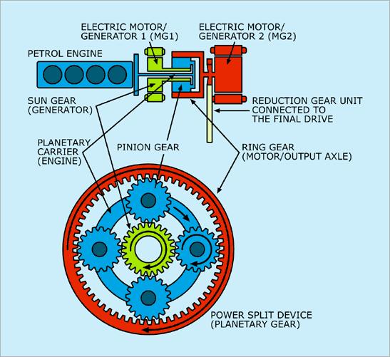
47 48
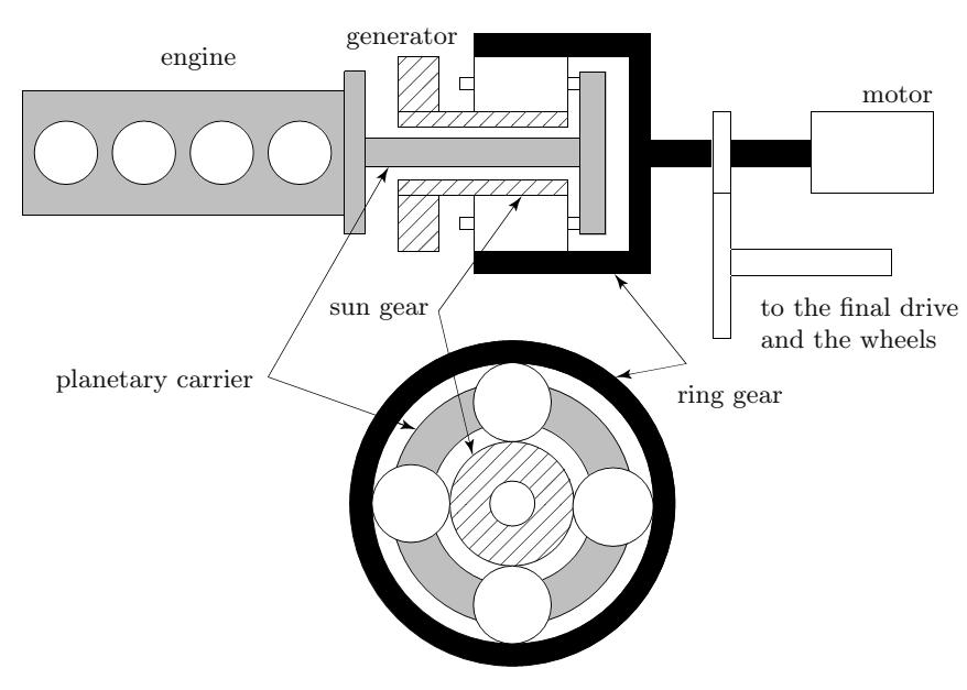
48 49
49 Idle / Standstill Engine turning carrier Generator = Zero Torque Ring «blocked» by heavy vehicle 50
50 Pure Electric / Engine off Engine off, planets blocked Generator Zero Torque Ring speed = Vehicle speed 51
51 Pure Engine Mode Planets speed = Engine speed Sun gear blocked Ring speed = Vehicle speed 52
52 CVT Mode: ω engine ω vehicle = 1 Planets speed = Engine speed Generator speed = Engine Speed Ring speed = Vehicle speed = Engine speed 53
53 CVT Mode: ω engine ω vehicle < 1 Planets speed = Engine speed Generator speed < Engine Speed Ring speed = Vehicle speed = 54
54 CVT Mode: ω engine ω vehicle > 1 Planets speed = Engine speed Generator speed > Engine Speed Ring speed = Vehicle speed = 55
55 Lever Analogy a. Pure electric ω e = 0 b. Engine on while ω f = 0 c. ω g = 0 while driving d. High ω e for acceleration 56
56 Planetary Gear Set Willis formula ω r ω c ω s ω c = z, where z = n s n r 57
57 Quick Check Assuming ω e = ω c, ω g = ω s, ω f = ω m = ω r express the engine speed as a function of the final drive speed (determined by driver) and generator speed (control input). ω f ω e ω g ω e = z, where z = n s n r ω e = ω f + zω g 1 + z 58
58 Power Split Device The transmission ratio from engine to the final drive shaft can be controlled by the generator speed. What does it cost us? ω e = ω f + zω g 1 + z 59
59 Power Split Device Applying torque and power balances yields the following: To maintain its speed, the generator needs to deliver a torque proportional to T e T g = z 1 + z T e The torque at the final crankshaft is T f = T m z T e 60
60 Power Split Device By controlling generator speed, we can control the transmission ratio between final drive and engine However, when T g = 0, then T f = T m! 61
61 Quick Check Derive the expressions for generator and engine torque. P f = P m + P e P g T f ω f = T m ω m + T e ω e T g ω g ω f + zω g T f ω f = T m ω f + T e T 1 + z g ω g ω f T f T m T e 1 + z + T g T ez 1 + z ω g = 0 ω g, ω f = 0 = 0 T e = 1 + z z T g T m = T f 1 z T g 62
62 Quick Check With your Prius you drive 50km/h and you want your engine to run at the fuel optimal operating point (i.e. 2300rpm, 100Nm). Calculate the torque and speed of both electric machines. (z=0.385 and final drive ratio = 4.6, r = 0.3). Evaluate the power balance to check for correctness. F t = 1 2 ρc da f v 2 + mgc r = = = 270N, T f = F tr γ = = 17.61Nm ω f = vγ = rad = r s 1 ω g = w e 1 + z w f 2130rpm z T g = T e = 100 = 27.80Nm 1+z z = π/ T m = T f T g = = 54.60Nm z T m ω m = = 11.63kW (charging the battery) T f ω f = = 3.75kW T e ω e = π/60 = 24.09kW T g ω g = = 8.48kW (charging the battery) Sum = = 0.23 kw (ca zero!) = rad s 63
63 Today 1. Supercaps 2. Electric Power Links 3. Torque Couplers 4. Power Split Devices 5. Continuously Variable Transmissions 64

64 Continuously Variable Transmission 65

65 Continuously Variable Transmission 66

66 Example: Variomatik 67
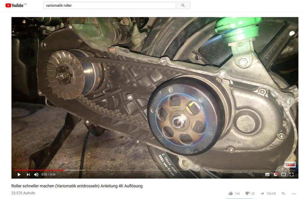
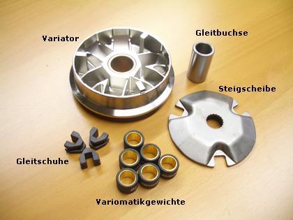
67 Variomatik 68


68 Variator w eng F c = kω eng F c F s = cδx 69
69 Variomatik ω eng Weights fully outside ω eng v veh = γ min r wh Stabilization Speed = f(weight) Weights moving towards outside ω eng v veh = γ max r wh Weights fully retracted v veh 70

70 Maximum Power vs Speed 71

71 Test with 3 different Vario-Weights 72
72 CVT Transmission ratio γ = ω 1 ω 2 Transmitted torque T 1 = 1 γ T 2 73
73 ሶ More detailed model More detailed model including losses, inertia, actuator dynamics T 1 = 1 γ T 2 + T loss + Θ 1γ 2 + Θ 2 γ γ = u CVT ωሶ 2 + γω ሶ 2 Often, losses or static efficiency is tabulated as a function of torque and speed 74
74 Engine and Clutch In a graph in the vehicle speed vs traction force plane, explain how the fastest possible acceleration to top-speed can be achieved. F t T e,max γ 1 r wh T e,max γ 2 r wh T e,max γ 3 r wh F t v = P e,max 4 5 Vehicle Engine 1. Standstill 2. Speed up engine 3. Apply clutch 4. Synchronize 5. Shift 6. 3 T e,max γ 4 r wh 1 2 T e,max γ 5 r wh v = 0 ω idle r wh γ 1 ω max r wh γ 1 v 75
Vehicle Propulsion Systems. Lecture 8 Electric & Hybrid Electric Propulsion Systems Part II
 Vehicle Propulsion Systems Lecture 8 Electric & Hybrid Electric Propulsion Systems Part II 1 Planning of Lectures and Exercises: Week Lecture, Friday, 8:15-10:00, ML F34 Book chp. 38, 21.09.2018 Introduction,
Vehicle Propulsion Systems. Tutorial Lecture on 22 nd of Dec.
 Vehicle Propulsion Systems Tutorial Lecture on 22 nd of Dec. Planning of Lectures and Exercises: Week Lecture, Friday, 8:15-10:00, ML F34 Book chp. 38, 22.9.2017 Introduction, goals, overview propulsion
Methods and Tools. Average Operating Point Approach. To lump all engine operating points into one single average operating point.
 Methods and Tools Average Operating Point Approach To lump all engine operating points into one single average operating point. Used to estimate the fuel consumption Test cycle needs to be specified when
Electric Vehicle Performance Power and Efficiency
 Electric Vehicle Performance Power and Efficiency 1 Assignment a) Examine measurement guide and electric vehicle (EV) arrangement. b) Drive the route according to teacher s instruction and download measured
Real-time energy management of the Volvo V60 PHEV based on a closed-form minimization of the Hamiltonian
 Real-time energy management of the Volvo V6 PHEV based on a closed-form minimization of the Hamiltonian Viktor Larsson 1, Lars Johannesson 1, Bo Egardt 1 Andreas Karlsson 2, Anders Lasson 2 1 Department
Lecture 3: Electrical Power and Energy
 Lecture 3: Electrical Power and Energy Recall from Lecture 2 E (V) I R E Voltage Similar to water pressure Unit: Volts (V) I Current Similar to water flow Unit: Amperes (A) R Resistance Similar to water
Parameter Prediction and Modelling Methods for Traction Motor of Hybrid Electric Vehicle
 Page 359 World Electric Vehicle Journal Vol. 3 - ISSN 232-6653 - 29 AVERE Parameter Prediction and Modelling Methods for Traction Motor of Hybrid Electric Vehicle Tao Sun, Soon-O Kwon, Geun-Ho Lee, Jung-Pyo
A capacitor is a device that stores electric charge (memory devices). A capacitor is a device that stores energy E = Q2 2C = CV 2
. A capacitor is a device that stores energy E = Q2 2C = CV 2") Capacitance: Lecture 2: Resistors and Capacitors Capacitance (C) is defined as the ratio of charge (Q) to voltage (V) on an object: C = Q/V = Coulombs/Volt = Farad Capacitance of an object depends on geometry
Capacitance: Lecture 2: Resistors and Capacitors Capacitance (C) is defined as the ratio of charge (Q) to voltage (V) on an object: C = Q/V = Coulombs/Volt = Farad Capacitance of an object depends on geometry
HEV Optimization. Ganesh Balasubramanian Grad. Berrin Daran Grad. Sambasivan Subramanian Grad. Cetin Yilmaz Grad.
 HEV Optimization By Ganesh Balasubramanian Grad. Berrin Daran Grad. Sambasivan Subramanian Grad. Cetin Yilmaz Grad. ME 555 01-5 Winter 2001 Final Report Abstract The design project is the optimization
Transmission and Gear Shift calculation in VECTO
 Working Paper No. HDH-13-04e (13th HDH meeting, 21/22 March 2013) Transmission and Gear Shift calculation in VECTO (European Tool for HDV CO2 testing) Stefan Hausberger, Martin Rexeis, Raphael Luz Borlaenge,
Charge/discharge control of a train with on-board energy storage devices for energy minimization and consideration of catenary free operation
 Energy Management in the Train Operation 65 Charge/discharge control of a train with on-board energy storage devices for energy minimization and consideration of catenary free operation M. Miyatake, K.
DC Circuits. Circuits and Capacitance Worksheet. 10 Ω resistance. second? on the sodium is the same as on an electron, but positive.
 Circuits and Capacitance Worksheet DC Circuits 1. A current of 1.30 A flows in a wire. How many electrons are flowing past any point in the wire per second? 2. What is the current in amperes if 1200 Na
Modeling and Simulation Revision IV D R. T A R E K A. T U T U N J I P H I L A D E L P H I A U N I V E R S I T Y, J O R D A N
 Modeling and Simulation Revision IV D R. T A R E K A. T U T U N J I P H I L A D E L P H I A U N I V E R S I T Y, J O R D A N 2 0 1 7 Modeling Modeling is the process of representing the behavior of a real
PhysicsAndMathsTutor.com 1
 PhysicsAndMathsTutor.com 1 Q1. A 400 μf capacitor is charged so that the voltage across its plates rises at a constant rate from 0 V to 4.0 V in 20 s. What current is being used to charge the capacitor?
Modeling and Simulation Revision III D R. T A R E K A. T U T U N J I P H I L A D E L P H I A U N I V E R S I T Y, J O R D A N
 Modeling and Simulation Revision III D R. T A R E K A. T U T U N J I P H I L A D E L P H I A U N I V E R S I T Y, J O R D A N 0 1 4 Block Diagrams Block diagram models consist of two fundamental objects:
Lecture 4: Losses and Heat Transfer
 1 / 26 Lecture 4: Losses and Heat Transfer ELEC-E845 Electric Drives (5 ECTS) Marko Hinkkanen Aalto University School of Electrical Engineering Autumn 215 2 / 26 Learning Outcomes After this lecture and
POG Modeling of Automotive Systems
 POG Modeling of Automotive Systems MORE on Automotive - 28 Maggio 2018 Prof. Roberto Zanasi Graphical Modeling Techniques Graphical Techniques for representing the dynamics of physical systems: 1) Bond-Graph
COPYRIGHTED MATERIAL. DC Review and Pre-Test. Current Flow CHAPTER
 Kybett c0.tex V3-03/3/2008 8:44pm Page CHAPTER DC Review and Pre-Test Electronics cannot be studied without first understanding the basics of electricity. This chapter is a review and pre-test on those
Chapter 18 Electric Currents
 Chapter 18 Electric Currents 1 The Electric Battery Volta discovered that electricity could be created if dissimilar metals were connected by a conductive solution called an electrolyte. This is a simple
METHOD FOR ANALYZING EPICYCLIC GEARBOXES
 International Journal of Automotive Technology Vol. No. pp. 67 7 () DOI.7/s39 4 Copyright KSAE 9 938//5 4 METHOD FOR ANALYZING EPICYCLIC GEARBOXES T. CIOBOTARU )* D. FRUNZETI ) and L. JÄNTSCHI ) ) Military
Lecture (20) DC Machine Examples Start of Synchronous Machines
 DC Machine Examples Start of Synchronous Machines") Lecture (20) DC Machine Examples Start of Synchronous Machines Energy Systems Research Laboratory, FIU All rights reserved. 20-1 Energy Systems Research Laboratory, FIU All rights reserved. 20-2 Ra R f
Lecture (20) DC Machine Examples Start of Synchronous Machines Energy Systems Research Laboratory, FIU All rights reserved. 20-1 Energy Systems Research Laboratory, FIU All rights reserved. 20-2 Ra R f
PHY102 Electricity Course Summary
 TOPIC 1 ELECTOSTTICS PHY1 Electricity Course Summary Coulomb s Law The magnitude of the force between two point charges is directly proportional to the product of the charges and inversely proportional
Physics 115. General Physics II. Session 24 Circuits Series and parallel R Meters Kirchoff s Rules
 Physics 115 General Physics II Session 24 Circuits Series and parallel R Meters Kirchoff s Rules R. J. Wilkes Email: phy115a@u.washington.edu Home page: http://courses.washington.edu/phy115a/ 5/15/14 Phys
Chapter 28. Direct Current Circuits
 Chapter 28 Direct Current Circuits Circuit Analysis Simple electric circuits may contain batteries, resistors, and capacitors in various combinations. For some circuits, analysis may consist of combining
Coulomb s constant k = 9x10 9 N m 2 /C 2
 1 Part 2: Electric Potential 2.1: Potential (Voltage) & Potential Energy q 2 Potential Energy of Point Charges Symbol U mks units [Joules = J] q 1 r Two point charges share an electric potential energy
(3.5.1) V E x, E, (3.5.2)
 V E x, E, (3.5.2)") Lecture 3.5 Capacitors Today we shall continue our discussion of electrostatics and, in particular, the concept of electrostatic potential energy and electric potential. The main example which we have
Lecture 3.5 Capacitors Today we shall continue our discussion of electrostatics and, in particular, the concept of electrostatic potential energy and electric potential. The main example which we have
Version 001 CIRCUITS holland (1290) 1
 1") Version CIRCUITS holland (9) This print-out should have questions Multiple-choice questions may continue on the next column or page find all choices before answering AP M 99 MC points The power dissipated
Version CIRCUITS holland (9) This print-out should have questions Multiple-choice questions may continue on the next column or page find all choices before answering AP M 99 MC points The power dissipated
Chapter 28 Solutions
 Chapter 8 Solutions 8.1 (a) P ( V) R becomes 0.0 W (11.6 V) R so R 6.73 Ω (b) V IR so 11.6 V I (6.73 Ω) and I 1.7 A ε IR + Ir so 15.0 V 11.6 V + (1.7 A)r r 1.97 Ω Figure for Goal Solution Goal Solution
Physics 1502: Lecture 8 Today s Agenda. Today s Topic :
 Physics 1502: Lecture 8 Today s Agenda Announcements: Lectures posted on: www.phys.uconn.edu/~rcote/ HW assignments, solutions etc. Homework #3: On Masterphysics today: due next Friday Go to masteringphysics.com
Physical Modelling with Simscape Rick Hyde
 Physical Modelling with Simscape Rick Hyde 1 2013 The MathWorks, Inc. Outline Part 1: Introduction to Simscape Review approaches to modelling Overview of Simscape-based libraries Introduction to physical
Electric Currents. Resistors (Chapters 27-28)
") Electric Currents. Resistors (Chapters 27-28) Electric current I Resistance R and resistors Relation between current and resistance: Ohm s Law Resistivity ρ Energy dissipated by current. Electric power
Electric Currents. Resistors (Chapters 27-28) Electric current I Resistance R and resistors Relation between current and resistance: Ohm s Law Resistivity ρ Energy dissipated by current. Electric power
OUTCOME 3 - TUTORIAL 2
 Unit : Unit code: QCF evel: 4 Credit value: 15 SYABUS Engineering Science /601/1404 OUTCOME 3 - TUTORIA Be able to apply DC theory to solve electrical and electronic engineering problems DC electrical
Exercise 8 - Turbocompressors
 Exercise 8 - Turbocompressors A turbocompressor TC) or turbocharger is a mechanical device used in internal combustion engines to enhance their power output. The basic idea of a TC is to force additional
Model of a DC Generator Driving a DC Motor (which propels a car)
") Model of a DC Generator Driving a DC Motor (which propels a car) John Hung 5 July 2011 The dc is connected to the dc as illustrated in Fig. 1. Both machines are of permanent magnet type, so their respective
Model of a DC Generator Driving a DC Motor (which propels a car) John Hung 5 July 2011 The dc is connected to the dc as illustrated in Fig. 1. Both machines are of permanent magnet type, so their respective
Energy Management Strategies for Vehicle Power Nets
 Energy Management Strategies for Vehicle Power Nets Michiel Koot, Bram de Jager Department of Mechanical Engineering Technische Universiteit Eindhoven P.O. Box 513, 56 MB Eindhoven The Netherlands M.W.T.Koot@tue.nl
Outline. Vehicle Propulsion Systems Lecture 6. Hybrid Electrical Vehicles Serial. Hybrid Electrical Vehicles Parallel
 Vehicle Propulsion Systems Lecture 6 Non Electric Hybri Propulsion Systems Lars Eriksson Associate Professor (Docent) Vehicular Systems Linköping University November 8, Pneumatic Hybri Engine Systems Case
Input Capacitor and Over Voltage Protection Circuit Design. Application Note
 AN13 Input Capacitor and Over-Voltage Protection Circuit Design Input Capacitor and Over Voltage Protection Circuit Design Application Note Prepared by Leo Zhang and Hongqiang Qin February 018 AN13 Rev.
Solved Problems. Electric Circuits & Components. 1-1 Write the KVL equation for the circuit shown.
 Solved Problems Electric Circuits & Components 1-1 Write the KVL equation for the circuit shown. 1-2 Write the KCL equation for the principal node shown. 1-2A In the DC circuit given in Fig. 1, find (i)
General Physics (PHY 2140)
") General Physics (PHY 2140) Lecture 7 Electrostatics and electrodynamics Capacitance and capacitors capacitors with dielectrics Electric current current and drift speed resistance and Ohm s law http://www.physics.wayne.edu/~apetrov/phy2140/
General Physics (PHY 2140) Lecture 7 Electrostatics and electrodynamics Capacitance and capacitors capacitors with dielectrics Electric current current and drift speed resistance and Ohm s law http://www.physics.wayne.edu/~apetrov/phy2140/
MAE106 Homework 2 - Solution DC Motors & Intro to the frequency domain
 MAE06 Homework 2 - Solution DC Motors & Intro to the frequency domain University of California, Irvine Department of Mechanical and Aerospace Engineering Problem You are given the circuit shown in Figure.
AC vs. DC Circuits. Constant voltage circuits. The voltage from an outlet is alternating voltage
 Circuits AC vs. DC Circuits Constant voltage circuits Typically referred to as direct current or DC Computers, logic circuits, and battery operated devices are examples of DC circuits The voltage from
Power System Analysis Prof. A. K. Sinha Department of Electrical Engineering Indian Institute of Technology, Kharagpur
 Power System Analysis Prof. A. K. Sinha Department of Electrical Engineering Indian Institute of Technology, Kharagpur Lecture - 9 Transmission Line Steady State Operation Welcome to lesson 9, in Power
Physics Investigation 10 Teacher Manual
 Physics Investigation 10 Teacher Manual Observation When a light bulb is connected to a number of charged capacitors, it lights up for different periods of time. Problem What does the rate of discharging
(Refer Slide Time: 00:01:30 min)
") Control Engineering Prof. M. Gopal Department of Electrical Engineering Indian Institute of Technology, Delhi Lecture - 3 Introduction to Control Problem (Contd.) Well friends, I have been giving you various
Control Engineering Prof. M. Gopal Department of Electrical Engineering Indian Institute of Technology, Delhi Lecture - 3 Introduction to Control Problem (Contd.) Well friends, I have been giving you various
Louisiana State University Physics 2102, Exam 2, March 5th, 2009.
 PRINT Your Name: Instructor: Louisiana State University Physics 2102, Exam 2, March 5th, 2009. Please be sure to PRINT your name and class instructor above. The test consists of 4 questions (multiple choice),
Experiment FT1: Measurement of Dielectric Constant
 Experiment FT1: Measurement of Dielectric Constant Name: ID: 1. Objective: (i) To measure the dielectric constant of paper and plastic film. (ii) To examine the energy storage capacity of a practical capacitor.
LECTURE 8. Hydraulic machines and systems II 2002 MIT PSDAM LAB
 LECTURE 8 Hydraulic machines and systems II Basic hydraulic machines & components Graphical Nomenclature Arrows show direction of flow Control Volume Pipe or hose with fluid flow Pipe or hose without fluid
Transduction Based on Changes in the Energy Stored in an Electrical Field
 Lecture 6- Transduction Based on Changes in the Energy Stored in an Electrical Field Actuator Examples Microgrippers Normal force driving In-plane force driving» Comb-drive device F = εav d 1 ε oε F rwv
LESSON 20 ALTERNATOR OPERATION OF SYNCHRONOUS MACHINES
 ET 332b Ac Motors, Generators and Power Systems LESSON 20 ALTERNATOR OPERATION OF SYNCHRONOUS MACHINES 1 LEARNING OBJECTIVES After this presentation you will be able to: Interpret alternator phasor diagrams
Power System and Controller Design for Hybrid Fuel Cell Vehicles
 Power System and Controller Design for Hybrid Fuel Cell Vehicles Syed K. Ahmed Donald J. Chmielewski Department of Chemical and Biological Engineering Illinois Institute of Technology Presented at the
Electromagnetic Oscillations and Alternating Current. 1. Electromagnetic oscillations and LC circuit 2. Alternating Current 3.
 Electromagnetic Oscillations and Alternating Current 1. Electromagnetic oscillations and LC circuit 2. Alternating Current 3. RLC circuit in AC 1 RL and RC circuits RL RC Charging Discharging I = emf R
DEPARTMENT OF COMPUTER ENGINEERING UNIVERSITY OF LAHORE
 DEPARTMENT OF COMPUTER ENGINEERING UNIVERSITY OF LAHORE NAME. Section 1 2 3 UNIVERSITY OF LAHORE Department of Computer engineering Linear Circuit Analysis Laboratory Manual 2 Compiled by Engr. Ahmad Bilal
CIRCUIT ELEMENT: CAPACITOR
 CIRCUIT ELEMENT: CAPACITOR PROF. SIRIPONG POTISUK ELEC 308 Types of Circuit Elements Two broad types of circuit elements Ati Active elements -capable of generating electric energy from nonelectric energy
Powertrain Systems of the Future
 25 Powertrain Systems of the Future Engine, transmission and damper systems for downspeeding, downsizing, and cylinder deactivation F T O I E O H O I O O A N G A D F J G I O J E R U I N K O P O A N G A
Introduction to AC Circuits (Capacitors and Inductors)
") Introduction to AC Circuits (Capacitors and Inductors) Amin Electronics and Electrical Communications Engineering Department (EECE) Cairo University elc.n102.eng@gmail.com http://scholar.cu.edu.eg/refky/
Introduction to AC Circuits (Capacitors and Inductors) Amin Electronics and Electrical Communications Engineering Department (EECE) Cairo University elc.n102.eng@gmail.com http://scholar.cu.edu.eg/refky/
3/17/2009 PHYS202 SPRING Lecture notes Electric Circuits
 PHYS202 SPRING 2009 Lecture notes Electric Circuits 1 Batteries A battery is a device that provides a potential difference to two terminals. Different metals in an electrolyte will create a potential difference,
University of Jordan Faculty of Engineering & Technology Electric Power Engineering Department
 University of Jordan Faculty of Engineering & Technology Electric Power Engineering Department EE471: Electrical Machines-II Tutorial # 2: 3-ph Induction Motor/Generator Question #1 A 100 hp, 60-Hz, three-phase
Physics 115. AC: RL vs RC circuits Phase relationships RLC circuits. General Physics II. Session 33
 Session 33 Physics 115 General Physics II AC: RL vs RC circuits Phase relationships RLC circuits R. J. Wilkes Email: phy115a@u.washington.edu Home page: http://courses.washington.edu/phy115a/ 6/2/14 1
Letter STUDENT NUMBER SYSTEMS ENGINEERING. Written examination. Monday 14 November 2016
 Victorian Certificate of Education 2016 SUPERVISOR TO ATTACH PROCESSING LABEL HERE Letter STUDENT NUMBER SYSTEMS ENGINEERING Written examination Monday 14 November 2016 Reading time: 9.00 am to 9.15 am
ENGR 1100 Introduction to Mechanical Engineering
 ENGR 1100 Introduction to Mechanical Engineering Mech. Engineering Objectives Newton s Laws of Motion Free Body Diagram Transmissibility Forces and Moments as vectors Parallel Vectors (addition/subtraction)
2.000 Homework # 4: Machine components
 Name: Weight: 100 pts Due: Day 10 at beginning of lecture (date differs from original syllabus) You must return your screwdriver in working condition! 1. Screw driver stall torque a). [10] Perform an experiment
Physics 1202: Lecture 4 Today s Agenda. Today s Topic :
 Physics 1202: Lecture 4 Today s Agenda Announcements: Lectures posted on: www.phys.uconn.edu/~rcote/ HW assignments, solutions etc. Homework #1: On Masterphysics: due this coming Friday Go to the syllabus
B THE CAPACITOR. Theory
 8. THE CAPACITOR You will study several aspects of a capacitor, how the voltage across it changes with time as it is being charged and discharged and how it stores energy. The most well known device for
Problem Solutions. Vehicle Energy and Fuel Consumption. Vehicle Energy Losses and Performance Analysis. Problem 2.1
 Problem Solutions Vehicle Energy and Fuel Consumption Vehicle Energy Losses and Performance Analysis Problem 2.1 For a vehicle with m v = 1500 kg, A f c d = 0.7m 2, c r = 0.012, a vehicle speed v = 120km/h
Electricity
 Electricity Electric Charge There are two fundamental charges in the universe. Positive (proton) has a charge of +1.60 x 10⁻¹⁹ C Negative (electron) has a charge of 1.60 x 10⁻¹⁹ C There is one general
Prof. Anyes Taffard. Physics 120/220. Voltage Divider Capacitor RC circuits
 Prof. Anyes Taffard Physics 120/220 Voltage Divider Capacitor RC circuits Voltage Divider The figure is called a voltage divider. It s one of the most useful and important circuit elements we will encounter.
Physics 102: Lecture 7 RC Circuits
 Physics 102: Lecture 7 C Circuits Physics 102: Lecture 7, Slide 1 C Circuits Circuits that have both resistors and capacitors: K Na Cl C ε K ε Na ε Cl S With resistance in the circuits, capacitors do not
AP Physics C - E & M
 AP Physics C - E & M Current and Circuits 2017-07-12 www.njctl.org Electric Current Resistance and Resistivity Electromotive Force (EMF) Energy and Power Resistors in Series and in Parallel Kirchoff's
KINGS COLLEGE OF ENGINEERING Punalkulam
 KINGS COLLEGE OF ENGINEERING Punalkulam 613 303 DEPARTMENT OF ELECTRICAL AND ELECTRONICS ENGINEERING POWER SYSTEM ANALYSIS QUESTION BANK UNIT I THE POWER SYSTEM AN OVERVIEW AND MODELLING PART A (TWO MARK
Capacitance, Resistance, DC Circuits
 This test covers capacitance, electrical current, resistance, emf, electrical power, Ohm s Law, Kirchhoff s Rules, and RC Circuits, with some problems requiring a knowledge of basic calculus. Part I. Multiple
About the hand-in tasks. Vehicle Propulsion Systems Lecture 3. Outline. Energy System Overview. W2M Energy Paths. The Vehicle Motion Equation
 About the han-in tasks Vehicle Propulsion Systems Lecture 3 Conventional Powertrains with Transmission Performance, Tools an Optimization Lars Eriksson Professor Vehicular Systems Linköping University
A 954 C HD. Technical Description Hydraulic Excavator. Machine for Industrial Applications
 Technical Description Hydraulic Excavator A 95 C HD litronic` Machine for Industrial Applications Operating Weight 165,800 170,0 lb Engine Output 36 hp (0 kw) Technical Data Engine Rating per ISO 99 0
Physics 202, Lecture 8. Exam 1
 Physics 202, Lecture 8 Today s Topics More on Exam 1: logistics and mini-review Current And Resistance (Ch. 27) Current: Macroscopic and Microscopic Resistance: Macroscopic and Microscopic Electrical Power
DC motors. 1. Parallel (shunt) excited DC motor
 excited DC motor") DC motors 1. Parallel (shunt) excited DC motor A shunt excited DC motor s terminal voltage is 500 V. The armature resistance is 0,5 Ω, field resistance is 250 Ω. On a certain load it takes 20 A current
DC motors 1. Parallel (shunt) excited DC motor A shunt excited DC motor s terminal voltage is 500 V. The armature resistance is 0,5 Ω, field resistance is 250 Ω. On a certain load it takes 20 A current
ECEN 420 LINEAR CONTROL SYSTEMS. Lecture 6 Mathematical Representation of Physical Systems II 1/67
 1/67 ECEN 420 LINEAR CONTROL SYSTEMS Lecture 6 Mathematical Representation of Physical Systems II State Variable Models for Dynamic Systems u 1 u 2 u ṙ. Internal Variables x 1, x 2 x n y 1 y 2. y m Figure
EDEXCEL NATIONALS UNIT 5 - ELECTRICAL AND ELECTRONIC PRINCIPLES. ASSIGNMENT No. 3 - ELECTRO MAGNETIC INDUCTION
 EDEXCEL NATIONALS UNIT 5 - ELECTRICAL AND ELECTRONIC PRINCIPLES ASSIGNMENT No. 3 - ELECTRO MAGNETIC INDUCTION NAME: I agree to the assessment as contained in this assignment. I confirm that the work submitted
Review. Spring Semester /21/14. Physics for Scientists & Engineers 2 1
 Review Spring Semester 2014 Physics for Scientists & Engineers 2 1 Notes! Homework set 13 extended to Tuesday, 4/22! Remember to fill out SIRS form: https://sirsonline.msu.edu Physics for Scientists &
ENGR 2405 Chapter 6. Capacitors And Inductors
 ENGR 2405 Chapter 6 Capacitors And Inductors Overview This chapter will introduce two new linear circuit elements: The capacitor The inductor Unlike resistors, these elements do not dissipate energy They
Transduction Based on Changes in the Energy Stored in an Electrical Field
 Lecture 6-1 Transduction Based on Changes in the Energy Stored in an Electrical Field Electric Field and Forces Suppose a charged fixed q 1 in a space, an exploring charge q is moving toward the fixed
Current and Resistance
 Current and Resistance 1 Define the current. Understand the microscopic description of current. Discuss the rat at which the power transfer to a device in an electric current. 2 2-1 Electric current 2-2
Review: control, feedback, etc. Today s topic: state-space models of systems; linearization
 Plan of the Lecture Review: control, feedback, etc Today s topic: state-space models of systems; linearization Goal: a general framework that encompasses all examples of interest Once we have mastered
Chapters 24/25: Current, Circuits & Ohm s law Thursday September 29 th **Register your iclickers**
 Chapters 24/25: Current, Circuits & Ohm s law Thursday September 29 th **Register your iclickers** Conductors under dynamic conditions Current, current density, drift velocity Ohm s law Types of conductor
Training III. Force Generation and Transmission. Team 2228 CougarTech 1
 Training III Force Generation and Transmission Team 2228 CougarTech 1 Team 2228 CougarTech 2 Force Generation and Transmission Objectives Understand Energy Conversion to do Work on Robots Understand mechanical
Chapter 7: Stepper Motors. (Revision 6.0, 27/10/2014)
") Chapter 7 Stepper Motors (Revision 6.0, 7/10/014) 1. Stepping Angle Analysis The following analysis derives the formula for the stepping angle of the stepper motor. It has been reproduced and edited from
Chapter 7 Stepper Motors (Revision 6.0, 7/10/014) 1. Stepping Angle Analysis The following analysis derives the formula for the stepping angle of the stepper motor. It has been reproduced and edited from
Physics 142 Steady Currents Page 1. Steady Currents
 Physics 142 Steady Currents Page 1 Steady Currents If at first you don t succeed, try, try again. Then quit. No sense being a damn fool about it. W.C. Fields Electric current: the slow average drift of
Circuit Theorems Overview Linearity Superposition Source Transformation Thévenin and Norton Equivalents Maximum Power Transfer
 Circuit Theorems Overview Linearity Superposition Source Transformation Thévenin and Norton Equivalents Maximum Power Transfer J. McNames Portland State University ECE 221 Circuit Theorems Ver. 1.36 1
Technical University of Graz, April 2012
 Technical University of Graz, April 2012 «Energy Management of EVs & HEVs using Energetic Macroscopic Representation» Dr. Philippe Barrade*, Dr. Walter LHOMME**, Prof. Alain BOUSCAYROL** * LEI, Ecole Polytechnique
ELECTRICAL FUNDAMENTALS
 Part 66 Cat. B1 / B2 Module 3 ELECTRICAL FUNDAMENTALS Vilnius-2017 Issue 1. Effective date 2017-02-28 FOR TRAINING PURPOSES ONLY Page 1 of 280 If we look at electronic configuration of a carbon C atom,
ENERGY AND TIME CONSTANTS IN RC CIRCUITS By: Iwana Loveu Student No Lab Section: 0003 Date: February 8, 2004
 ENERGY AND TIME CONSTANTS IN RC CIRCUITS By: Iwana Loveu Student No. 416 614 5543 Lab Section: 0003 Date: February 8, 2004 Abstract: Two charged conductors consisting of equal and opposite charges forms
(d) describe the action of a 555 monostable timer and then use the equation T = 1.1 RC, where T is the pulse duration
 describe the action of a 555 monostable timer and then use the equation T = 1.1 RC, where T is the pulse duration") Chapter 1 - Timing Circuits GCSE Electronics Component 2: Application of Electronics Timing Circuits Learners should be able to: (a) describe how a RC network can produce a time delay (b) describe how
Chapter 1 - Timing Circuits GCSE Electronics Component 2: Application of Electronics Timing Circuits Learners should be able to: (a) describe how a RC network can produce a time delay (b) describe how
DC Circuits. Electromotive Force Resistor Circuits. Kirchoff s Rules. RC Circuits. Connections in parallel and series. Complex circuits made easy
 DC Circuits Electromotive Force esistor Circuits Connections in parallel and series Kirchoff s ules Complex circuits made easy C Circuits Charging and discharging Electromotive Force (EMF) EMF, E, is the
University Physics (PHY 2326)
") Chapter 25 University Physics (PHY 2326) Lecture 7 Electrostatics and electrodynamics Capacitance and capacitors capacitors with dielectrics Electric current current and drift speed resistance and Ohm
Chapter 25 University Physics (PHY 2326) Lecture 7 Electrostatics and electrodynamics Capacitance and capacitors capacitors with dielectrics Electric current current and drift speed resistance and Ohm
Basics of Network Theory (Part-I)
") Basics of Network Theory (Part-I) 1. One coulomb charge is equal to the charge on (a) 6.24 x 10 18 electrons (b) 6.24 x 10 24 electrons (c) 6.24 x 10 18 atoms (d) none of the above 2. The correct relation
Basics of Network Theory (Part-I) 1. One coulomb charge is equal to the charge on (a) 6.24 x 10 18 electrons (b) 6.24 x 10 24 electrons (c) 6.24 x 10 18 atoms (d) none of the above 2. The correct relation
Designing Information Devices and Systems I Fall 2015 Anant Sahai, Ali Niknejad Homework 8. This homework is due October 26, 2015, at Noon.
 EECS 16A Designing Information Devices and Systems I Fall 2015 Anant Sahai, Ali Niknejad Homework 8 This homework is due October 26, 2015, at Noon. 1. Nodal Analysis Or Superposition? (a) Solve for the
3. Cautions for use 3-1. Voltage 3-2. Self heating 3-3. Mounting conditions 3-4. Storage conditions
 Technical Guide of Electrical Double Layer Capacitor 1. The Structure and Principles of Electrical Double Layer Capacitor 1-1. Principles of Electrical Double Layer Capacitor (EDLC) 1-2. Structure of EDLC
EE155/255 Green Electronics
 EE155/255 Green Electronics Electric Motors 10/19/16 Prof. William Dally Computer Systems Laboratory Stanford University This week is flipped Course Logistics Discussion on 10/17, Motors on 10/19, Isolated
Chapter 26. Capacitance and Dielectrics
 Chapter 26 Capacitance and Dielectrics Capacitors Capacitors are devices that store electric charge Examples of where capacitors are used include: radio receivers filters in power supplies to eliminate
Design Engineering MEng EXAMINATIONS 2016
 IMPERIAL COLLEGE LONDON Design Engineering MEng EXAMINATIONS 2016 For Internal Students of the Imperial College of Science, Technology and Medicine This paper is also taken for the relevant examination
Physics 1302W.400 Lecture 33 Introductory Physics for Scientists and Engineering II
 Physics 1302W.400 Lecture 33 Introductory Physics for Scientists and Engineering II In today s lecture, we will discuss generators and motors. Slide 30-1 Announcement Quiz 4 will be next week. The Final
Supplementary Figure 1. Theoretical calculation results to optimize the FEP layer thickness
 Supplementary Figures: Supplementary Figure 1. Theoretical calculation results to optimize the FEP layer thickness Supplementary Figure 2. SEM picture of the surface of (a) FEP (b) Al foil Supplementary