DEPARTMENT OF TECHNOLOGY
|
|
|
- Lydia Bradford
- 5 years ago
- Views:
Transcription
1 DEPARTMENT OF TECHNOLOGY Moment Balance of an axisymmetric jet and the effect of air entrainment from ambient Xue Fei May 2010 Master s Thesis in Building Environment Modeling - CFD, Measuring Techniques and Visualization Supervisor: Mats Sandberg Examiner: Taghi Karimipanah
2
3 Preface The author wishes to thank supervisor Mats Sandberg for his patient help and crucial discussions, Claes Blomqvist for his kindly help with the instruments. The author also would like to thank Taghi Karimipanah for helping me access to this project and essential discussions. I
4 II
5 Abstract The momentum flux of turbulent impinging jet is not conserved causing a transfer of momentum between the jet and its ambient, which may result in either increasing or decreasing the momentum flux of the jet. In order to study the nature of the momentum variation, the reaction force of an axisymmetric jet was measured by issuing the jet from a round nozzle against a plate which is placed on a digital balance. Tests were carried out in an almost infinite ambient with different heights for Reynolds between and Different sizes of ceilings were installed around the nozzle to examine the influence of the air entrainment from ceiling level into the jet. Visualization was performed to understand better the effect of the entrainment. The results show, after a certain distance, the reaction force becomes larger than the momentum flux at the inlet. By using wider ceilings around the jet supply outlet, the reaction force, which is normalized by the inlet momentum, was slightly decreased. III
6 IV
7 Content 1 Introduction Sensitivity of the balance Method of Test Experimental Set-up Results Jet with a small ceiling on top of the control volume Jet with a round sheet on top of the control volume Jet with an extended sheet on top of the control volume General comparing Conclusion References Appendix...33 Ⅰ Details for L=0.12 m at air flow 16.7 l/s Ⅱ Details for L=0.12 m at air flow 18.7 l/s...37 Ⅲ Details for L=2 m at air flow 16.7 l/s...39 Ⅳ Details for L=2 m at air flow 18.7 l/s...41 Ⅴ Details for L=3 m at air flow 16.7 l/s...43 Ⅵ Details for L=3 m at air flow 18.7 l/s...45 V
8 VI
9 Nomenclature A: Area of impinging plate (A= D 2 /4) [m 2 ] A f : Free area of supply device [m 2 ] D: Impinging plate diameter [m] d: Diameter of nozzle [m] da: Area differential [m 2 ] F: Flow force (F=M+pA) [N] g: Gravity acceleration [m/s 2 ] h: Impinging height [m] L: Diameter of the Ceiling around nozzle [m] M: Kinematic momentum flux (M U u da) [N] M(0): Exit kinematic momentum flux at nozzle [N] q: Volumetric flow rate [m 3 /s] R: Reaction force [N] U: Instantaneous axial velocity [m/s] : Fluctuating part of axial velocity [m/s] V: Velocity of the air coming in the control volume [m/s] V r : Radial velocity component of flowing in [m/s] x: Coordinate in axial direction [m] θ: Entrainment angle [radian] ρ: Air density [Kg/m 3 ] VII
10 VIII
11 1. Introduction A turbulent impinging jet has different functions and is useful in many engineering applications, such as cooling of cast iron, glass tempering and ventilation. It has also been widely studied with different configurations. S.Maurel and C.Solliec [1] studied the plane turbulent jets impinging normally to a flat and smooth plate. Carlo Carcasci [2] investigated air impinging jets by visualisation methods. Karimipanah and Sandberg [3] studied the confinement effect of Jets in ventilated Rooms. Heskestad [4] performed hot wire measurements in a plane turbulent jet. However, the results of kinematic momentum flux of a jet in a still ambient are controversial. Many researchers showed decreasing in the momentum, for instance Brandbury (1965) [5], Goldschmidt (1975) [6], Gutmark (1976) [7], and Kotsovinos (1975) [8]. Others reported increasing momentum, as e.g. Hussain and Clark (1977) [9], Panchapakesan and Lumley (1993) [10]. Result of constancy momentum also reported by Hussein (1994) [11]. Kotsovinos and Angelidis (1991) [12] attributed the increasing or decreasing of the jet momentum flux to the direction of induced flow that enter the jet. Hussein (1994) [11] reported that the previous measurements of increasing or decreasing of momentum are not valid dependent to the model scale. Karimipanah and Sandberg [13] discussed the decay of momentum and velocity in an axisymmetric impinging jet. Karimipanah and Sandberg [14] also studied the momentum balance of an axisymmetric impinging jet both in infinite environment and within enclosure. In this work, the momentum balance of a turbulent axisymmetric jet is studied with special interest on the influence of entrainment of ambient air from ceiling level into the jet. The jets with 2 different air flow rates were investigated and, up to a distance equal to 46 exit diameters, its forces 1
12 were measured by a digital balance and recorded by a personal computer. 2
13 2. Sensitivity of the balance To investigate the sensitivity of the digital balance, Mettler ID1 weighting terminal, different activities were performed with different distance from the balance to study how to secure the weighting results of the balance from people s activities around it. Table.1 Sensitivity of the balance with people s activities from different distance Distance (m) Weight Range (g) (-13)~14 (-3)~1 (-2)~1 (-1)~2 0 0 Table.1 shows that to secure the weighting results, during the experiment, a protected area should be set with, at lease, 2.5 m as radius. In order to understand how long time common activities can affect the weighting results. The influence of running and walking close to the digital balance has been examined (See Figure.1). 5 times tests were performed for each behavior. Figure.1 Running and walking close to the balance. 3
14 Figure.2 and figure.3 show that after each adjustment, measurement should be carried out about 20 seconds later Weight (g) test 1 test 2 test 3 test 4 test 5-10 Measuring time (s) Figure.2. Sensitivity test for walking close to the balance Weight (g) test 1 test 2 test 3 test 4 test 5-15 Measuring time (s) Figure.3 Sensitivity test for running close to the balance 4
15 3. Method of Test An axisymmetric jet was issued from a round nozzle and perpendicularly impinges on the centre of a black circular plate. The flow force of the axisymmetric jet on the impingement plate was weighted by a balance which is mounted under the impingement plate, See figure.4. The kinematic momentum flux of a free turbulent jet is defined as M = U 2 + u 2 da (1) Where U is the instantaneous axial velocity and uu is the fluctuating part of axial velocity. If one assumes that the air pressures under the plate and at the top of the control volume are equal to the pressure in the ambient, then the reaction force is h 2 AA uuuu RR (h) = MM 0 ππππ ρρvvrr 0 tttttttt(xx)dddd + AAnnnnnnnnnnnn ρρuu 2 dddd (2) Where VV rr is the radial velocity component of the entrainment velocity. One assumes θ is the angle that the entrained air enters the control volume. (See figure.4) 5
16 Figure.4 Schematic view of the test bench without ceiling on top of the control volume With special interest of the air entrainment from the ceiling level, a round sheet was placed around the nozzle, See figure.5, and the net force becomes RR (h) = MM 0 ππππ 0 h ρρvvrr 2 tttttttt(xx)dddd (3) 6
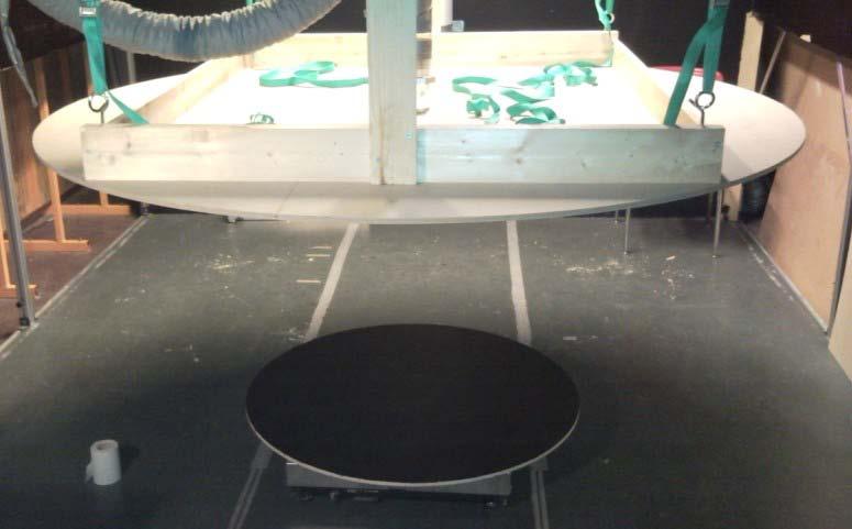
17 Figure.5 Schematic view of the test bench with ceiling on top of the control volume This ceiling was used to avoid the entrainment of ambient air from the top. Although the realistic solution which is based on the totally closed ceiling in case of ventilation applications, but the ceiling was not closed properly and this small opening caused some undesired entrainment. (See figure.6) 7
18 Figure.6 Test bench with ceiling on top of the control volume and the undesired entrainment. 8
19 4. Experimental Set-up The support for the nozzle was firmly clamped to the ground to avoid vibrations. A fan with variable power was adopted to supply different air flow rates. The device for measuring the flow rate is an orifice plate with 50 mm hole-diameter and a micro manometer, Swema 80, which was used for measuring the pressure difference between the two sides of the orifice plate. Then, with a thermometer, Digitron 2006T, and a barometer, Mechanism LTD No.M2236A, which were used for measuring local temperature and pressure respectively, air flow rate could be calculated. To calculate the air density of the jet, temperature at the nozzle was measured before sampling for each height. A digital balance, Mettler ID1 weighting terminal, with 1 gram resolution and a circular black plate with 1000 mm diameter were placed at downstream of the nozzle for measuring the weight of the jet and the results were recorded by a personal computer. For each measurement, 200 samples were taken. A well designed round nozzle with 25 mm diameter was adopted for issuing a three dimensional axisymmetric jet which was perpendicular to the centre of the impingement plate [15]. The impinging height h was arranged from about 22 to 1144 mm downstream of the nozzle. The distances between measuring points was equal to about 2 AA ff. Three different sizes of ceilings were adopted for the control volume. The diameters are 0.12 m, 2 m, 3 m respectively (See figure.7). Hysteresis appears at a few regions after installing the ceilings with L=2 m and L=3 m. To avoid it, a small board was used to horizontally blow the hysteresis air away before measures. A Philips Focus Generator PCV740 was used to make light sheet for smoke visualization. Canon D100 was used for taking long exposure photos, and the exposure time was set by 10 to 15 seconds. 9

20 (a) (b) 10

21 (c) Figure.7 Photos of Experimental Set-Up with different sizes of ceilings. (a) L=0.12 m; (b) L=2 m; (c) L=3 m. 11
22 12
23 5. Results 5.1 Jet with a small ceiling on top of the control volume Measurement was performed in an almost infinite environment. Ambient air could entrain the control volume from all the directions. (Details can be found in Appendix Ⅰ & Ⅱ) Weighting Figure.8 presents the recorded reaction force normalized by the inlet momentum flux MM (0) varying with x/d. It is noted that the normalized reaction force increases rapidly before x/d=4, then it slowly reaches its peak value after x/d=10 approximately, which is in agreement with the findings of Karimipanah and Sandberg [14]. After x/d=40, the force starts to decrease. The force increases slightly with Reynolds number and it becomes larger than the inlet momentum flux after about x/d= R/M(0) q=16.7 l/s Re=57000 L=0.12 m q=18.7 l/s Re=64300 L=0.12 m x/d Figure.8 Measured reaction force versus x/d 13
 is the smallest ceiling with 0.12 m diameter. Figure.10 shows that an inflection point of the profile of the normalized reaction force happens at about x/l=1. Figure.9 Supply terminal [16] 1.")
24 The results were also analyses in terms of the impinging distance normalized by the diameter of the ceiling of the control volume; the holder of the nozzle (see figure.9) is the smallest ceiling with 0.12 m diameter. Figure.10 shows that an inflection point of the profile of the normalized reaction force happens at about x/l=1. Figure.9 Supply terminal [16] 1.4 R/M(0) q=16.7 l/s Re=57000 L=0.12 m q=18.7 l/s Re=64300 L=0.12 m x/l Figure.10 Measured reaction force versus x/l 14

25 5.1.2 Visualization To visualize how the entrainment works, smoke visualization and long exposure camera offers an opportunity to see the view of the entrainment. Figure.11 shows the overall two dimension view. Note that the entrainment happens all the way along the jet. The angle of the entrainment increases as approaching to the plate. Two vortexes are found under the holder of the nozzle, See Figure.12, which may stop the directly air entrainment. The vortexes always appear until the distance between the plate and the ceiling is smaller than the length of the vortex. And the length of the vortex is approximately equal to the distance where the inflection point appears. Figure.11 Photo of air entrainment for Re=57000, q=16.7 l/s, x/d=30, L=0.12 m 15

26 Figure.12 Photo of air entrainment for Re=57000, q=16.7 l/s, x/d=9, L=0.12 m 5.2 Jet with a round sheet on top of the control volume A round sheet with 2 m diameter was installed to prevent ambient air entrainment from the ambient above the nozzle. (Details can be found in Appendix Ⅲ & Ⅳ) Weighting Measurements were also performed for two different air flow rates. Hysteresis appears at the region close to the inflection point for both air flow rates; the trajectory of the normalized reaction force did not follow the same path when the experiment performed from different directions (see figure 13). Below the inflection point, ambient air entrainment is stopped by the spreading wall jet (see figure.14). Figure.15 shows the normalized reaction force is quite similar between the two different Reynolds numbers. This shows that the interaction between the jet and its ambient remains almost the same. But the inflection point of the profile moves forward till 16
27 about x/d=15 to x/d=20. There is a sharply jump at the inflection point, it shows that air entrainment has strong influence on the reaction force cause air starts to entrain the control volume after the inflection point. By the inflection point, it is also able to define two regions which are deentrainment region and entrainment region respectively. Then, the profile becomes relatively stable, it slowly decreases after x/d=40. Under x/d=7, the value of the normalized reaction force is minus. It represents that the spreading wall jet has strong influence in the region between the ceiling and the impinging plate and it may strongly interact with the impinging jet. Figure.16 shows the inflection point appears at about x/l=0.2. Figure.13 Hysteresis at the inflection point, Re=57400, q=16.8 l/s, L=2m Figure.14 Ambient air entrainment stopped by the spreading wall jet 17
28 Figure.15 Measured reaction force with a round sheet on top of the control volume versus x/d Figure.16 Measured reaction force with a round sheet on top of the control volume versus x/l 18


29 5.2.2 Visualization According to the visualization, even the round sheet was installed, ambient air is still able to entrain to the control volume from the top of the round sheet. (See Figure.17 and Figure.18) Figure.17 Photo of air entrainment for Re=57400, q=16.7 l/s, x/d=46, L=2 m Figure.18 Photo of air entrainment for Re=57400, q=16.7 l/s, x/d=30, L=2 m 19
, Direct entrainment was stopped by the spreading wall jet, which is due to impingement of the jet on the impinging plate and subsequently the radial deflection of the jet trajectory.")
30 Below about x/d=15 (See figure.19), Direct entrainment was stopped by the spreading wall jet, which is due to impingement of the jet on the impinging plate and subsequently the radial deflection of the jet trajectory. Approximately, it is also the distance where the inflection point appears. Figure.19 Photo of jet spreading outward at the edge of the ceiling for Re=57400, q=16.7 l/s, x/d=14, L=2 m Spiral rotation appears at a region close to the nozzle (See figure 20); it is due to the uneven air entrainment from the different sizes of openings at different sides of the ceiling. 20

31 Figure.20 photo of spiral rotation at the region close to the nozzle for Re=57400, q=16.7 l/s, x/d=30, L=2 m 5.3 Jet with an extended sheet on top of the control volume The round sheet was extended by hard plastic. Approximately the diameter of the sheet increased to 3 meters. ( Details can be found in Appendix Ⅴ & Ⅵ ) Weighting Figure.21 shows that, with the extended sheet, the results profiles for the two air flow rates are quite similar. It is due to the same magnitude influence from the ambient air. The value of the normalized force becomes minus under x/d=7. Sharply jump appears at the inflection point. Hysteresis appears at the region close to the inflection point. Figure.22 shows the inflection point appears at about x/l=
32 Figure.21 Measured reaction force with extended sheet on top of the control volume versus x/d Figure.22 Measured reaction force with extended sheet on top of the control volume versus x/l Visualization According to the visualization(see figure.23), even with the extended 22

33 sheet of 3 meters diameter. There is still air from the top of the sheet that entrain to the control volume. Figure.23 Air entrainment at the edge of the extended sheet for Re=55300, q=16.7 l/s, x/d=30, L=3 m Figure.24 shows a rotating flow that result from the conflict between the entraining air and spreading wall jet. But when the ceiling was lowered below the distance of inflection point, a weak rotating flow with opposite direction was observed. It is due to the air entrainment from the space between ground and the impinging plate to the spreading wall jet. (See figure.25) 23


34 Figure.24 A rotating flow at the edge of the extended sheet for Re=55300, q=16.7 l/s, x/d=30, L=3 m Figure.25 A rotating flow at the edge of the extended sheet for Re=55300, q=16.7 l/s, x/d=15, L=3 m 24
35 5.4 General Comparing Figure.26 and figure.27 show the comparison for air flows rate at 16.7 l/s and 18.7 l/s with different set-up. The inflection point obviously moves forward by installing the round sheet. But the inflection point appears at almost the same place before and after extending the round sheet. It shows, after a certain length, the length of the sheet will not affect the height where ambient air stops entrain the control volume. The results profiles before and after extending the round sheet are similar. It is due to the same magnitude influence from the ambient air, and one can predict the same magnitude influence in case of ventilation application with infinite or totally closed ceiling. The sharply jump at the inflection point only appears after installing the round sheet, and the value of the normalized force is less than 1 before the jump. It shows that the outward spreading jet can stop the entrainment more effectively than the rotating flow that could result in vortexes when L=0.12 m. Note that, with the smallest ceiling, slightly higher normalized reaction force can be achieved. It also shows that the direct air entrainment from the ceiling level of the control volume does not contribute much for the increase of the jet s momentum. 25
36 l/s Re=57000 L=0.12 m R/M(0) l/s Re=57400 L=2 m l/s Re=55300 L=3 m -1.5 x/d Figure.26 Measured reaction force with different Set-Ups versus x/d for q=16.7 l/s l/s Re=64300 L=0.12 m R/M(0) l/s Re=64800 L=2 m 18.7 l/s Re=62100 L=3 m -1 x/d Figure.27 Measured reaction force with different Set-Ups versus x/d for q=18.7 l/s Figure.28 and figure.29 show the comparison by weighting results. It is more obviously to note the decreasing of the weighting results by installing bigger ceiling and decreasing Reynolds number. 26
37 100 Weight (g) l/s Re=57000 L=0.12 m 1.67 l/s Re=57400 L=2 m 1.67 l/s Re=62100 L=3 m x/d Figure.28 Measured weights with different Set-Ups versus x/d for q=16.7 l/s l/s Re=64300 L=0.12 m Weight (g) l/s Re=64800 L=2 m 18.7 l/s Re=62100 L=3 m -100 x/d Figure.29 Measured weights with different Set-Ups versus x/d for q=18.7 l/s When RR/MM (0) > 1, the air entrainment from ambient contributes to the increase of the momentum flux. Figure.30 shows the percentages of the contribution from air entrainment. With the smallest ceiling, the highest amount of entrainment is about
38 (R-M(0))/R x/d q=16.7 l/s Re=57070 L=0.12 m q=18.7 l/s Re=64300 L=0.12 m q=16.7 l/s Re=57400 L=2 m q=18.7 l/s Re=64800 L=2 m q=16.7 l/s Re=55300 L=3 m q=18.7 l/s Re=62100 L=3 m Figure.30 Percentages of the contribution from air entrainment 28
39 6. Conclusion The change in momentum flux for a jet have been weighted up to the distance x/d= 46. At a given Reynolds number, the momentum flux increases with the impinging distance up to about x/d=30, the air entrainment from ambient could increase the momentum flux of the jet up to 20% approximately. But the direct air entrainment from ceiling level does not contribute much for the momentum increase. From visualization, note that the air entrainment from the top of the control volume still happened at the ceiling edge even the extended round sheet was installed. The profile of the normalized reaction force has an inflection point, which is also approximately represented the distance where ambient air stopping directly entraining the control volume. 29
40 30
41 7. Reference [1] S. Maurel, C. Solliec. A turbulent plane jet impinging nearby and far from a flat plate. Experiments in Fluids, 2001 [2] Carlo Carcasci. An experimental investigation on air impinging jets using visualisation methods. Int. J. Thermal Sciences,1999 [3] Karimipanah T, Sandberg M. Confinement Effect of Jets in Ventilated Rooms. ASHRAE. [4] Heskestad, G., Hot wire measurements in a plane turbulent jet. ASME Journal of App. Mech., Vol, 32, P. 721, [5] Brandbury, L.J.S., The Structure of a self-preserving turbulent plane jet, J. Fluid Mech., Vol. 23, p. 31, [6] Goldschmidt, V.W., Young, M.F., Energy Spectrum and Turbulent Scales in a Plane Air Jet, Proceedings of 4 th Biennial symposium on Turbulent in Liquids, Rolla-Missori, p,39, [7] Gutmark, E., and Wygnanski, I., 1976, The planar turbulent Jet, J. Fulid Mech., Vol.73,Part 4, p.465, [8] Kotsovinos, N.E., A study of the Entrainment and Turbulent in a plane Buoyant Jet, W.M. Keck Lab., Hydraul. Water Resourses, CIT Rep. KHR-32, [9] Hussain, A.K.M.F., and Clark, A.R., Upstream influence on the Near Field of a Plane Turbulent Jet, Phys. Fluids, Vol. 20., No. 9, pp , 1977 [10] Panchapakesan, N.R., and Lumley, J.L., Turbulence Measurements in Axisymmetric Jets of Air and Helium. Part 1. Air Jet, J.Fluid Mech., Vol. 246, pp , [11] Hussein, H.j., Capp, S.P., and George, W.K., Velocity Measurements in a high Reynolds Number, Momentum-Conserving, Axisymmetric, Turbulent Jet, J. Fluid Mech., Vol. 258, pp.31-75,
42 [12] Kotsovinos, N.E., and Angelidis, P.B., The Momentum and Turbulent in a plane buoyant Jets, J.Fluid Mech., vol.299, pp , [13] Karimipanah T, Sandberg M. Decay of momentum and velocity in an axisymmetric impinging jet. Proceedings of Roomvent 94 Krakow Polen 1994 Volume page [14] Karimipanah T, Sandberg M. Momentum balance of an axisymmetric jet and its impingement on a flat surface. Fluid Engineering [15] Karimipanah, T. Turbulent jets in confined saces. Thesis. Center for Built Environment, KTH, Gavle, Sweden, ISBN , 1996 [16] Mateo de guadalfajara Pinilla. Jet kinetic momentum flux in an open ambient recorded with a digital balance, entrain of air from the surrounding. University of Gavle 32
43 Appendix 33
44 34

45 Ⅰ.Measurement and calculation details for Set-up with L=0.12m at air flow 16.7 l/s. 35
46 36

47 Ⅱ.Measurement and calculation details for Set-up with L=0.12 m at air flow rate 18.7 l/s. 37
48 38

49 Ⅲ.Measurement and calculation details for Set-up with L=2 m at air flow 16.7 l/s. 39
50 40

51 Ⅳ.Measurement and calculation details for Set-up with L=2 m at air flow rate 18.7 l/s. 41
52 42

53 Ⅴ.Measurement and calculation details for Set-up with L=3 m at air flow rate 16.7 l/s. 43
54 44

55 Ⅵ.Measurement and calculation details for Set-up with L=3 m at air flow rate 18.7 l/s. 45
2.2 The Turbulent Round Jet
 Canonical Turbulent Flows 13. The Turbulent Round Jet Jet flows are a subset of the general class of flows known as free shear flows where free indicates that the shear arises in the absence of a boundary
The Effect of Endplates on Rectangular Jets of Different Aspect Ratios
 The Effect of Endplates on Rectangular Jets of Different Aspect Ratios M. Alnahhal *, Th. Panidis Laboratory of Applied Thermodynamics, Mechanical Engineering and Aeronautics Department, University of
This is the published version of a paper presented at Healthy Buildings 2017 Europe, Lublin, Poland.
 http://www.diva-portal.org This is the published version of a paper presented at Healthy Buildings 2017 Europe, Lublin, Poland. Citation for the original published paper: Kabanshi, A., Sattari, A., Linden,
AIR BARRIERS USED FOR SEPARATING SMOKE FREE ZONES IN CASE OF FIRE IN TUNNEL
 - 110 - AIR BARRIERS USED FOR SEPARATING SMOKE FREE ZONES IN CASE OF FIRE IN TUNNEL Gregory Krajewski 1 1 Building Research Institute Fire Research Department, Poland ABSTRACT The aim of this paper is
Advances in Fluid Mechanics and Heat & Mass Transfer
 Performance Study of Nozzle Geometry on Heat Transfer Characteristics Part I: Local Heat Transfer M. Attalla Mechanical Power and Energy Department, Faculty of Engineering, South Valley University, Qena
Investigation of Jet Impingement on Flat Plate Using Triangular and Trapezoid Vortex Generators
 ISSN 2395-1621 Investigation of Jet Impingement on Flat Plate Using Triangular and Trapezoid Vortex Generators #1 Sonali S Nagawade, #2 Prof. S Y Bhosale, #3 Prof. N K Chougule 1 Sonalinagawade1@gmail.com
PARTICLE MOTION IN WATER-PARTICLE, GAS-PARTICLE AND GAS-DROPLET TWO-PHASE FLOWS
 ISTP-6, 5, PRAGUE 6 TH INTERNATIONAL SYMPOSIUM ON TRANSPORT PHENOMENA PARTICLE MOTION IN WATER-PARTICLE, GAS-PARTICLE AND GAS-DROPLET TWO-PHASE FLOWS Tsuneaki ISHIMA*, Masaaki YOKOTA**, Toshimichi ARAI***,
VERTICAL TURBULENT BUOYANT HELIUM JET CFD MODELING AND VALIDATION
 VERTICAL TURBULENT BUOYANT HELIUM JET CFD MODELING AND VALIDATION Cheng Z, Agranat V.M. and Tchouvelev A.V. A.V.Tchouvelev & Associates, Inc., 659 Spinnaker Circle, Mississauga, Ontario, Canada L5W R Hydrogenics
DEPENDENCE OF A PLANE TURBULENT JET ON ITS NOZZLE CONTRACTION PROFILE
 DEPENDENCE OF A PLANE TURBULENT JET ON ITS NOZZLE CONTRACTION PROFILE Deo*, R C, Mi, J and Nathan, G J School of Mechanical Engineering The University of Adelaide SA 55 AUSTRALIA *ravinesh.deo@usp.ac.fj
Fluid Dynamics Exercises and questions for the course
 Fluid Dynamics Exercises and questions for the course January 15, 2014 A two dimensional flow field characterised by the following velocity components in polar coordinates is called a free vortex: u r
ASSESSMENT OF ANISOTROPY IN THE NEAR FIELD OF A RECTANGULAR TURBULENT JET
 TUR-3 ExHFT-7 8 June 03 July 009, Krakow, Poland ASSESSMENT OF ANISOTROPY IN THE NEAR FIELD OF A RECTANGULAR TURBULENT JET Α. Cavo 1, G. Lemonis, T. Panidis 1, * 1 Laboratory of Applied Thermodynamics,
Signature: (Note that unsigned exams will be given a score of zero.)
") Neatly print your name: Signature: (Note that unsigned exams will be given a score of zero.) Circle your lecture section (-1 point if not circled, or circled incorrectly): Prof. Dabiri Prof. Wassgren Prof.
Neatly print your name: Signature: (Note that unsigned exams will be given a score of zero.) Circle your lecture section (-1 point if not circled, or circled incorrectly): Prof. Dabiri Prof. Wassgren Prof.
Consider a control volume in the form of a straight section of a streamtube ABCD.
 6 MOMENTUM EQUATION 6.1 Momentum and Fluid Flow In mechanics, the momentum of a particle or object is defined as the product of its mass m and its velocity v: Momentum = mv The particles of a fluid stream
Table of Contents. Foreword... xiii. Preface... xv
 Table of Contents Foreword.... xiii Preface... xv Chapter 1. Fundamental Equations, Dimensionless Numbers... 1 1.1. Fundamental equations... 1 1.1.1. Local equations... 1 1.1.2. Integral conservation equations...
NUMERICAL AND EXPERIMENTAL INVESTIGATIONS OF AIR FLOW AND TEMPERATURE PATTERNS OF A LOW VELOCITY DIFFUSER
 NUMERICAL AND EXPERIMENTAL INVESTIGATIONS OF AIR FLOW AND TEMPERATURE PATTERNS OF A LOW VELOCITY DIFFUSER M Cehlin and B Moshfegh Division of Energy and Mechanical Engineering, Department of Technology,
EXPERIMENT NO. 4 CALIBRATION OF AN ORIFICE PLATE FLOWMETER MECHANICAL ENGINEERING DEPARTMENT KING SAUD UNIVERSITY RIYADH
 EXPERIMENT NO. 4 CALIBRATION OF AN ORIFICE PLATE FLOWMETER MECHANICAL ENGINEERING DEPARTMENT KING SAUD UNIVERSITY RIYADH Submitted By: ABDULLAH IBN ABDULRAHMAN ID: 13456789 GROUP A EXPERIMENT PERFORMED
PULSATING CIRCULAR AIR JET IMPINGEMENT HEAT TRANSFER
 PULSATING CIRCULAR AIR JET IMPINGEMENT HEAT TRANSFER Rozli Zulkifli 1 and Kamaruzzaman Sopian 2 1 Department of Mechanical and Materials Engineering, Faculty of Engineering, 43600 UKM Bangi, Selangor 2
Study on Impingement of Air Jet from Orifice on Convex Surface for Unconfined Flow
 Study on Impingement of Air Jet from Orifice on Convex Surface for Unconfined Flow Prof. A. M. Hanchinal 1 Krishna Alias Aditya B. 2 Rahul Torgal 3 Naveed Sudarji 4 Aishwarya Chhapre 5 2, 3, 4, 5 UG Students
Air Flow through Woven Stainless Steel Mesh
 Air Flow through Woven Stainless Steel Mesh Abstract It was known that a mesh screen placed across an airflow will have an evening effect, distributing both the velocity and pressure across the screen,
Experimental Investigation of Heat Transfer from a Flat and Surface Indented Plate Impinged with Cold Air Jet- Using Circular Nozzle
 International Journal of Emerging Engineering Research and Technology Volume 2, Issue 5, August 2014, PP 160-170 ISSN 2349-4395 (Print) & ISSN 2349-4409 (Online) Experimental Investigation of Heat Transfer
On Annular Impinging Jets - Experimental Data Analysis
 On Annular Impinging Jets - Experimental Data Analysis Bc. Tomáš Turek Supervisors: Ing. Zdeněk Trávníček, CSc., Prof. Ing. Pavel Šafařík, CSc. Abstract The paper deals with experimental data achieved
CHARACTERISTICS OF ELLIPTIC CO-AXIAL JETS
 ELECTRIC POWER 2003 March 4-6, 2003 George R Brown Convention Center, Houston, TX EP 03 Session 07C: Fuels, Combustion and Advanced Cycles - Part II ASME - FACT Division CHARACTERISTICS OF ELLIPTIC CO-AXIAL
Chapter 4 DYNAMICS OF FLUID FLOW
 Faculty Of Engineering at Shobra nd Year Civil - 016 Chapter 4 DYNAMICS OF FLUID FLOW 4-1 Types of Energy 4- Euler s Equation 4-3 Bernoulli s Equation 4-4 Total Energy Line (TEL) and Hydraulic Grade Line
Experimental Investigations on the Local Distribution of wall static pressure coefficient Due To an Impinging Slot Air Jet on a Confined Rough Surface
 Experimental Investigations on the Local Distribution of wall static pressure coefficient Due To an Impinging Slot Air Jet on a Confined Rough Surface 1 Adimurthy. M 1 BLDEA s VP DR. P G Halakatti college
Intensely swirling turbulent pipe flow downstream of an orifice: the influence of an outlet contraction
 13 th Int. Symp. on Appl. Laser Techniques to Fluid Mechanics, Lisbon, Portugal, June 26-29, 26 Intensely swirling turbulent pipe flow downstream of an orifice: the influence of an outlet contraction Marcel
Turbulent jets in confined spaces
 ISBN 91-7170-667-4 Royal Institute of Technology Centre for Built Environment Turbulent jets in confined spaces Application in mixing ventilation Experimental and Numerical Studies Taghi Karimipanah Centre
Numerical Investigation of Multijet Air Impingement on Pin Fin Heat Sink with Effusion Slots
 , 23-25 October, 2013, San Francisco, USA Numerical Investigation of Multijet Air Impingement on Pin Fin Heat Sink with Effusion Slots N. K. Chougule G. V. Parishwad A. R. Nadgire Abstract The work reported
Exergy Analysis of Solar Air Collector Having W Shaped Artificial Roughness
 Advances in Materials Science and Mechanical Engineering Research Volume 1, Number 1 (2015), pp. 25-32 International Research Publication House http://www.irphouse.com Exergy Analysis of Solar Air Collector
Lab Section Date. ME4751 Air Flow Rate Measurement
 Name Lab Section Date ME4751 Air Flow Rate Measurement Objective The objective of this experiment is to determine the volumetric flow rate of air flowing through a pipe using a Pitot-static tube and a
EXPERIMENT No.1 FLOW MEASUREMENT BY ORIFICEMETER
 EXPERIMENT No.1 FLOW MEASUREMENT BY ORIFICEMETER 1.1 AIM: To determine the co-efficient of discharge of the orifice meter 1.2 EQUIPMENTS REQUIRED: Orifice meter test rig, Stopwatch 1.3 PREPARATION 1.3.1
CHAPTER 7 NUMERICAL MODELLING OF A SPIRAL HEAT EXCHANGER USING CFD TECHNIQUE
 CHAPTER 7 NUMERICAL MODELLING OF A SPIRAL HEAT EXCHANGER USING CFD TECHNIQUE In this chapter, the governing equations for the proposed numerical model with discretisation methods are presented. Spiral
An Experimental Investigation to Control the Flow Emerging From a Wide Angle Diffuser
 IOSR Journal of Engineering (IOSRJEN) ISSN: 5-3 ISBN: 878-879 PP 7-3 National Symposium on engineering and Research An Experimental Investigation to Control the Flow Emerging From a Wide Angle Diffuser
CFD ANALYSIS OF IMPINGING AXISYMMETRIC TURBULENT FOUNTAINS
 Fifth International Conference on CFD in the Process Industries CSIRO, Melbourne, Australia 13-15 December 2006 CFD ANALYSIS OF IMPINGING AXISYMMETRIC TURBULENT FOUNTAINS Ajit GODBOLE 1, Paul COOPER 1,
Entrained Air around a High Pressure Flat Jet Water Spray
 ILASS Americas, 25 th Annual Conference on Liquid Atomization and Spray Systems, Pittsburgh, PA, May 2013 Entrained Air around a High Pressure Flat Jet Water Spray A.J.Abbas*, G.G.Nasr, M.L.Burby and A.Nourian
Impact of a Jet. Experiment 4. Purpose. Apparatus. Theory. Symmetric Jet
 Experiment 4 Impact of a Jet Purpose The purpose of this experiment is to demonstrate and verify the integral momentum equation. The force generated by a jet of water deflected by an impact surface is
MERGING OF SHEET PLUMES IN TURBULENT CONVECTION
 Proceedings of the 37 th International & 4 th National Conference on Fluid Mechanics and Fluid Power FMFP 2010 December 16-18, 2010, IIT Madras, Chennai, India FMFP 2010 MERGING OF SHEET PLUMES IN TURBULENT
Fluctuating Heat Transfer to an Impinging Air Jet in the Transitional Wall Jet Region
 Fluctuating Heat Transfer to an Impinging Air Jet in the Transitional Wall Jet Region Tadhg S. O Donovan, Darina B. Murray Department of Mechanical & Manufacturing Engineering, Trinity College Dublin,
EFFECTS OF ACOUSTIC ACTUATION FREQUENCY AND NOZZLE GEOMETRY ON HEAT TRANSFER AND FLOW CHARACTERISTICS OF AN IMPINGING CONFINED WATER JET
 HEFAT2012 9 th International Conference on Heat Transfer, Fluid Mechanics and Thermodynamics 16 18 July 2012 Malta EFFECTS OF ACOUSTIC ACTUATION FREQUENCY AND NOZZLE GEOMETRY ON HEAT TRANSFER AND FLOW
R09. d water surface. Prove that the depth of pressure is equal to p +.
 Code No:A109210105 R09 SET-1 B.Tech II Year - I Semester Examinations, December 2011 FLUID MECHANICS (CIVIL ENGINEERING) Time: 3 hours Max. Marks: 75 Answer any five questions All questions carry equal
Detailed Outline, M E 320 Fluid Flow, Spring Semester 2015
 Detailed Outline, M E 320 Fluid Flow, Spring Semester 2015 I. Introduction (Chapters 1 and 2) A. What is Fluid Mechanics? 1. What is a fluid? 2. What is mechanics? B. Classification of Fluid Flows 1. Viscous
SIMULATION OF PRECESSION IN AXISYMMETRIC SUDDEN EXPANSION FLOWS
 Second International Conference on CFD in the Minerals and Process Industries CSIRO, Melbourne, Australia 6-8 December 1999 SIMULATION OF PRECESSION IN AXISYMMETRIC SUDDEN EXPANSION FLOWS Baoyu GUO, Tim
Conjugate heat transfer from an electronic module package cooled by air in a rectangular duct
 Conjugate heat transfer from an electronic module package cooled by air in a rectangular duct Hideo Yoshino a, Motoo Fujii b, Xing Zhang b, Takuji Takeuchi a, and Souichi Toyomasu a a) Fujitsu Kyushu System
Turbulent Flows. quiescent surroundings W U V. r U. nozzle. fluid supply CHAPTER 5: FREE SHEAR FLOWS
 quiescent surroundings x W U V r U J θ d nozzle fluid supply Figure 5.1: Sketch of a round jet experiment, showing the polarcylindrical coordinate system employed. 0.2 x/d = 30 U /U J 0.1 x/d = 60 x/d
Heat Transfer from An Impingement Jet onto A Heated Half-Prolate Spheroid Attached to A Heated Flat Plate
 1 nd International Conference on Environment and Industrial Innovation IPCBEE vol.35 (1) (1) IACSIT Press, Singapore Heat Transfer from An Impingement Jet onto A Heated Half-Prolate Spheroid Attached to
Maximum Heat Transfer Density From Finned Tubes Cooled By Natural Convection
 Maximum Heat Transfer Density From Finned Tubes Cooled By Natural Convection Ahmed Waheed Mustafa 1 Mays Munir Ismael 2 AL-Nahrain University College of Engineering Mechanical Engineering Department ahmedwah@eng.nahrainuniv.edu.iq
ENVIRONMENTAL FLUID MECHANICS
 ENVIRONMENTAL FLUID MECHANICS Turbulent Jets http://thayer.dartmouth.edu/~cushman/books/efm/chap9.pdf Benoit Cushman-Roisin Thayer School of Engineering Dartmouth College One fluid intruding into another
Turbulent Shear Flow Experiments: Design of Natural Convection Rig and LDA Measurement in Swirling Jets
 THESIS FOR THE DEGREE OF LICENTIATE OF ENGINEERING IN THERMO AND FLUID DYNAMICS Turbulent Shear Flow Experiments: Design of Natural Convection Rig and LDA Measurement in Swirling Jets ABOLFAZL SHIRI Department
PIV measurements and convective heat transfer of an impinging air jet
 PIV measurements and convective heat transfer of an impinging air jet by T. S. O Donovan (), D. B. Murray () and A.A. Torrance (3) Department of Mechanical & Manufacturing Engineering, Trinity College
 ANALYSIS OF HEAT AND MASS TRANSFER OF THE DIFFERENT MOIST OBJECT GEOMETRIES WITH AIR SLOT JET IMPINGING FOR FORCED CONVECTION DRYING Doğan Engin ALNAK a, Koray KARABULUT b* a Cumhuriyet University, Technology
Chapter Four fluid flow mass, energy, Bernoulli and momentum
 4-1Conservation of Mass Principle Consider a control volume of arbitrary shape, as shown in Fig (4-1). Figure (4-1): the differential control volume and differential control volume (Total mass entering
NUMERICAL SIMULATION OF CONJUGATE HEAT TRANSFER FROM MULTIPLE ELECTRONIC MODULE PACKAGES COOLED BY AIR
 Proceedings of IPACK03 International Electronic Packaging Technical Conference and Exhibition July 6 11 2003 Maui Hawaii USA InterPack2003-35144 NUMERICAL SIMULATION OF CONJUGATE HEAT TRANSFER FROM MULTIPLE
data Subsonic, helium release H 2 release concentrations Choked, Steady-state, concentrations release Transient, Subsonic, concentrations Subsonic,
 GRAD CFD Software Validation The Gas Release And Dispersion (GRAD) CFD modeling tool has been designed as a customized module based on the commercial general-purpose CFD software, PHOENICS [1]. GRAD CFD
Comparison Of Square-hole And Round-hole Film Cooling: A Computational Study
 University of Central Florida Electronic Theses and Dissertations Masters Thesis (Open Access) Comparison Of Square-hole And Round-hole Film Cooling: A Computational Study 2004 Michael Glenn Durham University
nozzle which is fitted to a pipe through which the liquid is flowing under pressure.
 Impact of Jets 1. The liquid comes out in the form of a jet from the outlet of a nozzle which is fitted to a pipe through which the liquid is flowing under pressure. The following cases of the impact of
Large eddy simulation of a forced round turbulent buoyant plume in neutral surroundings
 Center for Turbulence Research Annual Research Briefs 1999 239 Large eddy simulation of a forced round turbulent buoyant plume in neutral surroundings By A. J. Basu AND N. N. Mansour 1. Motivation and
HEAT TRANSFER PROFILES OF AN IMPINGING ATOMIZING WATER-AIR MIST JET
 8th World Conference on Experimental Heat Transfer, Fluid Mechanics, and Thermodynamics June 16-2, 213, Lisbon, Portugal HEAT TRANSFER PROFILES OF AN IMPINGING ATOMIZING WATER-AIR MIST JET ABSTRACT Cian
2 Navier-Stokes Equations
 1 Integral analysis 1. Water enters a pipe bend horizontally with a uniform velocity, u 1 = 5 m/s. The pipe is bended at 90 so that the water leaves it vertically downwards. The input diameter d 1 = 0.1
1.060 Engineering Mechanics II Spring Problem Set 4
 1.060 Engineering Mechanics II Spring 2006 Due on Monday, March 20th Problem Set 4 Important note: Please start a new sheet of paper for each problem in the problem set. Write the names of the group members
Investigation of the Behavior of a Jet Issued into Two-Layer Density-Stratified Fluid
 Journal of Flow Control, Measurement & Visualization, 2015, 3, 1-9 Published Online January 2015 in SciRes. http://www.scirp.org/journal/jfcmv http://dx.doi.org/10.4236/jfcmv.2015.31001 Investigation of
PASSIVE SCALAR MIXING IN A TURBULENT JET
 Seoul, Korea, 22-24 June 29 PASSIVE SCALAR MIXING IN A TURBULENT JET Massimo Falchi Propulsion and Cavitation Laboratory, INSEAN, Italian Ship Model Basin Via di Vallerano 39, Roma, 28, Italy m.falchi@insean.it
Time dependent singularities in incompressible potential flow
 Time dependent singularities in incompressible potential flow Daniel Weihs Department of Aerospace Engineering and Autonomous Systems Program Technion, Haifa 32000, Israel Abstract The flow-field resulting
PIV study for the analysis of planar jets in cross-flow at low Reynolds number
 PIV study for the analysis of planar jets in cross-flow at low Reynolds number Vincenti I., Guj G., Camussi R., Giulietti E. University Roma TRE, Department of Ingegneria Meccanica e Industriale (DIMI),
Characterizing Turbulent Ceiling Jet Dynamics with Salt-water Modeling
 Characterizing Turbulent Ceiling Jet Dynamics with Salt-water Modeling XIAOBO YAO and ANDRÉ W. MARSHALL Department of Fire Protection Engineering University of Maryland, College Park University of Maryland
ME332 FLUID MECHANICS LABORATORY (PART I)
") ME332 FLUID MECHANICS LABORATORY (PART I) Mihir Sen Department of Aerospace and Mechanical Engineering University of Notre Dame Notre Dame, IN 46556 Version: January 14, 2002 Contents Unit 1: Hydrostatics
ME332 FLUID MECHANICS LABORATORY (PART I) Mihir Sen Department of Aerospace and Mechanical Engineering University of Notre Dame Notre Dame, IN 46556 Version: January 14, 2002 Contents Unit 1: Hydrostatics
Mechanisms of Vortex Oscillation in a Fluidic Flow Meter
 Vol. THE UNIVERSITY OF CENTRAL FLORIDA Published November 2, 2017 Mechanisms of Vortex Oscillation in a Fluidic Flow Meter By: Mohammed Al-Muqbel and Peshala Gamage Faculty Mentor: Dr. Hansen Mansy UCF
Applied Fluid Mechanics
 Applied Fluid Mechanics 1. The Nature of Fluid and the Study of Fluid Mechanics 2. Viscosity of Fluid 3. Pressure Measurement 4. Forces Due to Static Fluid 5. Buoyancy and Stability 6. Flow of Fluid and
Vortex shedding from slender surface mounted pyramids
 Vortex shedding from slender surface mounted pyramids M. J. Morrison 1, R. J. Martinuzzi 3, E. Savory 1, G. A. Kopp 2 1 Department of Mechanical and Materials Engineering, University of Western Ontario,
Applied Fluid Mechanics
 Applied Fluid Mechanics 1. The Nature of Fluid and the Study of Fluid Mechanics 2. Viscosity of Fluid 3. Pressure Measurement 4. Forces Due to Static Fluid 5. Buoyancy and Stability 6. Flow of Fluid and
EFFECT OF VORTICES ON JET IMPINGEMENT HEAT TRANSFER. Abstract
 EFFECT OF VORTICES ON JET IMPINGEMENT HEAT TRANSFER T. S. O Donovan, D. B. Murray Dept of Mechanical & Manufacturing Engineering, University of Dublin Trinity College Dublin, Ireland Abstract Convective
Experiment (4): Flow measurement
: Flow measurement") Experiment (4): Flow measurement Introduction: The flow measuring apparatus is used to familiarize the students with typical methods of flow measurement of an incompressible fluid and, at the same time
Experiment (4): Flow measurement Introduction: The flow measuring apparatus is used to familiarize the students with typical methods of flow measurement of an incompressible fluid and, at the same time
10.52 Mechanics of Fluids Spring 2006 Problem Set 3
 10.52 Mechanics of Fluids Spring 2006 Problem Set 3 Problem 1 Mass transfer studies involving the transport of a solute from a gas to a liquid often involve the use of a laminar jet of liquid. The situation
Free and Forced Convection Heat Transfer Characteristics in an Opened Box with Parallel Heated Plates
 American Journal of Energy and Power Engineering 2015; 2(1): 1-11 Published online February 20, 2015 (http://www.aascit.org/journal/ajepe) ISSN: 2375-3897 Free and Forced Convection Heat Transfer Characteristics
Study of air curtains used to restrict infiltration into refrigerated rooms
 Study of air curtains used to restrict infiltration into refrigerated rooms Gregory Verhaeghe 1, Marnix Van Belleghem 1, Arnout Willockx 1, Ivan Verhaert 1, Michel De Paepe 1 1 Ghent University, Department
A Discussion of Low Reynolds Number Flow for the Two-Dimensional Benchmark Test Case
 A Discussion of Low Reynolds Number Flow for the Two-Dimensional Benchmark Test Case M. Weng, P. V. Nielsen and L. Liu Aalborg University Introduction. The use of CFD in ventilation research has arrived
5th WSEAS Int. Conf. on Heat and Mass transfer (HMT'08), Acapulco, Mexico, January 25-27, 2008
, Acapulco, Mexico, January 25-27, 2008") Numerical Determination of Temperature and Velocity Profiles for Forced and Mixed Convection Flow through Narrow Vertical Rectangular Channels ABDALLA S. HANAFI Mechanical power department Cairo university
Numerical Determination of Temperature and Velocity Profiles for Forced and Mixed Convection Flow through Narrow Vertical Rectangular Channels ABDALLA S. HANAFI Mechanical power department Cairo university
Fluid Flow and Heat Transfer of Combined Forced-Natural Convection around Vertical Plate Placed in Vertical Downward Flow of Water
 Advanced Experimental Mechanics, Vol.2 (2017), 41-46 Copyright C 2017 JSEM Fluid Flow and Heat Transfer of Combined Forced-Natural Convection around Vertical Plate Placed in Vertical Downward Flow of Water
ME224 Lab 6 Viscosity Measurement
 1. Introduction ME224 Lab 6 Viscosity Measurement (This lab is adapted from IBM-PC in the laboratory by B G Thomson & A F Kuckes, Chapter 7) A solid body moving through a fluid has a force pushing on it
Mechanical Measurements and Metrology Prof. S. P. Venkateshan Department of Mechanical Engineering Indian Institute of Technology, Madras
 Mechanical Measurements and Metrology Prof. S. P. Venkateshan Department of Mechanical Engineering Indian Institute of Technology, Madras Module - 3 Lecture - 33 Measurement of Volume and Mass Flow Rate
THE EFFECT OF TWO PHASE (AIR-WATER) FLOW CHARACTERISTICS ON MOMENTUM FLUX DUE TO FLOW TURNING ELEMENTS AT ATMOSPHERIC CONDITIONS
 FLOW CHARACTERISTICS ON MOMENTUM FLUX DUE TO FLOW TURNING ELEMENTS AT ATMOSPHERIC CONDITIONS") International Journal of Latest Trends in Engineering and Technology Vol.(8)Issue(1), pp.319-328 DOI: http://dx.doi.org/10.21172/1.81.041 e-issn:2278-621x AN EXPERIMENTAL STUDY OF THE EFFECT OF TWO PHASE
International Journal of Latest Trends in Engineering and Technology Vol.(8)Issue(1), pp.319-328 DOI: http://dx.doi.org/10.21172/1.81.041 e-issn:2278-621x AN EXPERIMENTAL STUDY OF THE EFFECT OF TWO PHASE
Heat Transfer Enhancement using Synthetic Jet Actuators in Forced Convection Water Filled Micro-Channels
 Heat Transfer Enhancement using Synthetic Jet Actuators in Forced Convection Water Filled Micro-Channels V. Timchenko 1, J.A. Reizes 1, E. Leonardi 1, F. Stella 2 1 School of Mechanical and Manufacturing
FE Exam Fluids Review October 23, Important Concepts
 FE Exam Fluids Review October 3, 013 mportant Concepts Density, specific volume, specific weight, specific gravity (Water 1000 kg/m^3, Air 1. kg/m^3) Meaning & Symbols? Stress, Pressure, Viscosity; Meaning
Convection in Three-Dimensional Separated and Attached Flow
 Convection in Three-Dimensional Separated and Attached Flow B. F. Armaly Convection Heat Transfer Laboratory Department of Mechanical and Aerospace Engineering, and Engineering Mechanics University of
Thermo-Fluid Performance of a Vapor- Chamber Finned Heat Sink
 The Egyptian International Journal of Engineering Sciences and Technology Vol. 20 (July 2016) 10 24 http://www.eijest.zu.edu.eg Thermo-Fluid Performance of a Vapor- Chamber Finned Heat Sink Saeed A.A.
Study on the natural air cooling design of electronic equipment casings: Effects of the height and size of outlet vent on the flow resistances
 Journal of Physics: Conference Series Study on the natural air cooling design of electronic equipment casings: Effects of the height and size of outlet vent on the flow resistances To cite this article:
Fluid Mechanics II. Newton s second law applied to a control volume
 Fluid Mechanics II Stead flow momentum equation Newton s second law applied to a control volume Fluids, either in a static or dnamic motion state, impose forces on immersed bodies and confining boundaries.
Numerical Analysis of Laminar flow of Viscous Fluid Between Two Porous Bounding walls
 Numerical Analysis of Laminar flow of Viscous Fluid Between Two Porous Bounding walls Ramesh Yadav Department of Mathematics Babu Banarasi Das National Institute of Technology & Management Lucknow Uttar
Applied Thermal and Fluid Engineering. Energy Engineering (Thermal Engineering Laboratory)
") Applied Thermal and Fluid Engineering Energy Engineering (Thermal Engineering Laboratory) Professor Assoc. Professor Hajime Nakamura Shunsuke Yamada Outline of Research In our laboratory, we have been
Applied Thermal and Fluid Engineering Energy Engineering (Thermal Engineering Laboratory) Professor Assoc. Professor Hajime Nakamura Shunsuke Yamada Outline of Research In our laboratory, we have been
Evolution of the pdf of a high Schmidt number passive scalar in a plane wake
 Evolution of the pdf of a high Schmidt number passive scalar in a plane wake ABSTRACT H. Rehab, L. Djenidi and R. A. Antonia Department of Mechanical Engineering University of Newcastle, N.S.W. 2308 Australia
An Essential Requirement in CV Based Industrial Appliances.
 Measurement of Flow P M V Subbarao Professor Mechanical Engineering Department An Essential Requirement in CV Based Industrial Appliances. Mathematics of Flow Rate The Scalar Product of two vectors, namely
11.1 Mass Density. Fluids are materials that can flow, and they include both gases and liquids. The mass density of a liquid or gas is an
 Chapter 11 Fluids 11.1 Mass Density Fluids are materials that can flow, and they include both gases and liquids. The mass density of a liquid or gas is an important factor that determines its behavior
COMPUTATIONAL ANALYSIS OF LAMINAR FORCED CONVECTION IN RECTANGULAR ENCLOSURES OF DIFFERENT ASPECT RATIOS
 HEFAT214 1 th International Conference on Heat Transfer, Fluid Mechanics and Thermodynamics 14 16 July 214 Orlando, Florida COMPUTATIONAL ANALYSIS OF LAMINAR FORCED CONVECTION IN RECTANGULAR ENCLOSURES
vector H. If O is the point about which moments are desired, the angular moment about O is given:
 The angular momentum A control volume analysis can be applied to the angular momentum, by letting B equal to angularmomentum vector H. If O is the point about which moments are desired, the angular moment
Physical Properties of Fluids
 Physical Properties of Fluids Viscosity: Resistance to relative motion between adjacent layers of fluid. Dynamic Viscosity:generally represented as µ. A flat plate moved slowly with a velocity V parallel
Fluctuating fluid flow and heat transfer measurements of an impinging air jet. Tadhg S. O Donovan, Darina B. Murray
 Fluctuating fluid flow and heat transfer measurements of an impinging air jet Tadhg S. O Donovan, Darina B. Murray Mechanical & Manufacturing Engineering, Trinity College Dublin, Ireland, tadhg.odonovan@tcd.ie
HVAC Clinic. Duct Design
 HVAC Clinic Duct Design Table Of Contents Introduction... 3 Fundamentals Of Duct Design... 3 Pressure Changes In A System... 8 Example 1... 13 Duct Design Methods... 15 Example 2... 15 Introduction The
ME3560 Tentative Schedule Spring 2019
 ME3560 Tentative Schedule Spring 2019 Week Number Date Lecture Topics Covered Prior to Lecture Read Section Assignment Prep Problems for Prep Probs. Must be Solved by 1 Monday 1/7/2019 1 Introduction to
Active Control of Separated Cascade Flow
 Chapter 5 Active Control of Separated Cascade Flow In this chapter, the possibility of active control using a synthetic jet applied to an unconventional axial stator-rotor arrangement is investigated.
FE Fluids Review March 23, 2012 Steve Burian (Civil & Environmental Engineering)
") Topic: Fluid Properties 1. If 6 m 3 of oil weighs 47 kn, calculate its specific weight, density, and specific gravity. 2. 10.0 L of an incompressible liquid exert a force of 20 N at the earth s surface.
Topic: Fluid Properties 1. If 6 m 3 of oil weighs 47 kn, calculate its specific weight, density, and specific gravity. 2. 10.0 L of an incompressible liquid exert a force of 20 N at the earth s surface.
MAE 222 Mechanics of Fluids Final Exam with Answers January 13, Give succinct answers to the following word questions.
 MAE 222 Mechanics of Fluids Final Exam with Answers January 13, 1994 Closed Book Only, three hours: 1:30PM to 4:30PM 1. Give succinct answers to the following word questions. (a) Why is dimensional analysis
Answers to questions in each section should be tied together and handed in separately.
 EGT0 ENGINEERING TRIPOS PART IA Wednesday 4 June 014 9 to 1 Paper 1 MECHANICAL ENGINEERING Answer all questions. The approximate number of marks allocated to each part of a question is indicated in the