3 Cables: Electrotonic Length, Attenuation, and Filtering
|
|
|
- Benedict Stanley
- 5 years ago
- Views:
Transcription
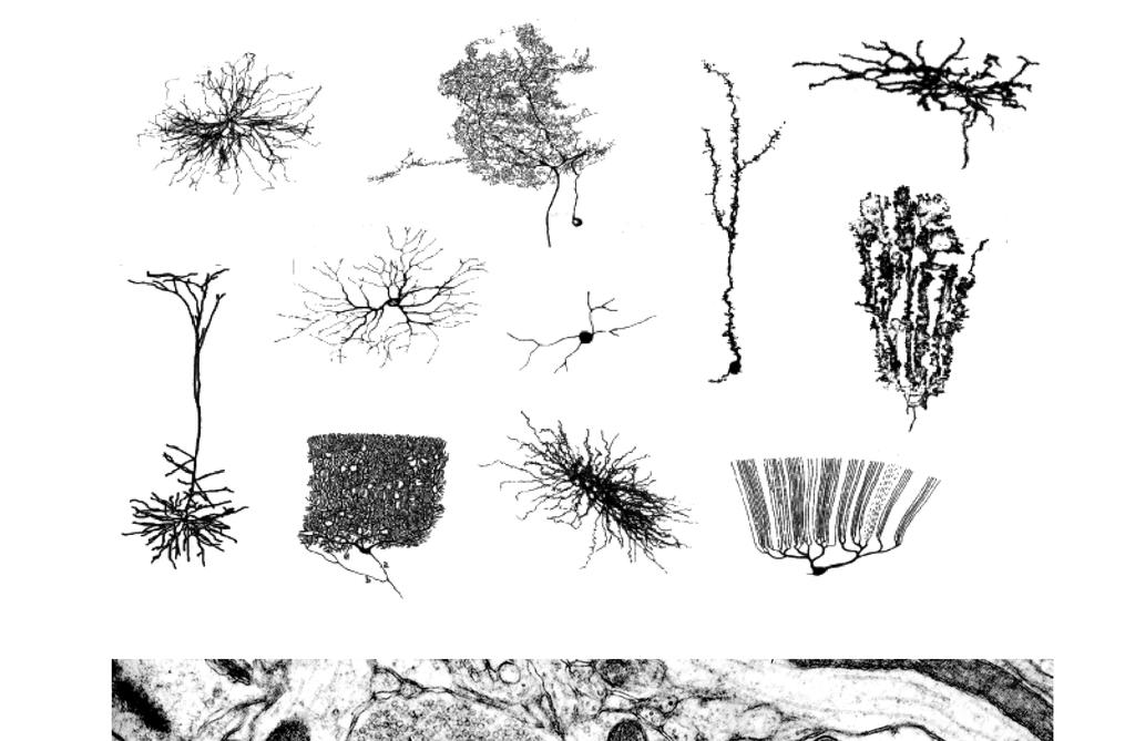
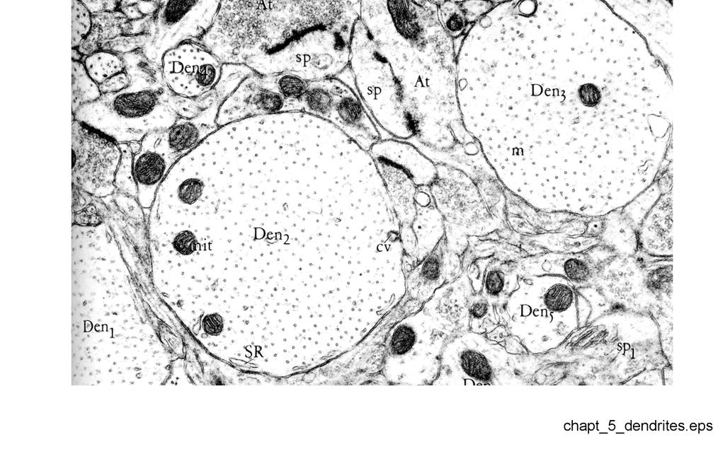
1 Physics 171/271 - Note 3A - David Kleinfeld - Fall Cables: Electrotonic Length, Attenuation, and Filtering We consider, briefly, the behavior of the transmembrane potential across a long process. The cytoplasm acts as one conductor and the extracellular space acts as the second. Let s assume, as is often but not always the case, that the conductance of the extracellular space may be taken as infinite. Then a signal that flows down the center will be attenuated over a length of axon such that the cytoplasmic and membrane impedances (don t forget the capacitance of the membrane) are about equal, i.e., over the length required to form a voltage divider. FIGURE - chapt-5-dendrites.eps 3.1 Basic Scales For an axon of radius a with membrane thickness L, we can estimate this length by equating the cytoplasmic and membrane resistances, i.e., or Usually the product λ ρ c πa ρ L 2 m 2πaλ λ = ρm al ρ c 2 (3.101) (3.102) r m = ρ m L (3.103) is denoted as the specific membrane resistance It has typical values of r m =1 to 100 kωcm 2, while the cytoplasm has resistances of order ρ c = 30 to 300 Ωcm. The spatial attenuation length λ is seen to vary as λ a 1/ Cable Equation We can now just consider a model with resistances and capacitances (inductance is negligable at the 10 khz frequencies of neuronal operation) and write down a lumped parameter model for a lossy cable. The exact equation for a cable can be considered by writing the circuit equations for a segment of length x and letting x 0. We get τ V (x, t) t + V (x, t) λ 2 2 V (x, t) x 2 = r m 2πa I m(x, t) (3.104) 1
2 We have included the possibility of additional membrane currents, denoted I m in units of Amperes per unit length; these will become evident when we study action potential propagation. FIGURE - chapt-5-linear-cable.eps Steady State Response A particularly simple case to consider is the steady state response to the continuous injection of current at a point. The cable equation turns into Helmholtz s equation (λ plays the role of k ), i.e., V (x) λ 2 2 V (x) = r m x 2 2πa I m(x) (3.105) and we know that the solutions are of the form V (x) = Ae x λ + Be x λ + C (3.106) where here the A, B, Cs are constants. For the case of current injected at a spot into an infinitely long uniform cable,, i.e, I m (x) = I o δ(x), the change in voltage is r m FIGURE - chapt-5-steady-state-dc.eps V (x) = I o x 2λ 2πa e λ + V ( ) (3.107) Thus, as we claimed above, we see directly that λ scales the length of the electrical disturbance. We also see that the input resistance scales as R = V (0) 2 = ρc r m a 3/2 (3.108) I o 4π Thus the resistance goes up faster than linear as the radius of the process decreases. To the extent that large resistances are a good thing, as least as far as not loading down the soma, one cannot be too thin.... We can push this result into the frequency domain to see what the low pass filtering characteristics of the cable look like. The simplest way to do this is to take the Fourier transform, with respect to time, of the original cable equation. We get or iτωṽ (x, ω) + Ṽ (x, ω) λ2 2 Ṽ (x, ω) x 2 = r m 2πaĨm(x, ω) (3.109) (1 + iωτ)ṽ (x, ω) Ṽ (x, ω) λ2 2 = r m x 2 2πaĨm(x, ω) (3.110) This looks exactly like the Helmholtz equation if we make the substitutions r m r m 1 + iωτ (3.111) 2
3 λ r m 1 + iωτ (3.112) The resistance is generalized to a steady-state impedance with 1 Z(ω) = R = R e i 2 tan 1 (ωτ) 1 + iωτ (1 + (ωτ) 2 ) 1 4 (3.113) It is interesting that the impedance varies as Z R/ ωτ, in contrast to the Z R/(ωτ) dependence for a lumped RC circuit. This was recently seen in motoneurons. Thus long cables provide a very soft filtering effect. FIGURE - chapt-5-facial-motoneurons.eps General Response The full cable equation is simple to evaluate once you realize that this is really the diffusion equation in terms of the function U(x, t), with V (x, t) = e t τ U(x, t) (3.114) where λ2 ρ cc m plays the role of the diffusion constant. The homogeneous part of the cable equation becomes τ = a λ 2 2 U(x, t) U(x, t) τ = 0 (3.115) x 2 t We can write down the delta function response directly. That is, for an impulse of charge so that I m (x, t) = Q o δ(x)δ(t), the voltage evolves as V (x, t) = Q o r m τ t τ 2πa 4πλ 2 t e τ x2 τ 4λ 2 t (3.116) There are two essential aspects of the response to consider. The first is that the voltage at the injection site initially decay faster than τ m as current flows into the cable and and charge it. At later times all locations of the cable essentially discharge together and the decay is exponential. This behavior can be seen from plots of the calculated response at various distances from the origin, and in the data of Rall, who spent much effort on the issue of cables. FIGURE - chapt-5-cable-solutions.eps FIGURE - chapt-5-cable-decay.eps The second point is that the pulse is decaying as it spreads, and thus has the appearance of a front. We can ask where the front of the pulse is by calculating V (x,t) = 0. We rewrite our solution of the cable equation with all of the time and t space dependent terms in the exponent, so that V (x, t) = V (0)e 1 2 ln t τ t τ x2 τ 4λ 2 t (3.117) 3
4 Thus V (x,t) t = Voef(x,t) t = V o e f(x,t) f(x,t) t = 0 implies which gives d ( 1 ln t + t + ) x2 τ 2 τ τ 4λ 2 t dt t τ 2 + t2 x2 τ 2 t max = τ x2 λ 1 τ = 0 (3.118) 4λ 2 = 0 (3.119) x λ (3.120) The ratio x t max = 2λ τ is the speed of the peak of the voltage pulse. 4
5
6
7
8
9
10
11
Quantitative Electrophysiology
 ECE 795: Quantitative Electrophysiology Notes for Lecture #4 Wednesday, October 4, 2006 7. CHEMICAL SYNAPSES AND GAP JUNCTIONS We will look at: Chemical synapses in the nervous system Gap junctions in
BENG 221 Mathematical Methods in Bioengineering. Fall 2017 Midterm
 BENG Mathematical Methods in Bioengineering Fall 07 Midterm NAME: Open book, open notes. 80 minutes limit (end of class). No communication other than with instructor and TAs. No computers or internet,
80% of all excitatory synapses - at the dendritic spines.
 Dendritic Modelling Dendrites (from Greek dendron, tree ) are the branched projections of a neuron that act to conduct the electrical stimulation received from other cells to and from the cell body, or
Lecture 10 : Neuronal Dynamics. Eileen Nugent
 Lecture 10 : Neuronal Dynamics Eileen Nugent Origin of the Cells Resting Membrane Potential: Nernst Equation, Donnan Equilbrium Action Potentials in the Nervous System Equivalent Electrical Circuits and
Basics of Network Theory (Part-I)
") Basics of Network Theory (Part-I) 1. One coulomb charge is equal to the charge on (a) 6.24 x 10 18 electrons (b) 6.24 x 10 24 electrons (c) 6.24 x 10 18 atoms (d) none of the above 2. The correct relation
Basics of Network Theory (Part-I) 1. One coulomb charge is equal to the charge on (a) 6.24 x 10 18 electrons (b) 6.24 x 10 24 electrons (c) 6.24 x 10 18 atoms (d) none of the above 2. The correct relation
Passive Membrane Properties
 Passive Membrane Properties Communicating through a leaky garden hose... Topics I Introduction & Electrochemical Gradients Passive Membrane Properties Action Potentials Voltage-Gated Ion Channels Topics
EE292: Fundamentals of ECE
 EE292: Fundamentals of ECE Fall 2012 TTh 10:00-11:15 SEB 1242 Lecture 14 121011 http://www.ee.unlv.edu/~b1morris/ee292/ 2 Outline Review Steady-State Analysis RC Circuits RL Circuits 3 DC Steady-State
Electrical Circuits (2)
") Electrical Circuits (2) Lecture 7 Transient Analysis Dr.Eng. Basem ElHalawany Extra Reference for this Lecture Chapter 16 Schaum's Outline Of Theory And Problems Of Electric Circuits https://archive.org/details/theoryandproblemsofelectriccircuits
Electrical Circuits (2) Lecture 7 Transient Analysis Dr.Eng. Basem ElHalawany Extra Reference for this Lecture Chapter 16 Schaum's Outline Of Theory And Problems Of Electric Circuits https://archive.org/details/theoryandproblemsofelectriccircuits
3 Action Potentials - Brutal Approximations
 Physics 172/278 - David Kleinfeld - Fall 2004; Revised Winter 2015 3 Action Potentials - Brutal Approximations The Hodgkin-Huxley equations for the behavior of the action potential in squid, and similar
Do not fill out the information below until instructed to do so! Name: Signature: Section Number:
 Do not fill out the information below until instructed to do so! Name: Signature: E-mail: Section Number: No calculators are allowed in the test. Be sure to put a box around your final answers and clearly
PHY3128 / PHYM203 (Electronics / Instrumentation) Transmission Lines
 Transmission Lines") Transmission Lines Introduction A transmission line guides energy from one place to another. Optical fibres, waveguides, telephone lines and power cables are all electromagnetic transmission lines. are
Transmission Lines Introduction A transmission line guides energy from one place to another. Optical fibres, waveguides, telephone lines and power cables are all electromagnetic transmission lines. are
Kimmo Silvonen, Transmission lines, ver
 Kimmo Silvonen, Transmission lines, ver. 13.10.2008 1 1 Basic Theory The increasing operating and clock frequencies require transmission line theory to be considered more and more often! 1.1 Some practical
Chapter 4 Transients. Chapter 4 Transients
 Chapter 4 Transients Chapter 4 Transients 1. Solve first-order RC or RL circuits. 2. Understand the concepts of transient response and steady-state response. 1 3. Relate the transient response of first-order
Inductive & Capacitive Circuits. Subhasish Chandra Assistant Professor Department of Physics Institute of Forensic Science, Nagpur
 Inductive & Capacitive Circuits Subhasish Chandra Assistant Professor Department of Physics Institute of Forensic Science, Nagpur LR Circuit LR Circuit (Charging) Let us consider a circuit having an inductance
Physics 220: Worksheet 7
 (1 A resistor R 1 =10 is connected in series with a resistor R 2 =100. A current I=0.1 A is present through the circuit. What is the power radiated in each resistor and also in the total circuit? (2 A
ENERGY AND TIME CONSTANTS IN RC CIRCUITS By: Iwana Loveu Student No Lab Section: 0003 Date: February 8, 2004
 ENERGY AND TIME CONSTANTS IN RC CIRCUITS By: Iwana Loveu Student No. 416 614 5543 Lab Section: 0003 Date: February 8, 2004 Abstract: Two charged conductors consisting of equal and opposite charges forms
Some of the different forms of a signal, obtained by transformations, are shown in the figure. jwt e z. jwt z e
 Transform methods Some of the different forms of a signal, obtained by transformations, are shown in the figure. X(s) X(t) L - L F - F jw s s jw X(jw) X*(t) F - F X*(jw) jwt e z jwt z e X(nT) Z - Z X(z)
25.2. Applications of PDEs. Introduction. Prerequisites. Learning Outcomes
 Applications of PDEs 25.2 Introduction In this Section we discuss briefly some of the most important PDEs that arise in various branches of science and engineering. We shall see that some equations can
Bo Deng University of Nebraska-Lincoln UNL Math Biology Seminar
 Mathematical Model of Neuron Bo Deng University of Nebraska-Lincoln UNL Math Biology Seminar 09-10-2015 Review -- One Basic Circuit By Kirchhoff's Current Law 0 = I C + I R + I L I ext By Kirchhoff s Voltage
Equivalent Circuit Model of the Neuron
 Generator Potentials, Synaptic Potentials and Action Potentials All Can Be Described by the Equivalent Circuit Model of the Membrane Equivalent Circuit Model of the Neuron PNS, Fig 211 The Nerve (or Muscle)
Modeling of Retinal Ganglion Cell Responses to Electrical Stimulation with Multiple Electrodes L.A. Hruby Salk Institute for Biological Studies
 Modeling of Retinal Ganglion Cell Responses to Electrical Stimulation with Multiple Electrodes L.A. Hruby Salk Institute for Biological Studies Introduction Since work on epiretinal electrical stimulation
SECOND PUBLIC EXAMINATION. Honour School of Physics Part C: 4 Year Course. Honour School of Physics and Philosophy Part C C7: BIOLOGICAL PHYSICS
 2757 SECOND PUBLIC EXAMINATION Honour School of Physics Part C: 4 Year Course Honour School of Physics and Philosophy Part C C7: BIOLOGICAL PHYSICS TRINITY TERM 2013 Monday, 17 June, 2.30 pm 5.45 pm 15
Basic elements of neuroelectronics -- membranes -- ion channels -- wiring
 Computing in carbon Basic elements of neuroelectronics -- membranes -- ion channels -- wiring Elementary neuron models -- conductance based -- modelers alternatives Wires -- signal propagation -- processing
The (Fast) Fourier Transform
 Fourier Transform") The (Fast) Fourier Transform The Fourier transform (FT) is the analog, for non-periodic functions, of the Fourier series for periodic functions can be considered as a Fourier series in the limit that the
The (Fast) Fourier Transform The Fourier transform (FT) is the analog, for non-periodic functions, of the Fourier series for periodic functions can be considered as a Fourier series in the limit that the
Name. Section. Short Answer Questions. 1. (20 Pts) 2. (10 Pts) 3. (5 Pts) 4. (10 Pts) 5. (10 Pts) Regular Questions. 6. (25 Pts) 7.
 2. (10 Pts) 3. (5 Pts) 4. (10 Pts) 5. (10 Pts) Regular Questions. 6. (25 Pts) 7.") Name Section Short Answer Questions 1. (20 Pts) 2. (10 Pts) 3. (5 Pts). (10 Pts) 5. (10 Pts) Regular Questions 6. (25 Pts) 7. (20 Pts) Notes: 1. Please read over all questions before you begin your work.
Name Section Short Answer Questions 1. (20 Pts) 2. (10 Pts) 3. (5 Pts). (10 Pts) 5. (10 Pts) Regular Questions 6. (25 Pts) 7. (20 Pts) Notes: 1. Please read over all questions before you begin your work.
Determining Characteristic Impedance and Velocity of Propagation by Measuring the Distributed Capacitance and Inductance of a Line
 Exercise 2-1 Determining Characteristic Impedance and Velocity EXERCISE OBJECTIVES Upon completion of this exercise, you will know how to measure the distributed capacitance and distributed inductance
Physics 115. General Physics II. Session 24 Circuits Series and parallel R Meters Kirchoff s Rules
 Physics 115 General Physics II Session 24 Circuits Series and parallel R Meters Kirchoff s Rules R. J. Wilkes Email: phy115a@u.washington.edu Home page: http://courses.washington.edu/phy115a/ 5/15/14 Phys
Integration of synaptic inputs in dendritic trees
 Integration of synaptic inputs in dendritic trees Theoretical Neuroscience Fabrizio Gabbiani Division of Neuroscience Baylor College of Medicine One Baylor Plaza Houston, TX 77030 e-mail:gabbiani@bcm.tmc.edu
Chapter 18 Electric Currents
 Chapter 18 Electric Currents 1 The Electric Battery Volta discovered that electricity could be created if dissimilar metals were connected by a conductive solution called an electrolyte. This is a simple
Lecture 27 Frequency Response 2
 Lecture 27 Frequency Response 2 Fundamentals of Digital Signal Processing Spring, 2012 Wei-Ta Chu 2012/6/12 1 Application of Ideal Filters Suppose we can generate a square wave with a fundamental period
Transmission lines. Shouri Chatterjee. October 22, 2014
 Transmission lines Shouri Chatterjee October 22, 2014 The transmission line is a very commonly used distributed circuit: a pair of wires. Unfortunately, a pair of wires used to apply a time-varying voltage,
Time Domain Reflectometry Theory
 Time Domain Reflectometry Theory Application Note 304-2 For Use with Agilent 8600B Infiniium DCA Introduction The most general approach to evaluating the time domain response of any electromagnetic system
Prof. Anyes Taffard. Physics 120/220. Voltage Divider Capacitor RC circuits
 Prof. Anyes Taffard Physics 120/220 Voltage Divider Capacitor RC circuits Voltage Divider The figure is called a voltage divider. It s one of the most useful and important circuit elements we will encounter.
Inductance. thevectorpotentialforthemagneticfield, B 1. ] d l 2. 4π I 1. φ 12 M 12 I 1. 1 Definition of Inductance. r 12
![Inductance. thevectorpotentialforthemagneticfield, B 1. ] d l 2. 4π I 1. φ 12 M 12 I 1. 1 Definition of Inductance. r 12](/thumbs/72/67161747.jpg "Inductance. thevectorpotentialforthemagneticfield, B 1. ] d l 2. 4π I 1. φ 12 M 12 I 1. 1 Definition of Inductance. r 12") Inductance 1 Definition of Inductance When electric potentials are placed on a system of conductors, charges move to cancel the electric field parallel to the conducting surfaces of the conductors. We
Inductance 1 Definition of Inductance When electric potentials are placed on a system of conductors, charges move to cancel the electric field parallel to the conducting surfaces of the conductors. We
Channels can be activated by ligand-binding (chemical), voltage change, or mechanical changes such as stretch.
, voltage change, or mechanical changes such as stretch.") 1. Describe the basic structure of an ion channel. Name 3 ways a channel can be "activated," and describe what occurs upon activation. What are some ways a channel can decide what is allowed to pass through?
1. Describe the basic structure of an ion channel. Name 3 ways a channel can be "activated," and describe what occurs upon activation. What are some ways a channel can decide what is allowed to pass through?
AC Circuits Homework Set
 Problem 1. In an oscillating LC circuit in which C=4.0 μf, the maximum potential difference across the capacitor during the oscillations is 1.50 V and the maximum current through the inductor is 50.0 ma.
Chapter 26 & 27. Electric Current and Direct- Current Circuits
 Chapter 26 & 27 Electric Current and Direct- Current Circuits Electric Current and Direct- Current Circuits Current and Motion of Charges Resistance and Ohm s Law Energy in Electric Circuits Combination
2005 AP PHYSICS C: ELECTRICITY AND MAGNETISM FREE-RESPONSE QUESTIONS
 2005 AP PHYSICS C: ELECTRICITY AND MAGNETISM In the circuit shown above, resistors 1 and 2 of resistance R 1 and R 2, respectively, and an inductor of inductance L are connected to a battery of emf e and
Conventional Paper-I Part A. 1. (a) Define intrinsic wave impedance for a medium and derive the equation for intrinsic vy
 Define intrinsic wave impedance for a medium and derive the equation for intrinsic vy") EE-Conventional Paper-I IES-01 www.gateforum.com Conventional Paper-I-01 Part A 1. (a) Define intrinsic wave impedance for a medium and derive the equation for intrinsic vy impedance for a lossy dielectric
EE-Conventional Paper-I IES-01 www.gateforum.com Conventional Paper-I-01 Part A 1. (a) Define intrinsic wave impedance for a medium and derive the equation for intrinsic vy impedance for a lossy dielectric
ELECTRICAL STIMULATION OF EXCITABLE TISSUE
 7 ELECTRICAL STIMULATION OF EXCITABLE TISSUE In designing systems for stimulation, a qualitative understanding together with mathematical descriptions of responses to stimulation are essential. The response
Module 2 : Transmission Lines. Lecture 1 : Transmission Lines in Practice. Objectives. In this course you will learn the following
 Objectives In this course you will learn the following Point 1 Point 2 Point 3 Point 4 Point 5 Point 6 Point 7 Point 8 Point 9 Point 10 Point 11 Point 12 Various Types Of Transmission Line Explanation:
Graduate Diploma in Engineering Circuits and waves
 9210-112 Graduate Diploma in Engineering Circuits and waves You should have the following for this examination one answer book non-programmable calculator pen, pencil, ruler No additional data is attached
Transmission Lines, Stacked Insulated Washers Lines, Tesla Coils and the Telegrapher s Equation
 Transmission Lines, Stacked Insulated Washers Lines, Tesla oils and the Telegrapher s Equation Kurt Nalty August, 2008 Abstract Tesla coils have more in common with transmission lines than transformers.
Introduction to Neural Networks U. Minn. Psy 5038 Spring, 1999 Daniel Kersten. Lecture 2a. The Neuron - overview of structure. From Anderson (1995)
") Introduction to Neural Networks U. Minn. Psy 5038 Spring, 1999 Daniel Kersten Lecture 2a The Neuron - overview of structure From Anderson (1995) 2 Lect_2a_Mathematica.nb Basic Structure Information flow:
Introduction to Neural Networks U. Minn. Psy 5038 Spring, 1999 Daniel Kersten Lecture 2a The Neuron - overview of structure From Anderson (1995) 2 Lect_2a_Mathematica.nb Basic Structure Information flow:
Chapter 5 Frequency Domain Analysis of Systems
 Chapter 5 Frequency Domain Analysis of Systems CT, LTI Systems Consider the following CT LTI system: xt () ht () yt () Assumption: the impulse response h(t) is absolutely integrable, i.e., ht ( ) dt< (this
BIOELECTRIC PHENOMENA
 Chapter 11 BIOELECTRIC PHENOMENA 11.3 NEURONS 11.3.1 Membrane Potentials Resting Potential by separation of charge due to the selective permeability of the membrane to ions From C v= Q, where v=60mv and
Total No. of Questions :09] [Total No. of Pages : 03
![Total No. of Questions :09] [Total No. of Pages : 03](/thumbs/94/118747664.jpg "Total No. of Questions :09] [Total No. of Pages : 03") EE 4 (RR) Total No. of Questions :09] [Total No. of Pages : 03 II/IV B.Tech. DEGREE EXAMINATIONS, APRIL/MAY- 016 Second Semester ELECTRICAL & ELECTRONICS NETWORK ANALYSIS Time: Three Hours Answer Question
EE 4 (RR) Total No. of Questions :09] [Total No. of Pages : 03 II/IV B.Tech. DEGREE EXAMINATIONS, APRIL/MAY- 016 Second Semester ELECTRICAL & ELECTRONICS NETWORK ANALYSIS Time: Three Hours Answer Question
ECE2262 Electric Circuits. Chapter 6: Capacitance and Inductance
 ECE2262 Electric Circuits Chapter 6: Capacitance and Inductance Capacitors Inductors Capacitor and Inductor Combinations Op-Amp Integrator and Op-Amp Differentiator 1 CAPACITANCE AND INDUCTANCE Introduces
Lecture 6: Impedance (frequency dependent. resistance in the s- world), Admittance (frequency. dependent conductance in the s- world), and
, Admittance (frequency. dependent conductance in the s- world), and") Lecture 6: Impedance (frequency dependent resistance in the s- world), Admittance (frequency dependent conductance in the s- world), and Consequences Thereof. Professor Ray, what s an impedance? Answers:
Lecture 6: Impedance (frequency dependent resistance in the s- world), Admittance (frequency dependent conductance in the s- world), and Consequences Thereof. Professor Ray, what s an impedance? Answers:
arxiv: v2 [q-bio.nc] 10 Oct 2014
![arxiv: v2 [q-bio.nc] 10 Oct 2014](/thumbs/87/97075491.jpg "arxiv: v2 [q-bio.nc] 10 Oct 2014") Generalized cable formalism to calculate the magnetic field of single neurons and neuronal populations Claude Bedard and Alain Destexhe arxiv:147.248v2 [q-bio.nc] 1 Oct 214 Abstract Physical Review E,
Generalized cable formalism to calculate the magnetic field of single neurons and neuronal populations Claude Bedard and Alain Destexhe arxiv:147.248v2 [q-bio.nc] 1 Oct 214 Abstract Physical Review E,
Yell if you have any questions
 Class 31: Outline Hour 1: Concept Review / Overview PRS Questions possible exam questions Hour : Sample Exam Yell if you have any questions P31 1 Exam 3 Topics Faraday s Law Self Inductance Energy Stored
Chapter 5 Frequency Domain Analysis of Systems
 Chapter 5 Frequency Domain Analysis of Systems CT, LTI Systems Consider the following CT LTI system: xt () ht () yt () Assumption: the impulse response h(t) is absolutely integrable, i.e., ht ( ) dt< (this
Lecture Outline Chapter 21. Physics, 4 th Edition James S. Walker. Copyright 2010 Pearson Education, Inc.
 Lecture Outline Chapter 21 Physics, 4 th Edition James S. Walker Chapter 21 Electric Current and Direct- Current Circuits Units of Chapter 21 Electric Current Resistance and Ohm s Law Energy and Power
AC Circuits. The Capacitor
 The Capacitor Two conductors in close proximity (and electrically isolated from one another) form a capacitor. An electric field is produced by charge differences between the conductors. The capacitance
ELECTROMAGNETISM SUMMARY. Maxwell s equations Transmission lines Transmission line transformers Skin depth
 ELECTROMAGNETISM SUMMARY Maxwell s equations Transmission lines Transmission line transformers Skin depth 1 ENGN4545/ENGN6545: Radiofrequency Engineering L#4 Magnetostatics: The static magnetic field Gauss
Ionic basis of the resting membrane potential. Foundations in Neuroscience I, Oct
 Ionic basis of the resting membrane potential Foundations in Neuroscience I, Oct 3 2017 The next 4 lectures... - The resting membrane potential (today) - The action potential - The neural mechanisms behind
Lab 4 RC Circuits. Name. Partner s Name. I. Introduction/Theory
 Lab 4 RC Circuits Name Partner s Name I. Introduction/Theory Consider a circuit such as that in Figure 1, in which a potential difference is applied to the series combination of a resistor and a capacitor.
University of TN Chattanooga Physics 1040L 8/18/2012 PHYSICS 1040L LAB LAB 4: R.C. TIME CONSTANT LAB
 PHYSICS 1040L LAB LAB 4: R.C. TIME CONSTANT LAB OBJECT: To study the discharging of a capacitor and determine the time constant for a simple circuit. APPARATUS: Capacitor (about 24 μf), two resistors (about
ESE 570: Digital Integrated Circuits and VLSI Fundamentals
 ESE 570: Digital Integrated Circuits and VLSI Fundamentals Lec 24: April 19, 2018 Crosstalk and Wiring, Transmission Lines Lecture Outline! Crosstalk! Repeaters in Wiring! Transmission Lines " Where transmission
0 t < 0 1 t 1. u(t) =
 =") A. M. Niknejad University of California, Berkeley EE 100 / 42 Lecture 13 p. 22/33 Step Response A unit step function is described by u(t) = ( 0 t < 0 1 t 1 While the waveform has an artificial jump (difficult
A. M. Niknejad University of California, Berkeley EE 100 / 42 Lecture 13 p. 22/33 Step Response A unit step function is described by u(t) = ( 0 t < 0 1 t 1 While the waveform has an artificial jump (difficult
! Crosstalk. ! Repeaters in Wiring. ! Transmission Lines. " Where transmission lines arise? " Lossless Transmission Line.
 ESE 570: Digital Integrated Circuits and VLSI Fundamentals Lec 24: April 19, 2018 Crosstalk and Wiring, Transmission Lines Lecture Outline! Crosstalk! Repeaters in Wiring! Transmission Lines " Where transmission
(a) What is the direction of the magnetic field at point P (i.e., into or out of the page), and why?
 What is the direction of the magnetic field at point P (i.e., into or out of the page), and why?") Physics 9 Fall 2010 Midterm 2 s For the midterm, you may use one sheet of notes with whatever you want to put on it, front and back Please sit every other seat, and please don t cheat! If something isn
Physics 9 Fall 2010 Midterm 2 s For the midterm, you may use one sheet of notes with whatever you want to put on it, front and back Please sit every other seat, and please don t cheat! If something isn
Model Neurons II: Conductances and Morphology
 Chapter 6 Model Neurons II: Conductances and Morphology 6.1 Levels of Neuron Modeling In modeling neurons, we must deal with two types of complexity; the intricate interplay of active conductances that
Assessment Schedule 2015 Physics: Demonstrate understanding of electrical systems (91526)
") NCEA Level 3 Physics (91526) 2015 page 1 of 6 Assessment Schedule 2015 Physics: Demonstrate understanding of electrical systems (91526) Evidence Q Evidence Achievement Achievement with Merit Achievement
NCEA Level 3 Physics (91526) 2015 page 1 of 6 Assessment Schedule 2015 Physics: Demonstrate understanding of electrical systems (91526) Evidence Q Evidence Achievement Achievement with Merit Achievement
ELECTRIC CURRENTS D R M A R T A S T A S I A K D E P A R T M E N T O F C Y T O B I O L O G Y A N D P R O T E O M I C S
 ELECTRIC CURRENTS D R M A R T A S T A S I A K D E P A R T M E N T O F C Y T O B I O L O G Y A N D P R O T E O M I C S lecture based on 2016 Pearson Education, Ltd. The Electric Battery Electric Current
9 Generation of Action Potential Hodgkin-Huxley Model
 9 Generation of Action Potential Hodgkin-Huxley Model (based on chapter 12, W.W. Lytton, Hodgkin-Huxley Model) 9.1 Passive and active membrane models In the previous lecture we have considered a passive
EE292: Fundamentals of ECE
 EE292: Fundamentals of ECE Fall 2012 TTh 10:00-11:15 SEB 1242 Lecture 20 121101 http://www.ee.unlv.edu/~b1morris/ee292/ 2 Outline Chapters 1-3 Circuit Analysis Techniques Chapter 10 Diodes Ideal Model
Physics 142 Steady Currents Page 1. Steady Currents
 Physics 142 Steady Currents Page 1 Steady Currents If at first you don t succeed, try, try again. Then quit. No sense being a damn fool about it. W.C. Fields Electric current: the slow average drift of
Biomedical Instrumentation
 ELEC ENG 4BD4: Biomedical Instrumentation Lecture 5 Bioelectricity 1. INTRODUCTION TO BIOELECTRICITY AND EXCITABLE CELLS Historical perspective: Bioelectricity first discovered by Luigi Galvani in 1780s
Conventional Paper I-2010
 Conventional Paper I-010 1. (a) Sketch the covalent bonding of Si atoms in a intrinsic Si crystal Illustrate with sketches the formation of bonding in presence of donor and acceptor atoms. Sketch the energy
Inductors. Hydraulic analogy Duality with capacitor Charging and discharging. Lecture 12: Inductors
 Lecture 12: nductors nductors Hydraulic analogy Duality with capacitor Charging and discharging Robert R. McLeod, University of Colorado http://hilaroad.com/camp/projects/magnet.html 99 Lecture 12: nductors
Lecture 24. Impedance of AC Circuits.
 Lecture 4. Impedance of AC Circuits. Don t forget to complete course evaluations: https://sakai.rutgers.edu/portal/site/sirs Post-test. You are required to attend one of the lectures on Thursday, Dec.
INSTITUTE OF AERONAUTICAL ENGINEERING Dundigal, Hyderabad Electronics and Communicaton Engineering
 INSTITUTE OF AERONAUTICAL ENGINEERING Dundigal, Hyderabad - 00 04 Electronics and Communicaton Engineering Question Bank Course Name : Electromagnetic Theory and Transmission Lines (EMTL) Course Code :
ADMISSION TEST INDUSTRIAL AUTOMATION ENGINEERING
 UNIVERSITÀ DEGLI STUDI DI PAVIA ADMISSION TEST INDUSTRIAL AUTOMATION ENGINEERING September 26, 2016 The candidates are required to answer the following multiple choice test which includes 30 questions;
Physics 116A Notes Fall 2004
 Physics 116A Notes Fall 2004 David E. Pellett Draft v.0.9 Notes Copyright 2004 David E. Pellett unless stated otherwise. References: Text for course: Fundamentals of Electrical Engineering, second edition,
ECE2262 Electric Circuits. Chapter 6: Capacitance and Inductance
 ECE2262 Electric Circuits Chapter 6: Capacitance and Inductance Capacitors Inductors Capacitor and Inductor Combinations 1 CAPACITANCE AND INDUCTANCE Introduces two passive, energy storing devices: Capacitors
Dendritic computation
 Dendritic computation Dendrites as computational elements: Passive contributions to computation Active contributions to computation Examples Geometry matters: the isopotential cell Injecting current I
ECE 6340 Fall Homework 2. Please do the following problems (you may do the others for practice if you wish): Probs. 1, 2, 3, 4, 5, 6, 7, 10, 12
: Probs. 1, 2, 3, 4, 5, 6, 7, 10, 12") ECE 634 Fall 16 Homework Please do the following problems (you may do the others for practice if you wish: Probs. 1,, 3, 4, 5, 6, 7, 1, 1 1 Consider two parallel infinite wires in free space each carrying
ECE 634 Fall 16 Homework Please do the following problems (you may do the others for practice if you wish: Probs. 1,, 3, 4, 5, 6, 7, 1, 1 1 Consider two parallel infinite wires in free space each carrying
Magnetic Field Penetration Into a Conducting Hohlraum
 Kirkley, Alec 1 Magnetic Field Penetration Into a Conducting Hohlraum Alec Kirkley Pittsford Sutherland High School Pittsford, NY Advisor: Dr. Gennady Fiksel Laboratory for Laser Energetics University
Magnetotelluric (MT) Method
 Method") Magnetotelluric (MT) Method Dr. Hendra Grandis Graduate Program in Applied Geophysics Faculty of Mining and Petroleum Engineering ITB Geophysical Methods Techniques applying physical laws (or theory) to
Magnetotelluric (MT) Method Dr. Hendra Grandis Graduate Program in Applied Geophysics Faculty of Mining and Petroleum Engineering ITB Geophysical Methods Techniques applying physical laws (or theory) to
Effective Design of Large Grounding Systems
 Effective Design of Large Grounding Systems Lorentzou M.I. Hatziargyriou N.D. National Technical University of Athens Department of Electrical Engineering 9 Heroon Politechniou, Zografou Campus, Athens,
Νευροφυσιολογία και Αισθήσεις
 Biomedical Imaging & Applied Optics University of Cyprus Νευροφυσιολογία και Αισθήσεις Διάλεξη 5 Μοντέλο Hodgkin-Huxley (Hodgkin-Huxley Model) Response to Current Injection 2 Hodgin & Huxley Sir Alan Lloyd
ES 272 Assignment #2. in,3
 ES 272 Assignment #2 Due: March 14th, 2014; 5pm sharp, in the dropbox outside MD 131 (Donhee Ham office) Instructor: Donhee Ham (copyright c 2014 by D. Ham) (Problem 1) The kt/c Noise (50pt) Imagine an
NE 204 mini-syllabus (weeks 4 8)
") NE 24 mini-syllabus (weeks 4 8) Instructor: John Burke O ce: MCS 238 e-mail: jb@math.bu.edu o ce hours: by appointment Overview: For the next few weeks, we will focus on mathematical models of single neurons.
NE 24 mini-syllabus (weeks 4 8) Instructor: John Burke O ce: MCS 238 e-mail: jb@math.bu.edu o ce hours: by appointment Overview: For the next few weeks, we will focus on mathematical models of single neurons.
1.3 Sinusoidal Steady State
 1.3 Sinusoidal Steady State Electromagnetics applications can be divided into two broad classes: Time-domain: Excitation is not sinusoidal (pulsed, broadband, etc.) Ultrawideband communications Pulsed
The RC Time Constant
 The RC Time Constant Objectives When a direct-current source of emf is suddenly placed in series with a capacitor and a resistor, there is current in the circuit for whatever time it takes to fully charge
Phys498BIO; Prof. Paul Selvin Hw #9 Assigned Wed. 4/18/12: Due 4/25/08
 1. Ionic Movements Across a Permeable Membrane: The Nernst Potential. In class we showed that if a non-permeable membrane separates a solution with high [KCl] from a solution with low [KCl], the net charge
Transmission Line Basics II - Class 6
 Transmission Line Basics II - Class 6 Prerequisite Reading assignment: CH2 Acknowledgements: Intel Bus Boot Camp: Michael Leddige Agenda 2 The Transmission Line Concept Transmission line equivalent circuits
Module 4. Single-phase AC Circuits
 Module 4 Single-phase AC Circuits Lesson 14 Solution of Current in R-L-C Series Circuits In the last lesson, two points were described: 1. How to represent a sinusoidal (ac) quantity, i.e. voltage/current
PHYS 1441 Section 001 Lecture #23 Monday, Dec. 4, 2017
 PHYS 1441 Section 1 Lecture #3 Monday, Dec. 4, 17 Chapter 3: Inductance Mutual and Self Inductance Energy Stored in Magnetic Field Alternating Current and AC Circuits AC Circuit W/ LRC Chapter 31: Maxwell
Question 1. Question 2. Question 3
 Question 1 Switch S in in the figure is closed at time t = 0, to begin charging an initially uncharged capacitor of capacitance C = 18.2 μf through a resistor of resistance R = 22.3 Ω. At what time (in
Transmission Lines. Transformation of voltage, current and impedance. Impedance. Application of transmission lines
 Transmission Lines Transformation of voltage, current and impedance Impedance Application of transmission lines 1 ENGN4545/ENGN6545: Radiofrequency Engineering L#21 The Telegraphist Equations We can rewrite
Magnetic Fields; Sources of Magnetic Field
 This test covers magnetic fields, magnetic forces on charged particles and current-carrying wires, the Hall effect, the Biot-Savart Law, Ampère s Law, and the magnetic fields of current-carrying loops
Electrical Circuits Lab Series RC Circuit Phasor Diagram
 Electrical Circuits Lab. 0903219 Series RC Circuit Phasor Diagram - Simple steps to draw phasor diagram of a series RC circuit without memorizing: * Start with the quantity (voltage or current) that is
ELECTROMAGNETIC OSCILLATIONS AND ALTERNATING CURRENT
 Chapter 31: ELECTROMAGNETIC OSCILLATIONS AND ALTERNATING CURRENT 1 A charged capacitor and an inductor are connected in series At time t = 0 the current is zero, but the capacitor is charged If T is the
Electric Circuits. Overview. Hani Mehrpouyan,
 Electric Circuits Hani Mehrpouyan, Department of Electrical and Computer Engineering, Lecture 15 (First Order Circuits) Nov 16 th, 2015 Hani Mehrpouyan (hani.mehr@ieee.org) Boise State c 2015 1 1 Overview
 Alternating Currents. The power is transmitted from a power house on high voltage ac because (a) Electric current travels faster at higher volts (b) It is more economical due to less power wastage (c)
Version 001 CIRCUITS holland (1290) 1
 1") Version CIRCUITS holland (9) This print-out should have questions Multiple-choice questions may continue on the next column or page find all choices before answering AP M 99 MC points The power dissipated
Version CIRCUITS holland (9) This print-out should have questions Multiple-choice questions may continue on the next column or page find all choices before answering AP M 99 MC points The power dissipated
Basic Electronics. Introductory Lecture Course for. Technology and Instrumentation in Particle Physics Chicago, Illinois June 9-14, 2011
 Basic Electronics Introductory Lecture Course for Technology and Instrumentation in Particle Physics 2011 Chicago, Illinois June 9-14, 2011 Presented By Gary Drake Argonne National Laboratory Session 2
General Appendix A Transmission Line Resonance due to Reflections (1-D Cavity Resonances)
") A 1 General Appendix A Transmission Line Resonance due to Reflections (1-D Cavity Resonances) 1. Waves Propagating on a Transmission Line General A transmission line is a 1-dimensional medium which can
A 1 General Appendix A Transmission Line Resonance due to Reflections (1-D Cavity Resonances) 1. Waves Propagating on a Transmission Line General A transmission line is a 1-dimensional medium which can