Rapid Prototyping for Aerospace Launch Vehicles
|
|
|
- Miranda Phelps
- 5 years ago
- Views:
Transcription
1 Rapid Prototyping for Aerospace Launch Vehicles K. Siva Prasad *, E.Rathakrishnan +, Sanjay.G.Dhande * * Department of Mechanical engineering, IIT-Kanpur, India + Department of Aerospace Engineering, IIT-Kanpur, India Reviewed, accepted August 28, 2003 Abstract Initial studies of the aerodynamic characteristics of proposed launch vehicles can be made more accurately if lower cost, high-fidelity aerodynamic models are available for wind tunnel testing early in design phase. Rapid Prototyping (RP) is an emerging key technology for producing accurate parts directly from CAD models quickly, with little need of human intervention. Use of RP models was studied at the NASA Marshall Space Flight Center (MSFC). It was concluded that RP methods and materials can be used only for preliminary design studies and limited configurations because of the RP material properties that allow bending of models under higher loading conditions. The reported results and analysis were based on wind tunnel balances. These balances give total load on the body. Thus, there is a need for studying the pressure distribution, the wave pattern and the system behavior under high-speed conditions. In order to study the above goals, a blunt nose cone of a launch vehicle/ missile was tested which was made using the solid based RP method FDM, with a Mach number of 2.0. It is concluded that RP models can take the load at the Mach number 2.0 and also can capture the pressure distribution and wave pattern. 1. Introduction Since ancient times, making and testing of prototype is a usual practice before going to the final production. Especially in aerospace industry, this is a crucial stage because one can get the aerodynamic characteristics of the proposed launch vehicle. The fabrication of these prototypes is experimented with many forms like material removal process, castings, injection molding etc. Before 1980, the techniques used making of prototypes were craft based and extremely labor intensive. In early 1980 s the concept of prototyping had changed slightly called soft or virtual prototyping. The models can be made virtually and these can be stressed, tested, analyzed and modified as if they were physical prototypes. In addition, prototypes tend to become relatively more complex about twice the complexity as before Correspondingly, the time required to make physical models increased tremendously but the building of physical prototype still depended on craft based methods in spite of the introduction of better precision machines (like CNC machines). In mid 1980 s the key prototyping technology called Rapid Prototyping (RP) evolved to speed up the prototype manufacturing process. RP is a term, which embraces a range of new technologies for producing accurate parts directly from CAD models with a little need of human intervention. RP of physical parts is also known as solid free form fabrication (SFF), desktop manufacturing or layer manufacturing technology. Till today, making 375
2 376
 format in the CAD systems and sent to the FDM slicing software, called Quick Slice.")
 that contains actual instructions for the FDM machine.")
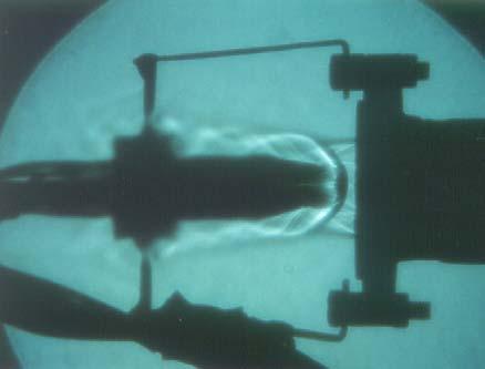
3 A blunt nose cone body has been chosen for the present study. The model (shown in Fig. 1, L ref = 60 mm, S ref = 314 mm 2 ) is made out of a solid based RP method FDM (Fused Deposition Modeling). The 3D model is converted into STL (Stereolithography) format in the CAD systems and sent to the FDM slicing software, called Quick Slice. There the STL file is sliced into thincross sections of desired thickness, creating a.slc file (Slice format file). Supports are created for overhanging parts and sliced as well. The sliced model and support are converted into a.sml file (Stratasys Machine Language) that contains actual instructions for the FDM machine. A tool path is generated which is followed by the numerically controlled extruder head. As the head moves in X and Y- directions following the tool path, the thermoplastic material is extruded out of a nozzle and then deposited in ultra thin layers, one layer at a time. Since the envelope surrounding the head is maintained at a temperature below the melting point of material, the extruded material quickly solidifies [3, 4]. The extruder head has two nozzles, one for the part material and the other for the support material. The support can be easily removed by breaking away. The part is built on a foam foundation attached on a Z-stage platen. The Z-stage platen moves downwards as the part is built progressively. 4. Test Facility Fig. 2 Open Jet Facility at I.I.T-Kanpur, India Fig. 3. Model Mounted on Wind tunnel The experiments were conducted in the jet facility at High speed Aerodynamics Laboratory, Indian Institute of Technology Kanpur, India. The test facility consists of compressor, storage tanks and jet test facility as shown in Fig. 2. A two - stage reciprocating compressor capable of delivering 360 cfm of air at a pressure of 500 psi is used in this laboratory. The compressed air is then passed through a pre-filter consisting of porous stone candles to remove solid contaminates, like rust particles and oil droplets. An activated carbon filter is used for finer filtering. The compressed air is dried in a dual tower semi-automatic silica gel driver. While one tower is in use, a portion of the dried air is heated and used to reactivate the other. A diaphragm type back pressure valve operated by pressure relief pilot permits the dryer to operate at 500 psi, while the pressure in the storage tank builds up from atmospheric to storage pressure. The compressed air is stored in three tanks, having a total capacity of 300 ft 3 at 300 psi. The pitot pressure sensed by the probe was measured using a PSI model 9010, 16-channel 377
4 pressure transducer (interfaced with a PC386). The model 9010 transducer is capable of measuring pressure up to 300 psig, which is approximately 20 atm. The accuracy of the transducer (after rezero calibration) is specified to be 0.15% full scale. 5. Flow Structure The kinetic theory says that flow consists of a large number of fluid molecules in unit volume and the transport of mass, momentum and energy takes place through the motion of these molecules. Also, the molecules carry the signals about the presence of the disturbance around the flow field at a speed equal to speed of sound. When the incoming stream is subsonic i.e. the flow speed is less than the speed of sound and the molecules far upstream of the cylinder get the information about the presence of the body through the signals which travel with speed, a well in advance before reaching the cylinder. Therefore, the molecules orient themselves in order to flow around the cylinder. But when the incoming stream is supersonic, the molecules travel faster than the signals, and there is no possibility that they will be informed of the presence of the body, before they reach the cylinder. Also, the reflected signals from the face of the cylinder tend to coalesce a short distance ahead of the body. Their coalescence forms a thin compression front called shock wave (as shown in Fig. 4). Fig. 4 Physical Significance of the Flow In the flow process, across the front results in an abrupt change in fluid properties. The thickness of the shock is comparable to the mean free path of the gas molecules in the flow field. The formation of shock takes place after the fluid molecules impinge on the face of the cylinder and rebound. The shock formed normal to the flow direction is called normal shock. The compression wave inclined to at an angle to the flow is called oblique shock. So, the normal shock is a special case of oblique shock. Upstream of the shock, the flow has no information about the presence of the body. However, the streamlines behind the normal shock quickly 378
5 compensate for the obstruction, since the flow is subsonic after a normal shock [5]. Oblique shocks usually occur when a flow is turned into itself i.e. when a supersonic flow is turned away from itself, results in the formation of an expansion fan. The flow is deflected into itself by the oblique shock. All the streamliners are deflected to the same angle at the shock, resulting in an uniform parallel flow downstream of shock. The angle is referred to as flow deflection angle. Across the shock wave, the Mach number decreases and the pressure, density and temperature increase. The corner which turns the flow into itself is called compression or concave corner. In contrast, in an expansion or convex corner, the flow is turned away from itself an expansion fan. All the streamlines are deflected to the same angle after the expansion fan, resulting in uniform parallel flow downstream of the fan. Across the expansion wave, the Mach number increases and the pressure, density and temperature decreases. The flow turns suddenly across the shock and the turning is gradual across the expansion fan, and hence the flow properties through the expansion fan change smoothly, with the exception of the wall streamline where change is sudden. Thus, a model exposed to a supersonic flow experiences a combination of impact, gradual and sudden changes in the loading distribution. Hence, a RP model sustains a supersonic flow can be viewed as appropriate for aerospace application demanding structures with this kind of capability. 6. Results and Discussion A blunt cone followed by a cylindrical body (stem) is one of the typical shapes of highspeed vehicles like missiles/launchers. Therefore, in the present study, one such typical shape is fabricated out of RP as shown in Fig. 3 and tested at Mach 2.0. This offers a natural advantage to the present investigation which aims at studying RP models behavior under varying aerodynamic loading conditions. The flow field over this body is a complex one, involving detached shock, expansion fan and compression waves. The interaction of these waves causes a considerable impact and shear load. To understand the loading on the blunt nose-cone cylinder combination was tested at Mach 2.0, the model was provided surface pressure taps at X/D = 0.1, 0,25, 0.5 and 2.25 at NPRs 4 to 9, insteps of 1. These NPRs (Nozzle Pressure Ratio) were chosen in such a manner that the Mach 2.0 flow is coming with overexpanded state with adverse pressure gradient at NPR 4, 5, 6, nearly correctly expanded state at NPR7 and underexpanded state with favorable pressure gradient prevails at NPR 8, 9. The model will be experiencing all the three kinds of above expansion. Further, the nature of waves will be strongly influenced by the level of expansion. To investigate the behavior of RP model under the said complex situation was studied both qualitatively and quantitatively. The surface pressures were measured for quantitative analysis and flow field was visualized for qualitative analysis. The measured pressures have been made non-dimensional with reference to the flow field downstream of the detached shock standing a head of the blunt nose. It is essential to note that the flow field downstream of bow/detached shock is a complex one since the Mach number in the field varies from subsonic at the centerline to supersonic as we move along the shock direction. Therefore, identifying a free stream reference dynamic pressure for entire flow field is impossible. So, the dynamic pressure along the axial line just downstream of bow shock has been taken as representative dynamic pressure since the flow is subsonic at the zone and hence at the 379
6 nose at C P should be +1. This can be validation of the measured data and calculation procedure. It should be re iterated here that C P values at other location should be considered as qualitative but they can serve as reasonable estimate of load on model understanding the load acting on the model. In the present study, two planes chosen along the model from nose to the base. Along axis1 (shown in Fig 5) is seen that C P at nose is +1, this clearly indicates that the validity of the present measurement, since it agrees exactly with the theory. At an axial location X/D = 0.25, the C P becomes much larger than unity, indicating that the flow is accelerating from X/D = 0 to This is because the region between the detached shock and nose faces a normal shock at the nose point in line with the axis of the model and oblique shock for the location away from the shock. The oblique shock progressively becomes weaker with increase of transverse distance from the axis. This results in continuous increase of Mach number at downstream of shock in the transverse direction. Due to this the pressures measured at locations away from X/D = 0.0 up to X/D = 0.25 are experiencing C P which are considerable higher than one (reference dynamic pressure just downstream location). The C P goes to close to zero at X/D = 0.5 indicating that the flow continuously accelerates downstream of the nose. For X/D = 2.25 location which is on the horizontal stem the C P becomes negative. The NPR dictates the level of expansion at the nozzle exit influences the flow around the model significantly. From X/D = 0 to 0.5, the C P increases at all locations compared to lower NPRs where as from X/D = 0.5 to 2.25, the C P assumes considerable lower values compared to lower NPRs. This is because as the NPR increase, the shock at the nose moves closer to the body and also the curvature of the bow shock decreases. This makes the normal portion of the bow shock stronger and the oblique weaker as NPR increases. Due to this variation of the nature of the shock, the shock strength and the flow field at the downstream of the shock is strongly influenced by the NPR. For the present investigation, this can be regarded as welcome distribution since it is the primary objective here to study the RP model exposed to a supersonic stream which offers a varying pressure load on the model from nose to tail. The result on another axis is shown in Fig. 6. Here again the behavior is similar to axis1 and reveals that X/D is stronger in between 0.25 to 0.5 and is closer to zero and stays up to 0.5. But the pressure load from 0.5 to the end is not influenced by the axial location. To have an understanding of the waves present around the RP model, the flow field was visualized in fig 7 to 13, for different NPRs. It is interesting to note that the NPR has strong influence on the wave pattern around the model. With increase of NPR, the wave moves closer to the model and also the interaction of the waves around the model is severe. The combined effect of the interaction causes varying pressure load on the model as seen from C P plots. 7. Conclusions A blunt nose cone body was tested at Mach 2.0 speed at different NPRs to demonstrate the feasibility of functional testing of RP models for high speed applications. The surface pressures were measured on the body both quantitatively and qualitatively. RP model is experiencing the severe drag due to differential loading on the model. The load patterns indicate that the skin friction action on the surface is considerable. The model has been exposed to the 380
7 complex field continuously during the order of tens of minutes for every NPR to ensure that the model does not suffer ay surface damage effect due to the aerodynamic load acting at Mach 2.0. A through inspection revealed that the model surface was intact free from any surface defect. Therefore, it can be stated that the RP is suitable for model to fly at supersonic speeds. References 1. A. Springer, Evaluating Aerodynamic Characteristics of Wind Tunnel Models Produced by Rapid Prototyping, Journal of Spacecraft And Rockets, 1998, Nov Dec, Vol 35, No. 6, November December, pp K. Siva Prasad, E. Rathakrishnan and S. G. Dhande, Rapid Prototyping for Supersonic Bluff Bodies, Proceedings of RPSI, An International Symposium. 3. Kai, Chua Chee and Fai, Leong Kah, 1997, Rapid prototyping Principles & Applications in Manufacturing, John Wiley & Sons, N Y, USA. 4. Pham, D. T., and Gault, R. S., 1998, A Comparison of Rapid Prototyping Technologies, Int. J. Mach Tools and Manf. 38, pp E. Rathakrishnan, Gas Dynamics, Prentice Hall of India Private Limited, New Delhi,
8 5 4 3 NPR4 NPR5 NPR6 NPR7 NPR8 NPR9 Pressure Coefficent X/D Fig. 5: Pressure Coefficient distribution along the axis NPR4 NPR5 NPR6 NPR7 NPR8 NPR9 Pressure Coefficent X/D Fig. 6: Pressure Coefficient distribution along the axis 2 382


9 Fig. 7 Wave Pattern at NPR 4 Fig. 8 Wave Pattern at NPR 5 Fig. 9 Wave Pattern at NPR6 Fig. 10 Wave Pattern at NPR7 383

10 Fig. 11 Wave Pattern at NPR8 Fig. 12 Wave Pattern at NPR9 Fig. 13 Wave Pattern at NPR
ACTIVE CONTROL OF BASE PRESSURE IN SUDDENLY EXPANDED FLOW FOR AREA RATIO 4.84
 ACTIVE CONTROL OF BASE PRESSURE IN SUDDENLY EXPANDED FLOW FOR AREA RATIO 4.84 MAUGHAL AHMED ALI BAIG Research Scholar Jawaharlal Nehru Technological University, Hyderabad, A.P, India & Assistant Professor,
Shock and Expansion Waves
 Chapter For the solution of the Euler equations to represent adequately a given large-reynolds-number flow, we need to consider in general the existence of discontinuity surfaces, across which the fluid
AEROSPACE ENGINEERING DEPARTMENT. Second Year - Second Term ( ) Fluid Mechanics & Gas Dynamics
 Fluid Mechanics & Gas Dynamics") AEROSPACE ENGINEERING DEPARTMENT Second Year - Second Term (2008-2009) Fluid Mechanics & Gas Dynamics Similitude,Dimensional Analysis &Modeling (1) [7.2R*] Some common variables in fluid mechanics include:
AEROSPACE ENGINEERING DEPARTMENT Second Year - Second Term (2008-2009) Fluid Mechanics & Gas Dynamics Similitude,Dimensional Analysis &Modeling (1) [7.2R*] Some common variables in fluid mechanics include:
SUPERSONIC JET CONTROL WITH INTERNAL GROOVES
 Proceedings of the International Conference on Mechanical Engineering 2005 (ICME2005) 28-30 December 2005, Dhaka, Bangladesh ICME05- SUPERSONIC JET CONTROL WITH INTERNAL GROOVES Shafiqur Rehman 1, M. Jamil
Corrugated Tabs for Supersonic Jet Control (Keynote Paper)
") Corrugated Tabs for Supersonic Jet Control (Keynote Paper) Rathakrishnan E ABSTRACT The efficiency of corrugated tabs in promoting the mixing of Mach.8 axi-symmetric free jet has been investigated experimentally.
Corrugated Tabs for Supersonic Jet Control (Keynote Paper) Rathakrishnan E ABSTRACT The efficiency of corrugated tabs in promoting the mixing of Mach.8 axi-symmetric free jet has been investigated experimentally.
Visualization of high-speed gas jets and their airblast sprays of cross-injected liquid
 Short communications Experiments in Fluids 27 (1999) 102 106 Springer-Verlag 1999 Visualization of high-speed gas jets and their airblast sprays of cross-injected liquid K. D. Kihm, T. K. Kim, S. Y. Son
Effect of Mach number on Wall Pressure Flow Field for Area Ratio 2.56
 IOSR Journal of Mechanical and Civil Engineering (IOSR-JMCE) e-issn: 2278-1684,p-ISSN: 2320-334X, Volume 11, Issue 2 Ver. I (Mar- Apr. 2014), PP 56-64 Effect of Mach number on Wall Pressure Flow Field
Lecture1: Characteristics of Hypersonic Atmosphere
 Module 1: Hypersonic Atmosphere Lecture1: Characteristics of Hypersonic Atmosphere 1.1 Introduction Hypersonic flight has special traits, some of which are seen in every hypersonic flight. Presence of
6.1 According to Handbook of Chemistry and Physics the composition of air is
 6. Compressible flow 6.1 According to Handbook of Chemistry and Physics the composition of air is From this, compute the gas constant R for air. 6. The figure shows a, Pitot-static tube used for velocity
Development of Flow over Blunt-Nosed Slender Bodies at Transonic Mach Numbers
 Development of Flow over Blunt-Nosed Slender Bodies at Transonic Mach Numbers Gireesh Yanamashetti 1, G. K. Suryanarayana 2 and Rinku Mukherjee 3 1 PhD Scholar & Senior Scientist, 2 Chief Scientist, 3
A STUDY ON THE BEHAVIOR OF SHOCK WAVE AND VORTEX RING DISCHARGED FROM A PIPE
 A STUDY ON THE BEHAVIOR OF SHOCK WAVE AND VORTEX RING DISCHARGED FROM A PIPE S. KITAJIMA 1, J. IWAMOTO 2 and E. TAMURA 3 Corresponding author S. KITAJIMA ABSTRACT In this paper, the behavior of shock wave
Module3: Waves in Supersonic Flow Lecture14: Waves in Supersonic Flow (Contd.)
") 1 Module3: Waves in Supersonic Flow Lecture14: Waves in Supersonic Flow (Contd.) Mach Reflection: The appearance of subsonic regions in the flow complicates the problem. The complications are also encountered
1 Module3: Waves in Supersonic Flow Lecture14: Waves in Supersonic Flow (Contd.) Mach Reflection: The appearance of subsonic regions in the flow complicates the problem. The complications are also encountered
Steady waves in compressible flow
 Chapter Steady waves in compressible flow. Oblique shock waves Figure. shows an oblique shock wave produced when a supersonic flow is deflected by an angle. Figure.: Flow geometry near a plane oblique
Comparison of drag measurements of two axisymmetric scramjet models at Mach 6
 16th Australasian Fluid Mechanics Conference Crown Plaza, Gold Coast, Australia 2-7 December 27 Comparison of drag measurements of two axisymmetric scramjet models at Mach 6 Katsuyoshi Tanimizu, D. J.
Evaluation of Surface Finish Affect on Aerodynamic Coefficients Of Wind Tunnel Testing Models
 Evaluation of Finish Affect on Aerodynamic Coefficients Of Wind Tunnel Testing s R. ADELNIA 1, S. AGHANAJAFI 2, S. DANESHMAND 3 Department of Mechanical Engineering Islamic Azad University Majlesi Branch
Fluctuating Pressure Inside/Outside the Flow Separation Region in High Speed Flowfield
 Journal of Aerospace Science and Technology 1 (2015) 18-26 doi: 10.17265/2332-8258/2015.01.003 D DAVID PUBLISHING Fluctuating Pressure Inside/Outside the Flow Separation Region in High Speed Flowfield
ADVANCES in NATURAL and APPLIED SCIENCES
 ADVANCES in NATURAL and APPLIED SCIENCES ISSN: 1995-0772 Published BY AENSI Publication EISSN: 1998-1090 http://www.aensiweb.com/anas 2016 Special 10(6): pages 79-88 Open Access Journal Effect of Variable
Numerical Investigation of Shock wave Turbulent Boundary Layer Interaction over a 2D Compression Ramp
 Advances in Aerospace Science and Applications. ISSN 2277-3223 Volume 4, Number 1 (2014), pp. 25-32 Research India Publications http://www.ripublication.com/aasa.htm Numerical Investigation of Shock wave
CFD ANALYSIS OF CD NOZZLE AND EFFECT OF NOZZLE PRESSURE RATIO ON PRESSURE AND VELOCITY FOR SUDDENLY EXPANDED FLOWS. Kuala Lumpur, Malaysia
 International Journal of Mechanical and Production Engineering Research and Development (IJMPERD) ISSN(P): 2249-6890; ISSN(E): 2249-8001 Vol. 8, Issue 3, Jun 2018, 1147-1158 TJPRC Pvt. Ltd. CFD ANALYSIS
Aerothermodynamics of high speed flows
 Aerothermodynamics of high speed flows AERO 0033 1 Lecture 4: Flow with discontinuities, oblique shocks Thierry Magin, Greg Dimitriadis, and Johan Boutet Thierry.Magin@vki.ac.be Aeronautics and Aerospace
THE BEHAVIOUR OF PROBES IN TRANSONIC FLOW FIELDS OF TURBOMACHINERY
 8th European Conference on TURBOMACHINERY - Fluid Dynamics and Thermodynamics 23-27 March 2009 - Graz, Austria THE BEHAVIOUR OF PROBES IN TRANSONIC FLOW FIELDS OF TURBOMACHINERY Friedrich Kost DLR, Institute
The E80 Wind Tunnel Experiment the experience will blow you away. by Professor Duron Spring 2012
 The E80 Wind Tunnel Experiment the experience will blow you away by Professor Duron Spring 2012 Objectives To familiarize the student with the basic operation and instrumentation of the HMC wind tunnel
Department of Mechanical Engineering
 Department of Mechanical Engineering AMEE401 / AUTO400 Aerodynamics Instructor: Marios M. Fyrillas Email: eng.fm@fit.ac.cy HOMEWORK ASSIGNMENT #2 QUESTION 1 Clearly there are two mechanisms responsible
Compressible Flow. Professor Ugur GUVEN Aerospace Engineer Spacecraft Propulsion Specialist
 Compressible Flow Professor Ugur GUVEN Aerospace Engineer Spacecraft Propulsion Specialist What is Compressible Flow? Compressible Flow is a type of flow in which the density can not be treated as constant.
IX. COMPRESSIBLE FLOW. ρ = P
 IX. COMPRESSIBLE FLOW Compressible flow is the study of fluids flowing at speeds comparable to the local speed of sound. This occurs when fluid speeds are about 30% or more of the local acoustic velocity.
White Paper FINAL REPORT AN EVALUATION OF THE HYDRODYNAMICS MECHANISMS WHICH DRIVE THE PERFORMANCE OF THE WESTFALL STATIC MIXER.
 White Paper FINAL REPORT AN EVALUATION OF THE HYDRODYNAMICS MECHANISMS WHICH DRIVE THE PERFORMANCE OF THE WESTFALL STATIC MIXER Prepared by: Dr. Thomas J. Gieseke NUWCDIVNPT - Code 8233 March 29, 1999
Detached Eddy Simulation on Hypersonic Base Flow Structure of Reentry-F Vehicle
 Available online at www.sciencedirect.com ScienceDirect Procedia Engineering 00 (2014) 000 000 www.elsevier.com/locate/procedia APISAT2014, 2014 Asia-Pacific International Symposium on Aerospace Technology,
NUMERICAL OPTIMIZATION OF THE SHAPE OF A HOLLOW PROJECTILE
 NUMERICAL OPTIMIZATION OF THE SHAPE OF A HOLLOW PROJECTILE Wessam Mahfouz Elnaggar, Zhihua Chen and Hui Zhang Key Laboratory of Transient Physics, Nanjing University of Science and Technology, Nanjing,
Introduction to Aerospace Engineering
 4. Basic Fluid (Aero) Dynamics Introduction to Aerospace Engineering Here, we will try and look at a few basic ideas from the complicated field of fluid dynamics. The general area includes studies of incompressible,
the pitot static measurement equal to a constant C which is to take into account the effect of viscosity and so on.
 Mechanical Measurements and Metrology Prof. S. P. Venkateshan Department of Mechanical Engineering Indian Institute of Technology, Madras Module -2 Lecture - 27 Measurement of Fluid Velocity We have been
Rocket Propulsion Prof. K. Ramamurthi Department of Mechanical Engineering Indian Institute of Technology, Madras
 Rocket Propulsion Prof. K. Ramamurthi Department of Mechanical Engineering Indian Institute of Technology, Madras Lecture 11 Area Ratio of Nozzles: Under Expansion and Over Expansion (Refer Slide Time:
Introduction to Atmospheric Flight. Dr. Guven Aerospace Engineer (P.hD)
") Introduction to Atmospheric Flight Dr. Guven Aerospace Engineer (P.hD) What is Atmospheric Flight? There are many different ways in which Aerospace engineering is associated with atmospheric flight concepts.
Introduction to Atmospheric Flight Dr. Guven Aerospace Engineer (P.hD) What is Atmospheric Flight? There are many different ways in which Aerospace engineering is associated with atmospheric flight concepts.
Studies on the Transition of the Flow Oscillations over an Axisymmetric Open Cavity Model
 Advances in Aerospace Science and Applications. ISSN 2277-3223 Volume 3, Number 2 (2013), pp. 83-90 Research India Publications http://www.ripublication.com/aasa.htm Studies on the Transition of the Flow
Aerodynamic Study of Payload Fairing
 Aerodynamic Study of Payload Fairing Pranav Mahamuni 1, Pratik Bhansali 1, Akhilesh Kulkarni 1, Yash Parikh 2 U.G. Student, Department of Mechanical Engineering, Sinhgad Institute of Technology and Science,
EXTERNAL-JET (FLUID) PROPULSION ANALOGY FOR PHOTONIC (LASER) PROPULSION By John R. Cipolla, Copyright February 21, 2017
 PROPULSION ANALOGY FOR PHOTONIC (LASER) PROPULSION By John R. Cipolla, Copyright February 21, 2017") EXTERNAL-JET (FLUID) PROPULSION ANALOGY FOR PHOTONIC (LASER) PROPULSION By John R. Cipolla, Copyright February 21, 2017 ABSTRACT External-jet propulsion uses a narrow jet of high velocity water or conceptually
EXTERNAL-JET (FLUID) PROPULSION ANALOGY FOR PHOTONIC (LASER) PROPULSION By John R. Cipolla, Copyright February 21, 2017 ABSTRACT External-jet propulsion uses a narrow jet of high velocity water or conceptually
ME 6139: High Speed Aerodynamics
 Dr. A.B.M. Toufique Hasan Professor Department of Mechanical Engineering, BUET Lecture-01 04 November 2017 teacher.buet.ac.bd/toufiquehasan/ toufiquehasan@me.buet.ac.bd 1 Aerodynamics is the study of dynamics
NAPC Numerical investigation of axisymmetric underexpanded supersonic jets. Pratikkumar Raje. Bijaylakshmi Saikia. Krishnendu Sinha 1
 Proceedings of the 1 st National Aerospace Propulsion Conference NAPC-2017 March 15-17, 2017, IIT Kanpur, Kanpur NAPC-2017-139 Numerical investigation of axisymmetric underexpanded supersonic jets Pratikkumar
Please welcome for any correction or misprint in the entire manuscript and your valuable suggestions kindly mail us
 Problems of Practices Of Fluid Mechanics Compressible Fluid Flow Prepared By Brij Bhooshan Asst. Professor B. S. A. College of Engg. And Technology Mathura, Uttar Pradesh, (India) Supported By: Purvi Bhooshan
NUMERICAL INVESTIGATION ON THE FLOW CHARACTERISTICS OF A SUPERSONIC JET IMPINGING ON AN AXI-SYMMETRIC DEFLECTOR
 ICAS 2002 CONGRESS NUMERICAL INVESTIGATION ON THE FLOW CHARACTERISTICS OF A SUPERSONIC JET IMPINGING ON AN AXI-SYMMETRIC DEFLECTOR S.Sankaran, M.Rajeswara Rao, T.N.V.Satyanarayana, N.Satyanarayana K.Visvanathan
Numerical Investigation of Wind Tunnel Wall Effects on a Supersonic Finned Missile
 16 th International Conference on AEROSPACE SCIENCES & AVIATION TECHNOLOGY, ASAT - 16 May 26-28, 2015, E-Mail: asat@mtc.edu.eg Military Technical College, Kobry Elkobbah, Cairo, Egypt Tel : +(202) 24025292
6.1 Momentum Equation for Frictionless Flow: Euler s Equation The equations of motion for frictionless flow, called Euler s
 Chapter 6 INCOMPRESSIBLE INVISCID FLOW All real fluids possess viscosity. However in many flow cases it is reasonable to neglect the effects of viscosity. It is useful to investigate the dynamics of an
Effects of Under Expansion Level on Sonic Turbulent Jets Propagation
 American Journal of Fluid Dynamics 2015, 5(3A): 12-18 DOI: 10.5923/s.ajfd.201501.02 Effects of Under Expansion Level on Sonic Turbulent Jets Propagation Mrinal Kaushik 1,*, Prashanth Reddy Hanmaiahgari
Aerothermodynamics of High Speed Flows
 Aerothermodynamics of High Speed Flows Lecture 5: Nozzle design G. Dimitriadis 1 Introduction Before talking about nozzle design we need to address a very important issue: Shock reflection We have already
AERODYNAMIC SHAPING OF PAYLOAD FAIRING FOR A LAUNCH VEHICLE Irish Angelin S* 1, Senthilkumar S 2
 e-issn 2277-2685, p-issn 2320-976 IJESR/May 2014/ Vol-4/Issue-5/295-299 Irish Angelin S et al./ International Journal of Engineering & Science Research AERODYNAMIC SHAPING OF PAYLOAD FAIRING FOR A LAUNCH
EVALUATION OF EFFECT OF SHAPE AND LENGTH OF SPIKE ON AERODYNAMICS PERFORMANCE OF SUPERSONIC AXI-SYMMETRIC BODIES
 International Journal of Mechanical and Production Engineering Research and Development (IJMPERD) ISSN (P): 2249-6890; ISSN (E): 2249-8001 Vol. 8, Issue 1, Feb 2018, 133-144 TJPRC Pvt. Ltd. EVALUATION
FEDSM COMPUTATIONAL AEROACOUSTIC ANALYSIS OF OVEREXPANDED SUPERSONIC JET IMPINGEMENT ON A FLAT PLATE WITH/WITHOUT HOLE
 Proceedings of FEDSM2007: 5 th Joint ASME/JSME Fluids Engineering Conference July 30-August 2, 2007, San Diego, CA, USA FEDSM2007-37563 COMPUTATIONAL AEROACOUSTIC ANALYSIS OF OVEREXPANDED SUPERSONIC JET
Aerodynamic Optimization of the Expansion Section in a Hypersonic Quiet Nozzle Based on Favorable Pressure Effect
 Journal of Applied Mathematics and Physics, 2014, 2, 443-448 Published Online May 2014 in SciRes. http://www.scirp.org/journal/jamp http://dx.doi.org/10.4236/jamp.2014.26054 Aerodynamic Optimization of
Aerodynamics. Basic Aerodynamics. Continuity equation (mass conserved) Some thermodynamics. Energy equation (energy conserved)
 Some thermodynamics. Energy equation (energy conserved)") Flow with no friction (inviscid) Aerodynamics Basic Aerodynamics Continuity equation (mass conserved) Flow with friction (viscous) Momentum equation (F = ma) 1. Euler s equation 2. Bernoulli s equation
Flow with no friction (inviscid) Aerodynamics Basic Aerodynamics Continuity equation (mass conserved) Flow with friction (viscous) Momentum equation (F = ma) 1. Euler s equation 2. Bernoulli s equation
Jet Aircraft Propulsion Prof. Bhaskar Roy Prof A M Pradeep Department of Aerospace Engineering Indian Institute of Technology, Bombay
 Jet Aircraft Propulsion Prof. Bhaskar Roy Prof A M Pradeep Department of Aerospace Engineering Indian Institute of Technology, Bombay Module No. #01 Lecture No. # 07 Jet Engine Cycles For Aircraft propulsion
AerE 344: Undergraduate Aerodynamics and Propulsion Laboratory. Lab Instructions. Pressure Measurements in a de Laval Nozzle
 AerE 344: Undergraduate Aerodynamics and ropulsion Laboratory Lab Instructions Lab #0: ressure easurements in a de Laval Nozzle Instructor: Dr. Hui Hu Department of Aerospace Engineering Iowa State University
Brenda M. Kulfan, John E. Bussoletti, and Craig L. Hilmes Boeing Commercial Airplane Group, Seattle, Washington, 98124
 AIAA--2007-0684 Pressures and Drag Characteristics of Bodies of Revolution at Near Sonic Speeds Including the Effects of Viscosity and Wind Tunnel Walls Brenda M. Kulfan, John E. Bussoletti, and Craig
Introduction to Aerodynamics. Dr. Guven Aerospace Engineer (P.hD)
") Introduction to Aerodynamics Dr. Guven Aerospace Engineer (P.hD) Aerodynamic Forces All aerodynamic forces are generated wither through pressure distribution or a shear stress distribution on a body. The
Introduction to Aerodynamics Dr. Guven Aerospace Engineer (P.hD) Aerodynamic Forces All aerodynamic forces are generated wither through pressure distribution or a shear stress distribution on a body. The
A Balance for Measurement of Yaw, Lift and Drag on a Model in a Hypersonic Shock Tunnel
 , July 6-8, 2011, London, U.K. A Balance for Measurement of Yaw, Lift and Drag on a Model in a Hypersonic Shock Tunnel S. Trivedi, and V. Menezes Abstract This paper describes the design of an accelerometer
Chapter 3 Lecture 8. Drag polar 3. Topics. Chapter-3
 Chapter 3 ecture 8 Drag polar 3 Topics 3.2.7 Boundary layer separation, adverse pressure gradient and favourable pressure gradient 3.2.8 Boundary layer transition 3.2.9 Turbulent boundary layer over a
Given the water behaves as shown above, which direction will the cylinder rotate?
 water stream fixed but free to rotate Given the water behaves as shown above, which direction will the cylinder rotate? ) Clockwise 2) Counter-clockwise 3) Not enough information F y U 0 U F x V=0 V=0
AOE 3114 Compressible Aerodynamics
 AOE 114 Compressible Aerodynamics Primary Learning Objectives The student will be able to: 1. Identify common situations in which compressibility becomes important in internal and external aerodynamics
and K becoming functions of Mach number i.e.: (3.49)
") Chapter 3 Lecture 11 Drag polar 6 Topics 3.3.4 Parabolic drag polar at high speeds 3.3.5 Guidelines for variations of C Do and K for subsonic jet transport airplanes 3.3.6 Variations of C Do and K for
Chapter 3 Lecture 11 Drag polar 6 Topics 3.3.4 Parabolic drag polar at high speeds 3.3.5 Guidelines for variations of C Do and K for subsonic jet transport airplanes 3.3.6 Variations of C Do and K for
HOMEWORK ASSIGNMENT ON BERNOULLI S EQUATION
 AMEE 0 Introduction to Fluid Mechanics Instructor: Marios M. Fyrillas Email: m.fyrillas@frederick.ac.cy HOMEWORK ASSIGNMENT ON BERNOULLI S EQUATION. Conventional spray-guns operate by achieving a low pressure
Hypersonic Flight Effects on Optical Sensors
 A Tutorial Of: Hypersonic Flight Effects on Optical Sensors Matt Salem The University of Arizona: OPTI 521 12/4/2016 Background: In recent years hypersonic vehicles have received a lot of attention from
Fundamentals of Gas Dynamics (NOC16 - ME05) Assignment - 8 : Solutions
 Assignment - 8 : Solutions") Fundamentals of Gas Dynamics (NOC16 - ME05) Assignment - 8 : Solutions Manjul Sharma & Aswathy Nair K. Department of Aerospace Engineering IIT Madras April 5, 016 (Note : The solutions discussed below
Fundamentals of Gas Dynamics (NOC16 - ME05) Assignment - 8 : Solutions Manjul Sharma & Aswathy Nair K. Department of Aerospace Engineering IIT Madras April 5, 016 (Note : The solutions discussed below
Effects of the Leakage Flow Tangential Velocity in Shrouded Axial Compressor Cascades *
 TSINGHUA SCIENCE AND TECHNOLOGY ISSNll1007-0214ll21/21llpp105-110 Volume 14, Number S2, December 2009 Effects of the Leakage Flow Tangential Velocity in Shrouded Axial Compressor Cascades * KIM Jinwook
Introduction to Fluid Mechanics. Chapter 13 Compressible Flow. Fox, Pritchard, & McDonald
 Introduction to Fluid Mechanics Chapter 13 Compressible Flow Main Topics Basic Equations for One-Dimensional Compressible Flow Isentropic Flow of an Ideal Gas Area Variation Flow in a Constant Area Duct
THERMAL ANALYSIS NEAR SECONDARY INJECTION HOLE IN SITVC SYSTEM
 28 TH INTERNATIONAL CONGRESS OF THE AERONAUTICAL SCIENCES THERMAL ANALYSIS NEAR SECONDARY INJECTION HOLE IN SITVC SYSTEM Jiwoon Song*, Jong Ju Yi*, Tae Hwan Kim*, Man Sun Yu*, Hyung Hee Cho*, Ju Chan Bae**
Missile Interceptor EXTROVERT ADVANCED CONCEPT EXPLORATION ADL P Ryan Donnan, Herman Ryals
 EXTROVERT ADVANCED CONCEPT EXPLORATION ADL P- 2011121203 Ryan Donnan, Herman Ryals Georgia Institute of Technology School of Aerospace Engineering Missile Interceptor December 12, 2011 EXTROVERT ADVANCED
Effects of Disturbances on Quiet Flow in the Mach 4 Ludwieg Tube
 Effects of Disturbances on Quiet Flow in the Mach 4 Ludwieg Tube AAE 50 Experimental Aerodynamics Final Report Matt Borg and Justin Smith May 5, 004 Abstract The PQFLT was used to determine the effects
CFD Analysis of Micro-Ramps for Hypersonic Flows Mogrekar Ashish 1, a, Sivakumar, R. 2, b
 Applied Mechanics and Materials Submitted: 2014-04-25 ISSN: 1662-7482, Vols. 592-594, pp 1962-1966 Revised: 2014-05-07 doi:10.4028/www.scientific.net/amm.592-594.1962 Accepted: 2014-05-16 2014 Trans Tech
Oblique Shock Visualization and Analysis using a Supersonic Wind Tunnel
 Oblique Shock Visualization and Analysis using a Supersonic Wind Tunnel Benjamin M. Sandoval 1 Arizona State University - Ira A. Fulton School of Engineering, Tempe, AZ, 85281 I. Abstract In this experiment,
Contents. Preface... xvii
 Contents Preface... xvii CHAPTER 1 Idealized Flow Machines...1 1.1 Conservation Equations... 1 1.1.1 Conservation of mass... 2 1.1.2 Conservation of momentum... 3 1.1.3 Conservation of energy... 3 1.2
High Speed Aerodynamics. Copyright 2009 Narayanan Komerath
 Welcome to High Speed Aerodynamics 1 Lift, drag and pitching moment? Linearized Potential Flow Transformations Compressible Boundary Layer WHAT IS HIGH SPEED AERODYNAMICS? Airfoil section? Thin airfoil
In which of the following scenarios is applying the following form of Bernoulli s equation: steady, inviscid, uniform stream of water. Ma = 0.
 bernoulli_11 In which of the following scenarios is applying the following form of Bernoulli s equation: p V z constant! g + g + = from point 1 to point valid? a. 1 stagnant column of water steady, inviscid,
Computational Analysis of Bell Nozzles
 Proceedings of the 4 th International Conference of Fluid Flow, Heat and Mass Transfer (FFHMT'17) Toronto, Canada August 21 23, 2017 Paper No. 110 DOI: 10.11159/ffhmt17.110 Computational Analysis of Bell
MIRAMARE - TRIESTE June 2001
 IC/2001/48 United Nations Educational Scientific and Cultural Organization and International Atomic Energy Agency THE ABDUS SALAM INTERNATIONAL CENTRE FOR THEORETICAL PHYSICS TRANSONIC AND SUPERSONIC OVERTAKING
* A. r 11N. Distance of Retrorocket Exhaust Plumes Intor an Oncoming Stream D! D $SD.TDR MAY 1964 CONTRACT NO.
 $SD.TDR-64-23 -Penetration Distance of Retrorocket Exhaust Plumes Intor an Oncoming Stream 11 MAY 1964 Prepared by S. E. r,,lles, J. M. KALLIS Applied Mechanics Divis ion Prepared for COMMANDER. SPACE
HYPERSONIC FLOWFIELD AND HEAT FLUX PECULIARITIES ON THE NEW SPACE LAUNCHER WITH WINGED REUSABLE FIRST STAGE.
 HYPERSONIC FLOWFIELD AND HEAT FLUX PECULIARITIES ON THE NEW SPACE LAUNCHER WITH WINGED REUSABLE FIRST STAGE. S.M. Drozdov*, V.N. Brazhko*, V.E. Mosharov*, A.S. Skuratov*, D.S. Fedorov*, V.V. Gorbatenko**,
Planning for a Supersonic Retropropulsion Test in the NASA Langley Unitary Plan Wind Tunnel
 National Aeronautics and Space Administration Planning for a Supersonic Retropropulsion Test in the NASA Langley Unitary Plan Wind Tunnel Karl Edquist (Karl.T.Edquist@nasa.gov) and Ashley Korzun NASA Langley
DECAY OF SUPERSONIC RECTANGULAR JET ISSUING FROM A NOZZLE WITH DIAGONAL EXPANSION RAMPS
 DECAY OF SUPERSONIC RECTANGULAR JET ISSUING FROM A NOZZLE WITH DIAGONAL EXPANSION RAMPS Surendra BOGADI * and B.T.N. SRIDHAR 1 * Department of Aeronautical Engineering, Rajalakshmi Engineering College,
A Study of the Complex Flow Features Behind a Diffracted Shock Wave on a Convex Curved Wall
 Journal of Applied Fluid Mechanics, Vol. 8, No. 4, pp. 667-672, 2015. Available online at www.jafmonline.net, ISSN 1735-3572, EISSN 1735-3645. DOI: 10.18869/acadpub.jafm.73.238.20428 A Study of the Complex
UOT Mechanical Department / Aeronautical Branch
 Chapter One/Introduction to Compressible Flow Chapter One/Introduction to Compressible Flow 1.1. Introduction In general flow can be subdivided into: i. Ideal and real flow. For ideal (inviscid) flow viscous
Experimental Investigation of Convoluted Contouring for Aircraft Afterbody Drag Reduction
 AIAA 99-267 Experimental Investigation of Convoluted Contouring for Aircraft Afterbody Drag Reduction K. A. Deere and C. A. Hunter NASA Langley Research Center Hampton, VA 35th AIAA/ASME/SAE/ASEE Joint
HIGH SPEED GAS DYNAMICS HINCHEY
 HIGH SPEED GAS DYNAMICS HINCHEY MACH WAVES Mach Number is the speed of something divided by the local speed of sound. When an infinitesimal disturbance moves at a steady speed, at each instant in time
2 Navier-Stokes Equations
 1 Integral analysis 1. Water enters a pipe bend horizontally with a uniform velocity, u 1 = 5 m/s. The pipe is bended at 90 so that the water leaves it vertically downwards. The input diameter d 1 = 0.1
WALL ROUGHNESS EFFECTS ON SHOCK BOUNDARY LAYER INTERACTION FLOWS
 ISSN (Online) : 2319-8753 ISSN (Print) : 2347-6710 International Journal of Innovative Research in Science, Engineering and Technology An ISO 3297: 2007 Certified Organization, Volume 2, Special Issue
Numerical Investigation of the Transonic Base Flow of A Generic Rocket Configuration
 1 Numerical Investigation of the Transonic Base Flow of A Generic Rocket Configuration A. Henze, C. Glatzer, M. Meinke, W. Schröder Institute of Aerodynamics, RWTH Aachen University, Germany March 21,
Numerical Validation of Flow Through an S-shaped Diffuser
 2012 International Conference on Fluid Dynamics and Thermodynamics Technologies (FDTT 2012) IPCSIT vol.33(2012) (2012) IACSIT Press, Singapore Numerical Validation of Flow Through an S-shaped Diffuser
MDTS 5734 : Aerodynamics & Propulsion Lecture 1 : Characteristics of high speed flight. G. Leng, MDTS, NUS
 MDTS 5734 : Aerodynamics & Propulsion Lecture 1 : Characteristics of high speed flight References Jack N. Nielsen, Missile Aerodynamics, AIAA Progress in Astronautics and Aeronautics, v104, 1986 Michael
Lecture-4. Flow Past Immersed Bodies
 Lecture-4 Flow Past Immersed Bodies Learning objectives After completing this lecture, you should be able to: Identify and discuss the features of external flow Explain the fundamental characteristics
Applied Fluid Mechanics
 Applied Fluid Mechanics 1. The Nature of Fluid and the Study of Fluid Mechanics 2. Viscosity of Fluid 3. Pressure Measurement 4. Forces Due to Static Fluid 5. Buoyancy and Stability 6. Flow of Fluid and
Applied Fluid Mechanics
 Applied Fluid Mechanics 1. The Nature of Fluid and the Study of Fluid Mechanics 2. Viscosity of Fluid 3. Pressure Measurement 4. Forces Due to Static Fluid 5. Buoyancy and Stability 6. Flow of Fluid and
Fluid Mechanics - Course 123 COMPRESSIBLE FLOW
 Fluid Mechanics - Course 123 COMPRESSIBLE FLOW Flow of compressible fluids in a p~pe involves not only change of pressure in the downstream direction but also a change of both density of the fluid and
Introduction to Fluid Mechanics - Su First experiment: Flow through a Venturi
 530.327 - Introduction to Fluid Mechanics - Su First experiment: Flow through a Venturi 1 Background and objectives. In this experiment, we will study the flow through a Venturi section using both flow
Flow Analysis and Optimization of Supersonic Rocket Engine Nozzle at Various Divergent Angle using Computational Fluid Dynamics (CFD)
") IOSR Journal of Mechanical and Civil Engineering (IOSR-JMCE) e-issn: 2278-1684,p-ISSN: 2320-334X, Volume 11, Issue 6 Ver. IV (Nov- Dec. 2014), PP 01-10 Flow Analysis and Optimization of Supersonic Rocket
IOSR Journal of Mechanical and Civil Engineering (IOSR-JMCE) e-issn: 2278-1684,p-ISSN: 2320-334X, Volume 11, Issue 6 Ver. IV (Nov- Dec. 2014), PP 01-10 Flow Analysis and Optimization of Supersonic Rocket
E80. Fluid Measurement The Wind Tunnel Lab. Experimental Engineering.
 Fluid Measurement The Wind Tunnel Lab http://twistedsifter.com/2012/10/red-bull-stratos-space-jump-photos/ Feb. 13, 2014 Outline Wind Tunnel Lab Objectives Why run wind tunnel experiments? How can we use
Visualization of flow pattern over or around immersed objects in open channel flow.
 EXPERIMENT SEVEN: FLOW VISUALIZATION AND ANALYSIS I OBJECTIVE OF THE EXPERIMENT: Visualization of flow pattern over or around immersed objects in open channel flow. II THEORY AND EQUATION: Open channel:
PART 1B EXPERIMENTAL ENGINEERING. SUBJECT: FLUID MECHANICS & HEAT TRANSFER LOCATION: HYDRAULICS LAB (Gnd Floor Inglis Bldg) BOUNDARY LAYERS AND DRAG
 BOUNDARY LAYERS AND DRAG") 1 PART 1B EXPERIMENTAL ENGINEERING SUBJECT: FLUID MECHANICS & HEAT TRANSFER LOCATION: HYDRAULICS LAB (Gnd Floor Inglis Bldg) EXPERIMENT T3 (LONG) BOUNDARY LAYERS AND DRAG OBJECTIVES a) To measure the velocity
1 PART 1B EXPERIMENTAL ENGINEERING SUBJECT: FLUID MECHANICS & HEAT TRANSFER LOCATION: HYDRAULICS LAB (Gnd Floor Inglis Bldg) EXPERIMENT T3 (LONG) BOUNDARY LAYERS AND DRAG OBJECTIVES a) To measure the velocity
CFD Applications and Validations in Aerodynamic Design and Analysis for Missiles
 CFD Applications and Validations in Aerodynamic Design and Analysis for Missiles Kwang Seop Lee Seung Kyu Hong Korea Agency for Defense Development Taejon, 305-600 Email address ks1959@yahoo.com, dskhong@yahoo.com
for what specific application did Henri Pitot develop the Pitot tube? what was the name of NACA s (now NASA) first research laboratory?
 first research laboratory?") 1. 5% short answers for what specific application did Henri Pitot develop the Pitot tube? what was the name of NACA s (now NASA) first research laboratory? in what country (per Anderson) was the first
1. 5% short answers for what specific application did Henri Pitot develop the Pitot tube? what was the name of NACA s (now NASA) first research laboratory? in what country (per Anderson) was the first
NPTEL Quiz Hydraulics
 Introduction NPTEL Quiz Hydraulics 1. An ideal fluid is a. One which obeys Newton s law of viscosity b. Frictionless and incompressible c. Very viscous d. Frictionless and compressible 2. The unit of kinematic
Introduction and Basic Concepts
 Topic 1 Introduction and Basic Concepts 1 Flow Past a Circular Cylinder Re = 10,000 and Mach approximately zero Mach = 0.45 Mach = 0.64 Pictures are from An Album of Fluid Motion by Van Dyke Flow Past
Supersonic air and wet steam jet using simplified de Laval nozzle
 Proceedings of the International Conference on Power Engineering-15 (ICOPE-15) November 30- December 4, 2015, Yokohama, Japan Paper ID: ICOPE-15-1158 Supersonic air and wet steam jet using simplified de
Technology of Rocket
 Technology of Rocket Parts of Rocket There are four major parts of rocket Structural system Propulsion system Guidance system Payload system Structural system The structural system of a rocket includes