6.1 Momentum Equation for Frictionless Flow: Euler s Equation The equations of motion for frictionless flow, called Euler s
|
|
|
- Leon Holland
- 6 years ago
- Views:
Transcription
1 Chapter 6 INCOMPRESSIBLE INVISCID FLOW All real fluids possess viscosity. However in many flow cases it is reasonable to neglect the effects of viscosity. It is useful to investigate the dynamics of an ideal fluid that is incompressible and has zero viscosity. The analysis of ideal fluid motions is simpler than that for viscous flows because no shear stresses are present in inviscid flow. Normal stresses are the only presses that must be considered in the analysis. The normal stress in an inviscid flow is the negative of the thermodynamic pressure, σ nn =-p. 6.1 Momentum Equation for Frictionless Flow: Euler s Equation The equations of motion for frictionless flow, called Euler s
2 equations. (μ=0, σ xx =σ yy =σ zz =-p in Navier-Stokes equation) Vector Form: In cylindrical coordinates:
3 6.2 Euler s Equations in Streamline Coordinates In describing the motion of a fluid particle in a steady (unsteady) flow, the distance along a streamline is a logical coordinate to use in writing the equations of motion. For simplicity, consider the flow in the yz plane shown in Fig The equations of motion are to be written in terms of the coordinate s, distance along a streamline, and the coordinate n,
4 distance normal to the streamline. Apply Newton s 2 nd law in the streamwise (the s) direction: where β is the angle between the tangent to the streamline and the horizontal, and a s is the acceleration of the fluid particle along the streamline.
5
6 For steady flow, and neglecting body forces:
7 Equation 6.5 b indicates that a decrease in velocity is accompanied by an increase in pressure and conversely. Apply Newton s 2 nd law in the n direction: where β is the angle between the n direction and the vertical, and a n is the acceleration of the fluid particle in the n direction. We obtain
8
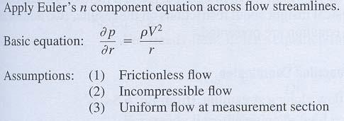
9 For steady flow in a horizontal plane: Equation 6.6b indicates that pressure increases in the direction outward from the center of curvature of the streamlines. In regions where the streamlines are straight, the radius of curvature, R, is infinite and there is no pressure variation normal to the streamlines. Ex. 6.1 Flow in a bend: Compute the approximate flow rate.
10
11 6.3 Bernoulli Equation Integration of Euler s Equation along a streamline for Steady Flow Derivation Using Streamline Coordinates
12
13 The Bernoulli equation is powerful and useful equation because it relates pressure changes to velocity and elevation changes along a streamline. However, it gives correct results only when applied to a flow situation whenever all four of the restrictions are reasonable. In general, the Bernoulli constant in Eq. 6.9 has different values along different streamlines. For the case of irrotational flow, the constant has a single value throughout the entire flow field Derivation Using Rectangular Coordinates
14
15
16 As expected, we see that the last two equations are identical to Eqs. 6.8 and 6.9 derived previously using streamline coordinates.
17 The Bernoulli equation, derived using rectangular coordinates, is still subject to the restrictions: (1) steady flow, (2) incompressible flow, (3) frictionless flow, and (4) flow along a streamline Static, Stagnation, and Dynamic Pressures The pressure, p, which we have used in deriving the Bernoulli equation, E. 6.9, is the thermodynamic pressure; is commonly called the static pressure. The static pressure is that pressure which would be measured by an instrument moving with the flow. However, such a measurement is rather difficult to make in a practical situation! How do we measure static pressure experimentally? In Section 6-2 we showed that there was no pressure variation
18 normal to straight streamlines. This fact makes it possible to measure the static pressure in a flowing fluid using a wall pressure tap, placed in a region where the flow streamlines are straight, as shown in Fig. 6.2a. The pressure tap is a small hole, drilled carefully in the wall,
19 with its axis perpendicular to the surface. If the hole is perpendicular to the duct wall and free from burrs, accurate measurements of static pressure can be made by connecting the tap to a suitable pressure-measuring instrument. In a fluid stream far from a wall, or where streamlines are curved, accurate static pressure measurements can be made by careful use of a static pressure probe, shown in Fig. 6.2b. Such probes must be designed so that the measuring holes are placed correctly with respect to the probe tip and stem to avoid erroneous results. In use, the measuring section must be aligned with the local flow direction. Static pressure probes are available commercially in sizes as small as 1.5 mm (1/16 in.) in diameter. The stagnation pressure is obtained when a flowing fluid is
20 decelerated to zero speed by a frictionless process. In incompressible flow, the Bernoulli equation can be used to related changes in speed and pressure along a streamline for such a process. The term 1/2ρV 2 generally is called the dynamic pressure.
21 Thus, if the stagnation pressure and static pressure could be measured at a point, Eq would give the local flow speed. Stagnation pressure is measured in the laboratory using a probe with a hole that faces directly upstream as shown in Fig Such a probe is called a stagnation pressure probe, or pitot tube.
22 If we knew the stagnation pressure and static pressure at a same point, then the flow speed could be computed form Eq Two possible experimental setups are shown in Fig. 6.4 In Fig. 6.4a, the static pressure corresponding to point A is read from the wall static pressure tap. The stagnation pressure is
23 measured directly at A by the total head tube, as shown. (The stem of the total head tube is placed downstream from the measurement location to minimize disturbance of the local flow.) Two probes often are combined, as in the pitot-static tube
24 shown in Fig. 6.4b. The inner tube is used to measure the stagnation pressure at point B, while the static pressure at C is sensed using the small holes in the outer tube. In flow fields where the static pressure variation in the streamwise direction is small, the pito-static tube may be used to infer the speed at point B in the flow by assuming p B =p C and using Eq Remember tat the Bernoulli equation applies only for incompressible flow (Mach number, M 0.3). Ex. 6.2 Pitot Tube: Find the flow speed.

25 6.3.4 Applications where subscripts 1 and 2 represent any two points on a streamline.

26 Ex. 6.3 Nozzle Flow: Find p 1 -p atm.
 Speed of water leaving as a free jet, (b) Pressure at")
27 Ex. 6.4 Flow through a Siphon: Find (a) Speed of water leaving as a free jet, (b) Pressure at point A in the flow. Ex. 6.5 Flow under a Sluice Gate: Find (a) V2, (b) Q/w (ft 3 /s per


28 foot of width) Ex. 6.6 Bernoulli Equation in Translating Reference Frame: Find, p B p 0 A
29

30 6.3.5 Cautions on Use of the Bernoulli Equation Flow through nozzle was modeled well by the Bernoulli equation. Because the pressure gradient in a nozzle is favorable, there is no separation and boundary layers on the walls remain thin. Friction has a negligible effect on the low velocity profile, so 1-D flow is a good model. A diverging passage or sudden expansion should not be
31 modeled using the Bernoulli equation. Adverse pressure gradients cause rapid growth of boundary layers, severely distorted velocity profiles, and possible flow separation. 1-D flow is a poor model for such flows. The hydraulic jump is an example of an open-channel flow with adverse pressure gradient. Flow through a hydraulic jump is mixed violently, making it impossible to identify streamlines. Thus the Bernoulli equation cannot be used to model flow through a hydraulic jump. The Bernoulli equation cannot be applied through a machine such as propeller, pump, or windmill. It is impossible to have locally steady flow or to identify streamlines during flow through a machine. Temperature changes can cause significant changes in density
32 of a gas, even for low-speed flow. Thus the Bernoulli equation could not be applied to air flow through a heating element (e.g., of a hand-held hair dryer) where temperature changes are significant. 6.4 Relation Between The 1 st Law of Thermodynamics and the Bernoulli Equation The Bernoulli equation, Eq. 6.9, was obtained by integrating Euler s equation along a streamline for steady, incompressible, frictionless flow. Thus Eq. 6.9 was derived from the momentum equation for a fluid particle. An equation identical in form to Eq. 6.9 (although requiring very different restrictions) may be obtained from the 1 st law of thermodynamics.
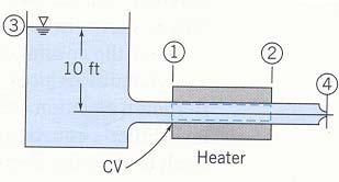
33 Consider steady flow in the absence of shear forces. We choose a control volume bounded by streamlines along is periphery. Such a boundary, shown in Fig. 6.5, often is called a stream tube.
34
35
36
37 Equation 6.16 is identical in form to the Bernoulli equation, Eq The Bernoulli equation was derived from momentum
38 considerations (Newton s 2 nd law), and is valid for steady, incompressible, frictionless flow along a streamline. Equation 6.16 was obtained by applying the 1 st law of thermodynamics to a stream tube control volume, subject to restrictions 1 through 7 above. Thus the Bernoulli equation (Eq. 6.9) and the identical form of the energy equation (Eq. 6.16) were developed from entirely different models, coming from entirely different basic concepts, and involving different restrictions. Note that the restriction 7 (u 2 -u 1 -δq/dm=0) was necessary to obtain the Bernoulli equation form the 1 st law of thermodynamics. This restriction can be satisfied if δq/dm is zero (there is no heat transfer to the fluid) and u 2 =u 1 (there is no change in the
39 internal thermal energy of the fluid). The restriction also is satisfied if (u 2- u 1 ) and δq/dm are nonzero provided that the two terms are equal (this is true for incompressible frictionless flow). For the special case considered in this section it is true that the 1 st law of thermodynamics reduces to the Bernoulli equation. The Bernoulli equation was obtained by integrating the differential form of Newton s 2 nd law (Euler s equation) for steady, incompressible, frictionless flow along a streamline. Each term in the Bernoulli equation has dimensions of energy per unit mass. The Bernoulli equation may be viewed as a mechanical energy balance. In those cases wherein there is no conversion of mechanical to thermal energy, mechanical energy and thermal
40 energy are separately conserved. For these cases, the 1 st law of thermodynamics and Newton s 2 nd law do not yield separate information. However, in general, the 1 st law of thermodynamics and Newton s 2 nd law are independent equations that must be satisfied separately. Ex. 6.7 Internal energy and heat transfer in frictionless incompressible flow: u 2 -u 1 =δq/dm Ex. 6.8 frictionless flow with heat transfer:
41

42 For steady, frictionless, incompressible flow along a streamline, we have shown that the 1 st law of thermodynamics reduces to the Bernoulli equation. From Eq we conclude that there is no loss of mechanical energy in such a flow. Often it is convenient to represent the mechanical energy level
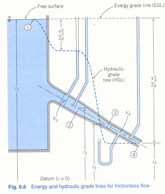
43 of a flow graphically. The energy grade line (EGL) represents the total head height. Liquid would rise to the EGL height in a total head tube placed in the flow. The hydraulic grade line (HGL) height represents the sum of
44 the elevation and static pressure heads, z+p/ρg. In a static pressure tap attached to the flow conduit, liquid would rise to the HGL height. The difference in heights between the EGL and the HGL represents the dynamic (velocity) head, V 2 /2g.
45
46 : the free surface in the large reservoir. There the velocity is negligible and the pressure is atmospheric. : The velocity head increases from zero to V 2 2 /2g as the liquid accelerates into the first section of constant-diameter tube. : The velocity increase again in the reducer between and. : The velocity become constant between and. : At the free discharge at section, the static head is zero. 6.5 Unsteady Bernoulli Equation- Integration of Euler s Equation Along a Streamline The momentum equation for frictionless flow was found to be
47 1 DV p gk ρ = Dt (6.3) It can be converted to a scalar equation by taking the dot product with ds, where ds is an element of distance along a streamline. Thus
48

49 To evaluate the integral term in Eq. 6.21, the variation in V / t must be known as a function of s, the distance along the streamline measured from point 1. Ex. 6.9 Unsteady Bernoulli Equaiton
50
51 6.6 Irrotational Flow An irrotational flow is one in which fluid elements moving in the flow field do not undergo any rotation. For ω = 0, V = 0
52 In cylindrical coordinates Bernoulli Equation Applied to Irrotational Flow If, in addition to being inviscid, steady, and incompressible, the flow field is also irrotational, we can show that Bernoulli s equation can be applied between any two points in the flow To illustrate this, we start with Euler s equation in vector form,
53
54 Since dr was an arbitrary displacement, Eq is valid between any two points in a steady, incompressible, inviscid flow
55 that is also irrotational Velocity Potential In Section 5.2 we formulated the stream function, ψ, which relates the streamlines and mass flow rate in 2-D, incompressible flow. We can formulate a relation called the potential function, φ, for a velocity field tat is irrotational. To do so, we must use the fundamental vector identity which is valid if is a scalar function having continuous first and second derivatives. Then, for an irrotational flow in which V = 0, a scalar
56 function, φ, must exist such that the gradient of φ is proportional to the velocity vector, V. In order that the positive direction of flow be in the direction of decreasing φ, we define φ so that In cylindrical coordinates
57 The velocity potential, φ, exist only for irrotational flow. The stream function, ψ, satisfies the continuity equation for incompressible flow; the stream function is not subject to the restriction of irrotational flow. Irrotationality may be a valid assumption for those regions of a flow in which viscous forces are negligible, i.e. a region exists outside the boundary layer in the flow over a solid surface. The theory for irrotational flow is developed in terms of an imaginary ideal fluid whose viscosity is identically zero. Since,
58 in an irrotational flow, the velocity field may be defined by the potential function, φ, the theory is often referred to as potential flow theory. All real fluids possess viscosity, but there are many situations in which the assumption of inviscid flow considerably simplifies the analysis and, at the same time, gives meaningful results ψ and φ for 2-D, Irrotational, Incompressible Flow: Laplace Equation
59
60 Equation 6.30 and 6.31 are forms of Laplace s equation- an equation that arises in many areas of the physical sciences and engineering. Any function φ and ψ that satisfies Laplace s equation represent a possible 2-D, incompressible, irrotational flow field.
61 Comparing Eqs and 6.33, we see that the slope of a
62 constant ψ line at any point is the negative reciprocal of the slope of the constant φ line at that point; lines of constant ψ and constant φ are orthogonal. This property of potential lines and streamlines is useful in graphical analyses of flow fields. Ex Velocity potential, ψ =ax 2 -ay 2, where a=3 s -1. Show that the flow is irrotational. Find: φ Elementary Plane Flows A variety of potential flows can be constructed by superposing elementary flow patterns. The φ and ψ functions for five elementary 2-D flows- a uniform flow( 均勻流 ), a source( 源 ), a sink( 沈 ), a vortex( 渦流 ),
63 and a doublet( 偶流 ). Uniform flow: inclined at angle α to the x axis, ψ=(u cosα)y-(u sinα)x, φ=-(u sinα)y-(u cosα)x Source: flow is radially outward from the z axis and symmetrical in all directions. Sink: flow is radially inward; a sink is a negative source. Sources and sinks have no exact physical counterparts. The primary value of the concept of sources and sinks is that, when combined with other elementary flows, they produce flow patterns that adequately represent realistic flows.
64
65 Vortex: the velocity distribution in an irrotational vortex can 2 1 dp Vθ be determined from Euler s equation ( = ) and the ρ dr r Bernoulli equation ( dp = VdV θ θ ). ρ 2 Vθ dr = V θ dv θ Vdr θ + rdvθ = 0 rv θ = constant r Doublet: this flow is produced mathematically by allowing a source and a sink of numerically equal strengths to merge.
66
67 6.6.5 Superposition of Elementary Plane Flows Both φ and ψ satisfy Laplace s equation for flow that is both incompressible and irrotational. Since Laplace s equation is a linear, homogeneous PDE, solution may be superposed to develop more complex and interesting patterns of flow. The object of superposition of elementary flow is to produce flow patterns similar to those of practical interest. Since there is no flow across a streamline, any streamline contour can be imagined to represent a solid surface. Through the end of the nineteenth century, workers in pure hydrodynamics failed to produce results that agreed with experiment. Potential flows produced body shapes with lift but predicted zero drag (the d Alembert paradox ). Two influences changed this situation: first Prandtl introduced
68 the BL concept and began to develop the theory, and the second, interest in aeronautics increased dramatically int the early 1900s. Prandtl showed by mathematical analysis and through elegantly simple experiments that viscous effects are confined to a thin boundary layer on the surface of a body. Even for real fluids, flow outside the BL behaves as though the fluid had zero viscosity. Pressure gradients from the external flow are impressed on the BL. The most important input to a calculation of the real fluid flow in the BL is the pressure distribution. Once the velocity field is known from the potential flow solution, the pressure distribution may be calculated. Two methods of combining elementary flows may be used. The direct method consists of combining elementary flows.
69 Distributed line sources, sinks, and images may be used to create bodies of arbitrary shape. (mathematical techniques: complex variables and conformal transformations, can be used to obtain flow fields for interesting geometries) The inverse methods of superposition calculates the body shape to produce a desired pressure distribution. (a large computer code must be used.)
70
71
72
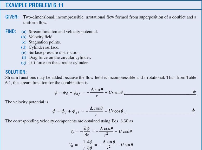
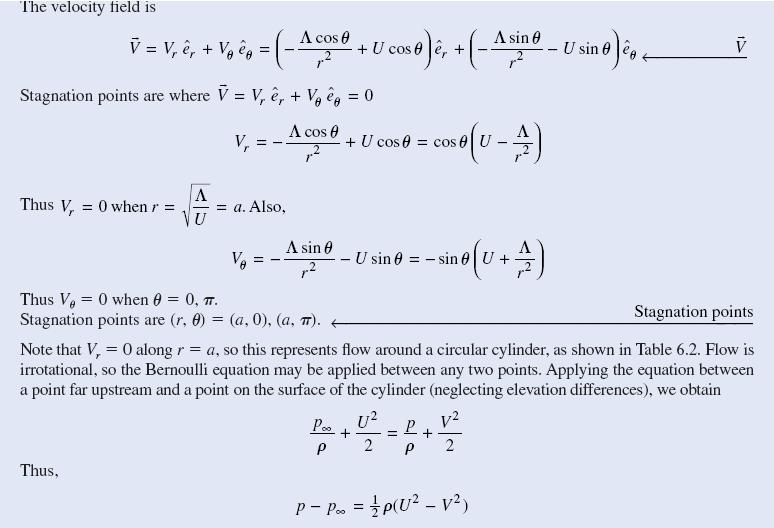
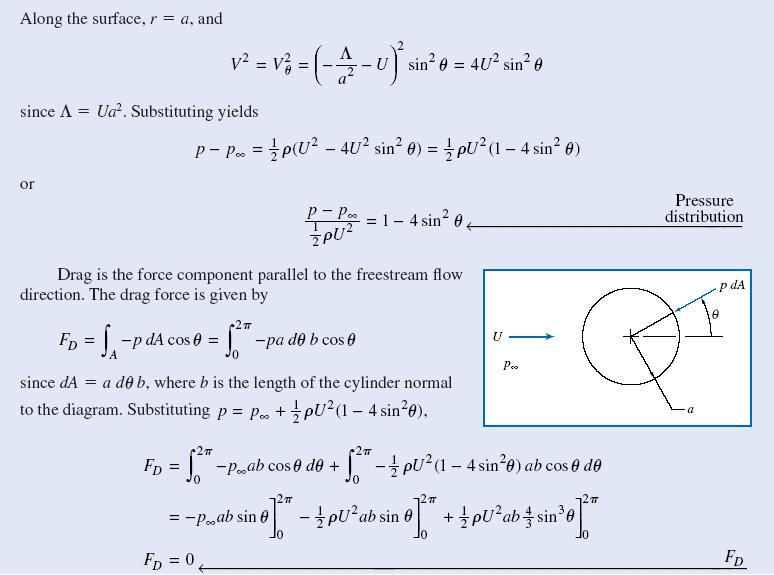
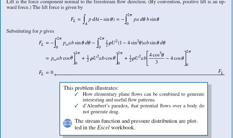
73 Ex Flow over a cylinder: superposition of doublet and uniform flow.
74
75
76
77
78

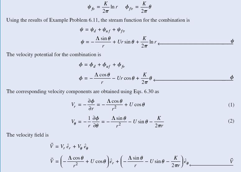
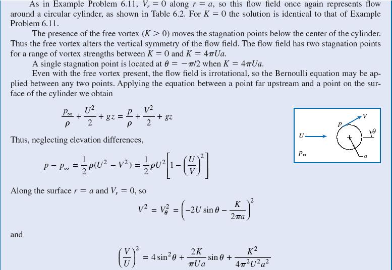
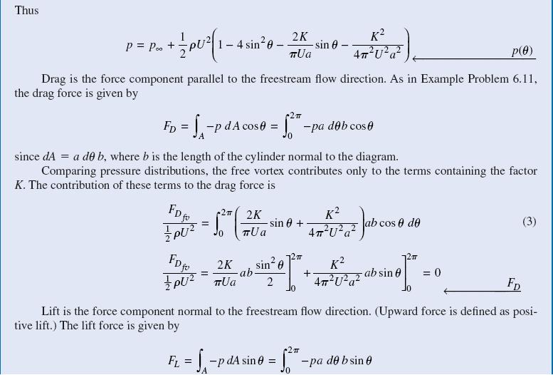
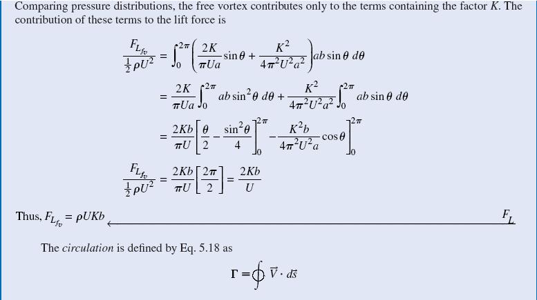
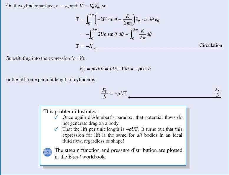
79 Ex Flow over a cylinder: superposition of doublet, uniform flow, and clockwise free vortex.
80
81

82
83
84
85
86
Chapter 3 Bernoulli Equation
 1 Bernoulli Equation 3.1 Flow Patterns: Streamlines, Pathlines, Streaklines 1) A streamline, is a line that is everywhere tangent to the velocity vector at a given instant. Examples of streamlines around
V (r,t) = i ˆ u( x, y,z,t) + ˆ j v( x, y,z,t) + k ˆ w( x, y, z,t)
 = i ˆ u( x, y,z,t) + ˆ j v( x, y,z,t) + k ˆ w( x, y, z,t)") IV. DIFFERENTIAL RELATIONS FOR A FLUID PARTICLE This chapter presents the development and application of the basic differential equations of fluid motion. Simplifications in the general equations and common
IV. DIFFERENTIAL RELATIONS FOR A FLUID PARTICLE This chapter presents the development and application of the basic differential equations of fluid motion. Simplifications in the general equations and common
Objectives. Conservation of mass principle: Mass Equation The Bernoulli equation Conservation of energy principle: Energy equation
 Objectives Conservation of mass principle: Mass Equation The Bernoulli equation Conservation of energy principle: Energy equation Conservation of Mass Conservation of Mass Mass, like energy, is a conserved
Some Basic Plane Potential Flows
 Some Basic Plane Potential Flows Uniform Stream in the x Direction A uniform stream V = iu, as in the Fig. (Solid lines are streamlines and dashed lines are potential lines), possesses both a stream function
The Bernoulli Equation
 The Bernoulli Equation The most used and the most abused equation in fluid mechanics. Newton s Second Law: F = ma In general, most real flows are 3-D, unsteady (x, y, z, t; r,θ, z, t; etc) Let consider
Chapter 5. The Differential Forms of the Fundamental Laws
 Chapter 5 The Differential Forms of the Fundamental Laws 1 5.1 Introduction Two primary methods in deriving the differential forms of fundamental laws: Gauss s Theorem: Allows area integrals of the equations
Detailed Outline, M E 320 Fluid Flow, Spring Semester 2015
 Detailed Outline, M E 320 Fluid Flow, Spring Semester 2015 I. Introduction (Chapters 1 and 2) A. What is Fluid Mechanics? 1. What is a fluid? 2. What is mechanics? B. Classification of Fluid Flows 1. Viscous
2.The lines that are tangent to the velocity vectors throughout the flow field are called steady flow lines. True or False A. True B.
 CHAPTER 03 1. Write Newton's second law of motion. YOUR ANSWER: F = ma 2.The lines that are tangent to the velocity vectors throughout the flow field are called steady flow lines. True or False 3.Streamwise
EGN 3353C Fluid Mechanics
 Lecture 8 Bernoulli s Equation: Limitations and Applications Last time, we derived the steady form of Bernoulli s Equation along a streamline p + ρv + ρgz = P t static hydrostatic total pressure q = dynamic
ENGINEERING FLUID MECHANICS. CHAPTER 1 Properties of Fluids
 CHAPTER 1 Properties of Fluids ENGINEERING FLUID MECHANICS 1.1 Introduction 1.2 Development of Fluid Mechanics 1.3 Units of Measurement (SI units) 1.4 Mass, Density, Specific Weight, Specific Volume, Specific
Chapter Four fluid flow mass, energy, Bernoulli and momentum
 4-1Conservation of Mass Principle Consider a control volume of arbitrary shape, as shown in Fig (4-1). Figure (4-1): the differential control volume and differential control volume (Total mass entering
Fundamentals of Fluid Mechanics
 Sixth Edition Fundamentals of Fluid Mechanics International Student Version BRUCE R. MUNSON DONALD F. YOUNG Department of Aerospace Engineering and Engineering Mechanics THEODORE H. OKIISHI Department
CEE 3310 Control Volume Analysis, Oct. 7, D Steady State Head Form of the Energy Equation P. P 2g + z h f + h p h s.
 CEE 3310 Control Volume Analysis, Oct. 7, 2015 81 3.21 Review 1-D Steady State Head Form of the Energy Equation ( ) ( ) 2g + z = 2g + z h f + h p h s out where h f is the friction head loss (which combines
Lesson 6 Review of fundamentals: Fluid flow
 Lesson 6 Review of fundamentals: Fluid flow The specific objective of this lesson is to conduct a brief review of the fundamentals of fluid flow and present: A general equation for conservation of mass
NPTEL Quiz Hydraulics
 Introduction NPTEL Quiz Hydraulics 1. An ideal fluid is a. One which obeys Newton s law of viscosity b. Frictionless and incompressible c. Very viscous d. Frictionless and compressible 2. The unit of kinematic
vector H. If O is the point about which moments are desired, the angular moment about O is given:
 The angular momentum A control volume analysis can be applied to the angular momentum, by letting B equal to angularmomentum vector H. If O is the point about which moments are desired, the angular moment
Chapter 6: Incompressible Inviscid Flow
 Chapter 6: Incompressible Inviscid Flow 6-1 Introduction 6-2 Nondimensionalization of the NSE 6-3 Creeping Flow 6-4 Inviscid Regions of Flow 6-5 Irrotational Flow Approximation 6-6 Elementary Planar Irrotational
MAE 101A. Homework 7 - Solutions 3/12/2018
 MAE 101A Homework 7 - Solutions 3/12/2018 Munson 6.31: The stream function for a two-dimensional, nonviscous, incompressible flow field is given by the expression ψ = 2(x y) where the stream function has
Mass of fluid leaving per unit time
 5 ENERGY EQUATION OF FLUID MOTION 5.1 Eulerian Approach & Control Volume In order to develop the equations that describe a flow, it is assumed that fluids are subject to certain fundamental laws of physics.
10.52 Mechanics of Fluids Spring 2006 Problem Set 3
 10.52 Mechanics of Fluids Spring 2006 Problem Set 3 Problem 1 Mass transfer studies involving the transport of a solute from a gas to a liquid often involve the use of a laminar jet of liquid. The situation
BERNOULLI EQUATION. The motion of a fluid is usually extremely complex.
 BERNOULLI EQUATION The motion of a fluid is usually extremely complex. The study of a fluid at rest, or in relative equilibrium, was simplified by the absence of shear stress, but when a fluid flows over
Offshore Hydromechanics Module 1
 Offshore Hydromechanics Module 1 Dr. ir. Pepijn de Jong 4. Potential Flows part 2 Introduction Topics of Module 1 Problems of interest Chapter 1 Hydrostatics Chapter 2 Floating stability Chapter 2 Constant
3.25 Pressure form of Bernoulli Equation
 CEE 3310 Control Volume Analysis, Oct 3, 2012 83 3.24 Review The Energy Equation Q Ẇshaft = d dt CV ) (û + v2 2 + gz ρ d + (û + v2 CS 2 + gz + ) ρ( v n) da ρ where Q is the heat energy transfer rate, Ẇ
FLUID MECHANICS. Chapter 9 Flow over Immersed Bodies
 FLUID MECHANICS Chapter 9 Flow over Immersed Bodies CHAP 9. FLOW OVER IMMERSED BODIES CONTENTS 9.1 General External Flow Characteristics 9.3 Drag 9.4 Lift 9.1 General External Flow Characteristics 9.1.1
CEE 3310 Control Volume Analysis, Oct. 10, = dt. sys
 CEE 3310 Control Volume Analysis, Oct. 10, 2018 77 3.16 Review First Law of Thermodynamics ( ) de = dt Q Ẇ sys Sign convention: Work done by the surroundings on the system < 0, example, a pump! Work done
In this section, mathematical description of the motion of fluid elements moving in a flow field is
 Jun. 05, 015 Chapter 6. Differential Analysis of Fluid Flow 6.1 Fluid Element Kinematics In this section, mathematical description of the motion of fluid elements moving in a flow field is given. A small
PEMP ACD2505. M.S. Ramaiah School of Advanced Studies, Bengaluru
 Two-Dimensional Potential Flow Session delivered by: Prof. M. D. Deshpande 1 Session Objectives -- At the end of this session the delegate would have understood PEMP The potential theory and its application
FLUID MECHANICS. Chapter 3 Elementary Fluid Dynamics - The Bernoulli Equation
 FLUID MECHANICS Chapter 3 Elementary Fluid Dynamics - The Bernoulli Equation CHAP 3. ELEMENTARY FLUID DYNAMICS - THE BERNOULLI EQUATION CONTENTS 3. Newton s Second Law 3. F = ma along a Streamline 3.3
General Solution of the Incompressible, Potential Flow Equations
 CHAPTER 3 General Solution of the Incompressible, Potential Flow Equations Developing the basic methodology for obtaining the elementary solutions to potential flow problem. Linear nature of the potential
CHAPTER 3 BASIC EQUATIONS IN FLUID MECHANICS NOOR ALIZA AHMAD
 CHAPTER 3 BASIC EQUATIONS IN FLUID MECHANICS 1 INTRODUCTION Flow often referred as an ideal fluid. We presume that such a fluid has no viscosity. However, this is an idealized situation that does not exist.
Inviscid & Incompressible flow
 < 3.1. Introduction and Road Map > Basic aspects of inviscid, incompressible flow Bernoulli s Equation Laplaces s Equation Some Elementary flows Some simple applications 1.Venturi 2. Low-speed wind tunnel
5 ENERGY EQUATION OF FLUID MOTION
 5 ENERGY EQUATION OF FLUID MOTION 5.1 Introduction In order to develop the equations that describe a flow, it is assumed that fluids are subject to certain fundamental laws of physics. The pertinent laws
CLASS SCHEDULE 2013 FALL
 CLASS SCHEDULE 2013 FALL Class # or Lab # 1 Date Aug 26 2 28 Important Concepts (Section # in Text Reading, Lecture note) Examples/Lab Activities Definition fluid; continuum hypothesis; fluid properties
Iran University of Science & Technology School of Mechanical Engineering Advance Fluid Mechanics
 1. Consider a sphere of radius R immersed in a uniform stream U0, as shown in 3 R Fig.1. The fluid velocity along streamline AB is given by V ui U i x 1. 0 3 Find (a) the position of maximum fluid acceleration
Lifting Airfoils in Incompressible Irrotational Flow. AA210b Lecture 3 January 13, AA210b - Fundamentals of Compressible Flow II 1
 Lifting Airfoils in Incompressible Irrotational Flow AA21b Lecture 3 January 13, 28 AA21b - Fundamentals of Compressible Flow II 1 Governing Equations For an incompressible fluid, the continuity equation
Chapter 7 The Energy Equation
 Chapter 7 The Energy Equation 7.1 Energy, Work, and Power When matter has energy, the matter can be used to do work. A fluid can have several forms of energy. For example a fluid jet has kinetic energy,
Given the water behaves as shown above, which direction will the cylinder rotate?
 water stream fixed but free to rotate Given the water behaves as shown above, which direction will the cylinder rotate? ) Clockwise 2) Counter-clockwise 3) Not enough information F y U 0 U F x V=0 V=0
MASS, MOMENTUM, AND ENERGY EQUATIONS
 MASS, MOMENTUM, AND ENERGY EQUATIONS This chapter deals with four equations commonly used in fluid mechanics: the mass, Bernoulli, Momentum and energy equations. The mass equation is an expression of the
ME3560 Tentative Schedule Spring 2019
 ME3560 Tentative Schedule Spring 2019 Week Number Date Lecture Topics Covered Prior to Lecture Read Section Assignment Prep Problems for Prep Probs. Must be Solved by 1 Monday 1/7/2019 1 Introduction to
INSTITUTE OF AERONAUTICAL ENGINEERING Dundigal, Hyderabad AERONAUTICAL ENGINEERING QUESTION BANK : AERONAUTICAL ENGINEERING.
 Course Name Course Code Class Branch INSTITUTE OF AERONAUTICAL ENGINEERING Dundigal, Hyderabad - 00 0 AERONAUTICAL ENGINEERING : Mechanics of Fluids : A00 : II-I- B. Tech Year : 0 0 Course Coordinator
Chapter 4 DYNAMICS OF FLUID FLOW
 Faculty Of Engineering at Shobra nd Year Civil - 016 Chapter 4 DYNAMICS OF FLUID FLOW 4-1 Types of Energy 4- Euler s Equation 4-3 Bernoulli s Equation 4-4 Total Energy Line (TEL) and Hydraulic Grade Line
ME3560 Tentative Schedule Fall 2018
 ME3560 Tentative Schedule Fall 2018 Week Number 1 Wednesday 8/29/2018 1 Date Lecture Topics Covered Introduction to course, syllabus and class policies. Math Review. Differentiation. Prior to Lecture Read
 UNIT IV BOUNDARY LAYER AND FLOW THROUGH PIPES Definition of boundary layer Thickness and classification Displacement and momentum thickness Development of laminar and turbulent flows in circular pipes
Fluid Mechanics-61341
 An-Najah National University College of Engineering Fluid Mechanics-61341 Chapter [5] Flow of An Incompressible Fluid Dr. Sameer Shadeed 1 Fluid Mechanics-2nd Semester 2010- [5] Flow of An Incompressible
Visualization of flow pattern over or around immersed objects in open channel flow.
 EXPERIMENT SEVEN: FLOW VISUALIZATION AND ANALYSIS I OBJECTIVE OF THE EXPERIMENT: Visualization of flow pattern over or around immersed objects in open channel flow. II THEORY AND EQUATION: Open channel:
Fluid Dynamics Problems M.Sc Mathematics-Second Semester Dr. Dinesh Khattar-K.M.College
 Fluid Dynamics Problems M.Sc Mathematics-Second Semester Dr. Dinesh Khattar-K.M.College 1. (Example, p.74, Chorlton) At the point in an incompressible fluid having spherical polar coordinates,,, the velocity
Basic Fluid Mechanics
 Basic Fluid Mechanics Chapter 5: Application of Bernoulli Equation 4/16/2018 C5: Application of Bernoulli Equation 1 5.1 Introduction In this chapter we will show that the equation of motion of a particle
Detailed Outline, M E 521: Foundations of Fluid Mechanics I
 Detailed Outline, M E 521: Foundations of Fluid Mechanics I I. Introduction and Review A. Notation 1. Vectors 2. Second-order tensors 3. Volume vs. velocity 4. Del operator B. Chapter 1: Review of Basic
V/ t = 0 p/ t = 0 ρ/ t = 0. V/ s = 0 p/ s = 0 ρ/ s = 0
 UNIT III FLOW THROUGH PIPES 1. List the types of fluid flow. Steady and unsteady flow Uniform and non-uniform flow Laminar and Turbulent flow Compressible and incompressible flow Rotational and ir-rotational
Rate of Flow Quantity of fluid passing through any section (area) per unit time
 per unit time") Kinematics of Fluid Flow Kinematics is the science which deals with study of motion of liquids without considering the forces causing the motion. Rate of Flow Quantity of fluid passing through any section
Kinematics of Fluid Flow Kinematics is the science which deals with study of motion of liquids without considering the forces causing the motion. Rate of Flow Quantity of fluid passing through any section
Fluid Dynamics Exercises and questions for the course
 Fluid Dynamics Exercises and questions for the course January 15, 2014 A two dimensional flow field characterised by the following velocity components in polar coordinates is called a free vortex: u r
Angular momentum equation
 Angular momentum equation For angular momentum equation, B =H O the angular momentum vector about point O which moments are desired. Where β is The Reynolds transport equation can be written as follows:
Water is sloshing back and forth between two infinite vertical walls separated by a distance L: h(x,t) Water L
 Water L") ME9a. SOLUTIONS. Nov., 29. Due Nov. 7 PROBLEM 2 Water is sloshing back and forth between two infinite vertical walls separated by a distance L: y Surface Water L h(x,t x Tank The flow is assumed to be
ME9a. SOLUTIONS. Nov., 29. Due Nov. 7 PROBLEM 2 Water is sloshing back and forth between two infinite vertical walls separated by a distance L: y Surface Water L h(x,t x Tank The flow is assumed to be
3.8 The First Law of Thermodynamics and the Energy Equation
 CEE 3310 Control Volume Analysis, Sep 30, 2011 65 Review Conservation of angular momentum 1-D form ( r F )ext = [ˆ ] ( r v)d + ( r v) out ṁ out ( r v) in ṁ in t CV 3.8 The First Law of Thermodynamics and
INTRODUCTION TO FLUID MECHANICS June 27, 2013
 INTRODUCTION TO FLUID MECHANICS June 27, 2013 PROBLEM 3 (1 hour) A perfect liquid of constant density ρ and constant viscosity µ fills the space between two infinite parallel walls separated by a distance
STATIC, STAGNATION, AND DYNAMIC PRESSURES
 STATIC, STAGNATION, AND DYNAMIC PRESSURES Bernolli eqation is g constant In this eqation is called static ressre, becase it is the ressre that wold be measred by an instrment that is static with resect
UNIT I FLUID PROPERTIES AND STATICS
 SIDDHARTH GROUP OF INSTITUTIONS :: PUTTUR Siddharth Nagar, Narayanavanam Road 517583 QUESTION BANK (DESCRIPTIVE) Subject with Code : Fluid Mechanics (16CE106) Year & Sem: II-B.Tech & I-Sem Course & Branch:
Unit C-1: List of Subjects
 Unit C-: List of Subjects The elocity Field The Acceleration Field The Material or Substantial Derivative Steady Flow and Streamlines Fluid Particle in a Flow Field F=ma along a Streamline Bernoulli s
PEMP ACD2505. M.S. Ramaiah School of Advanced Studies, Bengaluru
 Governing Equations of Fluid Flow Session delivered by: M. Sivapragasam 1 Session Objectives -- At the end of this session the delegate would have understood The principle of conservation laws Different
CHAPTER 2 INVISCID FLOW
 CHAPTER 2 INVISCID FLOW Changes due to motion through a field; Newton s second law (f = ma) applied to a fluid: Euler s equation; Euler s equation integrated along a streamline: Bernoulli s equation; Bernoulli
Pressure in stationary and moving fluid Lab- Lab On- On Chip: Lecture 2
 Pressure in stationary and moving fluid Lab-On-Chip: Lecture Lecture plan what is pressure e and how it s distributed in static fluid water pressure in engineering problems buoyancy y and archimedes law;
Chapter 5: Mass, Bernoulli, and Energy Equations
 Chapter 5: Mass, Bernoulli, and Energy Equations Introduction This chapter deals with 3 equations commonly used in fluid mechanics The mass equation is an expression of the conservation of mass principle.
Steady waves in compressible flow
 Chapter Steady waves in compressible flow. Oblique shock waves Figure. shows an oblique shock wave produced when a supersonic flow is deflected by an angle. Figure.: Flow geometry near a plane oblique
SPC Aerodynamics Course Assignment Due Date Monday 28 May 2018 at 11:30
 SPC 307 - Aerodynamics Course Assignment Due Date Monday 28 May 2018 at 11:30 1. The maximum velocity at which an aircraft can cruise occurs when the thrust available with the engines operating with the
COURSE NUMBER: ME 321 Fluid Mechanics I 3 credit hour. Basic Equations in fluid Dynamics
 COURSE NUMBER: ME 321 Fluid Mechanics I 3 credit hour Basic Equations in fluid Dynamics Course teacher Dr. M. Mahbubur Razzaque Professor Department of Mechanical Engineering BUET 1 Description of Fluid
In which of the following scenarios is applying the following form of Bernoulli s equation: steady, inviscid, uniform stream of water. Ma = 0.
 bernoulli_11 In which of the following scenarios is applying the following form of Bernoulli s equation: p V z constant! g + g + = from point 1 to point valid? a. 1 stagnant column of water steady, inviscid,
Pressure in stationary and moving fluid. Lab-On-Chip: Lecture 2
 Pressure in stationary and moving fluid Lab-On-Chip: Lecture Fluid Statics No shearing stress.no relative movement between adjacent fluid particles, i.e. static or moving as a single block Pressure at
Fluid Mechanics c) Orificemeter a) Viscous force, Turbulence force, Compressible force a) Turbulence force c) Integration d) The flow is rotational
 Orificemeter a) Viscous force, Turbulence force, Compressible force a) Turbulence force c) Integration d) The flow is rotational") Fluid Mechanics 1. Which is the cheapest device for measuring flow / discharge rate. a) Venturimeter b) Pitot tube c) Orificemeter d) None of the mentioned 2. Which forces are neglected to obtain Euler
Fluid Mechanics 1. Which is the cheapest device for measuring flow / discharge rate. a) Venturimeter b) Pitot tube c) Orificemeter d) None of the mentioned 2. Which forces are neglected to obtain Euler
Fluid Dynamics: Theory, Computation, and Numerical Simulation Second Edition
 Fluid Dynamics: Theory, Computation, and Numerical Simulation Second Edition C. Pozrikidis m Springer Contents Preface v 1 Introduction to Kinematics 1 1.1 Fluids and solids 1 1.2 Fluid parcels and flow
R09. d water surface. Prove that the depth of pressure is equal to p +.
 Code No:A109210105 R09 SET-1 B.Tech II Year - I Semester Examinations, December 2011 FLUID MECHANICS (CIVIL ENGINEERING) Time: 3 hours Max. Marks: 75 Answer any five questions All questions carry equal
CHAPTER 7 SEVERAL FORMS OF THE EQUATIONS OF MOTION
 CHAPTER 7 SEVERAL FORMS OF THE EQUATIONS OF MOTION 7.1 THE NAVIER-STOKES EQUATIONS Under the assumption of a Newtonian stress-rate-of-strain constitutive equation and a linear, thermally conductive medium,
LECTURE NOTES - III. Prof. Dr. Atıl BULU
 LECTURE NOTES - III «FLUID MECHANICS» Istanbul Technical University College of Civil Engineering Civil Engineering Department Hydraulics Division CHAPTER KINEMATICS OF FLUIDS.. FLUID IN MOTION Fluid motion
Fluid Mechanics. du dy
 FLUID MECHANICS Technical English - I 1 th week Fluid Mechanics FLUID STATICS FLUID DYNAMICS Fluid Statics or Hydrostatics is the study of fluids at rest. The main equation required for this is Newton's
Part A: 1 pts each, 10 pts total, no partial credit.
 Part A: 1 pts each, 10 pts total, no partial credit. 1) (Correct: 1 pt/ Wrong: -3 pts). The sum of static, dynamic, and hydrostatic pressures is constant when flow is steady, irrotational, incompressible,
F11AE1 1. C = ρν r r. r u z r
 F11AE1 1 Question 1 20 Marks) Consider an infinite horizontal pipe with circular cross-section of radius a, whose centre line is aligned along the z-axis; see Figure 1. Assume no-slip boundary conditions
For example an empty bucket weighs 2.0kg. After 7 seconds of collecting water the bucket weighs 8.0kg, then:
 Hydraulic Coefficient & Flow Measurements ELEMENTARY HYDRAULICS National Certificate in Technology (Civil Engineering) Chapter 3 1. Mass flow rate If we want to measure the rate at which water is flowing
If a stream of uniform velocity flows into a blunt body, the stream lines take a pattern similar to this: Streamlines around a blunt body
 Venturimeter & Orificemeter ELEMENTARY HYDRAULICS National Certificate in Technology (Civil Engineering) Chapter 5 Applications of the Bernoulli Equation The Bernoulli equation can be applied to a great
1. Introduction - Tutorials
 1. Introduction - Tutorials 1.1 Physical properties of fluids Give the following fluid and physical properties(at 20 Celsius and standard pressure) with a 4-digit accuracy. Air density : Water density
Introduction to Aerospace Engineering
 4. Basic Fluid (Aero) Dynamics Introduction to Aerospace Engineering Here, we will try and look at a few basic ideas from the complicated field of fluid dynamics. The general area includes studies of incompressible,
3.5 Vorticity Equation
 .0 - Marine Hydrodynamics, Spring 005 Lecture 9.0 - Marine Hydrodynamics Lecture 9 Lecture 9 is structured as follows: In paragraph 3.5 we return to the full Navier-Stokes equations (unsteady, viscous
Control Volume. Dynamics and Kinematics. Basic Conservation Laws. Lecture 1: Introduction and Review 1/24/2017
 Lecture 1: Introduction and Review Dynamics and Kinematics Kinematics: The term kinematics means motion. Kinematics is the study of motion without regard for the cause. Dynamics: On the other hand, dynamics
Lecture 1: Introduction and Review
 Lecture 1: Introduction and Review Review of fundamental mathematical tools Fundamental and apparent forces Dynamics and Kinematics Kinematics: The term kinematics means motion. Kinematics is the study
Aerodynamics. Basic Aerodynamics. Continuity equation (mass conserved) Some thermodynamics. Energy equation (energy conserved)
 Some thermodynamics. Energy equation (energy conserved)") Flow with no friction (inviscid) Aerodynamics Basic Aerodynamics Continuity equation (mass conserved) Flow with friction (viscous) Momentum equation (F = ma) 1. Euler s equation 2. Bernoulli s equation
Flow with no friction (inviscid) Aerodynamics Basic Aerodynamics Continuity equation (mass conserved) Flow with friction (viscous) Momentum equation (F = ma) 1. Euler s equation 2. Bernoulli s equation
Figure 3: Problem 7. (a) 0.9 m (b) 1.8 m (c) 2.7 m (d) 3.6 m
 0.9 m (b) 1.8 m (c) 2.7 m (d) 3.6 m") 1. For the manometer shown in figure 1, if the absolute pressure at point A is 1.013 10 5 Pa, the absolute pressure at point B is (ρ water =10 3 kg/m 3, ρ Hg =13.56 10 3 kg/m 3, ρ oil = 800kg/m 3 ): (a)
1. For the manometer shown in figure 1, if the absolute pressure at point A is 1.013 10 5 Pa, the absolute pressure at point B is (ρ water =10 3 kg/m 3, ρ Hg =13.56 10 3 kg/m 3, ρ oil = 800kg/m 3 ): (a)
 CE 6303 MECHANICS OF FLUIDS L T P C QUESTION BANK 3 0 0 3 UNIT I FLUID PROPERTIES AND FLUID STATICS PART - A 1. Define fluid and fluid mechanics. 2. Define real and ideal fluids. 3. Define mass density
PART 1B EXPERIMENTAL ENGINEERING. SUBJECT: FLUID MECHANICS & HEAT TRANSFER LOCATION: HYDRAULICS LAB (Gnd Floor Inglis Bldg) BOUNDARY LAYERS AND DRAG
 BOUNDARY LAYERS AND DRAG") 1 PART 1B EXPERIMENTAL ENGINEERING SUBJECT: FLUID MECHANICS & HEAT TRANSFER LOCATION: HYDRAULICS LAB (Gnd Floor Inglis Bldg) EXPERIMENT T3 (LONG) BOUNDARY LAYERS AND DRAG OBJECTIVES a) To measure the velocity
1 PART 1B EXPERIMENTAL ENGINEERING SUBJECT: FLUID MECHANICS & HEAT TRANSFER LOCATION: HYDRAULICS LAB (Gnd Floor Inglis Bldg) EXPERIMENT T3 (LONG) BOUNDARY LAYERS AND DRAG OBJECTIVES a) To measure the velocity
VARIED FLOW IN OPEN CHANNELS
 Chapter 15 Open Channels vs. Closed Conduits VARIED FLOW IN OPEN CHANNELS Fluid Mechanics, Spring Term 2011 In a closed conduit there can be a pressure gradient that drives the flow. An open channel has
FE Fluids Review March 23, 2012 Steve Burian (Civil & Environmental Engineering)
") Topic: Fluid Properties 1. If 6 m 3 of oil weighs 47 kn, calculate its specific weight, density, and specific gravity. 2. 10.0 L of an incompressible liquid exert a force of 20 N at the earth s surface.
Topic: Fluid Properties 1. If 6 m 3 of oil weighs 47 kn, calculate its specific weight, density, and specific gravity. 2. 10.0 L of an incompressible liquid exert a force of 20 N at the earth s surface.
Flow Measurement in Pipes and Ducts COURSE CONTENT
 Flow Measurement in Pipes and Ducts Dr. Harlan H. Bengtson, P.E. COURSE CONTENT 1. Introduction This course is about measurement of the flow rate of a fluid flowing under pressure in a closed conduit.
Stream Tube. When density do not depend explicitly on time then from continuity equation, we have V 2 V 1. δa 2. δa 1 PH6L24 1
 Stream Tube A region of the moving fluid bounded on the all sides by streamlines is called a tube of flow or stream tube. As streamline does not intersect each other, no fluid enters or leaves across the
1.060 Engineering Mechanics II Spring Problem Set 4
 1.060 Engineering Mechanics II Spring 2006 Due on Monday, March 20th Problem Set 4 Important note: Please start a new sheet of paper for each problem in the problem set. Write the names of the group members
1/3/2011. This course discusses the physical laws that govern atmosphere/ocean motions.
 Lecture 1: Introduction and Review Dynamics and Kinematics Kinematics: The term kinematics means motion. Kinematics is the study of motion without regard for the cause. Dynamics: On the other hand, dynamics
2 Internal Fluid Flow
 Internal Fluid Flow.1 Definitions Fluid Dynamics The study of fluids in motion. Static Pressure The pressure at a given point exerted by the static head of the fluid present directly above that point.
for what specific application did Henri Pitot develop the Pitot tube? what was the name of NACA s (now NASA) first research laboratory?
 first research laboratory?") 1. 5% short answers for what specific application did Henri Pitot develop the Pitot tube? what was the name of NACA s (now NASA) first research laboratory? in what country (per Anderson) was the first
1. 5% short answers for what specific application did Henri Pitot develop the Pitot tube? what was the name of NACA s (now NASA) first research laboratory? in what country (per Anderson) was the first
AE301 Aerodynamics I UNIT B: Theory of Aerodynamics
 AE301 Aerodynamics I UNIT B: Theory of Aerodynamics ROAD MAP... B-1: Mathematics for Aerodynamics B-: Flow Field Representations B-3: Potential Flow Analysis B-4: Applications of Potential Flow Analysis
3. FORMS OF GOVERNING EQUATIONS IN CFD
 3. FORMS OF GOVERNING EQUATIONS IN CFD 3.1. Governing and model equations in CFD Fluid flows are governed by the Navier-Stokes equations (N-S), which simpler, inviscid, form is the Euler equations. For
Vorticity Equation Marine Hydrodynamics Lecture 9. Return to viscous incompressible flow. N-S equation: v. Now: v = v + = 0 incompressible
 13.01 Marine Hydrodynamics, Fall 004 Lecture 9 Copyright c 004 MIT - Department of Ocean Engineering, All rights reserved. Vorticity Equation 13.01 - Marine Hydrodynamics Lecture 9 Return to viscous incompressible
Physics 3 Summer 1990 Lab 7 - Hydrodynamics
 Physics 3 Summer 1990 Lab 7 - Hydrodynamics Theory Consider an ideal liquid, one which is incompressible and which has no internal friction, flowing through pipe of varying cross section as shown in figure
Fluid Mechanics Qualifying Examination Sample Exam 2
 Fluid Mechanics Qualifying Examination Sample Exam 2 Allotted Time: 3 Hours The exam is closed book and closed notes. Students are allowed one (double-sided) formula sheet. There are five questions on
REE Internal Fluid Flow Sheet 2 - Solution Fundamentals of Fluid Mechanics
 REE 307 - Internal Fluid Flow Sheet 2 - Solution Fundamentals of Fluid Mechanics 1. Is the following flows physically possible, that is, satisfy the continuity equation? Substitute the expressions for