Optimal Design of Automotive Exhaust Thermoelectric Generator (AETEG)
|
|
|
- Crystal Carroll
- 5 years ago
- Views:
Transcription

1 Western Michigan University ScholarWorks at WMU Master's Theses Graduate College Optimal Design of Automotive Exhaust Thermoelectric Generator (AETEG) Hassan Fagehi Western Michigan University, Follow this and additional works at: Part of the Aerospace Engineering Commons, and the Mechanical Engineering Commons Recommended Citation Fagehi, Hassan, "Optimal Design of Automotive Exhaust Thermoelectric Generator (AETEG)" (2016). Master's Theses This Masters Thesis-Open Access is brought to you for free and open access by the Graduate College at ScholarWorks at WMU. It has been accepted for inclusion in Master's Theses by an authorized administrator of ScholarWorks at WMU. For more information, please contact
2 OPTIMAL DESIGN OF AUTOMOTIVE EXHAUST THERMOELECTRIC GENERATOR (AETEG) by Hassan Fagehi A thesis submitted to the Graduate College in partial fulfillment of the requirements for the degree of Master of Science in Engineering (Mechanical) Mechanical and Aerospace Engineering Western Michigan University December 2016 Thesis Committee: HoSung Lee, Ph.D., Chair Bade Shrestha, Ph.D. Chris Cho, Ph.D.
3 OPTIMAL DESIGN OF AUTOMOTIVE EXHAUST THERMOELECTRIC GENERATOR (AETEG) Hassan Fagehi, M.S.E. Western Michigan University, 2016 A consumption of energy continues to increase at an exponential rate, especially in terms of automotive spark ignitions vehicles. About 40% of the applied fuel into a vehicle is lost as waste exhaust to the environment. The desire for improved fuel efficiency by recovering the exhaust waste heat in automobiles has become an important subject. The thermoelectric generator (TEG) has the potential to convert exhaust waste heat into electricity as long as it is improving fuel economy. The remarkable amount of research being conducted on TEGs indicates that this technology will have a bright future in terms of power generation. The current study discusses the optimal design of the automotive exhaust thermoelectric generator (AETEG). The work investigates the effect of leg length and ceramic plate materials on the performance of the thermoelectric module. A new design is conducted analytically based on the idea of leg length and the ceramic plate materials effect, giving a significant improvement in terms of power density. Experimental work is conducted to verify the model that used the ideal (standard) equations along with effective material properties. The model is reasonably verified by experimental work, which is mainly due to the utilization of the effective material properties. Hence, the thermoelectric module that was used in the experiment is optimized by using a newly developed optimal design theory (dimensionless analysis technique).
4 2016 Hassan Fagehi
5 ACKNOWLEDGEMENTS Foremost, I would like to especially thank my advisor Prof. HoSung Lee for his encouragement and patience throughout my work. Without his support and guidance this work would not have been possible. I m very lucky and thankful to have Dr. Lee as my advisor, who is always trying to improve his student s knowledge. I would also like to extend my thanks to my committee members, Prof. Bade Shrestha and Prof. Chris Cho, for their guidance and suggestions to improve the quality of this work. I wish to thank the government of Saudi Arabia who believed in me and provided me with a generous scholarship. I would also like to thank my family, especially my mother, my wife, and my daughter for their support and patience. Their support is a big part of my accomplishment. Also, I thank all my friends and classmates for their support and helpful comments. Hassan Fagehi ii
6 TABLE OF CONTENTS ACKNOWLEDGEMENTS... ii LIST OF TABLES... vii LIST OF FIGURES... viii NOMENCLATURE... xii 1 BACKGROUND OF THERMOELECTRIC Thermoelectric Effects Seebeck Effect Peltier Effect Thomson Effect The Figure of Merit Thermoelectric Ideal (Standard) Equations General Governing Equations Thermoelectric Couple Equations Thermoelectric Generators Equations Contact Resistance for Thermoelectric Generator Thermoelectric Generator System Basic Equations of Thermoelectric Generator System iii
7 Table of Contents Continued Heat Sink Design and Optimization Power Density Chapter Conclusion LITERATURE SURVEY AND OBJECTIVES OF THE CURRENT STUDY Background Hot Side Heat Exchanger Coolant System Bypass System Literature Survey of Automotive Exhaust Thermoelectric Generator (AETEG) AETEG System Numerical And Experimental Work of AETEG Motivation Objectives of Current Study MODELING OF (AETEG) Modeling of Module Tests Calculating the Effective Material Properties Dimensional Analysis Method iv
8 Table of Contents Continued 3.4 Heat Sink Optimization Offset Strip-Fin Heat Exchanger (OSF) Exhaust Mass Flow Rate Calculations Pressure Drop Calculations Chapter Conclusion EXPERIMENTAL WORK RESULTS AND DISCUSSION GM Project Module Test Validation AETEG Test Validation Optimizing and Improving GM System (New Design) Applying the New Design of AETEG System for 400 Kw Engine Choosing of 400 Kw Diesel Engine Exhaust Mass Flow Rate Calculation Estimation of Power Output for 400 Kw Engine Experimental Results Effective Material Properties Results Experimental Results Comparing with Analytical Model v
9 Table of Contents Continued Optimizing and Improving Experimental Work CONCLUSION AND FUTURE WORK Conclusion Future Work References APPENDICES A. Derivation of Dimenssionless Equations B. Performance Curves of TE Module vi
10 LIST OF TABLES 2.1: Summary of Previous Efforts on AETEG : Experirement Equipment : Material Properties and Dimensions of the Module Based on [36, 39] : General Motors' Basline Model Configuration Based on [39] : The Configuration Dimensions for OSF Heat Exchanger : The Configuration Dimensions for Plate Fin Heat Exchanger (Cold Side) : Comparison Between Gm System and New System : Engine Specification [51] : Comparison of The Properties and Dimensions for The Commercial Products of T Thermoelectric Module : Experimental Inputs Parameters : Comparison Between the Experimental Using Commercial and the Optimum D Design A long with Improvement Percentage vii
11 LIST OF FIGURES 1.1: Seebeck Effect and the Movement of (A) Electrons and (B) Holes : Peltier and Thomson Effect : Dimensionless Figure of Merits for A Various Nanocomposite Thermoelectric MateMaterials [6] : (A) Longitudinal Cross-Section of A Thermoelectric Couple, (B) (B) Differential Element : A Unit Couple Of Thermoelectric Generator Attached To A Load Resistance : The Energy Balance For Thermoelectric Generator : Normalized Chart For Thermoelectric Generators With Tcth = 0.7 And Zt = : Cutaway Of A Typical Thermoelectric Module [5] : Basic Configuration Of One Couple Including Thermal And Electrical ContContact Resistances : Experimental (Symbols) And Theoretical (Solid Lines) Power Output Of T Of Thermoelectric Generators As A Function Of Temperature DifferDifference Along With Variation Of Leg Length [6] : Thermoelectric Generator Module Attached To Two Heat Sinks : Multiple Array Heat Sink [5] : Typical Energy Flow Path In Internal Combustion Engine : Schematic Of Thermoelectric Generator System : Schematic Of Bypass Flow System : Estimated U.S Energy Consumption In 2015 [44] viii
12 List of Figures Continued 3.1: Te Unicouple Including Thermal And Electrical Contact Resistances : Thermoelectric Generator Module (Teg) With Two Heat Sinks : Offset Strip-Fin Heat Exchanger : (A) Schematic Of Experimental Setup Of One Unit Cell Of Aeteg System, (B) (B) Schematic Of Test Section : (A) Photograph Of Experimental Setup Before Insulation, (B) (B) Photograph Of Experimental Setup After Insulation : Flowchart Of The Experimental Procedure For Four Aeteg Unit : Skutterudite Modules Were Fabricated By Marlow [36] : (A) Power Output Versus Temperature Difference, (B) Voltage VersbVersus Hot Junction Temperature : Maximum Power Output And Efficiency Versus Leg Length With Cera Ceramic Plate Of Two Materials (Aln And Al2o3) : Schematic Of General Motors Teg System : Scamateic Of One Unit Cell : (A) Power Output And Efficiency Versus Load Resistance Ratio. (B) (B) Junction Temperatures Versus Load Resistance Ratio : Calculated Power Output Per Module Along The Module Number In Fl In Flow Direction : (A) Exhaust Inlet Temperature Along The Module Number In Flow Direction, ( (B) Coolant Inlet Temperature Along The Module Number In Flow Direction : Inlet Temperature Difference Along The Module Number In Flow Direction : Total Heat Transfer Rate Versus Fin Thickness For Plate Fin Heat Exchanger : Power Output And Efficiency Versus Load Resistance Ratio For Optimum Plate Plate Fin Heat Exchanger ix
13 List of Figures Continued 5.12: Total Heat Transfer Rate Versus Fin Thickness For Osf Heat Exchanger : Power Output And Efficiency Versus Load Resistance Ratio For Opti Optimum OSF Heat Exchanger : Total Pressure Drop Versus Mass Flow Rate For Osf Heat Exchanger : Total Heat Transfer Rate Versus Fin Thickness For Cold Side : Power Output And Efficiency Versus Load Resistance Ratio For OptimOptimum OSF Heat Exchanger And Optimum Plate Fin (Hot And Cold Sides) : (A) Schematic Of New Design Of Aeteg System, (B) Schematic Of On Of One Unit Cell : Power Output And Efficiency Versus Leg Length : Power Output And Efficiency Versus Load Resistance Ratio For Final Design : Electrical Current And Voltage Versus Load Resistance Ratio For Final Design : Electrical Current Versus Cross Sectional Area Of Te Module : Power Output Versus Mass Flow Rate : Calculated Power Output Per Module Along The Module Number In Flo In Flow Direction For Final Design : (A) Exhaust Inlet Temperature Along The Module Number In Flow Direction, (B) C (B) Coolant Inlet Temperature Along The Module Number In Flow Direction : (A) 400 Kw Engine And Semi-Truck, (B) Engine Performance Curve [51] : Exhaust Mass Flow Rate Versus Engine Speed (Rpm) : Schematic Of Aeteg System For 400 Kw Engine : Comparison Between Calculations With Effective Material Properties And And Commercial Data.. (A) Output Power Versus Hot Side Temperature, (B) (B) Current Versus Hot Side Temperature, (C) Open Circuit Voltage Versus Hot Hot Side Temperature, (D) Voltage Versus Hot Side Temperature x
14 List of Figures Continued 5.29: Comparison Between Experimental And Analytical Junction Temperatures VersuVersus Load Resistance Ratio : Comparison Between Experimental And Analytical Current Versus Load Load Resistance Ratio, (B) Comparison Between Experimental And AnalyAnalytical Voltage Versus Load Resistance Ratio : Comparison Between Experimental And Analytical Power Output And EfficieEfficiency Versus Load Resistance Ratio Using Voltage And Current, (B) C (B) Comparison Between Experimental And Analytical Power Output And E And Efficiency Versus Load Resistance Ratio Using Junction Temperatures : Power Output and Efficiency with and Without Aluminum Blocks VersuVersus Load Resistance Ratio : Power Output And Efficiency Versus Dimensionless (A) Load ResistResistance (B) Conductance (C) Capacitance At Fluid 1 (D) Capacitance At Fl At Fluid 2 (E) Convectance : Power Output and Efficiency Versus (A) Optimum Number of Theof Thermocouples, (B) Optimum Geometry Ratio : Compression Between Commercial Module Used in Experiment and Oand Optimum Design (Te Module) of Power Output and Efficiency : Total Heat Transfer Rate Versus Fin Thickness (Hot Side) : Compression Between Commercial Module Used in Experiment and OptimOptimum Design (Hot Side Heat Exchanger) of Power Output and Efficiency : Total Heat Transfer Rate Versus Fin Thickness (Cold Side) : Compression Between Commercial Module Used in Experiment and OptimOptimum Design (Cold Side Heat Exchanger) of Power Output and Efficiency : Comparison Between Final Optimum Design and Experimental Design xi
15 NOMENCLATURE A c total fin surface area cold side heat sink (mm 2 ) A e cross-sectional area of thermoelement (mm 2 ) A h total fin surface area hot side heat sink (mm 2 ) A M base area of thermoelectric module (mm 2 ) W c p G e Power output (W) specific heat (J/kg.K) thermocouple geometric ratio h heat transfer coefficient of the fluid (W/m 2 K) I L k K L e m h m c n electric current (A) total length of AETEG (mm) thermoelement thermal conductivity (W/m K), k = k p + k n thermal conductance (W/K), K = ka e /L e length of thermoelement (mm) Mass flow rate of hot side (g/s) Mass flow rate of cold side (g/s) the number of thermocouples N m1 dimensionless capacitance at fluid 1 N m2 dimensionless capacitance at fluid 2 N k dimensionless thermal conductance xii
16 Nomenclature Continued N h N I q x Q Q c Q h R Al tal dimensionless convection dimensionless current the rate of heat transfer around the differential element the rate of heat transfer cooling capacity (W) heat rejection (W) thermal resistance of the aluminum block thickness of the aluminum block T 2 cold junction temperature ( C) T 1 hot junction temperature ( C) T 2 cold fluid temperature ( C) T 1 V ċ V ḣ hot fluid temperature ( C) cold fluid volume flow rate (CFM) hot fluid volume flow rate (CFM) W x Z total width of AETEG (mm) direction along the length of the element the figure of merit (1/K) = α 2 /ρk Greek symbols α η Seebeck coefficient (V/K), α = α p α n fin efficiency of the heat sink xiii
17 Nomenclature Continued Subscripts al e c h in n out p Exp. aluminum thermoelement cold hot inlet n-type element outlet n-type element Experimental Comm. Commercial xiv
18 1 BACKGROUND OF THERMOELECTRIC The thermoelectric (TE) is a solid-state device that can directly convert the thermal energy into electrical energy, and vice versa. TE is used for several purposes such as a power generation, and heating and cooling without any intermediary fluids. TE includes two main devices, which are a thermoelectric generator (TEG) and a thermoelectric cooler (TEC). These two devices have no moving parts, which can reduce the mechanical failure and maintenance required. Additionally, they allow for a silent operation when compared to others devices. These advantages make the thermoelectric devices extremely attractive for many applications. TEGs include a significant potential for recovering waste heat using automotive vehicles into power, replacing the alternator [1]. TEG was used also in space exploration in order to convert the heat energy into electricity [2]. Moreover, TEG can be used to convert thermal solar energy into electricity using incoming sunlight [3]. On the other hand, TEC is widely used for heating ventilation and air conditioning purposes of vehicles [4]. In addition, cooling and heating of car seats, refrigeration, and some medical devices are some applications of TEC. 1.1 Thermoelectric Effects Thermoelectric effect is based on three interrelated phenomena, which are the Seebeck effect, the Peltier effect and the Thomson effect. In 1821, a Germany physicist called Thomas Johann Seebeck discovered that by heating one junction of the circuit made of two dissimilar metals, an electromotive force or potential difference can be produced. French physicist Jean Peltier found in 1834 that heating or cooling can be generated by passing a current through the same circuit of dissimilar metals. In 1854, English physicist William Thomson (later called as 1
19 Lord Kelvin) discovered that heat can be either liberated or absorbed by the existence of a temperature difference between two points for an electrical conductor [5] Seebeck Effect The Seebeck effect is the conversion of a temperature difference between two semiconductors into an electrical current. As shown in Figure 1.1 (a) and (b), some free electrons and holes start to move, which then produce a current. Potential difference or voltage is produced between the two junctions due to the temperature difference as expressed by V = α T 1.1 where α is the Seebeck coefficient, T is the temperature difference between the two junction temperature and V is the voltage. (a) 2
20 (b) Figure 1.1: Seebeck effect and the movement of (a) electrons and (b) holes Peltier Effect The Peltier effect is the reverse process of the Seebeck effect, which is a temperature difference generated by passing a current between two different semiconductor materials as illustrated in Figure 1.2. The passing current is proportional to the generated heat with a different sign when the current has opposite direction. The Peltier effect s relation can be expressed by Q peltier = π AB I 1.2 where π AB is the Peltier coefficient, I is the passing current and Q peltier is the heat absorbed or liberated Thomson Effect The Thomson effect deals with a temperature gradient and flowing current through the thermoelectric material, which is schematically shown in Figure 1.2. The Thomson heat is considered to be proportional to both the temperature gradient and electrical current and reversible between heat and electricity. The Thomson heat absorbed or liberated is given by Q Thomson = τ I ΔT 1.3 3
21 where τ is the Thomson effect, I is the current and ΔT is the temperature difference. Figure 1.2: Peltier and Thomson Effect The Figure of Merit The figure of merit Z represents the performance of thermoelectric devices, where the unit is 1/K. The figure of merit is equal to Z = α2 ρk = α2 σ k 1.4 where α is the Seebeck coefficient in (V/K), ρ is the electrical resistivity in (Ωm), k is the thermal conductivity in (W/mK) and σ is the electrical conductivity in (mk/w). It can be seen from Eq. 1.4) that a higher Seebeck coefficient, a higher electrical conductivity, a low electrical resistivity, and a low thermal conductivity are needed in order to have a good value of Z. The dimensionless figure of merit ZT depends on the type of material at a given temperature, where T is the absolute temperature. For the last decades, the value of ZT was limited to be about one with existing devices. Using a new technology such as nano-materials can improve the dimensionless figure of merit, which has been investigated. These investigations show an improvement in the ZT when compared to bulk materials. The main goal is either to increase the power factor (α σ) or decrease the thermal conductivity in order to achieve a higher ZT. One 4

22 of the most widely used materials for a thermoelectric cooler is Bismuth Telluride, which has the highest figure of merit at room temperature. Recently, some research has been done on skutterudite materials, which shows a good performance especially for higher temperature applications such as the thermoelectric generator for automotive exhaust waste heat recovery and solar energy. Figure 1.3 presents the dimensionless figure of merit for various nano-composite thermoelectric materials. It can be seen from the figure that the Bismuth Telluride has the highest ZT at room temperature and the skutterudite at a higher temperature. Figure 1.3: Dimensionless figure of merits for a various nanocomposite thermoelectric materials [6]. 1.2 Thermoelectric Ideal (Standard) Equations General Governing Equations Considering a non-uniformly heated thermoelectric material for isotropic material properties, the continuity equation is given as j =
23 where is the differential operator along with respect to length and j is the current density. The electric field E is affected by j and the temperature gradient T. The coefficients have contributions from both Ohm s law and the Seebeck effect. By differentiating Eq. 1.5 with respect to length, the electric field is equal to E = j ρ + α T 1.6 The heat flow density vector (heat flux) is given by q = α T j k T 1.7 The general heat diffusion equation is expressed as q + q = ρc p T t 1.8 where q is the generated heat by unit volume, ρ is the mass density, c p is the specific heat and T is the rate of change temperature with respect to time. For steady state Eq reduced to q + q = t where q is defined as q = E j = J 2 ρ + j α T 1.10 Following equation can be obtained by substituting Eqns. 1.7and 3.53 in equation 1.9. (k T) + J 2 ρ T dα dt J T =
24 where (k T) is the thermal conduction, J 2 ρ is the Joule heating, and T dα dt is the Thomson coefficient. A study by [7] shows a good agreement between the Thomson coefficient as a function of temperature and the exact solution that neglected the Thomson coefficient. Hence, the Thomson coefficient can be neglected T dα dt = Assumptions of Thermoelectric Ideal (Standard) Equations Below are the important assumptions of thermoelectric ideal (standard) equations: 1) The Thomson effect is negligible. It has been proven analytically and experimentally that the Thomson effect has a very small effect on the performance of TEG and TEC. 2) The electrical and thermal resistances between ceramic plates and thermoelectric elements are negligible. 3) The convection and radiation losses are negligible. 4) The materials properties are assumed to be independent of temperature Thermoelectric Couple Equations Consider two dissimilar semiconductor elements, which are sandwiched between copper conductive tabs, each element is called a thermoelectric leg or pellet, and is either p-type material (positive) or n-type material (negative). These elements are temperature independent with their material properties, which are Seebeck coefficient (α), electrical resistivity (ρ), and thermal conductivity (k), as illustrated in Figure
25 Figure 1.4: Longitudinal Cross-section of a Thermoelectric Couple, (b) differential element. The steady state heat balance at T1 becomes Q 1 = q p + q n 1.12 where q p and q n are the heat flows for p-type and n-type. The heat flows can be defined in terms of the Peltier heat and Fourier s law of conduction as dt q p = α p T 1 I + ( k p A p dx ) x= dt q n = α n T 1 I + ( k n A n dx ) x= By applying the heat balance on the differential element shown in Figure 1.4 (b), the temperature gradient can be obtained as 8
26 q x (q x + dq x dx ) dx + heat transfer across the surface of the element I 2 ρ p dx A p Joul heating = Differentiating Eq with respect to x gives dq p dx = k pa p d dx (dt dx ) 1.16 Inserting Eq into Eq yields d dx ( k pa p dt dx ) + I2 ρ p A p = or, k p A p d dx (dt dx ) = I2 ρ A p 1.18 Integrating Eq gives k p A p d ( dt dx ) = I2 ρ A p dx dt dx = I2 ρ k p A p 2 x + C Using the boundary conditions as T 1 at x = 0 and T 2 at x = L, Eq can be integrated from 0 to L and leads to T 2 dt = I2 L ρ k p A2 x p T 1 0 L + x C 1 (T 2 T 1 ) = I2 ρ 2k p A p 2 L2 + C 1 L p From the above equation, C 1 can be obtained as 9
27 C 1 = I2 ρ 2k p A p 2 L p + ( T 2 T 1 L p ) 1.21 Substituting Eq into Eq at x = 0 gives dt dx = I2 ρ x=0 2k p A2 L p (T 1 T 2 ) 1.22 p L p Substituting Eq into Eq yields q p = α p T 1 I 1 2 I2 ρ pl p A p + k pa p L p (T 1 T 2 ) 1.23 Eq represents the heat transfer for the p-type, by following the similar way the heat transfer equation for n-type can be derived as q n = α n T 1 I 1 2 I2 ρ nl n A n + k na n L n (T 1 T 2 ) 1.24 As shown in Figure 1.1 (a) and Eq. 1.12, the heat transfer rates of thermoelectric couple equal to Q 1 = (α p α n )T 1 I 1 2 I2 ( ρ pl p A p + ρ nl n A n ) ( k pa p L p + k na n L n ) (T 1 T 2 ) and, Q 2 = (α p α n )T 2 I I2 ( ρ pl p A p + ρ nl n A n ) ( k pa p L p + k na n L n ) (T 1 T 2 ) Moreover, the material properties can be added together using the following equations 10
28 α = α p α n 1.27 R = ρ pl p A p + ρ nl n A n 1.28 K = k pa p L p + k na n L n 1.29 where α, R and K are the total Seebeck coefficient: electrical resistance and thermal conductance of the couple, respectively. Simplifying Eqns and 1.26, using Eqns to 3.53 gives Q 1 = αt 1 I 1 2 I2 R + K(T 1 T 2 ) 1.30 Q 2 = αt 2 I I2 R + K(T 1 T 2 ) 1.31 The above two Eqns and 3.53 are known as the ideal (standard) equations. The first term αt 1 I is the Peltier/Seebeck effect, which is a reversible process. A higher Peltier/Seebeck effect is needed in order to have a higher cooling or power generation. The second term 1 2 I2 R is known as the Joule heating, which is an irreversible process. Finally, the third term K(T 1 T 2 ) is the thermal conductance, which is also an irreversible process. The heat flow direction is significant in order to know the type of thermoelectric couple, either a thermoelectric cooler or thermoelectric generator. If the direction of heat flow is same as the direction that shows in Figure 1.4 (a), then it represents the thermoelectric generator. By reversing the heat flow direction, the thermoelectric cooler can be represented. 11
29 1.2.3 Thermoelectric Generators Equations A thermoelectric generator (TEG) is a solid-state device that directly converts the temperature differences or thermal energy into sufficient electricity. As shown in Figure 1.5, due to the connection of two dissimilar materials with the temperature difference, an electrical current can be created. Figure 1.5: A unit couple of thermoelectric generator attached to a load resistance. Using T h for hot side and T c for cold side instead of T 1 and T 2 respectively in Eqns and 3.53, become as Q h = αt h I 1 2 I2 R + K(T h T c ) 1.32 Q c = αt c I I2 R + K(T h T c )
30 Figure 1.6: The energy balance for thermoelectric generator. As illustrated in Figure 1.6 and by applying the first law of thermodynamics, the electrical output can be written as W = Q h Q c 1.34 or, W = αi(t h T c ) I 2 R 1.35 Moreover, the power output can be defined in terms of the load resistance as W = I 2 R L 1.36 As known, Ohm s Law is given as V = IR L = α(t h T c ) IR 1.37 Hence, the circuit s current is equal to I = α(t h T c ) R L + R
31 The thermal efficiency of TEG is defined as the ratio between the power output and the heat input into the system η th = W Q h 1.39 or, I 2 R L η th = αt h I 1 2 I2 R + K(T h T c ) 1.40 The output power and the thermal efficiency can be defined in terms of resistance ratio R L R as η th = W = α 2 T 2 c [( T 1 2 c T ) 1] ( R L h R ) R (1 + R L R ) 2 (1 T c T h ) ( R L R ) (1 R L R ) 1 2 (1 T c T h ) + 1 2ZT (1 R L R ) 2 (1 + T c T h ) where, T is the average temperature and defined as T = T h + T c The maximum parameters for TEG can be divided into two operations, which are maximum conversion energy and maximum power output. First, the maximum conversion 14
32 efficiency which is the maximum possible efficiency can be produced by the system at R L R = 1 + ZT is given as αδt I mc = R( 1 + ZT + 1) 1.44 W mc = α2 ΔT ZT 1 + ZT + 1 η mc = (1 T c T h ) 1 + ZT ZT + T c T h For the maximum power output at R L R are equal to = 1, the current, power output, and efficiency respectively, I mp = αδt 2R 1.47 W max = α2 ΔT 2 4R 1.48 η mp = (1 T c T h ) (1 T c T h ) + 2 ZT (1 + T c T h ) 1.49 For the maximum voltage which can be occurred at the open circuit and given as V max = nαδt
33 Eqns. 1.36, 1.37, 1.38 and 1.40 can be divided by the above equations, which are the maximum parameters respectively in order to get the normalized power output, current, voltage, and efficiency respectively as flows W W max = 4 R L R ( R L R + 1) η η max I = 1 I max R L R + 1 V V max = R L R R L R = R L R [ 1 + ZT + T c T h ] [( R L R + 1) 1 2 (1 T c T h ) + 1 2ZT (R L R + 1) 2 (1 + T c T h )] ( 1 + ZT 1) The average temperature T is important parameter for TEG because of its effect on the performance of the TEG that is related to the hot and cold side temperatures. Eqns to 1.53 are a function only of resistance ratio R L R, while Eq. 3.53) is a function of R L R, T c T h and ZT. Therefore, these normalized parameters can be used to create a generalized graph for the thermoelectric generator as shown in Figure

34 Figure 1.7: Normalized chart for thermoelectric generators with T c T h = 0.7 and ZT = 1. It is evident from the above plot that the maximum power output and the maximum conversion efficiency are close to each other. The maximum power output occurs at R L R = 1, which means the load resistance is equal to the internal resistance. For the maximum conversion efficiency, it exists when the load resistance value is bigger than the internal load resistance value R L R > 1. As shown in Figure 1.8, the TEG module consists of multiple number of thermocouples. The previous analysis was done for one couple (p-type and n-type) and in order to compute the parameters for the module, the parameters must multiply by the total number of thermocouples n as follows (W ) m = nw 1.55 (Q h) m = nq h
35 (Q c) m = nq c 1.57 (R) m = nr 1.58 (R) m = nr 1.59 (R L ) m = nr L 1.60 (V) m = nv 1.61 (K) m = nk 1.62 (I) m = I 1.63 (η th ) m = (W ) m (Q h) m = η th
36 Figure 1.8: Cutaway of a typical thermoelectric module [5]. 1.3 Contact Resistance for Thermoelectric Generator While the above discussion was for ideal equations, the real thermoelectric devices must include thermal and electrical resistances, which are considered in this section. The effect of thermal and electrical resistance can reduce the performance of the thermoelectric generator when compared to the ideal prediction, especially at a small leg length. As shown in Figure 1.9, the thermoelectric thermocouples are connected in a series using a high conducting metal strip and then sandwiched between ceramic plates. In Figure 1.9, ρ c is the electrical contact resistivity, k c is the thermal contact conductivity including the thermal conductivity of the ceramic plates and the thermal contacts, (T 1c and T 2c ) are the junction temperature of elements which are different than junction temperature of the ceramic plate T 1 and T 2. For a single couple the heat balance equations can be written as [5]: 19
37 Figure 1.9: Basic configuration of one couple including thermal and electrical contact resistances. Q 1 = Ak c l c (T 1 T 1c ) 1.65 Q 1 = αit 1c 1 2 I2 R Ak l o (T 2c T 1c ) 1.66 Q 2 = αit 2c I2 R Ak l o (T 2c T 1c ) 1.67 Q 2 = Ak c l c (T 2c T 2 ) 1.68 I = α(t 1c T 2c ) R L + R 1.69 where α = α p + α n and k = k p + k n. Moreover, the electrical resistance includes two resistance: thermocouple and electrical contact. 20
38 R = R o + R c = ρl o A + ρ c A 1.70 Therefore, R = ρl o A (1 + s l o ) 1.71 where = ρ c ρ, Eqns to 1.68 can be rearranged to compute the electrical current as I = Aα(T 1 T 2 ) 2ρl o (1 + s l o ) (1 + 3r l c lo ) 1.72 where r = k k c, Using the above equation with w n = I 2 R, the power output can be expressed as W n = or, the power output per unit area is Aα 2 (T 1 T 2 ) ρl o (1 + s ) (1 + 3r l 2 c) l o lo W ZT (1 + T 1 2 n A = (kt 1 T ) (1 T 2 ) 1 l o 2 T ) 1 4 (1 + s l o ) (1 + 3r l c lo ) The voltage and the conversion efficiency respectively is defined as V n = α(t 1 T 2 ) 2 (1 + 3r l c lo )
39 η cr 1.76 = (1 T 2 T ) 1 2 ZT (1 + T 2 T ) (1 + s ) (1 + 3r l c) + 2 (1 + 3r l c) ξ 1 l o lo lo TEG 1 2 (1 T 2 T ) 1 where, ξ TEG = T 1c T 1 = r l ZT (1 + c lo 1 T 2 T ) (1 T 2 1 (1 + s l o ) (1 + 3r l c lo ) 2 T ) T 1 + r l ZT (1 + 2 c T ) (1 T 2 1 T ) 1 lo (1 + s ) (1 + 3r l c) l o lo r l c lo (1 T 2 T 1 ) (1 + 3r l c lo ) 1.77 This model which includes the contact resistance was verified by [6] along with experimental work that has been done by [8, 9] as shown in Figure 1.10 for three different leg lengths. 22
 and theoretical (solid lines) power output of thermoelectric generators as a function of temperature difference along with variation of leg length [6]. 1.")
40 Figure 1.10: Experimental (symbols) and theoretical (solid lines) power output of thermoelectric generators as a function of temperature difference along with variation of leg length [6]. 1.4 Thermoelectric Generator System The typical TEG system is mostly connected to heat sinks or heat exchangers, which can improve the amount of heat absorption to the thermoelectric generator module. With the connection of heat sinks as shown in Figure 1.11, the ideal equations of thermoelectric along with some new equation are considered. 23
41 1.4.1 Basic Equations of Thermoelectric Generator System Figure 1.11: Thermoelectric generator module attached to two heat sinks. Consider the TEG system as shown in Figure 1.11 operating under the assumption of a steady-state heat transfer. Each heat sink faces a fluid flow that has a temperature T. Subscript 1 and 2 represent the hot and cold quantities respectively. Assuming that the contact resistance in the thermoelectric generator is negligible, the material properties are independent of temperature, the TEG is perfectly insulated, and the p-type and n-type element has the same dimensions. The basic equations for the TEG with two heat sinks are expressed as Q 1 = η 1 h 1 A 1 (T 1 T 1 ) 1.78 Q 1 = n [αit I2 R + A ek L e (T 1 T 2 )]
42 Q 2 = n [αit I2 R + A ek L e (T 1 T 2 )] 1.80 Q 2 = η 2 h 2 A 2 (T 2 T 2 ) 1.81 I = α(t 1 T 2 ) R L + R 1.82 The thermal resistances of the heat sinks can be expressed by the reciprocal of the convection conductance as η 1 h 1 A 1. where, η 1 is the fin efficiency, h 1 is the convection coefficient, and A 1 is the total surface area of the heat sink 1. Moreover, T 1 and T 2 are the thermoelectric junctions temperatures [10] Heat Sink Design and Optimization The main goal of connecting the thermoelectric module to a heat sink is to maximize the amount of heat transfer rate from the fins. At given dimensions, width (W f ), length (L f ) and profile length (b f ) as shown in Figure 1.12, there are some parameters that can be optimized in order to minimize the thermal resistance. These parameters are the fin thickness (t f ), and fin spacing (z f ) of the heat sink. 25
43 Figure 1.12: Multiple array heat sink [5]. as [5] The total fin efficiency is an important parameter for heat sink performance and it is defined η f = tanh mb f mb f 1.83 mb f is defined as mb f = b f ( 2h 1/ ) k f t f where k f is the thermal conductivity and h is the heat transfer coefficient of fluid which can be calculated by using the Nusselt number as h = k fluid Nu L f 1.85 where, k fluid is the thermal conductivity of the fluid. The total heat transfer area of heat sink is given as follow 26
44 A f = n f [2(L f + t f ) + L f z f,opt ] 1.86 where, n f is the number of fins. The optimum fin spacing can be expressed as z f,opt = 3.24L f Re L 1/2 Pr 1/ where, R el and Pr are the Reynolds number and the Prandtl number respectively. Moreover, the fin thickness can be optimized in order to get the maximum heat transfer rate as given q f = η f ha f (T T b ) 1.88 where, T and T b fluid temperature and heat sink base temperature respectively [5] Power Density A power density is a significant factor that can express the performance of a thermoelectric generator system, which can be described as the total amount of power output per module area ( W/cm 2 ). The higher power density is the higher TEG system performance. The power density can also represent the TEG cost ratio, which is especially important for waste heat recovery applications [11]. However, the literature shows that the power density for the TEG system is still very low, which can be a good point to consider and improve in this study. 1.5 Chapter Conclusion In this chapter, the concept of thermoelectric was discussed, which will be helpful to understand the fundamentals of this technology. Some of the important factors were defined, and 27
45 can be used in the current study. In the following chapter, the background of thermoelectric generator for exhaust waste heat recovery and its previous work will be studied and investigated in order to define the objectives and direction of the current study. 28
46 2 LITERATURE SURVEY AND OBJECTIVES OF THE CURRENT STUDY 2.1 Background Internal combustion engines are extensively used in our daily lives, for either gasoline or diesel engines. Two-thirds of the thermal energy of combustion in vehicles is lost as waste heat, whereas 40% is in the form of the exhaust gas is lost [12]. As can be noticed in Figure 2.1, only about 25% of the fuel can be applied for vehicles operation. The thermoelectric generator (TEG) is able to convert this waste heat into electrical power. This electricity can be sent back to an auxiliary battery or a hybrid battery pack [1]. Hence, the alternator can be removed, which increases the efficiency of the vehicle and improves the fuel economy. Figure 2.1: Typical energy flow path in internal combustion engine Hot Side Heat Exchanger As mentioned in Chapter 1, the thermoelectric generator module needs to be attached to a heat exchanger in order to maximize the amount of absorbed heat. The hot gas exhaust is the 29
47 temperature source in the hot side of the TEG module. The exhaust fluid is a mixture of burned and unburned fuel, carbon monoxide, sulfur dioxide and some of the un-used nitrogen. However, the exhaust fluid is considered and modeled as hot air in the current study. Moreover, the design of the heat exchanger is critical, which can enhance the heat transfer rates. The back pressure (pressure drop) is an important parameter that must be considered in this situation. Hence, the optimum design for the heat exchanger including a number of fins, fin thickness, and fin spacing is an effective way to manage these parameters and increases the system performance (refer to Figure 2.2) Coolant System The cold side of thermoelectric generator module can be connected to the coolant system (radiator) of vehicles in order to cool the generator. The size of the coolant heat exchanger can be smaller because of a high heat transfer coefficient of coolant fluid as compared to the air, which can be an advantage for using the coolant system. Furthermore, cooling by air requires an additional pumping power. Hence, as shown in Figure 2.2, the rectangular blocks can be attached to the cold side of thermoelectric generator module while maintaining the coolant fluid at a constant temperature. 30

48 Figure 2.2: Schematic of thermoelectric generator system Bypass System As the vehicle s engine is running, the exhaust gas temperature can exceed a very high temperature that might destroy the thermoelectric generator modules. A bypass system can be located at the entrance of thermoelectric generator system with a control valve, which can control the temperature limitation in order to protect the system as shown in Figure 2.3. Figure 2.3: Schematic of bypass flow system. 31
49 2.2 Literature Survey of Automotive Exhaust Thermoelectric Generator (AETEG) AETEG System As the improvement of thermoelectric materials performance continues, the designing scientists work on applying the available materials into vehicles exhaust waste heat. Both analytical and experimental approaches have been done by using a thermoelectric generator for automotive waste heat recovery. A theoretical study by [13] was concluded that the thermoelectric generator powered by exhaust waste heat could meet the electrical requirement of a medium size vehicle. Yang [14] discussed that the thermoelectric technology has the ability to produce tens of kilowatts by converting the exhaust heat of vehicles. Morelli [15] studied thermoelectric technology for the automotive application needed for developing a new material with a higher figure of merit. Furthermore, the design of an exhaust gas generator such as heat transfer, size, mass, location, backpressure, and cost were investigated. His recommendation was to do more research on skutterudite compounds and a new intermetallic semiconductors. It was also expected that the thermoelectric for a power generator would become viable and competitive for next century. Rogl G. [16] conducted a study that focused on increasing the energy cost and environmental regulation, which expresses the importance of using waste heat in automotive Numerical and Experimental Work of AETEG During World War II, three sizes of thermoelectric generators, which are 6, 15 and 25 watts, were used by the U.S Army Single Corps for heating and charging batteries purposes [17]. One of the earliest studies on the thermoelectric generator for automotive exhaust was constructed in 1963 by [17] with collaboration of U.S. Naval Engineering Experiment Station. The original goal was to produce 500 Watts at 28 Volts with efficiency no less than 3% but their goal could not 32
50 be attained at the contract funding level. However, the maximum power output obtained was W with efficiency about 2.20 % under their operating conditions. Five years later, Embry and Tudor [18] found that the thermoelectric generator applied in exhaust could meet the electrical requirement of a medium size automobile. However, despite recommendations to prove experimentally their analytical finding, the literature does not show that was ever completed. In 1988, Porsche [19] developed a prototype for testing a thermoelectric generator by using the exhaust gas and water circulation system of vehicle. The thermoelectric material that was used is FeSi 2 and was connected to a Porsche engine 944. The results were in a good agreement with the calculations for a temperature difference 490 K between cold and hot sides of thermoelements. The output power was about 58 Watts for 90 thermoelements. In addition, the authors suggested that the use of other materials with a higher dimensionless figure of merit could improve the power output. In 1994, Hi-Z technology [20, 21] conducted testing on the thermoelectric generator using eight diesel truck engines under funding by the US department of energy and California Energy Commission. The thermoelectric generator system used 72 modules that were produced by Hi-Z with bismuth telluride material. The study further discussed the use of Bi 2 Te 3, PbTe, and SiGe in an exhaust heat waste and decided that Bi 2 Te 3 has the best performance regardless of its maximum operating temperature. The goal was to reach 1 Kilowatts of electrical power. As a result, the maximum electrical power output was about 1068 watts at 300 h.p. and 1700 RPM. Nissan Motor [22] developed an advanced type of thermoelectric module based on SiGe material to apply it into exhaust waste heat of a gasoline engine vehicle. The size of the module was 20 mm 2 with height of 9.2 mm with 8 thermocouples. The maximum electric power of the 33
51 module was approximately 1.2 W at the temperature difference between cold and hot sides of about 563 K. A thermoelectric generator system was fabricated of 72 modules with a total volume of mm 3. The measurements were done under the condition of 3000cc gasoline engine with 58 g/s of gas flow rate and 14.2 l/min of cooling water flow rate. The maximum power output was obtained about 35.6 W. The heat exchanger efficiency was 11 % of primary exhaust gas energy flux and the generated power was 0.9 % of the heat flux from exhaust gas to the coolant. Finally, they suggested that the improvement on heat transfer property and thermoelectric material are required to increase the overall performance. In 2002, Matsubara [23] developed a high efficiency thermoelectric generator which was assembled into a gasoline engine. He concluded that the average ZT-values of 1.5 to 2 were needed to attain the goal of 10% overall efficiency. Clarkson University [24] conducted testing on a prototype automobile exhaust thermoelectric generator. The prototype was installed in 1999 GMC Sierra pick-up truck. They concluded that the improvement in fuel efficiency was achieved on the order of 1-2 percent, depending on speed. Some of the numerical models [25, 26, 27] have been done to evaluate the performance of the thermoelectric generator using a plate fin heat exchanger with available commercial Bi 2 Te 3 modules. Espinosa et al. [28] modeled a thermoelectric generator application for a diesel engine, which was composed of Mg 2 Si/Zn 4 Sb 3 and Bi 2 Te 3 for a high and low temperature respectively. The effect of the number of thermoelectric elements and electrical contact were addressed in their work. One TEG module was conducted by [29] to be applied in an automobile. The result showed that the performance could be improved by using the exhaust pipe instead of the radiator. Karri et al. [30] reported the prediction of the performance and fuel savings by using a thermoelectric 34
52 generator placed in the exhaust stream of a sports utility vehicle (SUV) and a stationary, compressed natural gas (CNG)-fueled engine generator set. In 2009 [31], researchers at BMW Company developed the thermoelectric generator prototype based on Bi 2 Te 3 material. The vehicle involved was a BMW 530i. As a result, around 200 W of electrical power were achieved using 24 modules at 130 km/h. Finally, BMW claimed that the future enhancement of thermoelectric generator depended on how well the thermoelectric material could be improved. Kim et al. [32] fabricated a thermoelectric generator using the engine water coolant of passenger vehicles. Their experimental results revealed that the maximum electrical power was approximately 75 W in the driving mode at 80 km/h. The evolution of the TEG cylindrical shape was studied by [33, 34] for a high-power density during phase 3-4 of BSST led US DOE project. A six-cylinder engine of BMW was used at the National Renewable Energy Laboratory (NREL). The bench test was conducted by BSST using the Ford Lincoln and BMW, which has reported electrical power of 125 W. The fuel improvement was predicted to range from 1% to 7%. General Motors (GM) lead a group to design and test a thermoelectric generator for automotive exhaust waste heat. This project was funded by U.S. Department of Energy (DOE) [35]. Some modules based on skutterudite material were fabricated by the Marlow Company in order to sustain with a very high temperature. The module tests were reported by [36] with the maximum output power of 9 W at constant hot and cold junction temperatures of 550 and 80 respectively. The thermoelectric generator consisted of 24 skutterudite modules in the front and 18 bismuth telluride in the rear with a total of 42 modules. GM mentioned that achieving 350 W and 600 W is possible using a Chevrolet Suburban under city and highway driving conditions respectively. The progress of improving their prototype along with developing a high performance 35
53 module was presented by Meisner [37, 38]. Recently, a numerical model was studied by Kumar et al. based on the GM project. Three different configurations of heat exchanger were investigated with the effect of leg geometries. However, the rectangular configuration had the best overall performance [39, 40]. In 2014, X. Liu et al. [41] constructed an energy-harvesting system, which was used in an automobile exhaust pipe using thermoelectric generator. A road test was done on the system using a prototype vehicle called Warrior. The maximum power output was 600 W at an average temperature difference of 182 while the system efficiency was 1.25%. Finally, it was recommended that the optimizing design would be critical to improve the performance of TEG. Zhang et al. [42] were awarded a funded project of $ 11 million dollars by DOE and the US army on automotive waste heat recovery. They developed a nanostructure bulk material to increase module performance. The fabricated module has a high power density of 5.26 W/cm 2 with a 500 temperature difference. A thermoelectric generator system was built using 400 nanostructure modules and tested using an automotive diesel engine. The system generated W of electrical power at an average temperature of 550 and mass flow rate of 480 g/s. In 2016, Kim et al. [43] investigated experimentally thermoelectric generator for waste heat recovery. Forty customized thermoelectric modules were installed on the rectangular heat exchanger, which has a dimension of mm. A six-cylinder diesel engine was used for an engine rotation speed and load of RPM and MPa respectively. The coolant flow rate and temperature were fixed at 8 SLPM and 293 K. The maximum power output was about 119 W 2000 RPM and 0.6 MPa. The conversion efficiency was in the range of
54 2.8%. It was observed that the power output increased with the engine load or speed. The pressure drops were below 1.46 kpa under all experimental condition. Table 2.1: Summary of previous efforts on AETEG Reference Automobile Thermoelectric Technology (TE) Birkholz et al. (1988) [19] Bass et al. (1994) [20, 21] Ikoma et al. (1998) [22] Thacher et al. Porsche engine 944 Class eight Diesel truck (Cummins NTC 350 engine) Nissan Motors (3000cc gasoline engine) 1999 GMC Sierra 90 Thermoelements (FeSi 2 ) 72 of Hi-Z TEMs (Bi 2 Te 3 ) 72 TEMs (SiGe) 16 Hi-Z TEMs Element Length l o (mm) Power Output (W) Power Density (W/cm 2 ) (2007) [24] pick-up truck (Bi 2 Te 3 ) Eder BMW 535i 24 TEMs 200 (2009) [31] (Gasoline engine) (Bi 2 Te 3 ) Crane et al. BMW 2 Stage segmented (BSST) (6 Cylinder in- elements (2009) [33, line) (Bi 2 Te 3 &HH) 34] Kim et al. 2L engine of SUV 72 TEMs 75 (2011) [32] (Bi 2 Te 3 ) Meisner GM Chevrolet 42 TEMs (2011) [37, (Suburban) (Bi 2 Te 3 / 38] skutterudites ) 37
55 X. Liu et al. Prototype vehicle 240 TEMs (2014) [41] called (Warrior) (Bi 2 Te 3 ) Zhang et al. Diesel engine 400 TEMs (2015) [42] Nanostructure bulk materials Kim et al. 6 Cylinder diesel 40 TEMs (2016) [43] engine (Bi 2 Te 3 ) 2.3 Motivation As the consumption of energy is significantly increasing, recovering some of the waste energy becomes very important. Developing thermoelectric technology can be an efficient way to convert some of this waste energy into useful electricity. In the United States of America, 59.1 quadrillion BTU s of energy is dissipated annually as waste heat as shown in Figure 2.4 [44]. In terms of transportation, the wasted energy is 21.9 quadrillion BTU s out of 27.7 quadrillion BTU s as input energy, which is about 79%. Recovering at least 5% of this wasted energy would equate to approximately 1 quadrillion BTUs, which can be equal to gallons of gasoline or gallons of diesel oil. Hence, recovering wasted energy using a thermoelectric generator for automotive can improve the fuel economy along with decreasing the environmental pollution. 38
![Figure 2.4: Estimated U.S Energy consumption in 2015 [44]. 2.4 Objectives of Current Study From the previous literature reviewed, it can be noticed that these studies showed very low power densities.](/docs-images/83/87118709/images/56-0.jpg "Also, none of the studies conducted in the past reported the effect of leg length and ceramic plate materials on the performance of thermoelectric modules.")
56 Figure 2.4: Estimated U.S Energy consumption in 2015 [44]. 2.4 Objectives of Current Study From the previous literature reviewed, it can be noticed that these studies showed very low power densities. Also, none of the studies conducted in the past reported the effect of leg length and ceramic plate materials on the performance of thermoelectric modules. The overall goal of this thesis is to develop an optimal design of automotive exhaust thermoelectric generator system (AETEG). This optimal design of (AETEG) has two main aspects, which are the optimal design of the thermoelectric module and the heat exchanger. The optimal design of the thermoelectric module includes studying the effect of the leg length and the ceramic plate material on its performance. On the other hand, the optimal design of the heat exchanger examines the best heat exchanger in order to achieve a high heat absorption. The pressure drop is studied and calculated because of its effectiveness on engine performance and fuel consumption. Moreover, an experimental work is conducted using a commercial TEG module in order to verify the validity of 39
57 using the ideal (standard) equations along with the effective materials properties. Finally, the dimensionless method is used to optimize the TE module along with optimizing the heat exchangers for two sides (hot and cold). 3 MODELING OF (AETEG) 3.1 Modeling of Module Tests In order to examine the module test, the thermal and electrical contact resistances need to be considered. Since the module consists of many numbers of thermocouples, a unicouple can be studied as shown in Figure 3.1. By using intrinsic properties of any module along with the below equation, the module test can be predicted. Figure 3.1: TE unicouple including thermal and electrical contact resistances. 40
58 Q 1 = Ak c l c (T 1 T 1c ) Q 1 = αit 1c 1 2 I2 R Ak l o (T 2c T 1c ) Q 2 = αit 2c I2 R Ak l o (T 2c T 1c ) 3.3 Q 2 = Ak c l c (T 2c T 2 ) 3.4 I = α(t 1c T 2c ) R L + R 3.5 These five equations can be solved for T 1c and T 2c as a function of seven parameters as T 1c = T 1c (R L, T 1, A e, l o, l c, ρ c, k c ) 3.6 T 2c = T 2c (R L, T 1, A e, l o, l c, ρ c, k c ) 3.7 These two functioned equations can be solved by using a mathematical program, which result with the heat flow rates Q 1 and Q 2 and the efficiency for the thermoelectric module. 3.2 Calculating the Effective Material Properties All information in this section is in reference to the methodologies explained in Ref. [45] with the author s contribution. One of the most challenging tasks for designers is to determine the thermoelectric material properties. Manufacturers usually provide the performance curves at a constant junction temperature, which is unpractical in thermoelectric systems design. Also, the material properties are known and manufacturers do not provide them due to the proprietary nature 41
59 of the information. These make it hard for designers to evaluate the performance of thermoelectric devices. Using the effective material properties technique along with the ideal equations is accurate as it shows an excellent agreement with the several manufacturer s performance data (which can even be provided by the manufacturer or obtained by measurements). The effective material properties can be calculated using three maximum parameters (output power, current, and efficiency) that are provided by manufacturers along the following equations. However, since the maximum parameters are taken from measurements, the thermal and electrical contact resistances are already included in the calculations. The effective electrical resistivity is obtained using Eq at R L = 0 and Eq which is ρ = 4( A e L e )W max n(i max ) The effective Seebeck coefficient can be obtained using Eq. 1.38) at R L = 0 and Eq. (1.54), α = 4W max ni max (T h T c ) 3.9 The effective figure of merit is obtained from Eq. 1.46, Z = 1 ( T [ 1 + η max η c T c T h 1 η max η c ) 2 1 ] 3.10 Where η c = 1 T c T h is Carnot efficiency. However, in cases of having the maximum power efficiency instead of the conversion efficiency provided by the manufacturer, the figure of merit can be defined as, 42
60 Z = 2 T (1 + T c T h ) η c ( 1 η mp ) From the definition of the thermal conductivity, we can define the effective thermal conductivity as a function of the other effective properties as, k = α 2 ρ Z 3.12 Note that the effective material properties are obtained using the ideal equations. Thus, they include different effects like the Thomson effect, conduct resistances, and losses due to radiation and convection. These effective material properties are the total properties, so they should be divided by two to obtain the single p-type and n-type thermocouple properties. 3.3 Dimensional Analysis Method to Find the Thermoelectric Optimum Resistance Ratio and Geometric Ratio for a Unit Cell The main goal of this section is to investigate the optimum design for the thermoelectric generator system to maximize the output power by simultaneously optimizing the resistance ratio and the thermocouple geometric ratio. This dimensional analysis technique was developed by [10] and derived in this work including flow through two heat sinks as shown in details in Appendix A, which can be powerful to optimize the TEG system. By considering a TEG system as shown in Figure 3.2 with certain flow in both hot and cold sides, the ideal (standard) equations are given as 43
61 Figure 3.2: Thermoelectric generator module (TEG) with two heat sinks Q 1 = m 1c p1 (T 1 in T 1 out ) 3.13 Q 1 = η 1 h 1 A 1 (( T 1 in + T 1 out ) T 2 1 ) 3.14 Q 1 = n [αit I2 R + A ek L e (T 1 T 2 )] 3.15 Q 2 = n [αit I2 R + A ek L e (T 1 T 2 )] 3.16 Q 2 = η 2 h 2 A 2 (T 2 ( T 2 in + T 2 out ))
62 Q 1 = m 2c p2 (T 2 out T 2 in ) 3.18 I = α(t 1 T 2 ) R L + R 3.19 Eqns to 3.53 can be converted into two non-dimensional equations as written below [ N h 1 + ( N ] (T T 1) h 2N ) m N k = ZT 2 in(t 1 T 2)T 1 R r + 1 ZT 2 in(t 1 T 2) 2 2(R r + 1) 2 + (T 1 T 2) (T [ 2 1) [1 + ( 1 ] 2N )] m N k = ZT 2 in(t 1 T 2)T 2 R r ZT 2 in(t 1 T 2) 2 2(R r + 1) 2 + (T 1 T 2) where the dimensionless parameters are defined as flowing N m1 = m 1c p1 η 2 h 2 A
63 N m2 = m 2c p2 η 2 h 2 A N k = ( A ek L e ) n η 2 h 2 A N h = η 1h 1 A 1 η 2 h 2 A R r = R L R 3.26 T 1 = T 1 T 2 in 3.27 T 2 = T 2 T 2 in 3.28 T = T 1 in T 2 in 3.29 ZT 2 in = α2 ρk T 2 in 3.30 Note that T 1 and T 2 are defined as T 1 = T 1 in + T 1 out T 2 = T 2 in + T 2 out Now, Eqns and 3.21 can be solved for T 1 and T 2 as a function of seven independent dimensionless parameters as shown below 46
64 T 1 = f(n k, N h, R r, T, ZT 2, N m1, N m2 ) 3.33 T 2 = f(n k, N h, R r, T, ZT 2, N m1, N m2 ) 3.34 After that, the dimensionless heat transfer, power output, and thermal efficiency are defined as follows N h Q 1 = Q 1 = [ η 2 h 2 A 2 T ( N ] (T T 1) h 2N ) m1 Q 2 = Q 2 (T 2 1) = [ η 2 h 2 A 2 T 2 [1 + ( 1 ] 2N )] m W n = Q 1 Q η th = W n Q Fixing N h, T, ZT 2, N m1 and N m1 to be inputs and optimize the dimensionless parameters N k and R r, Eq. 3.20) and 3.21) can be solved to give the maximum power output. 3.4 Heat Sink Optimization Optimizing the heat sink is extremely important in order to improve the performance of the TEG system. The same method that was discussed in section is used to investigate the optimum fin thickness and spacing. The Nusselt number for plate fin heat sink by forced convection is developed by [46] with measurements as flowing 47
65 N uz = hz = [( Re zpr k f 2 3 ) (0.664 Re zpr ) Re z 3 ] 1 3 where h is the convection coefficient, k f is the thermal conductivity of fluid and Re z is the reduced Reynold number which is given as Re z = Re z z L 3.40 where Re z = Vz ν 3.41 Note that, this equation covers the laminar and turbulent flows and also developing and fullydeveloped flows for air. Moreover, the Nusselt number for fully developed turbulent flow for gasses and liquid was studied by [47] and given as Nu D = hd (f/2)(re D 1000)Pr = k f (f/2) 1/2 (Pr 2/3 1) 3.42 where D is the hydraulic diameter of the channel, Re D is the Reynold number and f is the Fanning friction coefficient, which are defined as D = 4A c P wet 3.43 Re D = VD ν
![f = [1.58 ln(re D ) 3.28] 2 3.45 3.5 Offset Strip-Fin Heat Exchanger (OSF) The OSF is one of the most efficient heat exchangers as shown in Figure 3.3. The geometry of OSF has one of the highest heat transfer performances relative to the friction factor [5].](/docs-images/83/87118709/images/66-0.jpg "Figure 3.3: Offset strip-fin heat exchanger. The most comprehensive correlation for j and f factors, which covers laminar, transition, and turbulent regions was studied by [48] as follows 49")
66 f = [1.58 ln(re D ) 3.28] Offset Strip-Fin Heat Exchanger (OSF) The OSF is one of the most efficient heat exchangers as shown in Figure 3.3. The geometry of OSF has one of the highest heat transfer performances relative to the friction factor [5]. Figure 3.3: Offset strip-fin heat exchanger. The most comprehensive correlation for j and f factors, which covers laminar, transition, and turbulent regions was studied by [48] as follows 49
67 j 3.46 = Re ( s δ f ) ( δ f h δ f l ) ( δ f ) s δ f [ Re 1.34 ( s δ f ) ( δ f h δ f l ) ( δ f ) ] s δ f f 3.47 = Re ( s δ f ) ( δ f h δ f l ) ( δ f ) s δ f [ Re ( s δ 0.92 f ) ( δ f h δ f l ) ( δ f ) ] s δ f where the hydraulic diameter was defined as D h = 4(s δ f )(h δ f )l 2[(s δ f )l + (h δ f )l + (h δ f )δ f ] + (s δ f )δ f Exhaust mass flow rate calculations The mass flow rate is one of the critical parameters that has to be investigated for AETEG system. The condition of mass flow rate depends on the engine load which will lead to a variation in the output power of AETEG system during the normal engine running cycle. Exhaust mass flow rate for any engine can be calculated as flowing [49] m in = m exhaust = m air + m fuel 3.49 where m air and m fuel is the mass flow rate of air and fuel respectively which are defined as 50
68 m air = λ dr V d ρ air N n 3.50 m fuel = m air AF 3.51 where λ dr is the delivery ratio (0.65 < λ dr < 0.95), V d is the displacement volume, ρ air is the air density (ρ air = kg/m 3 ), N is the engine speed, n is the number of revolutions per cycle and AF is the air fuel ratio. 3.7 Pressure Drop Calculations The pressure drop along the AETEG system is an important factor to consider because of its effect on the performance and fuel consumption. The pressure drop across the system is calculated with an assumption that the positive contraction and negative expansion pressure drops at entrance and exit are canceled for each other as follows for plate fin heat sink P = 4fL 1 D 2 ρv where f is defined in Eq. (3.45), L is the length of system, D is defined in Eq. (3.43), ρ is the gas density and V is the velocity. For the offset-strip fin heat exchanger, the pressure drop is defined as [5] P = G2 2ρ i [(1 σ 2 + K c ) + 2 ( ρ i ρ o 1) + 4fL D h ( ρ i ρ m ) 3.53 (1 σ 2 K e ) ( ρ i ρ o )] 51
69 3.8 Chapter Conclusion Chapter 3 discussed the theories that are needed to find the optimum design of the AETEG system. The ideal (standard) thermoelectric equations along with heat sink equations are used in the analytical model in order to achieve the optimum design. Use of the effective materials properties method decreases the errors that are associated with the assumption of ideal (standard) equations. Moreover, an experimental investigation of the validity of the model is needed, which is discussed in the following chapter. 52

70 4 EXPERIMENTAL WORK In order to investigate the accuracy of the AETEG model, an experiment was conducted and tested. Thus, a TEG system was constructed where the module was sandwiched between the hot and cold side channels. Using the dimensionless method discussed in the last chapter, the TEG module was optimized and the closest commercial module was used. One heat sink was used in the hot side based on the optimized analytical design, and the aluminum channel is used for the cold side without a heat sink. A closer commercial heat sink was selected due to the limited availability of the dimensions of heat sink. The experimental setup is shown in Figure 4.1 (a) and the test section is schematically shown in Figure 4.1 (b). (a) 53
 were fabricated to be sandwiched between the TEG module and both sides (hot and cold) in order to measure the junction temperatures T h and T c.")
71 (b) Figure 4.1 (a): Schematic of experimental setup of one unit cell of AETEG system, (b) schematic of test section. In detail, two aluminum blocks (40 mm 40 mm 19.1 mm) were fabricated to be sandwiched between the TEG module and both sides (hot and cold) in order to measure the junction temperatures T h and T c. The junction temperatures were measured by drilling two holes in the aluminum blocks and using K-type thermocouples. A steel channel (140 mm 40 mm 25 mm) was fabricated for the hot side and then the heat sink (40 mm 40 mm 25 mm) was installed inside it. Moreover, a heat gun was used as a heat source for the hot side channel, which was required to converge from a rectangular to circular shape with a diameter of 40 mm to fit the heat gun. The aluminum channel (140 mm 40 mm 20 mm) was used for the cold side with water supplied by water tap. A pilot tube connected to a monometer was fixed at the hot exit in 54

72 order to measure the flow speed. Another flow meter was used also to measure the water flow on the cold side. The inlet and outlet temperatures for hot and cold sides were measured by using four K-type thermocouples. Hence, the experiment was connected to the data acquisition to collect the data. Finally, temperatures, voltage, and current were measured along with varying the external load resistance. A photograph of experimental setup before and after insulation is show in Figure4.2. (a) 55
 Photograph of experimental setup before insulation, (b)")
73 Figure4.2: (a) Photograph of experimental setup before insulation, (b) Photograph of experimental setup after insulation. (b) 56


74 Figure 4.3: Flowchart of the experimental procedure for four AETEG unit. Table 4.1: Experirement equipment Equipment Function A TEG module fabricated by Kryotherm company. (40 mm 40 mm 3.2 mm) Leg length ( 0.8 mm) Leg Area ( mm 2 ) 57

 Fin")
 A heat gun which was used as a")

 A tap was used as")
75 A steel channel with a heat sink for the hot side. (140 mm 40 mm 25 mm) Aluminum heat sink for the hot side. (40 mm 40 mm 25 mm) Fin spacing (1.51 mm) Fin thickness (0.55 mm) A heat gun which was used as a heat source for the hot side. Aluminum channel for the cold side with two holes for inlet and outlet. (140 mm 40 mm 20mm) A tap was used as the cold water source. 58


76 Two aluminum blocks were used in order to measure the junction temperatures. (40 mm 40 mm 19.1 mm) A high temperature insulation was used to insulate the system. A pilot tube for measuring the air velocity. Flow meter for measuring the water flow. K-type thermocouples for measuring the temperatures. 59


77 A rheostat was used in order to vary the load resistance. A thermal paste was used to eliminate spaces and gaps from the interface area. A data acquisition to collect the data. 60

78 5 RESULTS AND DISCUSSION This chapter discusses the validation of the GM project using ideal equations and then when improved by optimizing the thermoelectric module and heat exchanger. The optimized design is applied for 400 Kilowatts engine along with calculating the mass flow rate. Finally, the results of the effective material properties and the experimental work are addressed and discussed. 5.1 GM Project GM leads a project that was funded by DOE between May 23, 2005 and October 31, Their target was to increase the fuel economy by generating electrical power from automotive exhaust waste heat recovery using thermoelectric technology. All information in this section was regenerated based on work that recently has been done by [6] Module Test Validation TEG modules were fabricated by Marlow Company using skutterudite material due to its higher mechanical performance and suitability at automotive exhaust gas high temperatures as shown in Figure 5.1. Figure 5.1 Skutterudite modules were fabricated by Marlow [36]. The module tests were reported by [36] with a maximum power of 9 W at the hot junction of 500 and the cold junction temperature of 80, which gives a power density of 0.36 W/cm 2. 61
79 The intrinsic material properties and dimensions of the module are listed in Table 5.1. Note that for the module tests no heat sink was used. Table 5.1: Material properties and dimensions of the module based on [36, 39]. Description Value Description Value Seebeck coefficient α n = 160 μv/k Seebeck coefficient Electrical resistivity ρ n = Ωcm Electrical resistivity TE thermal k n = 3.7 W/mK TE thermal conductivity conductivity Number of Ceramic thermocouples n = 32 thermal conductivity for Leg length of TE element Cross-sectional area of TE element Thickness of ceramic plate (assumed) L o = 4 mm A o = 4mm 2 L c = 1.5 mm AlN Ceramic thermal conductivity for Al 2 O 3 Electrical contact resistance Dimensionless figure of merit at (900 K) α p = 160 μv/k ρ p = Ωcm k p = 2.75 W/mK k AlN = 180 W/mK k Al2 O 3 = 25 W/mK ρ c = Ωcm ZT = Using the model that was discussed in the last chapter (including electrical and thermal contact resistances) along with the material properties and dimension for the module, the measurements for power output and voltage can be predicted as shown in Figure 5.2. However, the ceramic plate thickness needs to be assumed due to the lake of provided information. Moreover, the electrical resistance is estimated from a typical value. As can be seen in Figure 5.2 (a), the power output is plotted as a function of temperature differences along with the measurements [36]. The calculated voltage also is predicted as a function of a hot junction temperature along with measurements as 62
80 shown in Figure 5.2 (b). The predictions show a good agreement with the measurement, which can support the model. The small discrepancies are related to the assumption made for the temperature independent material properties. (a) (b) Figure 5.2: (a) Power output versus temperature difference, (b) voltage versus hot junction temperature. Once the model was verified, it was used in order to investigate the effect of leg length and the ceramic plate materials on the performance of the module. Two ceramic plate materials available on the market are alumina (Al 2 O 3 ) and aluminum nitride (AlN) and were used in this 63
81 investigation. The aluminum nitride has a much higher thermal conductivity than the alumina as shown in Table 5.1. Moreover, the price of aluminum nitride is about eight times that of the alumina. However, the alumina is widely used in the commercial modules except for the micro size. The effect of the ceramic plate materials along with the leg length for the same skutterudite module was explored as shown in Figure 5.3. For the module test, the maximum power output occurs at a resistance ratio equals to one ( R L R e = 1). The red color indicates the alumina, the pink color indicates the aluminum nitride and the black indicates the ideal (standard) equations (no electrical or thermal contact resistances). There are some important points to note in this figure. First, at such a long leg length of 4 mm and larger, the computed curves with either alumina or aluminum nitride are very close to the curve of the ideal equation. The maximum power output is significantly increased with decreasing in the leg length. In addition, it is very impressive to note that the effect of ceramic plate materials along with reduction of the leg length on the maximum power output is not prominent for alumina, but is very prominent for aluminum nitride. Finally, it is clear that the curve of aluminum nitride behaves very close to the curve of the ideal equation comparing to the curve of alumina. However, it is not clear why most of the typical TEG modules have a long leg length 4 and more according to the literature. Hence, the effect of ceramic plate materials along with the leg length was investigated, which can be very helpful for TEG modules design. 64

82 Figure 5.3: Maximum power output and efficiency versus leg length with ceramic plate of two materials (AlN and Al 2 O 3 ) AETEG Test Validation The AETEG test by GM had been done using a Chevrolet Suburban as the demonstration vehicle. Their TEG system consists of 42 modules including upper and lower sides (24 skutterudite modules and 18 bismuth telluride modules) as shown in Figure 5.4. The bypass system was used in front of the bismuth telluride modules in order to prevent them from destruction by a high temperature. Plate fin heat exchanger and channel (without fins) were used in the hot and cold side respectively. The configuration dimensions were reported by [39] as listed in Table
![Figure 5.4: Schematic of General Motors TEG system. Table 5.2: General Motors' baseline model configuration based on [39].](/docs-images/83/87118709/images/83-0.jpg "Parameter Value Exhaust inlet temperature T inlet h = 550 Coolant temperature T inlet c = 90 Height (heat exchanger) Width Length Fin thickness Fin spacing Mass flow rate (hot side) Channel cold")
83 Figure 5.4: Schematic of General Motors TEG system. Table 5.2: General Motors' baseline model configuration based on [39]. Parameter Value Exhaust inlet temperature T inlet h = 550 Coolant temperature T inlet c = 90 Height (heat exchanger) Width Length Fin thickness Fin spacing Mass flow rate (hot side) Channel cold height (assumed) Volume flow rate (cold side) (assumed) H TEG = 38 mm W TEG = 224 mm L TEG = mm t = 3.3 mm Z = 6.35 mm m h = 35 g/s b c = 5 mm V c = 5 gpm 66
![Note that the mass flow rate of exhaust depends on the vehicle speed, which was reported by [39] according to GM in the range of 20 100 g/s with an average value of 35 g/s.](/docs-images/83/87118709/images/84-0.jpg "In order to validate their TEG system test, one unit cell from the upper side was considered because of the symmetric design as shown in Figure 5.")
84 Note that the mass flow rate of exhaust depends on the vehicle speed, which was reported by [39] according to GM in the range of g/s with an average value of 35 g/s. In order to validate their TEG system test, one unit cell from the upper side was considered because of the symmetric design as shown in Figure 5.5. After that, by using the thermal isolation technique [50], the power output of the hall system can be estimated. Figure 5.5: Schematic of one unit cell. Since it is evident in Figure 5.3 that there is a small discrepancy between the contact resistances model and the ideal (standard) equation at a leg length of 4 mm and larger, the ideal (standard) equation model was used in order to simplify. Using the ideal equation model along with the available information, the power output and junction temperature versus load resistance ratio are shown in Figure 5.6. The maximum power output is about 5.6 W at load resistance approximately equals to one, which is the highest possible in this TEG system because of the temperature drop along the system. The power density is calculated to be W/cm for the first module. The power reduction from 9 W (refer to Figure 5.2 (a)) to 5.6 is attributed to the thermal resistance of heat sink, which indicates that the design of heat sink along with the module is very critical in 67
85 order to achieve a high power output. As a result, optimizing both heat sink and module design is crucial to enhance the performance of TEG. Figure 5.6: (a) Power output and efficiency versus load resistance ratio. (b) Junction temperatures versus load resistance ratio. Now, after the power output was computed, the total power output for the whole system can be estimated by using the thermal isolation technique [50]. In detail, the first module (unit cell) was 68
86 run with an inlet exhaust temperature of 550 and inlet coolant temperature of 90, and the outlet temperature of exhaust and coolant were and respectively. These two outlet temperatures would be used as the inlet temperature for the second module, resulting in a new outlet temperature and so forth. Using this technique, the power output and efficiency for seven modules (one column) can be run as shown in Figure 5.7. It is clear that the power output decreases along the flow direction due to a drop of the temperatures difference. Hence, the sum of the power output for one column is 33 W. As shown in Figure 5.4, TEG system has 6 columns (upper and lower). Therefore, the total power output is 33 6 = 198 W, which is close to the GM estimation [38]. The efficiency drops marginally from 6.12 % to 5.17 % along the flow direction. Moreover, the inlet exhaust and coolant temperatures along the flow direction are plotted in Figure 5.8. The exhaust inlet temperature decreases through the flow direction. On the hand, the inlet coolant temperature increases along the flow direction. Hence, the temperature difference reduces through the flow direction (refer to Figure 5.9) which affects the power output. 69
87 Figure 5.7: Calculated power output per module along the module number in flow direction. Figure 5.8: (a) Exhaust inlet temperature along the module number in flow direction, (b) Coolant inlet temperature along the module number in flow direction. 70
88 Figure 5.9: Inlet temperature difference along the module number in flow direction Optimizing and Improving GM System (New Design) After an extensive study of the GM system in the last section, the system can be improved in two ways: first improving the heat exchanger and improving the thermoelectric module. The improving of heat exchanger can be done by maximizing its effectiveness in design. Second, the thermoelectric module can be improved by maximizing the power output in design Optimizing the Heat Exchanger (Hot Side) Using the heat sink optimization discussed in section along with the configuration dimensions in Table 5.2, the total heat transfer rate of the heat exchanger along with the fin thickness can be optimized as shown in Figure The optimum fin spacing is calculated to be mm and the optimum fin thickness is mm as shown in Figure The total heat transfer rate at optimum fin spacing and thickness is about 387 W comparing to W for GM design. Applying these optimum parameters (fin spacing and thickness) for the first module (unit cell), the power output increased from 5.6 W (refer to Figure 5.6 (a)) to 6.25 W as plotted in Figure 71
89 5.11 where the improvement is about 11.6 %. Hence, the improvement in power output is not significant, one of the most efficient heat exchangers that is known as offset-strip (OSF) heat exchanger and is considered and investigated. Figure 5.10: Total heat transfer rate versus fin thickness for plate fin heat exchanger. Figure 5.11: Power output and efficiency versus load resistance ratio for optimum plate fin heat exchanger. 72
90 The OSF equations discussed in Chapter 3 according to [5] were used to calculate the OSF heat exchanger. The optimum fin spacing is calculated to be 2.06 mm. By fixing the optimum fin spacing, the total heat transfer rate can be plotted as a function of fin thickness as shown in Figure The optimum fin thickness is 0.2 mm where the total heat transfer rate is about 1130 W. Applying the optimum design of the OSF for the first module (unit cell), the power output increased from 5.6 W (refer to Figure 5.6 (a)) to 8 W as plotted in Figure 5.13 where the improvement is about %. It is clear that the OSF heat exchanger is much more effective than the plate fin heat exchanger, so the OSF heat exchanger will be used for the new design. Note that, Figure 5.11 and Figure 5.13 are plotted at same cold side and TE module that was used by GM, which means the improvement is just for the hot side heat exchanger. Figure 5.12: Total heat transfer rate versus fin thickness for OSF heat exchanger. 73

91 Figure 5.13: Power output and efficiency versus load resistance ratio for optimum OSF heat exchanger. It is important to consider the pressure drop along the OFS heat exchanger because of its effect on the vehicle performance and fuel consumption. Each vehicle has an allowed limit pressure drop for the exhaust system. The allowed limit for a Chevrolet Suburban was reported by [39] according to GM, which is 812 Pa at mass flow rate 35 g/s. Moreover, the pressure drop for OSF was calculated as a function of mass flow rate and plotted as shown in Figure It can be seen that the pressure drop increases with increasing the mass flow rate. However, it is clear in Figure 5.14 that the pressure drop at m h = 35 g/s is 255 Pa, which is lesser than the allowed value. The configuration dimensions for OSF are listed in Table Table
92 Figure 5.14 : Total pressure drop versus mass flow rate for OSF heat exchanger. Table 5.3: The configuration dimensions for OSF heat exchanger. Parameter Fin height Fin spacing Fin thickness Value b h = 15 mm Z s = 2.06 mm t s = 0.2 mm Offset strip length l = 5.5 mm Improving the Cold Side Channel No heat sink was used for cold side according to the GM design. Using a plate fin heat sink is studied in order to enhance the heat transfer rate for cold side. The fin spacing was fixed to be 75
93 2 mm and the total heat transfer computed along with the fin thickness as shown in Figure 5.15 with optimum fin thickness of 0.4 mm. Applying that for the first module (unit cell) along with OSF heat exchanger discussed in the last section, the power output can be plotted as shown in Figure The power output for optimizing both the hot and cold sides is about 11 W, which indicates that the optimum design of the heat exchanger is very important. The improvement is about % with optimizing the hot and cold sides. The configuration dimensions for plate fin (cold side) are listed in Table 5.4. Figure 5.15: Total heat transfer rate versus fin thickness for cold side. 76
94 Figure 5.16: Power output and efficiency versus load resistance ratio for optimum OSF heat exchanger and Optimum plate fin (hot and cold sides). Table 5.4: The configuration dimensions for plate fin heat exchanger (cold side). Parameter Fin height Fin spacing Fin thickness Value b c = 5 mm Z c = 2 mm t s = 0.4 mm Final Optimum Design After optimizing the hot and cold heat exchangers, the effect of leg length and ceramic plate materials (refer to Figure 5.3) apply for the new design. The GM system was redesigned based on the optimum design of the heat exchanger and TE module as shown in Figure 5.17, which is almost a half of the old design. The new AETEG system includes 20 TE skutterudite modules 77
, the new system can be modeled. The effect of the leg length along with the optimum design of hot and cold sides is shown in Figure 5.")
95 (upper and lower sides) with dimensions 260 mm wide 110 mm long 40 mm tall (including cold side). Figure 5.17: (a) Schematic of new design of AETEG system, (b) Schematic of one unit cell. Using similar ways that were used for the old system (unit cell), the new system can be modeled. The effect of the leg length along with the optimum design of hot and cold sides is shown in Figure As can be noticed, the power output increases with decreasing the leg length. The power output is about W at leg length of 0.2 mm. Note that the same dimensions of skutterudite module are used. 78
96 Figure 5.18: Power output and efficiency versus leg length. For the final design, the power output and efficiency versus the load resistance ratio are plotted in Figure The maximum power output is 35 W at a load resistance ratio of 1.2. Hence, the power density can be calculated to be 1.4 W, which is a significant improvement compared to cm W/cm for the old design. Moreover, the electrical current and voltage are shown in Figure The current is about 35 A at load resistance ratio of 1.2, which is impractically high to handle safely, so the cross sectional area of the TE module could be reduced to a lower current as shown in Figure The reduction of the cross sectional area increases the number of thermocouples, so no effect on the power density is expected. Figure 5.22 shows how the power output increases with varying mass flow rate and it is clear the power output of W at mass flow rate of 35 g/s. 79
97 Figure 5.19: Power output and efficiency versus load resistance ratio for final design. Figure 5.20: Electrical current and voltage versus load resistance ratio for final design. 80

98 Figure 5.21: Electrical current versus cross sectional area of TE module. Figure 5.22: Power output versus mass flow rate. Now, by the same ways for the old system, the power output and efficiency for the hall system can be estimated using thermal isolation technique [50] as shown in Figure As can be seen the third module is useless because of the small power output, so it was eliminated from the system. Hence, two modules in flow direction are finally used as shown in Figure 5.17, giving W. Since, there are 10 columns in the system, the total output power is = 450 W at a mass flow rate of 35 g/s with the exhaust inlet temperature of 550 and coolant inlet temperature of 30. Note that the thermoelectric material was reduced about twenty-fold from 81
99 leg length of 4 mm to 0.2 mm and the power density increased about six-fold from W/cm to 1.4 W, which would be a considerable improvement. The inlet exhaust and coolant temperatures cm are plotted in Figure The inlet exhaust temperature dropped from 550 to because of the effectiveness of the OSF heat exchanger. Note that the pressure drop through the system is 510 Pa, which is still less than the GM limit of 812 Pa at mass flow rate of 35 g/s. Comparisons between the GM system and the new system are illustrated in Table 5.5. Figure 5.23: Calculated power output per module along the module number in flow direction for final design. 82
100 Figure 5.24: (a) Exhaust inlet temperature along the module number in flow direction, (b) Coolant inlet temperature along the module number in flow direction. Table 5.5: Comparison between Gm system and new system. Parameters GM System New System Height of heat exchanger 38 mm 30 mm Width of heat exchanger 224 mm 260 Length of heat exchanger mm 110 mm Total mass flow rate 35 g/s 35 g/s Pressure drop across heat exchanger Total heat transfer rate (hot side) Total heat transfer rate (cold side) Pa 510 Pa W 1130 W W 340 W Power output 198 W 450 W 83

101 5.2 Applying the New Design of AETEG System for 400 Kw Engine This section was developed based on a funding announcement by the office of Naval Research (ONR) for a solid state energy recovery prototype solution. Their goal was to fabricate a heat recovery system using exhaust waste for a 400 kw diesel engine. Hence, the new design that was discussed in the last chapter was studied and applied for the 400 kw diesel engine Choosing of 400 Kw Diesel Engine Choosing a 400 kw engine is needed in order to start this study. After searching, the Cummins 550 diesel engine was selected for this study, which can be used for a semi-truck as shown in Figure 5.25 with the engine performance curve [51]. The specification of the engine is listed in Table 5.6 according to [51]. Figure 5.25: (a) 400 kw engine and semi-truck, (b) Engine performance curve [51]. 84
102 Table 5.6: Engine specification [51]. Type Bore & Stroke Displacement 4-cycle, in-line, 6cylinder, turbocharged/charge air cooled mm ( in) 15 liters (912 cu in) Compression ratio 17:1 Oil system capacity Dry weight 49.2 liters 1365 kg (3009 lb) Exhaust Mass Flow Rate Calculation In order to compute this study, the mass flow rate for the engine needed to be calculated. Based on the engine specification along with the equations discussed in section 3.6, the exhaust mass flow rate can be calculated and plotted as a function of the engine speed, as shown in Figure As can be seen the exhaust mass flow rate increases with increasing engine speed. The exhaust mass flow rate varies from g/s so the mass flow rate of 280 g/s was decided to be an average mass flow rate that was considered for this study. 85
103 Figure 5.26: Exhaust mass flow rate versus engine speed (RPM) Estimation of Power Output for 400 Kw Engine After selecting the engine and calculating the exhaust mass flow rate, the power output was estimated. The new design of the AETEG that was discussed in the last section was optimized at a mass flow rate of 35 g/s. Hence, eight of the AETEG systems are needed to handle the mass flow rate of 280 g/s as shown in Figure 5.27 with dimensions 520 mm wide 110 mm long 160 mm tall. The power output estimated to be 450 W 8 = 3.6 kw at mass flow rate of 280 g/s, inlet exhaust temperature of 550, and inlet coolant temperature of 30. The AETEG consists of 160 modules distributed in 8 layers. It is important here to mention a study funded by the DOE was recently done by [42]. Their system was installed for a diesel engine with dimensions 513 mm wide 190 mm long 232 mm tall. They used a mass flow rate of 480 g/s, inlet exhaust temperature of 550 and inlet coolant temperature of 40, giving power output of kw. Hence, when comparing 3.6 kw for the new design to kw for their system would be considered a significant improvement. Note that although their system 86

104 is larger in size and has a much higher mass flow rate, the new design is generating a much higher power output. Figure 5.27: Schematic of AETEG system for 400 kw engine. 5.3 Experimental Results This section discusses the experimental results which begin with addressing the results of the effective material properties for TEG module used in the experiment. After that, the results of measurement along with analytical module are compared and discussed. Finally, optimizing of two sides (hot and cold) was investigated and is discussed in order to enhance the system performance. 87
105 5.3.1 Effective Material Properties Results A commercial TEG module (TGM ) was used in the experimental work. By using the effective material properties technique [45], the properties of the TE module were calculated using the maximum parameters provided by the manufacturer, along with the equations discussed in section 3.2. Table 5.7 shows recalculated maximum parameters (W max, I max, V max and η max.) using the calculated effective material properties and compared with the manufacturers maximum parameters. It shows a good agreement except for the maximum voltage, which is reasonable because it was not considered in our calculations. Figure 5.28 indicates the comparison between the calculations and the performance data sheet provided by manufacturers (Kryothrm Company) for different cold side temperatures of the module, with a good agreement. In Figure 5.28 (a), the power output versus hot side temperature shows a good agreement. However, in Figure 5.28 (b), the current showed discrepancies at regions of non-linearity. This occurred because of the temperature independent material properties for an ideal equation that only predicts a linear voltage output. The open circuit voltage, which represents the maximum voltage was compared with commercial data as shown in Figure 5.28 (c). The voltage comparison at matched load conditions in Figure 5.28 (d) shows similar results to the commercial data. 88
106 Table 5.7: Comparison of the properties and dimensions for the commercial products of thermoelectric module. Description Symbols TEG Module (Bismuth Telluride) TGM T c = 30 T h = 200 Number of thermocouples n 199 Manufacturers maximum parameters Measured geometry of thermoelement W max (W) 11.4 I max (A) 5.6 η mp (%) 4.3 V max (V) 9 R n (Ω) 1.46 A (mm 2 ) 1.96 L (mm) 0.8 G = A/L (cm) 2.45 Dimension (W L H) mm Effective material properties (calculated using commercial W max, I max, and η max ) α (μv/k) ρ (Ωcm) k (W/cmK) ZT avr The maximum parameters using effective material properties W max (W) 11.4 I max (A) 5.6 η max (%) 4.3 V max (V) R n (Ω)
 90")
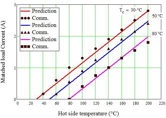
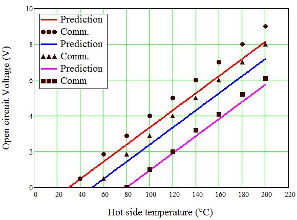
107 (a) (b) (c) 90
 Output power versus hot side temperature, (b) Current versus hot side temperature, (c) Open circuit voltage versus hot side temperature, (d) voltage versus hot side temperature. 5.3.")
108 (d) Figure 5.28: Comparison between calculations with effective material properties and commercial data. (a) Output power versus hot side temperature, (b) Current versus hot side temperature, (c) Open circuit voltage versus hot side temperature, (d) voltage versus hot side temperature Experimental Results Comparing With Analytical Model The overall aim of the experiment is to validate the analytical model that used ideal (standard) equations along with the effective material properties. Using the analytical model of TEG discussed in section along with the experimental setup explained in the last chapter, the analytical model was reasonably verified. The experimental inputs parameters are listed in Table 5.8. However, the voltage and current were measured along with varying the external load resistance while the internal resistance is fixed. Moreover, the junction temperatures (hot and cold sides) are obtained by extrapolating the temperature readings from the aluminum blocks as discussed earlier. Figure 5.29 presents the comparison between analytical and experimental thermoelectric junction temperatures versus a load resistance ratio. The model was reasonably verified although there are some discrepancies. The discrepancies could be attributed to the ideal equations assumptions, except the contact resistances which were included for the effective material properties. 91
109 Table 5.8: Experimental inputs parameters. Description Value Hot inlet temperature (air) 204 Cold inlet temperature (water) 18.4 Mass flow rate (hot side) Volume flow rate (cold side) Total heat transfer rate (hot side) Total heat transfer rate (cold side) g/s 2.8 gpm W W Figure 5.29: Comparison between experimental and analytical junction temperatures versus load resistance ratio. In addition, the comparison between analytical voltage and current with measured voltage and current along the load resistance ratio is shown in Figure It is clear that the measured current 92
110 is in a good agreement with the analytical. On the other hand, the measured voltage is a little more off than the analytical which might be related to the effective material properties where the voltage was not considered. The experimental power output and efficiency are compared to the analytical as shown in Fig.Figure In Figure 5.31 (a), the power output and efficiency were calculated using measured voltage and current, which show small discrepancies related to the voltage. In Figure 5.31 (b), the power output and efficiency were calculated using measured junction temperatures and current along with TE ideal equations, which shows a good agreement. However, the experiment reasonably validated the analytical model due to using of effective material properties. Since the aluminum blocks were used in order to measure the junction temperature, Figure 5.32 shows the power output and efficiency with and without aluminum blocks. It is clear that the system can generate power output of 1.9 W and efficiency of 1.88% without the aluminum blocks. Figure 5.30: Comparison between experimental and analytical current versus load resistance ratio, (b) Comparison between experimental and analytical voltage versus load resistance ratio. 93
111 Figure 5.31: Comparison between experimental and analytical power output and efficiency versus load resistance ratio using voltage and current, (b) Comparison between experimental and analytical power output and efficiency versus load resistance ratio using junction temperatures. 94
112 Figure 5.32: Power output and efficiency with and without aluminum blocks versus load resistance ratio Optimizing and Improving Experimental Work Since the analytical model was verified experimentally, improving the AETEG system is considered. As mentioned, the experimental setup was done based on commercially available equipment. Hence, this section is to investigate the effect of optimizing the TE module, and the hot side heat exchanger and cold side heat exchanger on the performance of system along with same configuration dimensions and mass flow rate Optimizing TE Module The optimum design model was intended to find the maximum possible power output by optimizing the dimensionless load resistance ratio, R r and the ratio of thermal conductance to the convection conductance N k as explained in section 3.3. Fixing hot and cold side parameters, the TE module can be optimized to investigate its effect on system performance. Using the same inputs that were used in the experiment along with dimensionless equations, a simultaneous prediction of the optimum load resistance ratio and geometry ratio can be obtained in order to maximize the power output. The power output and efficiency are plotted versus the dimensionless parameters as shown in Figure The optimum load resistance ratio R r is obtained to be 1.25 along with optimum conductance N k of 0.38, which is the most important parameters. However, using optimum conductance N k, the geometry ratio A e L e can be optimized along with fixing number the of thermocouples n, giving mm. In the same way, the number of thermocouples n can be optimized along with fixing the geometry ratio A e L e, giving 122 couples. Figure 5.34 presents the power output and efficacy versus the optimum number of thermocouples and geometry ratio. 95
 of power output and efficiency are shown in Figure 5.35.")

113 Comparisons between the commercial module used in the experiment and the optimum design (TE module) of power output and efficiency are shown in Figure However, the improvement is about 5.263% in power output, which indicates that the selected commercial module was much closed to the optimum design. (a) (b) (c) (d) 96
 load resistance (b) conductance (c) capacitance at fluid 1 (d) capacitance at fluid 2 (e)")
114 (e) Figure 5.33: Power output and efficiency versus dimensionless (a) load resistance (b) conductance (c) capacitance at fluid 1 (d) capacitance at fluid 2 (e) convectance. (a) (b) Figure 5.34: Power output and efficiency versus (a) optimum number of thermocouples, (b) optimum geometry ratio. 97
115 Figure 5.35: Compression between commercial module used in experiment and optimum design (TE module) of power output and efficiency Optimizing Hot Side Heat Exchanger Due not only to the t TE module limiting the performance, but also the hot and cold side heat exchanger had a considerable effect on it. The hot side heat exchanger was optimized here along with fixing others parameters (TE module and cold side). Using the heat sink optimization discussed earlier, the total heat transfer rate can be optimized as shown in Figure The optimum fin thickness was calculated to be 1.59 mm and the optimum fin thickness is 0.39 mm. Hence, applying these optimum parameters to the model, the improvement can be seen as shown in Figure 5.37, giving an improvement of power output from 1.9 W to 2.1 W, which also indicates that the selected commercial heat sink was close to the optimum. 98
116 Figure 5.36: Total heat transfer rate versus fin thickness (hot side). Figure 5.37: Compression between commercial module used in experiment and optimum design (hot side heat exchanger) of power output and efficiency Optimizing Cold Side Heat Exchanger The third important parameter to consider is the cold side. As mentioned before, the cold side was used without a heat sink. Hence, the effect of using a heat sink ion the cold side is 99
117 investigated along with fixing others parameters (TE module and hot side heat exchanger). The total heat transfer was optimized as shown in Figure 5.38, giving optimum fin thickness of 0.56 mm long with fin spacing of 0.7 mm. After that, applying these optimum parameters to the model, the improvement can be noticed as shown in Figure 5.39 as 3.25 W of power output comparing to 1.9 W. It is a significant improvement comparing to using a channel without heat sink. Figure 5.38: Total heat transfer rate versus fin thickness (cold side). 100
118 Figure 5.39: Compression between commercial module used in experiment and optimum design (cold side heat exchanger) of power output and efficiency. 101
119 Results of All Optimum Parameters Considering the optimization of all parameters, the final optimum design is shown Figure It is clear that the improvement is significant of about %, hence the design of either TE module or hot and cold side heat exchanger is very critical in order the performance. The comparison between the experimental using commercial and the design along with improvement percentage is listed in Table 5.9. Figure 5.40: Comparison between final optimum design and experimental design. 102
120 Table 5.9: Comparison between the experimental using commercial and the optimum design along with improvement percentage Description Experiment TE module Hot side Cold side Final (commercial) optimization optimization optimizatio optimum n design Number of Thermocouples (n) Geometry (G e ) Ratio 2.45 mm mm 2.45 mm 2.45 mm mm Fin Spacing (hot side) (Z) Fin Thickness (hot side) (t) Fin Spacing (cold side) (Z) Fin Thickness (cold side) (t) 1.51 mm 1.51 mm 1.59 mm 1.51 mm 1.59 mm 0.55 mm 0.55 mm 0.39 mm 0.55 mm 0.39 mm 0.7 mm 0.7 mm 0.56 mm 0.56 mm Power Output 1.9 W 2 W 2.16 W 3.2 W 3.5 W Power Density W/cm W/cm W/cm 0.2 W/cm W/cm Improvement Percentage 5.26 % % % % 103
121 6 CONCLUSION AND FUTURE WORK 6.1 Conclusion This current work was focused on the optimization of automotive exhaust thermoelectric generator (AETEG). In this work, analytical models have been developed to calculate the performance of a thermoelectric generator system along with experiment validation. The first part of this thesis deals with the analytical model, using ideal equations where the contact resistances were included. The model was used in order to validate the module test done by GM, which showed a good agreement. Hence, the effect of leg length and ceramic plate materials were investigated. Based on the idea of leg length and ceramic plate materials along with optimizing the hot and cold side heat exchanger, a new design was introduced with a significant improvement in power density when compared to the literature. After that, the new design with a high power density was applied for a 400 kw engine in order to estimate the performance. Moreover, an experiment for one unit cell was conducted to validate the ideal equations model along with using the effective material properties. The model was reasonably verified which indicates the power of using the effective material properties. Hence, the TE module that was used in the experiment was optimized, using a developed dimensionless method. In addition, the optimization of the hot and cold side heat exchanger was considered, which showed their effect on the performance of the system. 6.2 Future Work The effect of the leg length along with ceramic plate materials can be proved experimentally by fabricating a TE module based on the analytical work of this study. The dimensionless method for TE module could be also verified experimentally with a fabricated module based on optimization results. 104
122 The effect of optimization for the hot and cold side heat exchanger can also be validated by using the optimum design results. 105
123 7 References [1] D. Crane and G. Jackson, "Optimization of cross flow heat exchangers for thermoelectric waste heat recovery," Energy Conversion and Management, vol. 45, pp , [2] V. V. Gusev, A. A. Pustovalov, N. N. Rybkin, L. I. Anatychuk. B. N. Demchuk, and I. Y. Ludchak, "Milliwatt-power radioisotope thermoleectric generator (RTG) based on plutonium-238," Journal of Electronic Materials, vol. 40, pp , [3] D. Kraemer et al., "High performance flat-panel solar thermoelectric generators with high thermal concentration," Nature, vol. 10, pp , [4] A.Attar, H. Lee and S. Weera, "Experimental validation of the optimum design of an automotive air-to-air thermoelectric air conditioner (TEAC)," Journal of Electronic Materials, vol. 44, pp , [5] H. Lee, Thermal Design : Heat Sink, Thermoelectrics, Heat Pipes, Compact Heat Exchangers, and Solar Cells, John Wiley & Sons, Inc, [6] H. Lee, Thermoelectrics: Design and Materials, John Wiley, [7] H. Lee, "The Thomson effect and the ideal equation on thermoelectric coolers," Energy, vol. 56, pp , [8] Min, G. and D.M. Row, "Optimisation of thermoelectric module geometry for waste heat electric power generation.," Journal of Power Sources, vol. 38, pp , [9] Min, G., et al, "Determining the electrical and thermal contact resistance of a thermoelectric module," in 11th International Conference on Thermoelectrics, Arlington, Taxas, [10] H. Lee, "Optimal design of thermoelectric devices with dimensional analysis," Applied energy, vol. 106, pp , [11] S.K. Yee, S. LeBlanc, K.E. Goodson, C. Dames, "$ per W metrics for thermoelectric power generation: beyond ZT," Energy Environ Sci, vol. 6, p , [12] Chuang Yu, K.T. Chau, "Thermoelectric automotive waste heat energy recovery," Energy Conversion and Management, vol. 50, p , [13] Yu C., and Chau K. T.,, "Thermoelectric automotive waste heat energy," Energy Convers. Manag, vol. 50, p , [14] Y. J., "Potential applications of thermoelectric waste heat recovery in the," in 24th International Conference on Thermoelectrics,
124 [15] Morelli, Donald T., "Potential Applications of Advanced Thermoelectrics in the Automobile Industry," in 15th International Conference on Thermoelectrics, Warren, [16] Rogl G., Grytsiv A., Bauer E., Rogl P., and Zehetbauer M.,, " Thermoelectric properties of novel skutterudites with didymium: DDy(Fe1 xcox)4sb12 and DDy(Fe1 xnix)4sb12,," Intermetallics,, vol. 18, p , [17] N. A. B., "Portable Thermoelectric Generators," in Society of Automotive, New York, USA, [18] Embary, B. L. and J. R. Tudor, "A Thermoelectric Generator Powered by Engine Exhuast Heat," in Intersociety Energy Conversion Engineering Conference, [19] Birkholz U., Grob E., Stohrer U., Voss K., Gruden D. O., and Wurster W., "Conversion of Waste Exhaust Heat in Automobile using FeSi2 Thermoelements," in 7th International Conference on Thermoelectric Energy Conversion, Arlington,, [20] Bass J., Campana R. J., and Elsner N. B.,, "Thermoelectric Generator Development for Heavy-Duty Truck Applications,," in Technology Development Contractors Coordination Meeting, Dearborn, Michigan, [21] Bass J. C., Elsner N. B., and Leavitt F. A.,, "Performance of the 1 kw thermoelectric generator for diesel engines," in AIP Conf., [22] Ikoma K., Munekiyo M., Furuya K., Kobayashi M., Izumi T., and Shinohara K.,, "Thermoelectric module and generator for gasoline engine vehicles," in XVII International Conference on Thermoelectrics, [23] K. Matsubara, "Development of a High Efficient Thermoelectric Stack for a Waste Exhaust Heat Recovery," in 21st International Conference on Thermoelectronics, Yamaguchi, JAPAN, [24] E F Thacher, B T Helenbrook, M A Karri, C J Richter, "Testing of an automotive exhaust thermoelectric generator in a light truck," in Proceedings of the Institution of Mechanical Engineers, [25] Yu J., and Zhao H.,, "A numerical model for thermoelectric generator with the parallelplate heat exchanger," J. Power Sources, vol. 172, p , [26] Xiao H., Gou X., and Yang C.,, "Simulation analysis on thermoelectric generator system performance," in 7th International Conference on System Simulation and Scientific Computing, [27] Meng F., Chen L., and Sun F.,, "A numerical model and comparative investigation of a thermoelectric generator with multi-irreversibilities," Energy, vol. 36, p ,
125 [28] Espinosa N., Lazard M., Aixala L., and Scherrer H.,, "Modeling a Thermoelectric Generator Applied to Diesel Automotive Heat Recovery," J. Electron. Mater.,, vol. 39, p , [29] Hsiao Y. Y., "A mathematic model of thermoelectric module with applications on waste heat recovery from automobile engine," Energy,, vol. 35, p , [30] Karri M. A., Thacher E. F., and Helenbrook B. T.,, "Exhaust energy conversion by thermoelectric generator: Two case studies," Energy Convers. Manag., vol. 52, p , [31] Eder A., Liebi J., and J nsch D., "Thermoelektrik Eine Chance f r die Automobilindustrie," in Thermoelektrik Eine Chance f r die Automobilindustrie, Renningen, Germany, [32] Kim S., Park S., Kim S., and Rhi S.-H.,, "A Thermoelectric Generator Using Engine Coolant for Light-Duty Internal Combustion Engine-Powered Vehicles," Journal of ELECTRONIC MATERIALS, vol. 40, p , [33] D.T. CRANE, J.W. LaGRANDEUR, F. HARRIS, L.E. BELL, "Performance Results of a High-Power-Density Thermoelectric Generator: Beyond the Couple," Journal of ELECTRONIC MATERIALS, vol. 38, [34] D.T. CRANE, J.W. LAGRANDEUR, "Progress Report on BSST-Led US Department of Energy Automotive Waste Heat Recovery Program," Journal of ELECTRONIC MATERIALS, vol. 39, [35] Y. J., "Engineering and Materials for Automotive Thermoelectric Applications," in Thermoelectrics Applications Workshop, San Diego, CA, [36] J. e. a. Salvador, "Thermal to Electrical Energy Conversion of Skutterudite-Based Thermoelectric Modules," Journal of Electronic Materials, vol. 42, pp , [37] Meisner G. P., "Thermoelectric Conversion of Exhaust Gas Waste Heat into Usable Electricity," in Directions in Engine-Efficiency and Emissions Research (DEER), Detroit, Michigan, [38] M. G. P., "Advanced Thermoelectric Materials and Generator Technology for AutomotiveWaste Heat at GM," in Thermoelectrics Applications Workshop,, San Diego, CA, [39] SUMEET KUMAR et al., "Thermoelectric Generators for Automotive Waste Heat Recovery Systems Part I: Numerical Modeling and Baseline Model Analysis," Journal of ELECTRONIC MATERIALS,
126 [40] SUMEET KUMAR et al., "Thermoelectric Generators for Automotive Waste Heat Recovery Systems Part II: Parametric Evaluation and Topological Studies," Journal of ELECTRONIC MATERIALS, [41] X. Liu, Y.D. Deng, Z. Li, C.Q. Su, "Performance analysis of a waste heat recovery thermoelectric generation system for automotive application," Energy Conversion and Management, vol. 90, [42] Yanliang Zhang et al., "High-temperature and high-power-density nanostructured thermoelectric generator for automotive waste heat recovery," Energy Conversion and Management, vol. 105, p , [43] Tae Young Kim, Assmelash A. Negash, Gyubaek Cho, "Waste heat recovery of a diesel engine using a thermoelectric generator equipped with customized thermoelectric modules," Energy Conversion and Management, vol. 124, pp , [44] Lawrence Livermore National Laboratory and United States Department of Energy, "Annual Energy Review 2015," [45] Abdul Elarusi, Hassan Fagehi, Alaa Attar, HoSung Lee, "Theoretical Approach to Predict the Performance of Thermoelectric Generator Modules," Journal of Electronic Materials, vol. accepted, [46] Teertstra, P., et al, "Analytical forced convection modeling of plate fin heat sinks," in Fifteenth IEEE Semi-Therm Symposium, [47] Gnielinski, V.,, "New equations for heat and mass transfer in turbulent pipe and channel flow," in Int. Chem. Eng., [48] Manglik, R. M. and Bergles, A. E., " Heat Transfer and Pressure Drop Correlations for the Rectangular Offset Strip Fin Compact Heat Exchanger," Experimental Thermal and Fluid Science, vol. 10, pp , [49] Willard W. Pulkrabek, Engineering Fundamentals of the Internal Combustion engine, Prentice Hall, [50] L.E.Bell, "Use of thermal isolation to improve thermoelectric system operating efficiency," in 21st International Conference on Thermoelectronics, [51] "cumminsengines," cummins, Cummins Inc.. [Online]. Available: [Accessed 2016]. 109
127 Appendix A Using balance equations of TEG with two heat sinks Q 1 = m 1 c p,1 (T 1,in T 1,out ) (1) Q 1 = η 1 h 1 A 1 ( T 1,in + T 1,out 2 T 1 ) (2) Q 1 = n [αt 1 I 1 2 RI2 + K(T 1 T 2 )] (3) Q 2 = n [αt 2 I RI2 + K(T 1 T 2 )] (4) Q 2 = η 2 h 2 A 2 (T 2 T 2,in + T 2,out ) (5) 2 Q 2 = m 2 c p,2 (T 2,out T 2,in ) (6) I = α(t 1 T 2 ) R L +R (7) First for Q 1, using Eq. (1) and (2) we have, m 1 c p,1 (T 1,in T 1,out ) = η 1 h 1 A 1 ( T 1,in + T 1,out T 2 1 ) (8) Dividing by η 1 h 1 A 1 we have, m 1 c p,1 (T η 1 h 1 A 1,in T 1,out ) = ( T 1,in + T 1,out T ) (9) Multiplying by η 2h 2 A 2 η 2 h 2 A 2, we have m 1 c p,1 η 2 h 2 A 2 (T η 2 h 2 A 2 η 1 h 1 A 1,in T 1,out ) = ( T 1,in + T 1,out T ) (10) Eq. (10) equals to 1 N m1 (T N 1,in T 1,out ) = ( T 1,in + T 1,out T h 2 1 ) (11) Eq. (11) can be solved for T 1,out, given 110
128 T 1,out = N m1 N T 1,in T 1,in h 2 + T N (12) m1 N h Now, From Eq. (2) and (3) we have, η 1 h 1 A 1 ( T 1,in + T 1,out 2 Inserting Eq. (12) into Eq. (13) T 1 ) = n [αt 1 I 1 2 RI2 + K(T 1 T 2 )] (13) η 1 h 1 A 1 T 1,in 2 N m1 N T 1,in T 1,in h 2 + T N m1 N + h 2 T 1 ( ) = n [αt 1 I 1 2 RI2 + K(T 1 T 2 )] (14) By looking to the right hand side, we have η 1 h 1 A 1 T 1,in 2 N m1 N T 1,in T 1,in h 2 + T N m1 N + h 2 T 1 (15) ( ) Simplifying Eq. (15), we can come up with 1 η 1 h 1 A 1 [ 1 + N ] (T 1,in T 1 ) (16) h 2N m1 Dividing by η 2 h 2 A 2 T 2,in, we have 111
129 N h [ 1 + N ] (T T 1) (17) h 2N m1 Eq. (17) represents the dimensionless equation for the right hand side. Now, for the left hand side we have n [αt 1 I 1 2 RI2 + K(T 1 T 2 )] (18) Where R, K and Z are defined as respectively R = ρl e A e (19) K = ka e L e (20) Inserting Eq. (19), (20) and (7) into Eq. (18) we have α(t 1 T 2 ) n αt 1 R L + ρl e [ A e 1 ρl e 2 ( α(t 1 T 2 ) A e R L + ρl ) e A e 2 + ka e L e (T 1 T 2 ) ] (21) By taking ka e L e as common factor, we have n ka e L e αt 1 α(t 1 T 2 ) R L + ρl e A e ka e L e 1 ρl e 2 A ( α(t 1 T 2 ) e R L + ρl ) e A e 2 ka e L e + (T 1 T 2 ) (22) [ ] Simplifying Eq. (22) and dividing by ρl e A e we have, n ka e L e [ α2 T 1 (T 1 T 2 ) kρ(r r + 1) α2 (T 1 T 2 ) 2 2kρ(R r + 1) 2 + (T 1 T 2 )] (23) Organizing Eq. (23) and dividing by η 2 h 2 A 2 T 2,in, 112
130 N k [ ZT 2,in(T 1 T 2)T 1 R r + 1 ZT 2,in(T 1 T 2) 2 2(R r + 1) 2 + (T 1 T 2)] (24) where Z = α2 kρ (25) Finally, by combining Eq. (17) and (24), we have [ N h 1 + N ] (T T 1) h 2N m1 = N k [ ZT 2,in(T 1 T 2)T 1 R r + 1 ZT 2,in(T 1 T 2) 2 2(R r + 1) 2 + (T 1 T 2)] (26) Eq. (26) represents the first dimensionless equation. First for Q 2, using Eq. (5) and (6) we have, m 2 c p,2 (T 2,out T 2,in ) = η 2 h 2 A 2 (T 2 T 2,in + T 2,out ) (27) 2 Dividing by η 2 h 2 A 2 m 2 c p,2 (T η 2 h 2 A 2,out T 2,in ) = (T 2 T 2,in + T 2,out ) (28) 2 2 Eq. (28) can be written as N m2 (T 2,out T 2,in ) = (T 2 T 2,in + T 2,out ) (29) 2 Solving Eq. (29) for T 2,out T 2,out = T 2 + T 2,in (N m2 1 2 ) N m (30) Now, From Eq. (4) and (5) we have, 113
131 η 2 h 2 A 2 (T 2 T 2,in + T 2,out ) = n [αt 2 2 I RI2 + K(T 1 T 2 )] (31) Inserting Eq. (30) into Eq. (31) T 2 + T 2,in (N m2 1 2 ) η 2 h 2 A 2 T 2 T 2,in 2 + N m ( ) = n [αt 2 I RI2 + K(T 1 T 2 )] (32) By looking to the right hand side, we have T 2 + T 2,in (N m2 1 2 ) η 2 h 2 A 2 T 2 T 2,in 2 + N m (33) ( ) Simplifying Eq. (15), we can come up with η 2 h 2 A 2 ( (T 2 T 2,in ) ( 1 2N m2 ) ) (34) Dividing by η 2 h 2 A 2 T 2,in, we have ( (T 2 1) ( 1 2N m2 ) ) (35) Now, for the left hand side we can follow the same way as before and come up with 114
132 N k [ ZT 2,in(T 1 T 2)T 2 R r + 1 Finally, by combining Eq. (35) and (36), we have + ZT 2,in(T 1 T 2) 2 2(R r + 1) 2 + (T 1 T 2)] (36) ( (T 2 1) 1 + ( 1 ) 2N ) m2 = N k [ ZT 2,in(T 1 T 2)T 2 R r ZT 2,in(T 1 T 2) 2 2(R r + 1) 2 + (T 1 T 2)] (37) where Eq. (37) represents the second dimensionless equation. 115

133 Appendix B 116
Modeling, Optimizing and Testing Thermoelectric Generators for Liquid-to-Liquid Low Grade Waste Heat Recovery
 Western Michigan University ScholarWorks at WMU Master's Theses Graduate College 12-2016 Modeling, Optimizing and Testing Thermoelectric Generators for Liquid-to-Liquid Low Grade Waste Heat Recovery Ali
Analytical Performance Evaluation of Thermoelectric Modules Using Effective Material Properties
 Western Michigan University ScholarWorks at WMU Master's Theses Graduate College 4-2014 Analytical Performance Evaluation of Thermoelectric Modules Using Effective Material Properties Sean Lwe Leslie Weera
A MODEL BASED APPROACH TO EXHAUST THERMOELECTRICS. Quazi Hussain, David Brigham, and Clay Maranville Research & Advanced Engineering
 A MODEL BASED APPROACH TO EXHAUST HEAT RECOVERY USING THERMOELECTRICS Quazi Hussain, David Brigham, and Clay Maranville Research & Advanced Engineering Ford Motor Company Objective Investigate potential
Potential use of Thermoelectric Generator Device for Air Conditioning System
 Potential use of Thermoelectric Generator Device for Air Conditioning System Pedro M. Peralta Trinidad 1, Gerardo Carbajal 1 1 Universidad del Turabo, Puerto Rico, pperalta.engi@gmail.com, gcarbajal1@suagm.edu
Energy Conversion in the Peltier Device
 Laboratory exercise 4 Energy Conversion in the Peltier Device Preface The purpose of this exercise is to become familiar with the Peltier effect. Students will observe Peltier device working as a heat
Thermoelectric effect
 Thermoelectric effect See Mizutani the temperature gradient can also induce an electrical current. linearized Boltzmann transport equation in combination with the relaxation time approximation. Relaxation
Peltier Application Note
 Peltier Application Note Early 19th century scientists, Thomas Seebeck and Jean Peltier, first discovered the phenomena that are the basis for today s thermoelectric industry. Seebeck found that if you
Experiment 1. Measurement of Thermal Conductivity of a Metal (Brass) Bar
 Bar") Experiment 1 Measurement of Thermal Conductivity of a Metal (Brass) Bar Introduction: Thermal conductivity is a measure of the ability of a substance to conduct heat, determined by the rate of heat flow
Experiment 1 Measurement of Thermal Conductivity of a Metal (Brass) Bar Introduction: Thermal conductivity is a measure of the ability of a substance to conduct heat, determined by the rate of heat flow
Validation, Optimization and Simulation of Solar Thermoelectric Generator Model
 1 Validation, Optimization and Simulation of Solar Thermoelectric Generator Model By Ali Hamil Rakesh Krishnappa Harish Hadi Madkhali The Final Project of Thermoelectric I (ME 6590) College of Engineering
Sensing, Computing, Actuating
 Sensing, Computing, ctuating Sander Stuijk (s.stuijk@tue.nl) Department of Electrical Engineering Electronic Systems 2 THERMOELECTRIC EFFECT (Chapter 5.11) 3 Thermocouple cylinder head temperature (thermocouple)
Computational Modeling of a Solar Thermoelectric Generator
 Computational Modeling of a Solar Thermoelectric Generator Undergraduate Thesis Presented in Partial Fulfillment of the Requirements for Graduation with Research Distinction at The Ohio State University
Chapter 3 Thermoelectric Coolers
 3- Capter 3 ermoelectric Coolers Contents Capter 3 ermoelectric Coolers... 3- Contents... 3-3. deal Equations... 3-3. Maximum Parameters... 3-7 3.3 Normalized Parameters... 3-8 Example 3. ermoelectric
THERMOELECTRIC SYSTEM MODELING AND DESIGN
 THERMOELECTRIC SYSTEM MODELING AND DESIGN by Buddhima Pasindu Gamarachchi A thesis submitted in partial fulfillment of the requirements for the degree of Master of Science in Mechanical Engineering Boise
Analysis of Thermoelectric Generator Performance by Use of Simulations and Experiments
 Journal of ELECTRONIC MATERIALS, Vol. 43, No. 6, 2014 DOI: 10.1007/s11664-014-3020-x Ó 2014 The Author(s). This article is published with open access at Springerlink.com Analysis of Thermoelectric Generator
에너지하베스팅의핵심이되는열전소자측정기술 텍트로닉스김수길부장
 에너지하베스팅의핵심이되는열전소자측정기술 텍트로닉스김수길부장 Contents Background of Thermoelectric Device Seebeck Effect/Peltier Effect TE Device Applications TE Device Measurement Instruments 2 Thermoelectric Device Thermoelectric
Available online at ScienceDirect. Energy Procedia 75 (2015 ) Multiphysics Simulations of a Thermoelectric Generator
 Multiphysics Simulations of a Thermoelectric Generator") Available online at www.sciencedirect.com ScienceDirect Energy Procedia 75 (2015 ) 633 638 The 7 th International Conference on Applied Energy ICAE2015 Multiphysics Simulations of a Thermoelectric Generator
Available online at www.sciencedirect.com ScienceDirect Energy Procedia 75 (2015 ) 633 638 The 7 th International Conference on Applied Energy ICAE2015 Multiphysics Simulations of a Thermoelectric Generator
Design Of Thermoelectric Generator from Aluminum and Copper Elements
 IOSR Journal of Mechanical and Civil Engineering (IOSR-JMCE) e-issn: 78-1684,p-ISSN: 30-334X, Volume 13, Issue 5 Ver. VII (Sep. - Oct. 016), PP 60-65 www.iosrjournals.org Design Of Thermoelectric Generator
ELECTRO-THERMAL ANALYSIS OF PELTIER COOLING USING FEM
 ISSN 843-688 Scientific Bulletin of the Electrical Engineering Faculty ear 0 No. (2) ELECTRO-THERMAL ANALSIS OF PELTIER COOLING USING FEM D. ENESCU, E.O. VÎRJOGHE 2, M. IONEL, M.F. STAN 2 Electronic, Telecommunications
Thermal Design. Heat Sinks, Thermoelectrics, Heat Pipes, Compact Heat Exchangers, and Solar Cells. HoSung Lee JOHN WILEY & SONS, INC.
 Thermal Design Thermal Design Heat Sinks, Thermoelectrics, Heat Pipes, Compact Heat Exchangers, and Solar Cells HoSung Lee JOHN WILEY & SONS, INC. This book is printed on acid-free paper. Copyright c
Introduction to Heat and Mass Transfer. Week 5
 Introduction to Heat and Mass Transfer Week 5 Critical Resistance Thermal resistances due to conduction and convection in radial systems behave differently Depending on application, we want to either maximize
Modeling and Applications of Thermoelectric Generators
 Modeling and Applications of Thermoelectric Generators Abdulmohsen A. Alothman Dissertation submitted to the Faculty of the Virginia Polytechnic Institute and State University in partial fulfillment of
Module 4 : THERMOELECTRICITY Lecture 21 : Seebeck Effect
 Module 4 : THERMOELECTRICITY Lecture 21 : Seebeck Effect Objectives In this lecture you will learn the following Seebeck effect and thermo-emf. Thermoelectric series of metals which can be used to form
MAXIMUM NET POWER OUTPUT FROM AN INTEGRATED DESIGN OF A SMALL-SCALE OPEN AND DIRECT SOLAR THERMAL BRAYTON CYCLE. Willem Gabriel le Roux
 MAXIMUM NET POWER OUTPUT FROM AN INTEGRATED DESIGN OF A SMALL-SCALE OPEN AND DIRECT SOLAR THERMAL BRAYTON CYCLE by Willem Gabriel le Roux Submitted in partial fulfilment of the requirements for the degree
OPPA European Social Fund Prague & EU: We invest in your future.
 OPPA European Social Fund Prague & EU: We invest in your future. PELTIER CELL OBJECT Your task is to get acquainted with the Peltier cell behavior in the ThermoElectric Generator mode (TEG) and in the
Heat processes. Heat exchange
 Heat processes Heat exchange Heat energy transported across a surface from higher temperature side to lower temperature side; it is a macroscopic measure of transported energies of molecular motions Temperature
Thermoelectric Energy Harvesting with Carbon Nanotube Systems
 Thermoelectric Energy Harvesting with Carbon Nanotube Systems Presented by Thomas C. Van Vechten, Ph.D. At the New England Nanomanufacturing Summit at UMass Lowell, June 2010 1 Outline Carbon Nanotubes
Chapter 10: Steady Heat Conduction
 Chapter 0: Steady Heat Conduction In thermodynamics, we considered the amount of heat transfer as a system undergoes a process from one equilibrium state to another hermodynamics gives no indication of
If there is convective heat transfer from outer surface to fluid maintained at T W.
 Heat Transfer 1. What are the different modes of heat transfer? Explain with examples. 2. State Fourier s Law of heat conduction? Write some of their applications. 3. State the effect of variation of temperature
A thesis submitted to Cardiff University in the candidature for the degree of Doctor of Philosophy By. Nadhrah Md Yatim, BSc. (Hons), MSc.
, MSc.") Development of Open-Short Circuit Dimensionless Figure-of-Merit (ZT) Measurement Technique for Investigation of Thermoelements and Segmented Thermoelectric Structures A thesis submitted to Cardiff University
Development of Open-Short Circuit Dimensionless Figure-of-Merit (ZT) Measurement Technique for Investigation of Thermoelements and Segmented Thermoelectric Structures A thesis submitted to Cardiff University
Heat Transfer Enhancement Through Perforated Fin
 IOSR Journal of Mechanical and Civil Engineering (IOSR-JMCE) e-issn: 2278-1684,p-ISSN: 2320-334X PP. 72-78 www.iosrjournals.org Heat Transfer Enhancement Through Perforated Fin Noaman Salam, Khan Rahmatullah,
MECH 375, Heat Transfer Handout #5: Unsteady Conduction
 1 MECH 375, Heat Transfer Handout #5: Unsteady Conduction Amir Maleki, Fall 2018 2 T H I S PA P E R P R O P O S E D A C A N C E R T R E AT M E N T T H AT U S E S N A N O PA R T I - C L E S W I T H T U
CHAPTER 5 CONVECTIVE HEAT TRANSFER COEFFICIENT
 62 CHAPTER 5 CONVECTIVE HEAT TRANSFER COEFFICIENT 5.1 INTRODUCTION The primary objective of this work is to investigate the convective heat transfer characteristics of silver/water nanofluid. In order
Supplementary Information for On-chip cooling by superlattice based thin-film thermoelectrics
 Supplementary Information for On-chip cooling by superlattice based thin-film thermoelectrics Table S1 Comparison of cooling performance of various thermoelectric (TE) materials and device architectures
C ONTENTS CHAPTER TWO HEAT CONDUCTION EQUATION 61 CHAPTER ONE BASICS OF HEAT TRANSFER 1 CHAPTER THREE STEADY HEAT CONDUCTION 127
 C ONTENTS Preface xviii Nomenclature xxvi CHAPTER ONE BASICS OF HEAT TRANSFER 1 1-1 Thermodynamics and Heat Transfer 2 Application Areas of Heat Transfer 3 Historical Background 3 1-2 Engineering Heat
HARVESTING HEAT TO CREATE ELECTRICITY: A NEW WORLD RECORD
 HARVESTING HEAT TO CREATE ELECTRICITY: A NEW WORLD RECORD Approximately 90% of world s electricity is generated in turbines moved by hot steam, which, unfortunately, operate only at 30 to 40 percent efficiency.
Maximum Heat Transfer Density From Finned Tubes Cooled By Natural Convection
 Maximum Heat Transfer Density From Finned Tubes Cooled By Natural Convection Ahmed Waheed Mustafa 1 Mays Munir Ismael 2 AL-Nahrain University College of Engineering Mechanical Engineering Department ahmedwah@eng.nahrainuniv.edu.iq
Introduction To Thermoelectrics
 1462 International Drive Traverse City, MI 49686 231-947-0110 www.tellurex.com A Brief History Introduction To Thermoelectrics Early 19th century scientists, Thomas Seebeck and Jean Peltier, first discovered
ELEC9712 High Voltage Systems. 1.2 Heat transfer from electrical equipment
 ELEC9712 High Voltage Systems 1.2 Heat transfer from electrical equipment The basic equation governing heat transfer in an item of electrical equipment is the following incremental balance equation, with
THERMOELECTRICS DESIGN AND MATERIALS
 THERMOELECTRICS THERMOELECTRICS DESIGN AND MATERIALS HoSung Lee Western Michigan University, USA This edition first published 2017 2017 John Wiley & Sons Ltd Registered office John Wiley & Sons Ltd, The
Solar Flat Plate Thermal Collector
 Solar Flat Plate Thermal Collector INTRODUCTION: Solar heater is one of the simplest and basic technologies in the solar energy field. Collector is the heart of any solar heating system. It absorbs and
Device Testing and Characterization of Thermoelectric Nanocomposites
 Device Testing and Characterization of Thermoelectric Nanocomposites By Andrew Muto B.S., Mechanical Engineering (2005) Northeastern University Submitted to the Department of Mechanical Engineering in
Thermal Design of Heat Sink and Optimization of Fin Parameters
 Thermal Design of Heat Sink and Optimization of Fin Parameters Srikanth. V 1, Ramesh.C.G 2 Department of Mechanical Engineering, Sir MVIT, Bangalore, India. 1 Department of Mechanical Engineering, Sir
Current Status and Some Prospects of Thermoelectricity
 Current Status and Some Prospects of Thermoelectricity L.I.Anatychuk Institute of Thermoelectricity General Post Office, Box, Chernivtsi, 00, Ukraine; E-mail: ite@inst.cv.ua; fax: (0-)-9; phone: (0-)-.
Semiconductor thermogenerator
 Semiconductor thermogenerator LEP 4.1.07 Related topics Seebeck effect (thermoelectric effect), thermoelectric e.m.f., efficiency, Peltier coefficient, Thomson coefficient, Seebeck coefficient, direct
Analytical Modeling and Optimization of a Thermoelectric Heat Conversion System Operating Betweeen Fluid Streams
 Brigham Young University BYU ScholarsArchive All Theses and Dissertations 2011-07-13 Analytical Modeling and Optimization of a Thermoelectric Heat Conversion System Operating Betweeen Fluid Streams Stephen
HEAT TRANSFER THERMAL MANAGEMENT OF ELECTRONICS YOUNES SHABANY. C\ CRC Press W / Taylor Si Francis Group Boca Raton London New York
 HEAT TRANSFER THERMAL MANAGEMENT OF ELECTRONICS YOUNES SHABANY C\ CRC Press W / Taylor Si Francis Group Boca Raton London New York CRC Press is an imprint of the Taylor & Francis Group, an informa business
Experimental Comparison of Parametric Characterization Methods for Thermoelectric Generators
 Rochester Institute of Technology RIT Scholar Works Theses Thesis/Dissertation Collections 5-2015 Experimental Comparison of Parametric Characterization Methods for Thermoelectric Generators Reginald D.
Chapter 5 Thomson Effect, Exact Solution, and Compatibility Factor
 5-1 Chapter 5 homson Effect, Exact Solution, and Compatibility Factor he formulation of the classical basic equations for a thermoelectric cooler from the homson relations to the non-linear differential
Numerical analysis of the effects of electrical and thermal configurations of thermoelectric modules in large-scale thermoelectric generators
 *Revised Manuscript with No Changes Marked Click here to download Revised Manuscript with No Changes Marked: AE_full_text_Cozar_01_Rv_1_no_changes.docx 1 1 1 1 1 1 1 1 1 0 1 0 1 0 1 Numerical analysis
Thermo-Hydraulic performance of Internal finned tube Automobile Radiator
 Thermo-Hydraulic performance of Internal finned tube Automobile Radiator Dr.Kailash Mohapatra 1, Deepiarani Swain 2 1 Department of Mechanical Engineering, Raajdhani Engineering College, Bhubaneswar, 751017,
Performance Assessment of PV/T Air Collector by Using CFD
 Performance Assessment of /T Air Collector by Using CFD Wang, Z. Department of Built Environment, University of Nottingham (email: laxzw4@nottingham.ac.uk) Abstract Photovoltaic-thermal (/T) collector,
PERFORMANCE OPTIMIZATION OF HYBRID SOLAR HEATING SYSTEM USING THERMOELECTRIC GENERATOR
 International Journal of Advanced Research in Engineering and Technology (IJARET) Volume 7, Issue 2, March-April 216, pp. 9-2, Article ID: IJARET_7_2_2 Available online at http://www.iaeme.com/ijaret/issues.asp?jtype=ijaret&vtype=7&itype=2
International Journal of Research in Advent Technology, Vol.6, No.11, November 2018 E-ISSN: Available online at
 Comparative analysis of cylindrical and helical coil counter flow type of heat exchanger used in thermoelectric generator for waste heat recovery using CFD fluent Chanchal Kumar 1, a, Dr. Savita Vyas 2,b
TESTING THERMOELECTRIC GENERATORS. Introduction. Test Considerations. Application Note n by Thermoelectric Conversion Systems Limited (TCS)
") TESTING THERMOELECTRIC GENERATORS Application Note n. 2901 by Thermoelectric Conversion Systems Limited (TCS) Introduction Testing the performance of thermoelectric devices in not straightforward for a
TESTING THERMOELECTRIC GENERATORS Application Note n. 2901 by Thermoelectric Conversion Systems Limited (TCS) Introduction Testing the performance of thermoelectric devices in not straightforward for a
Introduction of Nano Science and Tech. Thermal and Electric Conduction in Nanostructures. Nick Fang
 Introduction of Nano Science and Tech Thermal and Electric Conduction in Nanostructures Nick Fang Course Website: nanohub.org Compass.illinois.edu ME 498 2006-09 Nick Fang, University of Illinois. All
NEEDS Thermoelectric Compact Model Documentation Version 1.0.0
 NEEDS Thermoelectric Compact Model Documentation Version 1.0.0 Published on August 31, 2015 Introduction The NEEDS thermoelectric compact model (TEsegment.va) describes a homogeneous segment of thermoelectric
Chapter 3: Fundamentals of Mechanics and Heat. 1/11/00 Electromechanical Dynamics 1
 Chapter 3: Fundamentals of Mechanics and Heat 1/11/00 Electromechanical Dynamics 1 Force Linear acceleration of an object is proportional to the applied force: F = m a x(t) F = force acting on an object
ME 402 GRADUATE PROJECT REPORT ACTIVE BATTERY COOLING SYSTEM FOR ALL-ELECTRIC VEHICLES JINGWEI ZHU
 ME 402 GRADUATE PROJECT REPORT ACTIVE BATTERY COOLING SYSTEM FOR ALL-ELECTRIC VEHICLES BY JINGWEI ZHU Department of Mechanical Science and Engineering University of Illinois at Urbana-Champaign Urbana,
Chapter 7: External Forced Convection. Dr Ali Jawarneh Department of Mechanical Engineering Hashemite University
 Chapter 7: External Forced Convection Dr Ali Jawarneh Department of Mechanical Engineering Hashemite University Objectives When you finish studying this chapter, you should be able to: Distinguish between
Heat and Mass Transfer Prof. S.P. Sukhatme Department of Mechanical Engineering Indian Institute of Technology, Bombay
 Heat and Mass Transfer Prof. S.P. Sukhatme Department of Mechanical Engineering Indian Institute of Technology, Bombay Lecture No. 18 Forced Convection-1 Welcome. We now begin our study of forced convection
Phone: , For Educational Use. SOFTbank E-Book Center, Tehran. Fundamentals of Heat Transfer. René Reyes Mazzoco
 8 Fundamentals of Heat Transfer René Reyes Mazzoco Universidad de las Américas Puebla, Cholula, Mexico 1 HEAT TRANSFER MECHANISMS 1.1 Conduction Conduction heat transfer is explained through the molecular
HEAT TRANSFER BETWEEN AN AUTOMOTIVE EXHAUST AND THERMOELECTRIC MODULES
 HEAT TRANSFER BETWEEN AN AUTOMOTIVE EXHAUST AND THERMOEECTRIC MODUES A.. C. Silva Centro Federal de Educação Tecnológica de Minas Gerais (CEFET-MG) Departamento de Engenharia Mecatrônica Bairro Bela Vista,
Index. a Anisotropic thermoelectric elements 147, 148 Archimedes principle b Benedicks effect 12 Bridgman effect 13
 335 Index a Anisotropic thermoelectric elements 147, 148 Archimedes principle. 191 b Benedicks effect 12 Bridgman effect 13 c Cascaded thermoelectric generators 230 CHI See Constant heat input (CHI) model
4.1 Derivation and Boundary Conditions for Non-Nipped Interfaces
 Chapter 4 Roller-Web Interface Finite Difference Model The end goal of this project is to allow the correct specification of a roller-heater system given a general set of customer requirements. Often the
ABSTRACT. Localized thermoelectric self cooling in semiconductor materials is among the
 ABSTRACT Title of Thesis: HOTSPOT REMEDIATION USING GERMANIUM SELF COOLING TECHNOLOGY Horacio Cesar Nochetto, Masters Of Science, 2011 Thesis Directed By: Professor Avram Bar-Cohen, Department of Mechanical
Spring_#7. Thermodynamics. Youngsuk Nam.
 Spring_#7 Thermodynamics Youngsuk Nam ysnam1@khu.ac.kr You can t connect the dots looking forward; you can only connect them looking backwards. So you have to trust that the dots will somehow connect in
Irwan Setyowidodo 1, Achmad Tri Fadhila 1, Am. Mufarrih 1
 The 3 rd International Seminar on Science and Technology 3 Analysis Effect of Exhaust s Temperature, Total of Peltier s Element and Circuit Type for Thermoelectric Generator Output Voltage at Exhaust Internal
HEAT TRANSFER 1 INTRODUCTION AND BASIC CONCEPTS 5 2 CONDUCTION
 HEAT TRANSFER 1 INTRODUCTION AND BASIC CONCEPTS 5 2 CONDUCTION 11 Fourier s Law of Heat Conduction, General Conduction Equation Based on Cartesian Coordinates, Heat Transfer Through a Wall, Composite Wall
Available online Journal of Scientific and Engineering Research, 2014, 1(2): Research Article
: Research Article") Available online www.jsaer.com, 2014, 1(2):35-43 Research Article ISSN: 2394-2630 ODEN(USA): JSERBR Thermo-economic design and optimization of Parallel-plates ounter flow eat exchanger Mustafa S. Ahmed
Available online www.jsaer.com, 2014, 1(2):35-43 Research Article ISSN: 2394-2630 ODEN(USA): JSERBR Thermo-economic design and optimization of Parallel-plates ounter flow eat exchanger Mustafa S. Ahmed
Non- Iterative Technique for Balancing an. Air Distribution System
 Non- Iterative Technique for Balancing an Air Distribution System Mauro Small Thesis presented to the Faculty of Virginia Polytechnic Institute and State University in partial fulfillment of the requirements
HEAT EXCHANGER. Objectives
 HEAT EXCHANGER Heat exchange is an important unit operation that contributes to efficiency and safety of many processes. In this project you will evaluate performance of three different types of heat exchangers
The Underground Experimental Investigation of Thermocouples
 The Underground Experimental Investigation of Thermocouples April 14, 21 Abstract This experiment investigates a K-type thermocouple in order to demonstrate the Seebeck and Peltier coefficients. Temperature
THERMOELECTRIC PROPERTIES OF V-VI SEMICONDUCTOR ALLOYS AND NANOCOMPOSITES
 THERMOELECTRIC PROPERTIES OF V-VI SEMICONDUCTOR ALLOYS AND NANOCOMPOSITES Submitted by OVGU CEYDA YELGEL to the University of Exeter as a thesis for the degree of Doctor of Philosophy in Physics. August
Low frequency impedance spectroscopy analysis of thermoelectric modules
 Author s accepted copy of the article Journal of Electronic Materials (Published online on march 014) "The final publication is available at Springer via http://dx.doi.org/10.1007/s11664-014-3095-4 Low
Myoung-Soo Kim, Min-Ki Kim, Sung-Eun Jo, Chulmin Joo, and Yong-Jun Kim*
 Supplementary information Refraction-Assisted Solar Thermoelectric Generator based on Phase-Change lens Myoung-Soo Kim, Min-Ki Kim, Sung-Eun Jo, Chulmin Joo, and Yong-Jun Kim* Department of Mechanical
MODELING AND SIMULATION OF BIOHEAT POWERED SUBCUTANEOUS THERMOELECTRIC GENERATOR
 MODELING AND SIMULATION OF BIOHEAT POWERED SUBCUTANEOUS THERMOELECTRIC GENERATOR Ujjwal Verma, Jakob Bernhardt, Dennis Hohlfeld Institute of Electronic Appliances and Circuits University of Rostock, Rostock,
Supplemental Information. Storage and Recycling of Interfacial. Solar Steam Enthalpy
 JOUL, Volume 2 Supplemental Information Storage and Recycling of Interfacial Solar Steam Enthalpy Xiuqiang Li, Xinzhe Min, Jinlei Li, Ning Xu, Pengchen Zhu, Bin Zhu, Shining Zhu, and Jia Zhu Supplemental
ME 105 Mechanical Engineering Laboratory Spring Quarter Experiment #2: Temperature Measurements and Transient Conduction and Convection
 ME 105 Mechanical Engineering Lab Page 1 ME 105 Mechanical Engineering Laboratory Spring Quarter 2010 Experiment #2: Temperature Measurements and Transient Conduction and Convection Objectives a) To calibrate
Laws of Thermodynamics
 Laws of Thermodynamics The Three Laws of Thermodynamics - The first lawof thermodynamics, also called conservation of energy. We can use this knowledge to determine the amount of energy in a system, the
Ceiling Radiant Cooling Panels Employing Heat-Conducting Rails: Deriving the Governing Heat Transfer Equations
 Authors may request permission to reprint or post on their personal or company Web site once the final version of the article has been published. A reprint permission form may be found at www.ashrae.org.
Heat Exchangers for Condensation and Evaporation Applications Operating in a Low Pressure Atmosphere
 Acta Polytechnica Vol. 52 No. 3/202 Heat Exchangers for Condensation and Evaporation Applications Operating in a Low Pressure Atmosphere Petr Kracík,JiříPospíšil, Ladislav Šnajdárek Brno University of
HEAT TRANSFER CAPABILITY OF A THERMOSYPHON HEAT TRANSPORT DEVICE WITH EXPERIMENTAL AND CFD STUDIES
 HEAT TRANSFER CAPABILITY OF A THERMOSYPHON HEAT TRANSPORT DEVICE WITH EXPERIMENTAL AND CFD STUDIES B.M. Lingade a*, Elizabeth Raju b, A Borgohain a, N.K. Maheshwari a, P.K.Vijayan a a Reactor Engineering
Temperature Measurement
 MECE 3320 Measurements & Instrumentation Temperature Measurement Dr. Isaac Choutapalli Department of Mechanical Engineering University of Texas Pan American Introduction Temperature is one of the most
A Metrology for Comprehensive Thermoelectric Device Characterization. Kelly Lofgreen
 A Metrology for Comprehensive Thermoelectric Device Characterization by Kelly Lofgreen A Thesis Presented in Partial Fulfillment of the Requirements for the Degree Master of Science Approved April 2011
Level 7 Post Graduate Diploma in Engineering Heat and mass transfer
 9210-221 Level 7 Post Graduate Diploma in Engineering Heat and mass transfer 0 You should have the following for this examination one answer book non programmable calculator pen, pencil, drawing instruments
Introduction to Heat and Mass Transfer. Week 7
 Introduction to Heat and Mass Transfer Week 7 Example Solution Technique Using either finite difference method or finite volume method, we end up with a set of simultaneous algebraic equations in terms
CHME 302 CHEMICAL ENGINEERING LABOATORY-I EXPERIMENT 302-V FREE AND FORCED CONVECTION
 CHME 302 CHEMICAL ENGINEERING LABOATORY-I EXPERIMENT 302-V FREE AND FORCED CONVECTION OBJECTIVE The objective of the experiment is to compare the heat transfer characteristics of free and forced convection.
Heat and Mass Transfer Unit-1 Conduction
 1. State Fourier s Law of conduction. Heat and Mass Transfer Unit-1 Conduction Part-A The rate of heat conduction is proportional to the area measured normal to the direction of heat flow and to the temperature
Conduction Heat Transfer. Fourier Law of Heat Conduction. x=l Q x+ Dx. insulated x+ Dx. x x. x=0 Q x A
 Conduction Heat Transfer Reading Problems 10-1 10-6 10-20, 10-48, 10-59, 10-70, 10-75, 10-92 10-117, 10-123, 10-151, 10-156, 10-162 11-1 11-2 11-14, 11-20, 11-36, 11-41, 11-46, 11-53, 11-104 Fourier Law
Study of Temperature Distribution Along the Fin Length
 Heat Transfer Experiment No. 2 Study of Temperature Distribution Along the Fin Length Name of the Student: Roll No: Department of Mechanical Engineering for Women, Pune. Aim: ˆ Measuring the temperature
Transient Heat Transfer Experiment. ME 331 Introduction to Heat Transfer. June 1 st, 2017
 Transient Heat Transfer Experiment ME 331 Introduction to Heat Transfer June 1 st, 2017 Abstract The lumped capacitance assumption for transient conduction was tested for three heated spheres; a gold plated
Sustainability in Civil Engineering. II. Power & Heat: Thermodynamics
 Sustainability in Civil Engineering II. Power & Heat: Thermodynamics What is sustainability? What are some manifestations of unsustainability? How does engineering practice need to change? A useful starting
Study on the improved recuperator design used in the direct helium-turbine power conversion cycle of HTR-10
 Study on the improved recuperator design used in the direct helium-turbine power conversion cycle of HTR-10 Wu Xinxin 1), Xu Zhao ) 1) Professor, INET, Tsinghua University, Beijing, P.R.China (xinxin@mail.tsinghua.edu.cn)
 9 th International Conference on Quantitative InfraRed Thermography July 2-5, 2008, Krakow - Poland Application of infrared thermography for validation of numerical analyses results of a finned cross-flow
Introduction to Thermoelectric Materials and Devices
 Introduction to Thermoelectric Materials and Devices 4th Semester of 2012 2012.03.29, Thursday Department of Energy Science Sungkyunkwan University Radioisotope Thermoelectric Generator (PbTe) Space probe
GA A22677 THERMAL ANALYSIS AND TESTING FOR DIII D OHMIC HEATING COIL
 GA A677 THERMAL ANALYSIS AND TESTING FOR DIII D OHMIC HEATING COIL by C.B. BAXI, P.M. ANDERSON, and A.M. GOOTGELD NOVEMBER 1997 DISCLAIMER This report was prepared as an account of work sponsored by an
Solar Thermoelectric Energy Conversion
 Solar Thermoelectric Energy Conversion Gang Chen Massachusetts Institute of Technology Cambridge, MA 02139 Email: gchen2@mit.edu http://web.mit.edu/nanoengineering NSF Nanoscale Science and Engineering
Numerical Analysis of Plate Heat Exchanger Performance in Co-Current Fluid Flow Configuration
 Numerical Analysis of Plate Heat Exchanger Performance in Co-Current Fluid Flow Configuration H. Dardour, S. Mazouz, and A. Bellagi Abstract For many industrial applications plate heat exchangers are demonstrating
Physics 142 Steady Currents Page 1. Steady Currents
 Physics 142 Steady Currents Page 1 Steady Currents If at first you don t succeed, try, try again. Then quit. No sense being a damn fool about it. W.C. Fields Electric current: the slow average drift of
Minhhung Doan, Thanhtrung Dang
 An Experimental Investigation on Condensation in Horizontal Microchannels Minhhung Doan, Thanhtrung Dang Department of Thermal Engineering, Hochiminh City University of Technology and Education, Vietnam