Determination of Flight Loads for the HH-60G Pave Hawk Helicopter
|
|
|
- Stephen Sims
- 5 years ago
- Views:
Transcription

1 Determination of Flight Loads for the HH-60G Pave Hawk Helicopter Robert McGinty, Gregory Wood, Jeff Brenna Mercer Engineering Research Center Warner Robins, GA Steven Lamb US Air Force Robins AFB, GA Aircraft Structural Integrity Conference San Antonio, TX Presented at the, San Antonio, TX,. Copyright 2014 by the ASIP Conference. All rights reserved. Slide 1
2 Background USAF tasked MERC to implement several ASIP initiatives to further improve management of the HH-60G fleet Goal Loads / Environment Spectra Survey (L/ESS) Global Finite Element Model (FEM) Development Flight Strain Survey Durability and Damage Tolerance Analyses (DADTA) Develop an EFH tracking capability, at multiple structural locations, for the fleet Slide 2
3 Motivation ASIP tasks (DADTA, EFH, etc) require correct aircraft loads Structural modifications and mission changes make current HH-60G operations different from original Black Hawk design specifications - Gross weight increase - Engine upgrades - Auxiliary fuel tanks added - Horizontal stab modifications - Refueling probe addition Applicability of original design loads questionable Slide 3

4 Loads Calculation Overview Use data from instrumented flight tests to compute flight loads for HH-60G aircraft to support structural analyses Flight Loads Tail Rotor Forces & Moments Experimental Data MAIN Rotor Forces & Moments Aerodynamic Forces Horizontal Stab Forces & Moments Aerodynamic Forces Stresses Throughout Aircraft Structural strength, fatigue, damage tolerance, and service life analyses Slide 4
 Slide")
5 Flight Strain Survey 63 strain gages 1,000 Hz sample rate Sample Flight Strain Data 30 hours (5,000 regimes) of prescribed maneuvers across operational envelope Operational data also collected, bringing total to 160 hours (30,000 regimes) Slide 5


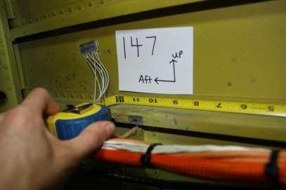
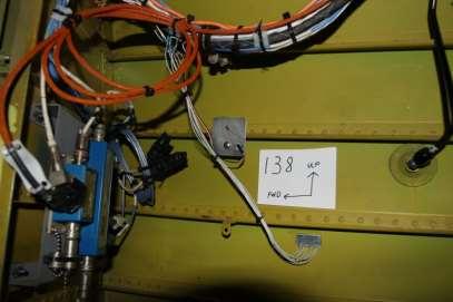
6 Strain Gage Photos Slide 6

7 Finite Element Model HH-60G Finite Element Model - 1,430,000 nodes - 1,050,000 elements - Primarily shell elements - Nominal 1 x 1 element size Slide 7
8 Loads Calculation 1. Apply unit loads to all force / moment locations (one at a time) 2. Execute Nastran inertia relief runs for each unit load to determine its influence on strain at each gage location gives A ij values N j=1 A ij F j = ε i meas where F j are force and moment values 3. Insert experimental ε i values and perform multivariable linear regression to solve for forces and moments 1 equation per gage Significant Forces / Moments j Name FMain z MMain x Main M y Main M z Tail F y FHoriz z Slide 8
9 Loads Calculation (cont) 1. Issue #1 Gages are applied while aircraft is subject to 1G gravity Resolution Modify equation to account for additional strain N j=1 A ij F j = ε i meas + ε i 1G 1 equation per gage where ε i 1G is strain due to 1G gravity (predicted by FE model) 2. Issue #2 Certain forces and moments are closely correlated Resolution Add equations enforcing equilibrium Example M z Main + r CG F y Tail = 0 Slide 9
10 Loads Calculation (cont) Additional complexity Weight and CG change during flight (fuel is burned) This affects the sensitivity coefficients, A ij, and in turn influences the calculated force/moment values The effect is accounted for in calculations F y F z M z F z M y M x F z Slide 10
11 Measured Strain, me 1000 Strain Correlations Accuracy of computed loads is assessed by how well they lead to predicted strains matching measured data Chart for Sym Pull Up shows typical level of correlation (R 2 = 0.94) Predicted Strain, me Slide 11
12 Strain Correlations Alternative view of Sym Pull Up correlation (R 2 = 0.94) Gage locations indicated on structure Blue is predicted Red is measured Slide 12
13 Correlation Coefficients 8,000 7,000 6,000 5,000 Histogram of R 2 values for 30k PITS Average R 2 is and all values are above ,000 3,000 2,000 1, R 2 Slide 13
14 Correlation Coefficients 8,000 7,000 6,000 5,000 4,000 3,000 2,000 Histogram of R 2 values for 30k PITS Average R 2 is and all values are above 0.88 ε i 1G NEGLECTED Effect of 1G gravity loads at time of strain gage application ignored ε i 1G INCORPORATED (same as previous slide) 1, R 2 Slide 14
15 Loads Assessment R 2 values reflect excellent capability to obtain loads producing predicted strains that are closely correlated to measured values - Average R 2 value is But this does not guarantee accurate computed loads - For example, if the entire FE model were too stiff by a factor of 2, then all computed loads would be too high by same factor of 2 Following slides will compare computed loads to flight parameters - Begin with main z-force, F z Main Slide 15
16 Main Rotor Lift Distribution of computed main rotor lift force HH-60G Weight: 15,800 lb -- 21,800 lb 5,000 4,000 3,000 2,000 1, ,000 18,000 20,000 22,000 24,000 26,000 28,000 30,000 Main Rotor Z-Force (lbf) Slide 16
17 % of Regime Occurances Main Rotor Lift Higher forces for pull-ups than push-overs 40% 35% 30% 25% Push Over Level Flight 20% 15% Pull Up 10% 5% 0% Magnitude of Fz (thousands of lbs) Slide 17
 maneuvers Slide")
18 Main Rotor Lift Z-force increases with weight Force is higher for hi-g (Nz) maneuvers Slide 18
19 Main Rotor Lift vs Nz * Weight Excellent 1-to-1 correlation to Nz * Weight Slide 19
20 Main Rotor Lift vs Nz * Weight Gross weight found to be incorrect on Flight 04 (blue points) Slide 20
21 Main Rotor Lift vs Nz * Weight Main Rotor Z-Force correlates very well after gross weight correction Slide 21

22 Main Rotor Mz Correlation Surface plot of Mz versus %Engine Torque and Weight Slide 22
23 Main Rotor Mz Correlation Correlation between Main Z-Moment and Torque * (1 Weight / 30,830) Slide 23
24 Mz - MaxContPowerAccent Main Z-Moment varies significantly for MaxContPwrAscent regime But with knowledge of x-axis value, Mz can be determined much more precisely Variation of Mz for given x-axis value Variation of Mz within regime Slide 24
25 Comparison to Design Loads Main Fz Tail Fy Horiz Fz -7k -1.5k -0.5k -3k -3.6k 0 Design Loads (1970 s) 54k 33k Flight Loads (today) 3.8k 3.4k 4.6k 3k -400k Main Mx -70k 0 300k 100k Main My -1.2M -600k 600k 1.0M Main Mz -1.3M -700k 300k 200k Slide 25

26 Loads Map - Load Case 1 - Load Case 2 High Tail Rotor y-force - Load Case 3 High Horizontal z-force - Load Case 4 Structure is color-coded by load case producing highest stresses/strains in each area Slide 26
27 Summary Forces and moments computed for 30,000 points-in-thesky (over 200 unique regimes) Forces/Moments can now be used for structural analyses, DADTAs, EFH estimates, etc Excellent correlations of predicted and measured strains Excellent correlations of forces and moments to aircraft Torque, Nz, & Weight Forces and moments can be determined much more precisely given Torque, Nz, & Weight than regime ID alone Current My and Mz moments exceed design values Slide 27
28 Future Work Will use a similar process, based on Fourier Transforms and Modal Analyses, to determine dynamic (i.e. vibration) components of loads Addition of dynamic components to average force values presented here will permit Determination of peak maneuver loads Development of load spectra for damage tolerance analyses and probabilistic risk analyses Slide 28
C-130 Usage/Environmental Criteria Analysis and Gust Loads Assessment
 C-130 Usage/Environmental Criteria Analysis and Gust Loads Assessment Dr. Suresh Moon Titan (an L3 Communications Company) Mr. Chance McColl Technical Data Analysis, Inc. Mr. Nam Phan NAVAIR Structures
FEM Validation. 12th January David Schmid Teamleader Structural Analysis
 FEM Validation 12th January 2012 David Schmid Teamleader Structural Analysis FEM Validation and Verification Each FE model which is used to substantiate flight material must be verified Depending on the
Automated Estimation of an Aircraft s Center of Gravity Using Static and Dynamic Measurements
 Proceedings of the IMAC-XXVII February 9-, 009 Orlando, Florida USA 009 Society for Experimental Mechanics Inc. Automated Estimation of an Aircraft s Center of Gravity Using Static and Dynamic Measurements
Improving the Accuracy of Dynamic Vibration Fatigue Simulation
 Improving the Accuracy of Dynamic Vibration Fatigue Simulation Kurt Munson HBM Prenscia Agenda 2 1. Introduction 2. Dynamics and the frequency response function (FRF) 3. Using finite element analysis (FEA)
Full Scale Structural Durability Test Spectrum Reduction by Truncation Coupon Testing
 Full Scale Structural Durability Test Spectrum Reduction by Truncation Coupon Testing Ogewu C. Agbese F-16/F-22 IFG Service Life Analysis Lockheed Martin Aeronautics Fort Worth, TX, USA ogewu.c.agbese@lmco.com
DEPARTMENT OF AEROSPACE ENGINEERING, IIT MADRAS M.Tech. Curriculum
 DEPARTMENT OF AEROSPACE ENGINEERING, IIT MADRAS M.Tech. Curriculum SEMESTER I AS5010 Engg. Aerodyn. & Flt. Mech. 3 0 0 3 AS5020 Elements of Gas Dyn. & Propln. 3 0 0 3 AS5030 Aircraft and Aerospace Structures
PROGRESS IN THE PREDICTION OF AEROSERVOELASTIC INSTABILITIES ON LARGE CIVIL TRANSPORT AIRCRAFT
 ICAS 2000 CONGRESS PROGRESS IN THE PREDICTION OF AEROSERVOELASTIC INSTABILITIES ON LARGE CIVIL TRANSPORT AIRCRAFT M.LACABANNE, A.LAPORTE AEROSPATIALE MATRA AIRBUS, 31060 Toulouse Cedex 03, France Abstract
3. Overview of MSC/NASTRAN
 3. Overview of MSC/NASTRAN MSC/NASTRAN is a general purpose finite element analysis program used in the field of static, dynamic, nonlinear, thermal, and optimization and is a FORTRAN program containing
Calculating the Risk of Structural Failure
 Calculating the Risk of Structural Failure Presentation at Society of Reliability Engineers Meeting December 9, 2015 Bob Graber STARGroup Solutions, LLC robert.graber@stargroup.solutions Designing a Structure
Two Tier projects for students in ME 160 class
 ME 160 Introduction to Finite Element Method Spring 2016 Topics for Term Projects by Teams of 2 Students Instructor: Tai Ran Hsu, Professor, Dept. of Mechanical engineering, San Jose State University,
However, reliability analysis is not limited to calculation of the probability of failure.
 Probabilistic Analysis probabilistic analysis methods, including the first and second-order reliability methods, Monte Carlo simulation, Importance sampling, Latin Hypercube sampling, and stochastic expansions
Aeroelastic Gust Response
 Aeroelastic Gust Response Civil Transport Aircraft - xxx Presented By: Fausto Gill Di Vincenzo 04-06-2012 What is Aeroelasticity? Aeroelasticity studies the effect of aerodynamic loads on flexible structures,
Aircraft Design I Tail loads
 Horizontal tail loads Aircraft Design I Tail loads What is the source of loads? How to compute it? What cases should be taken under consideration? Tail small wing but strongly deflected Linearized pressure
Aircraft Structures Design Example
 University of Liège Aerospace & Mechanical Engineering Aircraft Structures Design Example Ludovic Noels Computational & Multiscale Mechanics of Materials CM3 http://www.ltas-cm3.ulg.ac.be/ Chemin des Chevreuils
Stability and Control Some Characteristics of Lifting Surfaces, and Pitch-Moments
 Stability and Control Some Characteristics of Lifting Surfaces, and Pitch-Moments The lifting surfaces of a vehicle generally include the wings, the horizontal and vertical tail, and other surfaces such
Luncheon Keynote Address #1: An Engineer's Education and It's Use in Aerospace
 Georgia Southern University Digital Commons@Georgia Southern Interdisciplinary STEM Teaching & Learning Conference Mar 6th, 12:30 PM - 12:50 PM Luncheon Keynote Address #1: An Engineer's Education and
ScienceDirect. Fatigue life from sine-on-random excitations
 Available online at www.sciencedirect.com ScienceDirect Procedia Engineering 101 (2015 ) 235 242 3rd International Conference on Material and Component Performance under Variable Amplitude Loading, VAL2015
Chapter 2. Formulation of Finite Element Method by Variational Principle
 Chapter 2 Formulation of Finite Element Method by Variational Principle The Concept of Variation of FUNCTIONALS Variation Principle: Is to keep the DIFFERENCE between a REAL situation and an APPROXIMATE
Chapter 1 General Introduction Instructor: Dr. Mürüde Çelikağ Office : CE Building Room CE230 and GE241
 CIVL222 STRENGTH OF MATERIALS Chapter 1 General Introduction Instructor: Dr. Mürüde Çelikağ Office : CE Building Room CE230 and GE241 E-mail : murude.celikag@emu.edu.tr 1. INTRODUCTION There are three
VIBRATION ENERGY FLOW IN WELDED CONNECTION OF PLATES. 1. Introduction
 ARCHIVES OF ACOUSTICS 31, 4 (Supplement), 53 58 (2006) VIBRATION ENERGY FLOW IN WELDED CONNECTION OF PLATES J. CIEŚLIK, W. BOCHNIAK AGH University of Science and Technology Department of Robotics and Mechatronics
Fleet Usage Spectrum Evaluation & Mission Classification
 Fleet Usage Spectrum Evaluation & Mission Classification 1 Background Design Process C-130 Application Results Summary 2 3 Background Usage Description Measurement of parameters which are representative
Static and Dynamic Analysis of mm Steel Last Stage Blade for Steam Turbine
 Applied and Computational Mechanics 3 (2009) 133 140 Static and Dynamic Analysis of 1 220 mm Steel Last Stage Blade for Steam Turbine T. Míšek a,,z.kubín a aškoda POWER a. s., Tylova 57, 316 00 Plzeň,
Tracker Tower 01 Prototype Test & Analysis Overview
 Tracker Tower 01 Prototype Test & Analysis Overview Erik Swensen June 19, 2002 HPS-102070-0002 Test Background Design Philosophy: Tracker Tower 01 Prototype was used as an engineering evaluation model
Chapter Objectives. Copyright 2011 Pearson Education South Asia Pte Ltd
 Chapter Objectives To develop the equations of equilibrium for a rigid body. To introduce the concept of the free-body diagram for a rigid body. To show how to solve rigid-body equilibrium problems using
16.07 Dynamics Final Exam
 Name:... Massachusetts Institute of Technology 16.07 Dynamics Final Exam Tuesday, December 20, 2005 Problem 1 (8) Problem 2 (8) Problem 3 (10) Problem 4 (10) Problem 5 (10) Problem 6 (10) Problem 7 (10)
Appendix A Satellite Mechanical Loads
 Appendix A Satellite Mechanical Loads Mechanical loads can be static or dynamic. Static loads are constant or unchanging, and dynamic loads vary with time. Mechanical loads can also be external or self-contained.
Aircraft Performance, Stability and control with experiments in Flight. Questions
 Aircraft Performance, Stability and control with experiments in Flight Questions Q. If only the elevator size of a given aircraft is decreased; keeping horizontal tail area unchanged; then the aircraft
Response Spectrum Analysis Shock and Seismic. FEMAP & NX Nastran
 Response Spectrum Analysis Shock and Seismic FEMAP & NX Nastran Table of Contents 1. INTRODUCTION... 3 2. THE ACCELEROGRAM... 4 3. CREATING A RESPONSE SPECTRUM... 5 4. NX NASTRAN METHOD... 8 5. RESPONSE
Aero-Propulsive-Elastic Modeling Using OpenVSP
 Aero-Propulsive-Elastic Modeling Using OpenVSP August 8, 213 Kevin W. Reynolds Intelligent Systems Division, Code TI NASA Ames Research Center Our Introduction To OpenVSP Overview! Motivation and Background!
THERMOWELL VIBRATION INVESTIGATION AND ANALYSIS
 THERMOWELL VIBRATION INVESTIGATION AND ANALYSIS Michael A. Porter Dynamic Analysis 815 Stratford Road Lawrence, Kansas 66049 785-843-3558 mike@dynamicanalysis.com www.dynamicanalysis.com Dennis H. Martens
Low-Order Aero-Structural Analysis Using OpenVSP and ASWing
 Low-Order Aero-Structural Analysis Using OpenVSP and ASWing Erik Olson, Ph.D. NASA-Langley Research Center Quinten Henricks, B.S. Ohio State University OpenVSP Workshop 2017 Outline Background & Motivation
AERSYS KNOWLEDGE UNIT
 -7016 1. INTRODUCTION The scope of this document is to provide a clarification and a deeper understanding of the two different ways to move the mid plane of the element out of the nodal plane. Although
Load and Stress Spectrum Generation
 Load and Stress Spectrum Generation During 1962, at the request of the FAA, and upon recommendation of the National Aeronautics and Space Administration (NASA) Committee on Aircraft Operating Problems,
NATURAL FREQUENCIES OF A HONEYCOMB SANDWICH PLATE Revision F. A diagram of a honeycomb plate cross-section is shown in Figure 1.
 NATURAL FREQUENCIES OF A HONEYCOMB SANDWICH PLATE Revision F By Tom Irvine Email: tomirvine@aol.com August 5, 008 Bending Stiffness of a Honeycomb Sandwich Plate A diagram of a honeycomb plate cross-section
Model-Based Engineering and Cyber-Physical Systems
 Model-Based Engineering and Cyber-Physical Systems Jason Hatakeyama Chief Architect Boeing Defense, Space & Security Approved for public release 8/2/17. Ref no. 17-00606-BDS. GPDIS_2017.ppt 1 PRODUCT CONCEPT
Generation X. Attitude Control Systems (ACS) Aprille Ericsson Dave Olney Josephine San. July 27, 2000
 Aprille Ericsson Dave Olney Josephine San. July 27, 2000") Generation X Attitude Control Systems (ACS) Aprille Ericsson Dave Olney Josephine San July 27, 2000 ACS Overview Requirements Assumptions Disturbance Torque Assessment Component and Control Mode Recommendations
Generation X Attitude Control Systems (ACS) Aprille Ericsson Dave Olney Josephine San July 27, 2000 ACS Overview Requirements Assumptions Disturbance Torque Assessment Component and Control Mode Recommendations
EFFECTIVITY PAGE DATE ISSUE PAGE DATE ISSUE PAGE DATE ISSUE 24/07/14 24/07/14
 173 ROCHEFORT FAX: (33) 5 46 87 4 12 EFFECTIVITY PAGE DATE ISSUE PAGE DATE ISSUE PAGE DATE ISSUE 1 2 3 4 5 6 7 8 9 1 11 12 13 14 15 16 17 18 19 2 21 22 23 24 25 26 27 28 29 3 24/7/14 24/7/14 24/7/14 24/7/14
Dynamic Response of an Aircraft to Atmospheric Turbulence Cissy Thomas Civil Engineering Dept, M.G university
 Dynamic Response of an Aircraft to Atmospheric Turbulence Cissy Thomas Civil Engineering Dept, M.G university cissyvp@gmail.com Jancy Rose K Scientist/Engineer,VSSC, Thiruvananthapuram, India R Neetha
Impact and Fracture Mechanics Assessment of a Fused Silica Window
 Arnold AFB Wind Tunnel Impact and Fracture Mechanics Analysis Rev-0 1 of 41 Impact and Fracture Mechanics Assessment of a Fused Silica Window Objective: Determine the survival probability of a fused silica
Sizing Thermowell according to ASME PTC 19.3
 Products Solutions Services Sizing Thermowell according to ASME PTC 19.3 AIS 2015 17th September Endress+Hauser Pessano c. Bornago Slide 1 SUMMARY Why is stress thermowell calculation necessary? Loading
Dynamic Stress Analysis of a Bus Systems
 Dynamic Stress Analysis of a Bus Systems *H. S. Kim, # Y. S. Hwang, # H. S. Yoon Commercial Vehicle Engineering & Research Center Hyundai Motor Company 772-1, Changduk, Namyang, Whasung, Kyunggi-Do, Korea
EMA 545 Final Exam - Prof. M. S. Allen Spring 2011
 EMA 545 Final Exam - Prof. M. S. Allen Spring 2011 Honor Pledge: On my honor, I pledge that this exam represents my own work, and that I have neither given nor received inappropriate aid in the preparation
Automatic Aircraft Cargo Load Planning
 Automatic Aircraft Cargo Load Planning Sabine Limbourg QuantOM-HEC-University of Liège Michaël Schyns QuantOM-HEC-University of Liège Gilbert Laporte CIRRELT HEC Montréal Agenda Problem statement Constraints
Estimation of Unsteady Loading for Sting Mounted Wind Tunnel Models
 52nd AIAA/ASME/ASCE/AHS/ASC Structures, Structural Dynamics and Materials Conference 19th 4-7 April 2011, Denver, Colorado AIAA 2011-1941 Estimation of Unsteady Loading for Sting Mounted Wind Tunnel
In this lecture you will learn the following
 Module 9 : Forced Vibration with Harmonic Excitation; Undamped Systems and resonance; Viscously Damped Systems; Frequency Response Characteristics and Phase Lag; Systems with Base Excitation; Transmissibility
The Truth About Elliptic Spanloads or Optimum Spanloads Incorporating Wing Structural Weight
 The Truth About Elliptic Spanloads or Optimum Spanloads Incorporating Wing Structural Weight Sergio Iglesias and William H. Mason AIAA Paper 2001-5234 as presented at the 1st AIAA Aircraft Technology,
Shafts: Torsion of Circular Shafts Reading: Crandall, Dahl and Lardner 6.2, 6.3
 M9 Shafts: Torsion of Circular Shafts Reading: Crandall, Dahl and Lardner 6., 6.3 A shaft is a structural member which is long and slender and subject to a torque (moment) acting about its long axis. We
Fundamentals of Durability. Unrestricted Siemens AG 2013 All rights reserved. Siemens PLM Software
 Fundamentals of Durability Page 1 Your single provider of solutions System simulation solutions 3D simulation solutions Test-based engineering solutions Engineering services - Deployment services Troubleshooting
Fatigue Crack Analysis on the Bracket of Sanding Nozzle of CRH5 EMU Bogie
 Journal of Applied Mathematics and Physics, 2015, 3, 577-583 Published Online May 2015 in SciRes. http://www.scirp.org/journal/jamp http://dx.doi.org/10.4236/jamp.2015.35071 Fatigue Crack Analysis on the
EVAPRED A CODE FOR FATIGUE ANALYSIS OPTIMIZATION
 EVAPRED A CODE FOR FATIGUE ANALYSIS OPTIMIZATION Dorin LOZICI-BRÎNZEI, INCAS, lozicid@incas.ro Simion TǍTARU, INCAS, sitataru@incas.ro DOI: 10.13111/2066-8201.2010.2.1.4 Abstract The fatigue can be, in
FLUTTER PREDICTION OF A SWEPT BACK PLATE USING EXPERIMENTAL MODAL PARAMETERS
 Symposium on Applied Aerodynamics and Design of Aerospace Vehicle (SAROD 2011) November 16-18, 2011, Bangalore, India FLUTTER PREDICTION OF A SWEPT BACK PLATE USING EXPERIMENTAL MODAL PARAMETERS A.C.Pankaj*,
Advanced Software for Integrated Probabilistic Damage Tolerance Analysis Including Residual Stress Effects
 Advanced Software for Integrated Probabilistic Damage Tolerance Analysis Including Residual Stress Effects Residual Stress Summit 2010 Tahoe City, California September 26-29, 2010 Michael P. Enright R.
The science of elasticity
 The science of elasticity In 1676 Hooke realized that 1.Every kind of solid changes shape when a mechanical force acts on it. 2.It is this change of shape which enables the solid to supply the reaction
Finite Element Method in Geotechnical Engineering
 Finite Element Method in Geotechnical Engineering Short Course on + Dynamics Boulder, Colorado January 5-8, 2004 Stein Sture Professor of Civil Engineering University of Colorado at Boulder Contents Steps
2008 International ANSYS Conference
 2008 International ANSYS Conference Using FEA Results To Determine Stress Concentration Factors W.D. Growney Engineering Specialist Eaton Aerospace, Conveyance Systems Division 2008 ANSYS, Inc. All rights
ε t increases from the compressioncontrolled Figure 9.15: Adjusted interaction diagram
 CHAPTER NINE COLUMNS 4 b. The modified axial strength in compression is reduced to account for accidental eccentricity. The magnitude of axial force evaluated in step (a) is multiplied by 0.80 in case
Linear guide drives. Synchronous shafts The use of synchronous shafts enables several linear axes to be operated with one drive.
 Linear guide drives Drive concept The linear guides are driven via the hollow shaft in the drive head. The drive head is used to directly install a motor or alternatively (in connection with a center shaft)
MECHANICS OF MATERIALS. Prepared by Engr. John Paul Timola
 MECHANICS OF MATERIALS Prepared by Engr. John Paul Timola Mechanics of materials branch of mechanics that studies the internal effects of stress and strain in a solid body. stress is associated with the
Introduction to Aerospace Engineering
 Introduction to Aerospace Engineering Lecture slides Challenge the future 1 Aircraft & spacecraft loads Translating loads to stresses Faculty of Aerospace Engineering 29-11-2011 Delft University of Technology
SENSITIVITY ANALYSIS OF ADAPTIVE MAGNITUDE SPECTRUM ALGORITHM IDENTIFIED MODAL FREQUENCIES OF REINFORCED CONCRETE FRAME STRUCTURES
 SENSITIVITY ANALYSIS OF ADAPTIVE MAGNITUDE SPECTRUM ALGORITHM IDENTIFIED MODAL FREQUENCIES OF REINFORCED CONCRETE FRAME STRUCTURES K. C. G. Ong*, National University of Singapore, Singapore M. Maalej,
Power output: 6 750kW=4500kW Location: Top of Taikoyama, Kyoto prefecture, Japan. Terrain condition: Complex mountainous area
 Introduction Power output: 6 75kW=45kW Location: Top of Taikoyama, Kyoto prefecture, Japan 1 2 3 4 5 6 5m 45.94m Fracture section Terrain condition: Complex mountainous area m History: Nov, 21: Power generation
D : SOLID MECHANICS. Q. 1 Q. 9 carry one mark each.
 GTE 2016 Q. 1 Q. 9 carry one mark each. D : SOLID MECHNICS Q.1 single degree of freedom vibrating system has mass of 5 kg, stiffness of 500 N/m and damping coefficient of 100 N-s/m. To make the system
5. What is the moment of inertia about the x - x axis of the rectangular beam shown?
 1 of 5 Continuing Education Course #274 What Every Engineer Should Know About Structures Part D - Bending Strength Of Materials NOTE: The following question was revised on 15 August 2018 1. The moment
Chapter 4. The Laws of Motion. Dr. Armen Kocharian
 Chapter 4 The Laws of Motion Dr. Armen Kocharian Classical Mechanics Describes the relationship between the motion of objects in our everyday world and the forces acting on them Conditions when Classical
STATICS. FE Review. Statics, Fourteenth Edition R.C. Hibbeler. Copyright 2016 by Pearson Education, Inc. All rights reserved.
 STATICS FE Review 1. Resultants of force systems VECTOR OPERATIONS (Section 2.2) Scalar Multiplication and Division VECTOR ADDITION USING EITHER THE PARALLELOGRAM LAW OR TRIANGLE Parallelogram Law: Triangle
Numerical simulation the bottom structures. grounding test by LS-DYNA
 5 th European LS-DYNA Users Conference Methods and Techniques (3) Numerical simulation the bottom structures grounding test by LS-DYNA Ainian Zhang Graduate School of Frontier Sciences, The University
Robustness - Offshore Wind Energy Converters
 Robustness of Structures - February 4-5, 2008, Zurich 1-14 Robustness - Offshore Wind Energy Converters Sebastian Thöns Risk and Safety, Institute of Structural Engineering (IBK) ETH Zurich Division VII.2:
Analysis of Blocky Rock Slopes with Finite Element Shear Strength Reduction Analysis
 Analysis of Blocky Rock Slopes with Finite Element Shear Strength Reduction Analysis R.E. Hammah, T. Yacoub, B. Corkum & F. Wibowo Rocscience Inc., Toronto, Canada J.H. Curran Department of Civil Engineering
Rotor reference axis
 Rotor reference axis So far we have used the same reference axis: Z aligned with the rotor shaft Y perpendicular to Z and along the blade (in the rotor plane). X in the rotor plane and perpendicular do
Hypersonic Vehicle (HSV) Modeling
 Modeling") Hypersonic Vehicle (HSV) Modeling Carlos E. S. Cesnik Associate Professor of Aerospace Engineering University of Michigan, Ann Arbor HSV Concentration MA Kickoff Meeting Ann Arbor, 29 August 2007 Team
Hypersonic Vehicle (HSV) Modeling Carlos E. S. Cesnik Associate Professor of Aerospace Engineering University of Michigan, Ann Arbor HSV Concentration MA Kickoff Meeting Ann Arbor, 29 August 2007 Team
Random Vibration Analysis in FEMAP An Introduction to the Hows and Whys
 Random Vibration Analysis in FEMAP An Introduction to the Hows and Whys Adrian Jensen, PE Senior Staff Mechanical Engineer Kyle Hamilton Staff Mechanical Engineer Table of Contents 1. INTRODUCTION... 4
Extending Transducer Calibration Range by Extrapolation
 Introduction Extending Transducer Calibration by olation by LaVar Clegg Force and torque transducers must be calibrated in a laboratory in order to be useful in their intended application. Applications
3 JAA Special Publication JAA-SP-6-8E efficiency of damping estimation. It is pointed out, however, that damping is not always an appropriate index to
 First International Symposium on Flutter and its Application, 6 3 ETENSION OF DISCRETE-TIME FLUTTER PREDICTION METHOD TO A HIGHER-MODE SYSTEM Hiroshi Torii + Meijo University, Nagoya, Japan Conventionally
Predicting Fatigue Life with ANSYS Workbench
 Predicting Fatigue Life with ANSYS Workbench How To Design Products That Meet Their Intended Design Life Requirements Raymond L. Browell, P. E. Product Manager New Technologies ANSYS, Inc. Al Hancq Development
Wind data collected by a fixed-wing aircraft in the vicinity of a typhoon over the south China coastal waters
 Wind data collected by a fixed-wing aircraft in the vicinity of a typhoon over the south China coastal waters P.W. Chan * and K.K. Hon Hong Kong Observatory, Hong Kong, China Abstract: The fixed-wing aircraft
Finite Element Analysis Prof. Dr. B. N. Rao Department of Civil Engineering Indian Institute of Technology, Madras. Module - 01 Lecture - 13
 Finite Element Analysis Prof. Dr. B. N. Rao Department of Civil Engineering Indian Institute of Technology, Madras (Refer Slide Time: 00:25) Module - 01 Lecture - 13 In the last class, we have seen how
Airbus Quantum Computing Challenge
 Airbus Quantum Computing Challenge Bringing Flight Physics into the Quantum Era CHALLENGES Flight physics, the broad denomination of all scientific and engineering aspects related to the flight of aircraft,
1942. Effects of motion-induced aerodynamic force on the performance of active buffeting control
 1942. Effects of motion-induced aerodynamic force on the performance of active buffeting control Jie Sun 1, Min Li 2 School of Aeronautic Science and Engineering, Beijing University of Aeronautics and
Torsion of Solid Sections. Introduction
 Introduction Torque is a common load in aircraft structures In torsion of circular sections, shear strain is a linear function of radial distance Plane sections are assumed to rotate as rigid bodies These
PROBLEM Copyright McGraw-Hill Education. Permission required for reproduction or display. SOLUTION
 PROLEM 7. The rotor of an electric motor has an angular velocity of 600 rpm when the load and power are cut off. The 0-lb rotor, which has a centroidal radius of gyration of 9 in., then coasts to rest.
Final Examination Thursday May Please initial the statement below to show that you have read it
 EN40: Dynamics and Vibrations Final Examination Thursday May 0 010 Division of Engineering rown University NME: General Instructions No collaboration of any kind is permitted on this examination. You may
AEROTAXI ground static test and finite element model validation
 AEROTAXI ground static test and finite element model validation Dorin LOZICI-BRINZEI* 1, Simion TATARU, Radu BISCA 1 *Corresponding author * 1 INCAS - National Institute for Aerospace Research Elie Carafoli
RELIABILITY OF FLEET OF AIRCRAFT
 Session 2. Reliability and Maintenance Proceedings of the 12 th International Conference Reliability and Statistics in Transportation and Communication (RelStat 12), 17 2 October 212, Riga, Latvia, p.
Chapter 13. Simple Harmonic Motion
 Chapter 13 Simple Harmonic Motion Hooke s Law F s = - k x F s is the spring force k is the spring constant It is a measure of the stiffness of the spring A large k indicates a stiff spring and a small
MULTIDISCPLINARY OPTIMIZATION AND SENSITIVITY ANALYSIS OF FLUTTER OF AN AIRCRAFT WING WITH UNDERWING STORE IN TRANSONIC REGIME
 MULTIDISCPLINARY OPTIMIZATION AND SENSITIVITY ANALYSIS OF FLUTTER OF AN AIRCRAFT WING WITH UNDERWING STORE IN TRANSONIC REGIME A thesis submitted in partial fulfillment of the requirements for the degree
Advanced Friction Modeling in Sheet Metal Forming
 Advanced Friction Modeling in Sheet Metal Forming J.Hol 1,a, M.V. Cid Alfaro 2, T. Meinders 3, J. Huétink 3 1 Materials innovation institute (M2i), P.O. box 58, 26 GA Delft, The Netherlands 2 Tata Steel
Development of Reliability-Based Damage Tolerant Structural Design Methodology
 Development of Reliability-Based Damage Tolerant Structural Design Methodology Presented by Dr. Kuen Y. Lin and Dr. Andrey Styuart Department of Aeronautics and Astronautics University of Washington, Box
FLIGHT DYNAMICS. Robert F. Stengel. Princeton University Press Princeton and Oxford
 FLIGHT DYNAMICS Robert F. Stengel Princeton University Press Princeton and Oxford Preface XV Chapter One Introduction 1 1.1 ELEMENTS OF THE AIRPLANE 1 Airframe Components 1 Propulsion Systems 4 1.2 REPRESENTATIVE
Physics 125, Spring 2006 Monday, May 15, 8:00-10:30am, Old Chem 116. R01 Mon. 12:50 R02 Wed. 12:50 R03 Mon. 3:50. Final Exam
 Monday, May 15, 8:00-10:30am, Old Chem 116 Name: Recitation section (circle one) R01 Mon. 12:50 R02 Wed. 12:50 R03 Mon. 3:50 Closed book. No notes allowed. Any calculators are permitted. There are no trick
Estimating Structural Response to Random Vibration: Reaction Forces
 Estimating Structural Response to Random Vibration: Reaction Forces Alex Grishin, Consulting Engineer PADT, Tempe AZ ANSYS Release 17.0 (January, 2016) Among the various enhancements, users may now estimate
A HIGHER-ORDER BEAM THEORY FOR COMPOSITE BOX BEAMS
 A HIGHER-ORDER BEAM THEORY FOR COMPOSITE BOX BEAMS A. Kroker, W. Becker TU Darmstadt, Department of Mechanical Engineering, Chair of Structural Mechanics Hochschulstr. 1, D-64289 Darmstadt, Germany kroker@mechanik.tu-darmstadt.de,
9.4 Life Sensitivity for Stress Effects
 9.4 Life Sensitivity for Stress Effects The fatigue crack growth life of structural components is significantly affected by the level of applied (repeating) stress and the initial crack size. This section
Dynamics of assembled structures of rotor systems of aviation gas turbine engines of type two-rotor
 Dynamics of assembled structures of rotor systems of aviation gas turbine engines of type two-rotor Anatoly А. Pykhalov 1, Mikhail А. Dudaev 2, Mikhail Ye. Kolotnikov 3, Paul V. Makarov 4 1 Irkutsk State
/ m U) β - r dr/dt=(n β / C) β+ (N r /C) r [8+8] (c) Effective angle of attack. [4+6+6]
![/ m U) β - r dr/dt=(n β / C) β+ (N r /C) r [8+8] (c) Effective angle of attack. [4+6+6]](/thumbs/91/105418625.jpg "/ m U) β - r dr/dt=(n β / C) β+ (N r /C) r [8+8] (c) Effective angle of attack. [4+6+6]") Code No: R05322101 Set No. 1 1. (a) Explain the following terms with examples i. Stability ii. Equilibrium. (b) Comment upon the requirements of stability of a i. Military fighter aircraft ii. Commercial
Code No: R05322101 Set No. 1 1. (a) Explain the following terms with examples i. Stability ii. Equilibrium. (b) Comment upon the requirements of stability of a i. Military fighter aircraft ii. Commercial
Analysis Handbook. Metal Fatigue. for Computer-Aided Engineering. Barkey. Yung-Li Lee. Practical Problem-Solving Techniques. Hong-Tae Kang. Mark E.
 Metal Fatigue Analysis Handbook Practical Problem-Solving Techniques for Computer-Aided Engineering Yung-Li Lee Mark E. Barkey Hong-Tae Kang ms- ELSEVIER AMSTERDAM BOSTON HEIDELBERG LONDON NEW YORK OXFORD
Flight Dynamics and Control. Lecture 3: Longitudinal stability Derivatives G. Dimitriadis University of Liege
 Flight Dynamics and Control Lecture 3: Longitudinal stability Derivatives G. Dimitriadis University of Liege Previously on AERO0003-1 We developed linearized equations of motion Longitudinal direction
Space engineering. Structural finite element models. ECSS-E-ST-32-03C 31 July 2008
 ECSS-E-ST-32-03C Space engineering Structural finite element models ECSS Secretariat ESA-ESTEC Requirements & Standards Division Noordwijk, The Netherlands Foreword This Standard is one of the series of
Course in. Geometric nonlinearity. Nonlinear FEM. Computational Mechanics, AAU, Esbjerg
 Course in Nonlinear FEM Geometric nonlinearity Nonlinear FEM Outline Lecture 1 Introduction Lecture 2 Geometric nonlinearity Lecture 3 Material nonlinearity Lecture 4 Material nonlinearity it continued
Name Date Period PROBLEM SET: ROTATIONAL DYNAMICS
 Accelerated Physics Rotational Dynamics Problem Set Page 1 of 5 Name Date Period PROBLEM SET: ROTATIONAL DYNAMICS Directions: Show all work on a separate piece of paper. Box your final answer. Don t forget
CIVL 8/7117 Chapter 12 - Structural Dynamics 1/75. To discuss the dynamics of a single-degree-of freedom springmass
 CIV 8/77 Chapter - /75 Introduction To discuss the dynamics of a single-degree-of freedom springmass system. To derive the finite element equations for the time-dependent stress analysis of the one-dimensional