Digital Secondary Control Architecture for Aircraft Application
|
|
|
- Collin Moody
- 5 years ago
- Views:
Transcription
: Birgitta Lantto (LiU): Petter Krus (UFSC): Victor J.")
1 Digital Secondary Control Architecture for Aircraft Application PhD researchers: Henri C. Belan Cristiano C. Locateli Advisors (SAAB): Birgitta Lantto (LiU): Petter Krus (UFSC): Victor J. De Negri

")
2 Introduction AIRCRAFT FLIGHT CONTROL SYSTEM Moog Inc. (21) Wang, Lijian (212) Improve Efficiency Lantto, Birgitta (214) Maintenance Reliability Performance Weight 2
3 Current i sv 1V2 1V1 2V2 2V1 Bypass Valves External forces: Maximum Range: ± 7 kn; mass: 5 kg. Supply pressure: Maximum pressure: 35 bar; Middle pressure: free to select; Minimum pressure: 2 bar; Tank pressure: 7,5 bar. M 1P1 1C1 M 2P1 2C1 Cylinder: Minimum Area: 1x1-4 m 2 ; Maximum Area: 2% more; Viscous friction: 25 Ns/m; Static friction: 1 N; Kinematic friction: 7 N. 3
4 Digital Pumps in Closed Circuit Concepts Design with relatively few changes Digital Concept Funtional Unit Classification A 1 A 1 A 1 A 1 Conventional Hydraulic Circuit Digital Fluid Power 1V2 1V1 Secundary Conversion 2V2 2V1 Digital Cylinders Digital Motors i sv Limitation and Control A 2 A 2 A 1 A 1 Secondary Control Digital Flow Control Unit - DFCU Switching Hydraulic 1V2 2V2 Digital Hydraulic Transformer - DHT i sv 1V1 2V1 Primary Conversion Storage and Conditioning M Digital Hydraulic Power Management - DHPMS Digital Pumps 4
5 Concepts Design with relatively few changes A 1 A 1 A 1 A 1 1V2 2V2 Digital Concept Secondary Control A C A A A B A D p A p B p c p D 1V 1PA 1V 1PB 1V 1PC 1V 1PD i sv 1V1 2V1 p s1 1V 2PA 1V 2PB 1V 2PC 1V 2PD p s2 1V 3PA 1V 3PB 1V 3PC 1V 3PD 1V2 A 2 A 2 A 1 A 1 2V2 Tank Lines p s3 1V1 2V1 i sv 5
6 Force [kn] Sizing of the cylinder Forces Distribution Areas Rate A A = 27x, A B = 9x, A C = 3x, A D = 1x. Pressures Rate p S1 = 2.5 MPa; p S2 = 1.5 MPa; p S3 =.5 MPa n chambers n forces = ( n pressure n forces = 3 4 = 81 A = (27, 9, 1, 3) x 1-4 [m 2 ] p = (2.5, 1.5,.5) [MPa] Number of Discrete Forces 6
7 Force [kn] Force [kn] Sizing of the cylinder 27:9:3:1 5:3:2: A = (27, 9, 1, 3) x 1-4 [m 2 ] p = (2.5, 1.5,.5) [MPa] 15 1 A = (47.3, 32.5, 1, 2.7) x1-4 [m 2 ] p = (2.5, 1.5,.5) [MPa] Force [kn] Force [kn] Number of Discrete Forces Number of Discrete Forces :9:3:1 A = (12.7, 1.9, 1.3, 1.) x 1-4 [m 2 ] p = (2.5, 1.5,.5) [MPa] Number of Discrete Forces 2% :4:2:1 A = (1.8, 1.4, 1.2, 1.) x 1-4 [m 2 ] p = (2.5, 1.5,.5) [MPa] Number of Discrete Forces 7
8 Mean Difference [kn] Step 1 Areas combination Inputs: Pressures: p s1 = 2. MPa ; p s2 = 13.5 MPa e p s3 =.75 MPa; Minimum area value: 1. x1-4 m 2 ; Maximum area value: 12.5 x 1-4 m 2 ; Increment in area value to search activity: 1x1-5 m 2 ; Magnitude for consider one force different of the other: 1 N MEAN Number of Samples (x1 3 ) Standard Deviation [kn] STANDARD DEVIATION Number of Samples (x1 3 ) Filters: Minimum number of unique discrete forces: 8; Maximum mean: 1.3 kn; Maximum standard deviation: 1.5 kn; Maximum : 2.5 kn, for the 5 central forces; Minimum value for the difference of areas: -1x1-4 m 2 ; Maximum value for the difference of areas: 1.5x1-4 m 2. Maximum Absolute Difference [kn] central points ABSOLUTE DIFFERENCE Number of Samples (x1 3 ) (AA AB + AC - AD) (x1-4 ) [m 2 ] DIFFERENCE OF AREAS Number of Samples (x1 3 ) 8
9 Number of Unique Forces Step 1 - Result 5 4 p = (2., 13.5,.75) [MPa] Force [kn] Number of Discrete Forces High pressure 2. MPa High pressure 14. MPa High pressure 8. MPa Middle Pressure [MPa] A A A B A C A D Areas: A A = 12.1; A B = 1.6; A C = 1. and A D = 1.1 (x1-4 [m 2 ]) 9
10 Typical force levels Surface Takeoff/Landing Ferry Flight Dogfight/Turb. Flight Military Aircraft Pitch 2% 1% 6% - 1% Row 2% 1% 6% - 1% Yaw 5% 5% 6% - 1% Civil Aircraft Pitch 4% 2% 6% - 1% Row 4% 2% 6% - 1% Yaw 1% 1% 6% - 1% 5% 3.5 kn: (Rudder in takeoff movement) 1% 7 kn: (Aileron in ferry flight movement) 2% 4 kn: (Aileron in takeoff movement) 4% 28 kn: (Elevator in takeoff movement) 6% to 1% (42kN to 7 kn) 1
11 Mean Difference [kn] Step 2 Operation points Inputs: Areas: A A = 12.1; A B = 1.6; A C = 1. e A D = 1.1 (x1-4 [m 2 ]); Maximum force value: 3.5 kn; Minimum force value: -2. kn; Maximum working pressure: 35 MPa; Minimum working pressure: 2. MPa; Pressure of reservoir:.75 MPa; Increment in pressure value to search activity:.5 MPa MEAN 18 N Number of Samples (x1 3 ) Standard Deviation [kn] STANDARD DEVIATION 2 N Number of Samples (x1 3 ) Maximum Absolute Difference [kn] ABSOLUTE DIFFERENCE 6 N Number of Samples (x1 3 ) Number of Unique Forces NUMBER OF FORCES Number of Samples (x1 3 ) Filters: Maximum mean: 18 N; Maximum standard deviation: 2 N; Maximum absolute difference: 6 N; Minimum number of unique discrete forces:
12 Force [kn] Step 2 Result A = (12.1, 1.6, 1., 1.1) x 1-4 [m 2 ] p = (3.5, 2.5,.75) [MPa] Number of Discrete Forces Force [kn] [35., 26.,.75] [2., 13.5,.75] [13.5, 45.,.75] [ 8.5, 6.5,.75] [ 3.5, 2.5,.75] [ p s1, p s2, p s3 ] MPa 1% 4% 2% 1% 5% Number of Discrete Forces 12

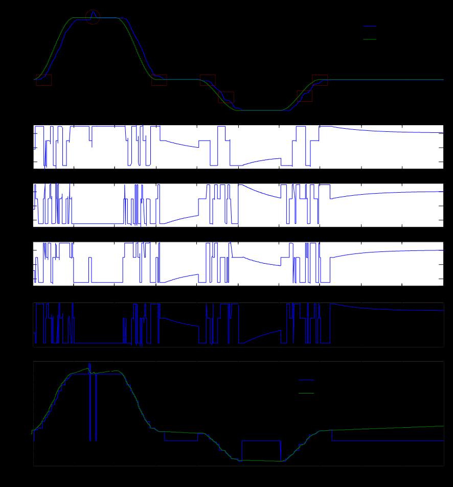
13 Simulation results 13
14 Energy Loss [W] [mm] Energy efficiency i sv i sv 1V2 1V1 1V2 1V A A 1 A 1 A 1 A 1 Current 1 HybridConcept 2 HybridConcept DigitalConcept A 2 2V2 2V1 A 1 A 1 2V2 2V1 Tank Lines p s1 p s2 1 % 71 1V 2PD % 67 % 19 % p s V 1PA 1V 2PA 1V 3PA Time [s] A C A A A B A D p A p B p c p D 1V 1PB 1V 2PB 1V 1PC 1V 2PC 1V 1PD 1V 3PB 1V 3PC 1V 3PD 14
15 Conclusions It is possible to control a system using a combination of areas and pressures that does not provide an equidistant distribution for the discrete forces values. The digital technical efficiency was proven superior to the current system considered and hybrid proposals from an energy savings point of view However, more research, is needed, especially in relation to control and fault tolerance, to allow the technique to be used in aircraft One suggestion to address this challenge is to evaluate the possibility of using a smaller control surface to control the small variations of load and use the digital actuator for greater demands situations. 15
16 Failure cases A C A A A B A D p A p B p c p D 1V 1PA 1V 1PB 1V 1PC 1V 1PD Rigth p s1 1V 2PA 1V 2PB 1V 2PC 1V 2PD p s2 1V 3PA 1V 3PB 1V 3PC 1V 3PD Tank Lines p s3 If a valve has one closed failure, the system would still be able to generate 54 discrete force values (3 3 x2 1 ), for each combination of pressure. If a valve has one open failure, which can be considered a failure in an actuator chamber, the system will operate with 27 discrete forces (3 3 ). If one pressure line fails, the number of discrete force will be reduced to 16 (2 4 ). 16
17 PhD researcher: Henri Carlo Belan, Cristiano C. Locateli, Advisor (SAAB): Birgitta Lantto, (LiU): Prof. Petter Krus, (UFSC): Prof. Victor J. De Negri,
12 - The Tie Set Method
 12 - The Tie Set Method Definitions: A tie set V is a set of components whose success results in system success, i.e. the presence of all components in any tie set connects the input to the output in the
AIRCRAFT BRAKING DYNAMICS AND BRAKE SYSTEM MODELING FOR FAULT DETECTION AND ISOLATION
 AIRCRAFT BRAKING DYNAMICS AND BRAKE SYSTEM MODELING FOR FAULT DETECTION AND ISOLATION Lucas Cardoso Navarro ITA São José dos Campos, São Paulo, Brazil Luiz Carlos Sandoval Goes ITA São José dos Campos,
ME 4232: FLUID POWER CONTROLS LAB. Class #5 Valve Modeling
 ME 4232: FLUID POWER CONTROLS LAB Class #5 Valve Modeling Notes No Office Hours Today Upcoming Labs: Lab 9: Flow Divider Lab 10: Sequencing Circuits 2 Agenda Wrap-up: Leakage Calculations Fluid Compressibility
Lecture 4. Lab this week: Cartridge valves Flow divider Properties of Hydraulic Fluids. Lab 8 Sequencing circuit Lab 9 Flow divider
 91 Lecture 4 Lab this week: Lab 8 Sequencing circuit Lab 9 Flow divider Cartridge valves Flow divider Properties of Hydraulic Fluids Viscosity friction and leakage Bulk modulus Inertance Cartridge Valves
Safety analysis on digital hydraulics Redundancy study for aviation applications
 Linköping University Division of Fluid and Mechatronic Systems Master Thesis Mechanical Engineering Spring 218 LIU-IEI-TEK-A--18/3195 SE Safety analysis on digital hydraulics Redundancy study for aviation
Reliability Analysis of Hydraulic Steering System with DICLFL Considering Shutdown Correlation Based on GO Methodology
 2015 ICRSE&PHM-Beijing Reliability Analysis of Hydraulic Steering System with DICLFL Considering Shutdown Correlation Based on GO Methodology YI Xiaojian, SHI Jian, MU Huina, DONG Haiping, GUO Shaowei
Lecture 5. Labs this week: Please review ME3281 Systems materials! Viscosity and pressure drop analysis Fluid Bulk modulus Fluid Inertance
 Labs this week: Lab 10: Sequencing circuit Lecture 5 Lab 11/12: Asynchronous/Synchronous and Parallel/Tandem Operations Please review ME3281 Systems materials! 132 Viscosity and pressure drop analysis
Experimental Verification of Fault Predictions in High Pressure Hydraulic Systems
 Modern Mechanical Engineering, 204, 4, 67-8 Published Online May 204 in SciRes. http://www.scirp.org/journal/mme http://dx.doi.org/0.426/mme.204.42008 Experimental Verification of Fault Predictions in
PUMP MODE PREDICTION FOR FOUR-QUADRANT VELOCITY CONTROL OF VALUELESS HYDRAULIC ACTUATORS
 Proceedings of the 7th JFPS International Symposium on Fluid Power, TOYAMA 2008 September 15-18, 2008 P1-13 PUMP MODE PREDICTION FOR FOUR-QUADRANT VELOCITY CONTROL OF VALUELESS HYDRAULIC ACTUATORS Christopher
REE 307 Fluid Mechanics II. Lecture 1. Sep 27, Dr./ Ahmed Mohamed Nagib Elmekawy. Zewail City for Science and Technology
 REE 307 Fluid Mechanics II Lecture 1 Sep 27, 2017 Dr./ Ahmed Mohamed Nagib Elmekawy Zewail City for Science and Technology Course Materials drahmednagib.com 2 COURSE OUTLINE Fundamental of Flow in pipes
Applied Fluid Mechanics
 Applied Fluid Mechanics 1. The Nature of Fluid and the Study of Fluid Mechanics 2. Viscosity of Fluid 3. Pressure Measurement 4. Forces Due to Static Fluid 5. Buoyancy and Stability 6. Flow of Fluid and
Dynamic Characteristic and Power Consumption on an Electro-Pneumatic Hybrid Positioning System
 2B2-4 Proceedings of the 6th JFPS International Symposium on Fluid Power, TSUKUBA 2005 November 7-10, 2005 Dynamic Characteristic and Power Consumption on an Electro-Pneumatic Hybrid Positioning System
Lecture 5. Labs this week:
 Labs this week: Lab 10: Bleed-off Circuit Lecture 5 Lab 11/12: Asynchronous/Synchronous and Parallel/Tandem Operations Systems Review Homework (due 10/11) Participation is research lab Hydraulic Hybrid
RESEARCH ON AIRBORNE INTELLIGENT HYDRAULIC PUMP SYSTEM
 8 TH INTERNATIONAL CONGRESS OF THE AERONAUTICAL SCIENCES RESEARCH ON AIRBORNE INTELLIGENT HYDRAULIC PUMP SYSTEM Jungong Ma, Xiaoye Qi, Juan Chen BeiHang University,Beijing,China jgma@buaa.edu.cn;qixiaoye@buaa.edu.cn;sunchenjuan@hotmail.com
Reliability of fluid systems
 EPJ Web of Conferences 114, 02057 (2016) DOI: 10.1051/ epjconf/ 2016114 02057 C Owned by the authors, published by EDP Sciences, 2016 Reliability of fluid systems Jaroslav Kopáek 1, Kamil Fojtášek 1,a
Chapter 18 Section 8.5 Fault Trees Analysis (FTA) Don t get caught out on a limb of your fault tree.
 Don t get caught out on a limb of your fault tree.") Chapter 18 Section 8.5 Fault Trees Analysis (FTA) Don t get caught out on a limb of your fault tree. C. Ebeling, Intro to Reliability & Maintainability Engineering, 2 nd ed. Waveland Press, Inc. Copyright
Chapter 18 Section 8.5 Fault Trees Analysis (FTA) Don t get caught out on a limb of your fault tree. C. Ebeling, Intro to Reliability & Maintainability Engineering, 2 nd ed. Waveland Press, Inc. Copyright
Description Quantity Opening Weight Max Rating 01/4721 Hydraulic Grip supplied with no faces, Single actuator, 15mm Pair Face 15Kg 60kN 315 bar
 A Hydraulic grip with single actuator, single actuator grips have one side adjusted by manual tightening action screw and the grips are suitable for offset sample alignment for shear testing Ideal for
Introduction to Atmospheric Flight. Dr. Guven Aerospace Engineer (P.hD)
") Introduction to Atmospheric Flight Dr. Guven Aerospace Engineer (P.hD) What is Atmospheric Flight? There are many different ways in which Aerospace engineering is associated with atmospheric flight concepts.
Introduction to Atmospheric Flight Dr. Guven Aerospace Engineer (P.hD) What is Atmospheric Flight? There are many different ways in which Aerospace engineering is associated with atmospheric flight concepts.
COMPARISON OF TWO METHODS TO SOLVE PRESSURES IN SMALL VOLUMES IN REAL-TIME SIMULATION OF A MOBILE DIRECTIONAL CONTROL VALVE
 COMPARISON OF TWO METHODS TO SOLVE PRESSURES IN SMALL VOLUMES IN REAL-TIME SIMULATION OF A MOBILE DIRECTIONAL CONTROL VALVE Rafael ÅMAN*, Heikki HANDROOS*, Pasi KORKEALAAKSO** and Asko ROUVINEN** * Laboratory
Water Circuit Lab. The pressure drop along a straight pipe segment can be calculated using the following set of equations:
 Water Circuit Lab When a fluid flows in a conduit, there is friction between the flowing fluid and the pipe walls. The result of this friction is a net loss of energy in the flowing fluid. The fluid pressure
Sensitivity of Wavelet-Based Internal Leakage Detection to Fluid Bulk Modulus in Hydraulic Actuators
 Proceedings of the nd International Conference of Control, Dynamic Systems, and Robotics Ottawa, Ontario, Canada, May 7 8, 15 Paper No. 181 Sensitivity of Wavelet-Based Internal Leakage Detection to Fluid
WORK SHEET FOR MEP311
 EXPERIMENT II-1A STUDY OF PRESSURE DISTRIBUTIONS IN LUBRICATING OIL FILMS USING MICHELL TILTING PAD APPARATUS OBJECTIVE To study generation of pressure profile along and across the thick fluid film (converging,
PTB S 16.5 MN HYDRAULIC AMPLIFICATION MACHINE AFTER MODERNIZATION
 IMEKO 22 nd TC3, 15 th TC5 and 3 rd TC22 International Conferences 3 to 5 February, 2014, Cape Town, Republic of South Africa PTB S 16.5 MN HYDRAULIC AMPLIFICATION MACHINE AFTER MODERNIZATION R. Kumme
E 094 E 103 E 143. Tank top mounting Connection up to G1 Nominal flow rate up to 135 l/min e
 R e t u r n F i l t e rs E 094 E 103 E 143 Tank top mounting Connection up to G1 Nominal flow rate up to 135 l/min 20.30-5e D e s c r i p t i o n Application In the return line circuits of hydraulic systems.
LECTURE 6- ENERGY LOSSES IN HYDRAULIC SYSTEMS SELF EVALUATION QUESTIONS AND ANSWERS
 LECTURE 6- ENERGY LOSSES IN HYDRAULIC SYSTEMS SELF EVALUATION QUESTIONS AND ANSWERS 1. What is the head loss ( in units of bars) across a 30mm wide open gate valve when oil ( SG=0.9) flow through at a
Rock Mechanics Laboratory Tests for Petroleum Applications. Rob Marsden Reservoir Geomechanics Advisor Gatwick
 Rock Mechanics Laboratory Tests for Petroleum Applications Rob Marsden Reservoir Geomechanics Advisor Gatwick Summary A wide range of well established and proven laboratory tests are available for petroleum
Exam #2: Fluid Kinematics and Conservation Laws April 13, 2016, 7:00 p.m. 8:40 p.m. in CE 118
 CVEN 311-501 (Socolofsky) Fluid Dynamics Exam #2: Fluid Kinematics and Conservation Laws April 13, 2016, 7:00 p.m. 8:40 p.m. in CE 118 Name: : UIN: : Instructions: Fill in your name and UIN in the space
LEAKLESS COOLING SYSTEM V.2 PRESSURE DROP CALCULATIONS AND ASSUMPTIONS
 CH-1211 Geneva 23 Switzerland EDMS No. ST/CV - Cooling of Electronics & Detectors GUIDE LEAKLESS COOLING SYSTEM V.2 PRESSURE DROP CALCULATIONS AND ASSUMPTIONS Objectives Guide to Leakless Cooling System
FLOW DIVIDERS "XV 3 serie" ENGLISH VERS:
 FLOW DIVIDERS "XV serie" ENGLISH VERS:07-0-01 0 VERS:0-0-008 XV-D FLOW DIVIDER XV-G FLOW DIVIDER + MOTOR This is the flow divider standard version, it simply divide the incoming flow without allowing the
CHAPTER 5 QUASI-STATIC TESTING OF LARGE-SCALE MR DAMPERS. To investigate the fundamental behavior of the 20-ton large-scale MR damper, a
 CHAPTER 5 QUASI-STATIC TESTING OF LARGE-SCALE MR DAMPERS To investigate the fundamental behavior of the 2-ton large-scale MR damper, a series of quasi-static experiments were conducted at the Structural
DSCC2012-MOVIC
 ASME 5th Annual Dynamic Systems and Control Conference joint with the JSME th Motion and Vibration Conference DSCC-MOVIC October 7-9,, Fort Lauderdale, Florida, USA DSCC-MOVIC-8784 DISPLACEMENT CONTROL
Hydraulic (Fluid) Systems
 Systems") Hydraulic (Fluid) Systems Basic Modeling Elements Resistance apacitance Inertance Pressure and Flow Sources Interconnection Relationships ompatibility Law ontinuity Law Derive Input/Output Models ME375
Hydraulic (Fluid) Systems Basic Modeling Elements Resistance apacitance Inertance Pressure and Flow Sources Interconnection Relationships ompatibility Law ontinuity Law Derive Input/Output Models ME375
NATIONAL CERTIFICATE (VOCATIONAL) APPLIED ENGINEERING TECHNOLOGY NQF LEVEL 4 NOVEMBER 2009
 APPLIED ENGINEERING TECHNOLOGY NQF LEVEL 4 NOVEMBER 2009") NATIONAL CERTIFICATE (VOCATIONAL) APPLIED ENGINEERING TECHNOLOGY NQF LEVEL 4 NOVEMBER 2009 (6021024) 30 October (Y-Paper) 13:00 16:00 A non-programmable scientific calculator may be used. This question
NATIONAL CERTIFICATE (VOCATIONAL) APPLIED ENGINEERING TECHNOLOGY NQF LEVEL 4 NOVEMBER 2009 (6021024) 30 October (Y-Paper) 13:00 16:00 A non-programmable scientific calculator may be used. This question
Matlab Sheet 2. Arrays
 Matlab Sheet 2 Arrays 1. a. Create the vector x having 50 logarithmically spaced values starting at 10 and ending at 1000. b. Create the vector x having 20 logarithmically spaced values starting at 10
CHAPTER 3 QUARTER AIRCRAFT MODELING
 30 CHAPTER 3 QUARTER AIRCRAFT MODELING 3.1 GENERAL In this chapter, the quarter aircraft model is developed and the dynamic equations are derived. The quarter aircraft model is two degrees of freedom model
D O T 1 ; O T 2 ; O T 3 ; O T i
 156 6 Fault diagnosis of pumps The model parameters O T h D O T 1 ; O T 2 ; O T 3 ; O T i 4 (6.1.38) were estimated by the leastsquares method in the form of discrete squareroot filtering (DSFI). Based
EXPERIMENT NO: F5. Losses in Piping Systems
 SJSU ME115 - THERMAL ENGINEERING LAB EXPERIMENT NO: F5 Losses in Piping Systems Objective One of the most common problems in fluid mechanics is the estimation of pressure loss. It is the objective of this
MODELING AND SIMULATION OF HYDRAULIC ACTUATOR WITH VISCOUS FRICTION
 MODELING AND SIMULATION OF HYDRAULIC ACTUATOR WITH VISCOUS FRICTION Jitendra Yadav 1, Dr. Geeta Agnihotri 1 Assistant professor, Mechanical Engineering Department, University of petroleum and energy studies,
Life Prediction of Aileron Actuator Using Finite Element Analysis
 Life Prediction of Aileron Actuator Using Finite Element Analysis Byeong-Sam Kim i, Kyoungwoo Park 2 Hyeon-Hee Kim 3 1 Department of Automotive Engineering, Hoseo University, Asan-City, 336-79,5 Korea
Chapter 1 Introduction
 Fundamentals of Thermodynamics Chapter 1 Introduction Prof. Siyoung Jeong Thermodynamics I MEE2022-01 Thermodynamics : Science of energy and entropy - Science of heat and work and properties related to
Load Prediction-based Energy-efficient Hydraulic Actuation. of a Robotic Arm. 1 Introduction
 oad rediction-based Energy-efficient Hydraulic ctuation of a Robotic rm Miss Can Du, rof ndrew lummer and Dr Nigel Johnston fixed displacement pump. This can reduce the weight of plant compared with the
Mechanics of Flight. Warren F. Phillips. John Wiley & Sons, Inc. Professor Mechanical and Aerospace Engineering Utah State University WILEY
 Mechanics of Flight Warren F. Phillips Professor Mechanical and Aerospace Engineering Utah State University WILEY John Wiley & Sons, Inc. CONTENTS Preface Acknowledgments xi xiii 1. Overview of Aerodynamics
FAULT DETECTION AND FAULT TOLERANT APPROACHES WITH AIRCRAFT APPLICATION. Andrés Marcos
 FAULT DETECTION AND FAULT TOLERANT APPROACHES WITH AIRCRAFT APPLICATION 2003 Louisiana Workshop on System Safety Andrés Marcos Dept. Aerospace Engineering and Mechanics, University of Minnesota 28 Feb,
Received 21 April 2008; accepted 6 January 2009
 Indian Journal of Engineering & Materials Sciences Vol. 16, February 2009, pp. 7-13 Inestigation on the characteristics of a new high frequency three-way proportional pressure reducing ale in ariable ale
Trajectory Planning, Setpoint Generation and Feedforward for Motion Systems
 2 Trajectory Planning, Setpoint Generation and Feedforward for Motion Systems Paul Lambrechts Digital Motion Control (4K4), 23 Faculty of Mechanical Engineering, Control Systems Technology Group /42 2
Electro-Hydrostatic Actuator (EHA) Position Tracking and Correction
 Position Tracking and Correction") Electro-Hydrostatic Actuator (EHA) Position Tracking and Correction i Electro-Hydrostatic Actuator (EHA) Position Tracking and Correction A Thesis Submitted to the School of Graduate Studies in Partial
Electro-Hydrostatic Actuator (EHA) Position Tracking and Correction i Electro-Hydrostatic Actuator (EHA) Position Tracking and Correction A Thesis Submitted to the School of Graduate Studies in Partial
Chapter 6. a. Open Circuit. Only if both resistors fail open-circuit, i.e. they are in parallel.
 Chapter 6 1. a. Section 6.1. b. Section 6.3, see also Section 6.2. c. Predictions based on most published sources of reliability data tend to underestimate the reliability that is achievable, given that
Mechanical Engineering Programme of Study
 Mechanical Engineering Programme of Study Fluid Mechanics Instructor: Marios M. Fyrillas Email: eng.fm@fit.ac.cy SOLVED EXAMPLES ON VISCOUS FLOW 1. Consider steady, laminar flow between two fixed parallel
Figure 3: Problem 7. (a) 0.9 m (b) 1.8 m (c) 2.7 m (d) 3.6 m
 0.9 m (b) 1.8 m (c) 2.7 m (d) 3.6 m") 1. For the manometer shown in figure 1, if the absolute pressure at point A is 1.013 10 5 Pa, the absolute pressure at point B is (ρ water =10 3 kg/m 3, ρ Hg =13.56 10 3 kg/m 3, ρ oil = 800kg/m 3 ): (a)
1. For the manometer shown in figure 1, if the absolute pressure at point A is 1.013 10 5 Pa, the absolute pressure at point B is (ρ water =10 3 kg/m 3, ρ Hg =13.56 10 3 kg/m 3, ρ oil = 800kg/m 3 ): (a)
INTERNATIONAL STANDARD
 INTERNATIONAL STANDARD ISO 8426 Second edition 2008-02-01 Hydraulic fluid power Positive displacement pumps and motors Determination of derived capacity Transmissions hydrauliques Pompes et moteurs volumétriques
Engineering Studies. Total marks 100
 2014 HIGHER SCHOOL CERTIFICATE EXAMINATION Engineering Studies General Instructions Reading time 5 minutes Working time 3 hours Write using black or blue pen Black pen is preferred Draw diagrams using
Risk Analysis of Highly-integrated Systems
 Risk Analysis of Highly-integrated Systems RA II: Methods (FTA, ETA) Fault Tree Analysis (FTA) Problem description It is not possible to analyse complicated, highly-reliable or novel systems as black box
Check-Q-meter. Table of contents. Features. Functions. RE 27551/ /10 Replaces: Type FD
 Check-Q-meter RE /0.0 /0 Replaces: 09.9 Type FD Nominal size... Series ax. Operating pressure 0 bar ax. Flow 0 l/min K9/ Table of contents Contents Page Features Functions Ordering details Symbols Functional
Index. Index. More information. in this web service Cambridge University Press
 A-type elements, 4 7, 18, 31, 168, 198, 202, 219, 220, 222, 225 A-type variables. See Across variable ac current, 172, 251 ac induction motor, 251 Acceleration rotational, 30 translational, 16 Accumulator,
FPMC PASSIVITY BASED BACKSTEPPING CONTROL FOR TRAJECTORY TRACKING USING A HYDRAULIC TRANSFORMER
 Proceedings of the ASME/BATH 25 Symposium on Fluid Power & Motion Control FPMC25 October 2-4, 25, Chicago, Illinois, United States FPMC25-968 PASSIVITY BASED BACKSTEPPING CONTROL FOR TRAJECTORY TRACKING
Rate of Flow Quantity of fluid passing through any section (area) per unit time
 per unit time") Kinematics of Fluid Flow Kinematics is the science which deals with study of motion of liquids without considering the forces causing the motion. Rate of Flow Quantity of fluid passing through any section
Kinematics of Fluid Flow Kinematics is the science which deals with study of motion of liquids without considering the forces causing the motion. Rate of Flow Quantity of fluid passing through any section
Rheometer: Procedure: Part A: Viscosity v Time
 Rheometer A fluid is defined as a substance that deforms continuously under the action of a shear stress, no matter how small the shear stress may be. Without shear stress, there will be no deformation.
Fault Detection and Diagnosis of an Electrohydrostatic Actuator Using a Novel Interacting Multiple Model Approach
 2011 American Control Conference on O'Farrell Street, San Francisco, CA, USA June 29 - July 01, 2011 Fault Detection and Diagnosis of an Electrohydrostatic Actuator Using a Novel Interacting Multiple Model
n = Kinematic viscosity (cst) SG = specific gravity or 1 Poise = 100 cp 1 Stoke = 100 cst Q = capacity (m 3 /s) A = tube area (m 2 ) or
 SG = specific gravity or 1 Poise = 100 cp 1 Stoke = 100 cst Q = capacity (m 3 /s) A = tube area (m 2 ) or") Fmulas Designation Fmula Comments Product Viscosity n = m r n = Kinematic viscosity (mm /s) m = Absolute viscosity (mpa.s) n = m SG n = Kinematic viscosity (cst) m = Absolute viscosity (cp) m = n SG 1
Fmulas Designation Fmula Comments Product Viscosity n = m r n = Kinematic viscosity (mm /s) m = Absolute viscosity (mpa.s) n = m SG n = Kinematic viscosity (cst) m = Absolute viscosity (cp) m = n SG 1
FLUID MECHANICS D203 SAE SOLUTIONS TUTORIAL 2 APPLICATIONS OF BERNOULLI SELF ASSESSMENT EXERCISE 1
 FLUID MECHANICS D203 SAE SOLUTIONS TUTORIAL 2 APPLICATIONS OF BERNOULLI SELF ASSESSMENT EXERCISE 1 1. A pipe 100 mm bore diameter carries oil of density 900 kg/m3 at a rate of 4 kg/s. The pipe reduces
Lecture Note 8-1 Hydraulic Systems. System Analysis Spring
 Lecture Note 8-1 Hydraulic Systems 1 Vehicle Model - Brake Model Brake Model Font Wheel Brake Pedal Vacuum Booster Master Cylinder Proportionnig Valve Vacuum Booster Rear Wheel Master Cylinder Proportioning
HARDWARE-IN-THE-LOOP SIMULATION EXPERIMENTS WITH A HYDRAULIC MANIPULATOR MODEL
 HARDWARE-IN-THE-LOOP SIMULATION EXPERIMENTS WITH A HYDRAULIC MANIPULATOR MODEL Jorge A. Ferreira, André F. Quintã, Carlos M. Cabral Departament of Mechanical Engineering University of Aveiro, Portugal
Hydraulic Fundamentals Hydraulics Definition Advent of Oil Hydraulics Pascal s Law Pressure
 Fluidsys Training Centre, Bangalore offers an extensive range of skill-based and industry-relevant courses in the field of Pneumatics and Hydraulics. For more details, please visit the website: https://fluidsys.org
Q1 Give answers to all of the following questions (5 marks each):
:") FLUID MECHANICS First Year Exam Solutions 03 Q Give answers to all of the following questions (5 marks each): (a) A cylinder of m in diameter is made with material of relative density 0.5. It is moored
FLUID MECHANICS First Year Exam Solutions 03 Q Give answers to all of the following questions (5 marks each): (a) A cylinder of m in diameter is made with material of relative density 0.5. It is moored
Failure Prognostics with Missing Data Using Extended Kalman Filter
 Failure Prognostics with Missing Data Using Extended Kalman Filter Wlamir Olivares Loesch Vianna 1, and Takashi Yoneyama 2 1 EMBRAER S.A., São José dos Campos, São Paulo, 12227 901, Brazil wlamir.vianna@embraer.com.br
DYNAMICS OF PNEUMATIC CYLINDER SYSTEMS
 DYNAMICS OF PNEUMATIC CYLINDER SYSTEMS Toshinori FUJITA*, Jiseong JANG*, Toshiharu KAGAWA* and Masaaki TAKEUCHI** *Department of Control & Systems Engineering, Faculty of Engineering Tokyo Institute of
PUMP MODE PREDICTION FOR FOUR-QUADRANT VELOCITY CONTROL OF VALVELESS HYDRAULIC ACTUATORS
 P1-13 Proceedings of the 7th JFPS International Symposium on Fluid Power, TOYM 28 September 15-18, 28 PUMP MODE PREDICTION FOR FOUR-QUDRNT VELOCITY CONTROL OF VLVELESS HYDRULIC CTUTORS Christopher WILLIMSON,
An-Najah National University Civil Engineering Department. Fluid Mechanics. Chapter 1. General Introduction
 1 An-Najah National University Civil Engineering Department Fluid Mechanics Chapter 1 General Introduction 2 What is Fluid Mechanics? Mechanics deals with the behavior of both stationary and moving bodies
Virtual Work & Energy Methods. External Energy-Work Transformation
 External Energy-Work Transformation Virtual Work Many structural problems are statically determinate (support reactions & internal forces can be found by simple statics) Other methods are required when
Exp All technology at operator s service. Suggested Orange peel. Straight boom m. Industrial straight stick 8.00 m RV 600 2,
 Exp 5055 Exp 5055 All technology at operator s service 0 1 2 3 4 5 6 7 8 9 10 11 12 13 14 15 16 17 18 19 20 0 1 2 3 4 5 6 7 8 9 10 11 12 13 14 15 16 17 18 19 20 20 19 18 17 16 15 14 13 12 11 10 8 9 7 6
SYSTEM ANALYSIS AND ISOTHERMAL SEPARATE EFFECT EXPERIMENTS OF THE ACCIDENT BEHAVIOR IN PWR SPENT FUEL STORAGE POOLS
 SYSTEM ANALYSIS AND ISOTHERMAL SEPARATE EFFECT EXPERIMENTS OF THE ACCIDENT BEHAVIOR IN PWR SPENT FUEL STORAGE POOLS H. Chahi 1, W. Kästner 1 and S. Alt 1 1 : University of Applied Sciences Zittau/GörlitzInstitute
Thermal analysis of hydraulic system of landing gear
 IOP Conference Series: Materials Science and Engineering PAPER OPEN ACCESS Thermal analysis of hydraulic system of landing gear To cite this article: S Badrinarayanan et al 2018 IOP Conf. Ser.: Mater.
THEORETIC AND EXPERIMENTAL RESEARCH ON THE CHARACTERISTIC DIAGRAMS OF A NEW TYPE OF ROTATING MACHINE WITH PROFILED ROTORS
 U.P.B. Sci. Bull., Series D Vol. 74, Iss. 3, 2012 ISSN 1454-2358 THEORETIC AND EXPERIMENTAL RESEARCH ON THE CHARACTERISTIC DIAGRAMS OF A NEW TYPE OF ROTATING MACHINE WITH PROFILED ROTORS Alin Ovidiu MOTORGA
A 954 C HD. Technical Description Hydraulic Excavator. Machine for Industrial Applications
 Technical Description Hydraulic Excavator A 95 C HD litronic` Machine for Industrial Applications Operating Weight 165,800 170,0 lb Engine Output 36 hp (0 kw) Technical Data Engine Rating per ISO 99 0
Return fi lters. MPI series. Maximum working pressure up to 1 MPa (10 bar) - Flow rate up to 3000 l/min
 - Flow rate up to 3000 l/min") Return fi lters series Maximum working pressure up to MPa (0 bar) Flow rate up to 000 l/min 0 Return fi lters Introduction FILTER SIZING INDEX CALCULATION CORRECTIVE FACTOR Page Introduction Calculation
Return fi lters series Maximum working pressure up to MPa (0 bar) Flow rate up to 000 l/min 0 Return fi lters Introduction FILTER SIZING INDEX CALCULATION CORRECTIVE FACTOR Page Introduction Calculation
spatial water demand (population density) spatial junctions distribution (building density) digital elevation map
 spatial junctions distribution (building density) digital elevation map") SYSTEM ID: WDS-Designer NARRATIVE DESCRIPTION With the WDS Designer a tool for the algorithmic generation of synthetic water distribution systems (swds) based on GIS data was presented (Sitzenfrei et al.,
SYSTEM ID: WDS-Designer NARRATIVE DESCRIPTION With the WDS Designer a tool for the algorithmic generation of synthetic water distribution systems (swds) based on GIS data was presented (Sitzenfrei et al.,
Design of Restricted Orifice Surge Tank
 Design of Restricted Orifice Surge Tank August 3, 13 Contents 1. Necessity of Surge Tank 1. Requirements for Hydraulic Design of Restricted Orifice Surge Tank 1 3. Fundamental Differential Equations 1
Research Article Study on the Dynamics of Local Pressure Boosting Pneumatic System
 Mathematical Problems in Engineering Volume 215 Article ID 84947 11 pages http://dx.doi.org/1.1155/215/84947 Research Article Study on the Dynamics of Local Pressure Boosting Pneumatic System Yan Shi Guanwei
Safety analysis and standards Analyse de sécurité et normes Sicherheitsanalyse und Normen
 Industrial Automation Automation Industrielle Industrielle Automation 9.6 Safety analysis and standards Analyse de sécurité et normes Sicherheitsanalyse und Normen Prof Dr. Hubert Kirrmann & Dr. B. Eschermann
Integrated analysis of hydraulic PTOs in WECs
 Integrated analysis of hydraulic PTOs in WECs Conference on CeSOS Highlights and AMOS Visions Limin Yang 29 th May, 2013, Trondheim Content Introduction Model description of wave energy converter (WEC)
SVH with HYDROVAR (HVL range)
") SVH with HYDROVAR (HVL range) SVH-HVL Rev. B Ed.9/1 (EN) SVH SERIES (e-sv WITH HYDROVAR) Background and context For all pumping needs in commercial or residential building and in industry applications,
SVH with HYDROVAR (HVL range) SVH-HVL Rev. B Ed.9/1 (EN) SVH SERIES (e-sv WITH HYDROVAR) Background and context For all pumping needs in commercial or residential building and in industry applications,
Modelling the Dynamics of Flight Control Surfaces Under Actuation Compliances and Losses
 Modelling the Dynamics of Flight Control Surfaces Under Actuation Compliances and Losses Ashok Joshi Department of Aerospace Engineering Indian Institute of Technology, Bombay Powai, Mumbai, 4 76, India
WATER DISTRIBUTION NETWORKS
 WATER DISTRIBUTION NETWORKS CE 370 1 Components of Water Supply System 2 1 Water Distribution System Water distribution systems are designed to adequately satisfy the water requirements for a combinations
DIN 2445 Part-2 SEAMLESS STEEL TUBES FOR DYNAMIC LOADS SUPPLEMENT BASIS FOR CALUCULATION OF STRAIGHT TUBES
 DIN Part- SEAMLESS STEEL TUBES FOR DYNAMIC LOADS SUPPLEMENT BASIS FOR CALUCULATION OF STRAIGHT TUBES. General information During the operation of hydraulic installations, when the control valve is operated
I n t h e a i r, o n l a n d,
 I n t h e a i r, o n l a n d, a n d u n d e r t h e s e a. W e a r e p a s s i o n a t e a b o u t o u r h y d r a u l i c s. L e t u s s u r p r i s e y o u! During its fifty years of experience in the
DESIGN PROJECT REPORT: Longitudinal and lateral-directional stability augmentation of Boeing 747 for cruise flight condition.
 DESIGN PROJECT REPORT: Longitudinal and lateral-directional stability augmentation of Boeing 747 for cruise flight condition. Prepared By: Kushal Shah Advisor: Professor John Hodgkinson Graduate Advisor:
PROBABILISTIC AND POSSIBILISTIC FAULT TREE ANALYSIS
 PROBABILISTIC AD POSSIBILISTIC FAULT TREE AALYSIS M. Ragheb 12/28/2017 ITRODUCTIO In the design of nuclear power plants, it is important to analyze the probable and possible mechanisms of failure. Fault
ENERGY CONVERSION IN A FLUID POWER SYSTEM. Preview GRC. mechanical friction. File name GA: FLOW GENERATING GROUP. traen_eng GRC: CONTROL GROUP
 PRIME MOVER (electric motor, IC engine) ENERGY CONVERSION IN FLUID POWER SYSTEM P P mech mech (exended) P P (useful) hydr hydr rotary shaft G M, Q, Q, M, F, v P W GRC P W GU oil ies oil ies rotary shafts,
Hydraulics. B.E. (Civil), Year/Part: II/II. Tutorial solutions: Pipe flow. Tutorial 1
, Year/Part: II/II. Tutorial solutions: Pipe flow. Tutorial 1") Hydraulics B.E. (Civil), Year/Part: II/II Tutorial solutions: Pipe flow Tutorial 1 -by Dr. K.N. Dulal Laminar flow 1. A pipe 200mm in diameter and 20km long conveys oil of density 900 kg/m 3 and viscosity
Hydraulics B.E. (Civil), Year/Part: II/II Tutorial solutions: Pipe flow Tutorial 1 -by Dr. K.N. Dulal Laminar flow 1. A pipe 200mm in diameter and 20km long conveys oil of density 900 kg/m 3 and viscosity
LECTURE 8. Hydraulic machines and systems II 2002 MIT PSDAM LAB
 LECTURE 8 Hydraulic machines and systems II Basic hydraulic machines & components Graphical Nomenclature Arrows show direction of flow Control Volume Pipe or hose with fluid flow Pipe or hose without fluid
Modeling, Control and Experimental Validation of a Device for Seismic Events Simulation
 Modeling, Control and Experimental Validation of a Device for Seismic Events Simulation Paolo Righettini, Roberto Strada, Vittorio Lorenzi, Alberto Oldani, Mattia Rossetti Abstract Single and multi-axis
2002 Prentice Hall, Inc. Gene F. Franklin, J. David Powell, Abbas Emami-Naeini Feedback Control of Dynamic Systems, 4e
 u Figure 2.1 Cruise-control model x Friction force bx m x u Figure 2.2 Free-body diagram for cruise control S P 278 Figure 2.3 Automobile suspension y m 2 k s b v car x m 1 k w Road surface r Inertial
Russell B. Schweickart and Gary Mills
 ANALYSIS AND TEST VERIFICATION OF TRANSITIONAL FLOW IN A DEWAR VENT Russell B. Schweickart and Gary Mills Ball Aerospace & Technologies Corp. Boulder, CO 80301 USA ABSTRACT The pressure of the cryogen
SAMPLE CANISTER CAPTURE MECHANISM FOR MSR: CONCEPT DESIGN AND TESTING RESULTS INCLUDING 0-G ENVIRONMENT
 SAMPLE CANISTER CAPTURE MECHANISM FOR MSR: CONCEPT DESIGN AND TESTING RESULTS INCLUDING 0-G ENVIRONMENT Authors: Riccardo Carta, Daniele Filippetto, Politecnico di Milano Co-authors: Prof. Michèle Lavagna,
Why fault tolerant system?
 Why fault tolerant system? Non Fault-Tolerant System Component 1 Component 2 Component N The reliability block diagram of a series systemeach element of the system must operate correctly for the system
1/54 Circulation pump, safety valve, expansion vessel
 1/54 Circulation pump, safety valve, expansion vessel pressure loss efficiency of pump secured heat output safety valve sizing expansion vessel sizing Circulation pump 2/54 similar principle as for heating
Laboratory work No 2: Calibration of Orifice Flow Meter
 Laboratory work No : Calibration of Orifice Flow Meter 1. Objective Calibrate the orifice flow meter and draw the graphs p = f 1 (Q) and C d = f (Re ).. Necessary equipment 1. Orifice flow meter. Measuring
Displacement Control Strategies of an In-Line Axial-Piston Unit
 The 5th Scandinavian International Conference on Fluid Power, SICFP 7, June 7-9, 27, Displacement Control Strategies of an In-Line Axial-Piston Unit L. Viktor Larsson and Petter Krus Division of Fluid
PERFORMANCE OF A CENTRAL-TYPE JET PUMP II- EXPERIMENTAL STUDY ON WATER FLOW
 Eighth International Water Technology Conference, IWTC8 24, Alexandria, Egypt PERFORMANCE OF A CENTRAL-TYPE JET PUMP II- EXPERIMENTAL STUDY ON WATER FLOW ABSTRACT EL-Otla, F. M. *, EL-Sawaf, I. A. * and
Modeling and Simulation for Automatic Control
 Modeling and Simulation for Automatic Control Olav Egeland and Jan Tommy Gravdahl Norwegian University of Science and Technology Trondheim, Norway MARINE CYBERNETICS Г~Т.! " " http://www.mannecybemetics.com