Improving Motor Efficiency and Motor Miniaturisation The Role of Thermal Simulation. Dr David Staton Motor Design Ltd
|
|
|
- Marcia Wilson
- 6 years ago
- Views:
Transcription
1 Improving Motor Efficiency and Motor Miniaturisation The Role of Thermal Simulation Dr David Staton Motor Design Ltd
2 Motor Design Ltd (MDL) Todays Topics Need for improved tools for thermal analysis of electric machines Important Issues in Thermal Analysis of Electric Motors Examples of use of thermal analysis to optimise electric machine designs
 Gyula Vainel (Motor Design Engineer) Lyndon Evans (Software Development) James Goss (EngD Motor-LAB) Lilo Bluhm (Office Manager) Many University")
3 Motor Design Ltd Based in Ellesmere, Shropshire, UK On England/Wales border South of Chester and Liverpool MDL Team: Dave Staton (Software Development & Consultancy) Mircea Popescu (Consultancy) Douglas Hawkins (Software Development & Consultancy) Gyula Vainel (Motor Design Engineer) Lyndon Evans (Software Development) James Goss (EngD Motor-LAB) Lilo Bluhm (Office Manager) Many University Links: Sponsor 3 Students in UK at present Many links with universities throughout world Bristol, City, Edinburgh, Mondragon Sheffield, Torino,
4 Dave Staton Apprentice/Electrician - Coal Mining Industry ( ) BSc in Electrical Engineering at Trent Polytechnic (Nottingham) PhD at University of Sheffield ( ) CAD of Permanent Magnet DC Motors (with GEC small machines) 95% electromagnetic aspects and less than 5% on thermal aspects Design Engineer - Thorn-EMI CRL ( ) design of electric motors for Kenwood range of food processors Research Fellow - SPEED Laboratories ( ) help develop SPEED electric motor design software predominantly on electromagnetic aspects Control Techniques (part of Emerson Electric) ( ) design of servo motors More involved in thermal analysis as we were developing radically new motor constructions (segmented laminations) that we had no previous experience. Set up Motor Design Ltd in 1998 to develop heat transfer software for electric machine simulation there was no commercial software for thermal analysis of motors such analysis was becoming more important in the design process (volume/weight minimisation, energy efficiency, etc.) Given many courses on motor design and thermal analysis of electric machines worldwide
5 Motor Design Ltd (MDL) set up in 1998 to develop software for design of electric motors and provide motor design consulting and training distribute SPEED, Motor-CAD, FLUX and PORTUNUS software complete package for electric motor and drive simulation software package also used in our consulting work which helps with development
6 Motor Design Ltd (MDL) Todays Topics Need for improved tools for thermal analysis of electric machines Important Issues in Thermal Analysis of Electric Motors Examples of use of thermal analysis to optimise electric machine designs
7 Thermal and Electromagnetic Design Traditionally in electric motors design the thermal design has received much less attention than the electromagnetic design electric motor designers tend to have an electrical engineering background rather than mechanical? CAD tools for thermal design have tended to be very specialized and require extensive knowledge of heat transfer MDL have developed Motor-CAD + Portunus thermal/flow library to make it easier to carry out thermal analysis without being a thermal expert FEA and CFD software are starting to have features included to make it easier to set up electric motor thermal models There is a similar situation in electronics cooling Electronics designers tend to have an electronics background with little knowledge of heat transfer
8 Need for thermal analysis of electric motors 1M Ave. expected life [hours] 100 K 10K 1K Class A Class B Class F Class H Total winding temp. [deg C] Temperature of motor is ultimate limit on performance and should be given equal importance to the electromagnetic design Life of motor is dependent upon the winding temperature
9 Need for thermal analysis of electric motors There is a requirement for smaller, cheaper and more efficient motors so an optimised design is required Losses depend on temperature and temperature on losses Simple sizing method based on such inputs as limiting winding current density are no good for optimisation (see next few slides) depend on users experience for the manufacturing process and material used and so tend to become very inaccurate when trying something new in the design Give the designer no indication of where to concentrate design effort to reduce temperature Mix of analytical and numerical methods required Many applications do not have a steady-state operation so in order to obtain a reasonable transient calculation time lumped circuit techniques are required CFD/FEA are useful to help set up accurate models Part models best. e.g. heat transfer through winding, fan model, etc.
10 Traditional Motor Sizing Methods sizing based on single parameter thermal resistance housing heat transfer coefficient winding current density specific electric loading thermal data from simple rules of thumb 5 A/mm2, 12 W/m2/C etc. tests on existing motors competitor catalogue data can be inaccurate single parameter fails to describe complex nature of motor cooling poor insight of where to concentrate design effort Alternatives are analytical lumped circuit thermal analysis and numerical thermal analysis T winding Thermal Resistance R TH [ o C/W] P [W] T ambient Heat Transfer Coefficient h [W/(m 2. o C)]
 Air Forced Convection h =10-300 W/(m 2.C) Liquid Forced Convection h = 50-20000 W/(m 2.")

11 Typical Rules of Thumb Air Natural Convection h = 5-10 W/(m 2.C) Air Forced Convection h = W/(m 2.C) Liquid Forced Convection h = W/(m 2.C) Wide range of possible values makes past experience very important Otherwise the design will not be correctly sized Values may not be valid if change manufacturing process, material, etc. Tables taken from: SPEED Electric Motors, TJE Miller
 Useful to accurately calculate conduction heat transfer Computational fluid dynamics (CFD)")
 Many of the Fluent CFD slides are from the Example from University of")
12 Numerical Thermal Analysis Two basic types available that subdivide problem into small element or volumes and temp/flow solved: Finite element analysis (FEA) Useful to accurately calculate conduction heat transfer Computational fluid dynamics (CFD) Simulation of fluid flow involves the solution of a set of coupled, nonlinear, second order, partial differential equations conservation equations (velocity, pressure & temperature) Many of the Fluent CFD slides are from the Example from University of Nottingham CFD FEA
13 Motor-CAD Integrated Thermal FEA Solver Just a few seconds to generate a mesh and calculate Help improve accuracy through calibration of analytical model


14 Computational Fluid Dynamics (CFD) The expected accuracy is not as great as with electromagnetic FEA Due to complexities of geometry and turbulent fluid flow Impossible to model actual geometry perfectly But trend predictions and visualisation of flow are useful Can be very time consuming to construct a model and then calculate Can be several weeks/months Best use of results to calibrate analytical formulations


15 Motor-CAD Software Analytical network analysis package dedicated to thermal analysis of electric motors and generators input geometry using dedicated editors select cooling type, materials, etc and calculate steady state or transient temperatures all difficult heat transfer data calculated automatically easy to use by non heat transfer specialists provides a detailed understanding of cooling and facilitates optimisation what-if & sensitivity analysis


16 Motor-CAD Motor Types Brushless Permanent Magnet Inner and outer rotor Induction/Asynchronous 1 and 3 phase Switched reluctance Permanent magnet DC Wound Field Synchronous Claw pole
 many housing design types")


17 Cooling Types Motor-CAD includes proven models for an extensive range of cooling types Natural Convection (TENV) many housing design types Forced Convection (TEFC) many fin channel design types Through Ventilation rotor and stator cooling ducts Open end-shield cooling Water Jackets many design types (axial and circumferential ducts) stator and rotor water jackets Submersible cooling Wet Rotor & Wet Stator cooling Spray Cooling Direct conductor cooling Slot water jacket Conduction Internal conduction and the effects of mounting Radiation Internal and external


18 Housing Types Many housing designs can be modeled and optimized the designer selected a housing type that is appropriate for the cooling type to be used and then optimizes the dimensions, e.g. axial fin dimensions and spacing for a TEFC machine


19 Steady-State & Transient Analysis Some application are steady state and some operate with complex transient duty cycle loads
20 Thermal Lumped Circuit Models similar to electrical network so easy to understand by electrical engineers thermal resistances rather than electrical resistances power sources rather than current sources thermal capacitances rather than electrical capacitors (not shown here) nodal temperatures rather than voltages power flow through resistances rather than current Place nodes at important places in motor cross-section
21 Thermal Lumped Circuit Models thermal resistances placed in the circuit to model heat transfer paths in the machine conduction (R = L/kA) path area (A) and length (L) from geometry thermal conductivity (k) of material convection (R = 1/hA) heat transfer coefficient (h W/m 2.C) from empirical dimensionless analysis formulations (correlations) many well proven correlations for all kinds of geometry in heat transfer technical literature radiation (R = 1/hA) h = σ ε 1 F 1-2 (T 1 4 T 24 )/ (T 1 T 2 ) emissivity (ε 1 ) & view factor (F 1-2 ) from surface finish & geometry power input at nodes where losses occur thermal capacitances for transient analysis Capacitance = Weight Specific Heat Capacity
22 Heat Transfer Ohms Law: In a thermal network the heat flow is given by: T P = electrical circuit I = R P = power [Watts] T = temperature difference [C] R = thermal resistance [C/W] P V R T R Fluid Temperature Rise: Power Dissipated T = Volume Flow Rate x Density x C p T = temperature difference [C] C p = Specific Heat Capacity [J/kg C]
23 Motor Design Ltd (MDL) Todays Topics Need for improved tools for thermal analysis of electric machines Important Issues in Thermal Analysis of Electric Motors Examples of use of thermal analysis to optimise electric machine designs
24 Important Issues in Thermal Analysis of Electric Motors Conduction, Convection and Radiation Losses Winding Heat Transfer Interface Thermal Resistance Accuracy and Calibration
25 Conduction Heat Transfer Heat transfer mode in a solid due to molecule vibration Good electrical conductors are also good thermal conductors Would like good electrical insulators that are good thermal conductors material research to try to achieve this Metals have large thermal conductivities due to their well ordered crystalline structure k is usually in the range of W/m/C Solid insulators not well ordered crystalline structure and are often porous k is typically in the range of 0.1 1W/m/C (better than air with k 0.026W/m/C) Conduction thermal resistance calculated using R = L/kA Path length (L) and area (A) from geometry, e.g. tooth width and area Thermal conductivity (k) of material, e.g. that of electrical steel for tooth Only complexity is in the calculation of effective L, A and k for composite components such as winding, bearings, etc. Motor-CAD benefits from research using numerical analysis and testing to develop reliable models for such complicated components
26 Convection Heat Transfer Heat transfer mode between a surface and a fluid due to intermingling of the fluid immediately adjacent to the surface (conduction here) with the remainder of the fluid due to fluid motion Natural Convection fluid motion due to buoyancy forces arising from change in density of fluid in vicinity of the surface Forced Convection fluid motion due to external force (fan and pump) Two types of flow Laminar Flow, streamlined flow at lower velocities Turbulent Flow, eddies at higher velocities Enhanced heat transfer compared to laminar flow but a larger pressure drop Convection thermal resistance is calculated using: A = surface area [m 2 ] R C = 1/ (A h) [C/W] h = convection heat transfer coefficient [W/m 2 /C] Need to predict h rule thumb, dimensionless analysis, CFD?
27 Convection Heat Transfer Coefficient h C can be calculated using empirical correlations based on dimensionless numbers (Re, Gr, Pr, Nu) Just find a correlation with a similar geometry and cooling type to that being studied Cylinder, flat plate, open/enclosed channel, etc. Dimensionless numbers allow the same formulation to be used with different fluids and dimensions to those used in the original experiments Hundreds of correlations available in the technical literature allowing engineers to carry out the thermal analysis of almost any shape of apparatus Motor-CAD automatically selects the most appropriate correlation that matches the cooling type and surface shape
28 Convection Analysis Dimensionless Numbers Reynolds number (R e ) Grashof number (G r ) h = heat transfer coefficient [W/m 2 C] µ = fluid dynamic viscosity [kg/s m] ρ = fluid density [kg/m 3 ] k = thermal conductivity of the fluid [W/mC] c p = specific heat capacity of the fluid [kj/kg.c] Prandtl number (P r ) Nusselt number (N u ) R e = ρ v L / µ G r = β g θ ρ 2 L 3 / µ 2 P r = c p µ / k N u = h L / k v = fluid velocity [m/s] θ = surface to fluid temperature [C] L = characteristic length of the surface [m] β = coefficient of cubical expansion of fluid [1/C] g = acceleration due to gravity [m/s2] The dimensionless numbers are functions of fluid properties, size (characteristic length), fluid velocity (forced convection), temperature (natural convection) and gravity (natural convection)
29 Natural and Forced Convection Correlations Natural convection is present over most surfaces Present even over surfaces that are designed for forced convection e.g. TEFC machine with axial fins (at low speed the fan will not provide much forced air and natural convection will dominate) Large set of correlations typically required for complex shapes For very complex shapes area averaged composite correlations are used where the complex geometry (e.g. finned housing) is divided into a set of simpler shapes for which convection correlations are known For instance a cylinder with axial fins is divided to various cylindrical and open fin channel sections of different orientation A positive aspect is that if extremely small fins are attached to the cylinder the same results are given as for a cylindrical correlation Forced convection is present over surfaces with fluid movement due to a fan or pump (or movement of the device or wind) A more limited set of correlations are required to calculate forced convection in electrical machines (Flat Plate, Open Fin Channel, Enclosed Channel, Rotating Airgap, End Space Cooling)
30 General Form for Convection Correlations Natural Convection General form of natural convection correlation : N u = a (G r P r ) b a & b are curve fitting constants Transition from laminar to turbulent flow: 107 < GrPr < 109 (GrPr = Ra Rayleigh number) Forced Convection General form of convection correlation for forced convection: Nu = a (Re) b (Pr) c a, b & c are curve fitting constants Internal flow laminar/turbulent transition R e 2300 (fully turbulent R e > 5 x 10 4 ) External flow laminar/turbulent transition R e 5 x 10 5
31 Horizontal Cylinder (Natural Convection) A formulation for average Nusselt number of a horizontal cylinder of diameter d: N u = (G r P r ) 0.25 (10 4 < G r P r < 10 9 ) Laminar N u = (G r P r ) 0.33 h = N u k / d (10 9 < G r P r < ) Turbulent Fluid properties at mean film temperature (average of surface and bulk fluid temperatures)
 Laminar N u = 0.129 (G r P r ) 0.")
32 Vertical Cylinder (Natural Convection) A formulation for average Nusselt number of a vertical cylinder of height L: N u = 0.59 (G r P r ) 0.25 (10 4 < G r P r < 10 9 ) Laminar N u = (G r P r ) 0.33 (10 9 < G r P r < ) Turbulent h = N u k / L Fluid properties at mean film temperature (average of surface and bulk fluid temperatures)
 Laminar N u = 0.129 (G r P r ) 0.")
33 Vertical Flat Plate (Nat Convection) A formulation for average Nusselt number of a vertical flat plate of height L: N u = 0.59 (G r P r ) 0.25 (10 4 < G r P r < 10 9 ) Laminar N u = (G r P r ) 0.33 (10 9 < G r P r < ) Turbulent h = N u k / L fluid properties at mean film temperature (average of surface and bulk fluid temperatures)
 Turbulent N u = 0.25 (G r P r ) 0.")
34 Horizontal Flat Plate (Nat Conv) Upper Face: N u = 0.54 (G r P r ) 0.25 (10 5 < G r P r < 10 8 ) Laminar upper N u = 0.14 (G r P r ) 0.33 Lower Face: (10 8 < G r P r ) Turbulent N u = 0.25 (G r P r ) 0.25 (10 5 < G r P r < 10 8 ) Laminar lower h = N u k / L Fluid properties at mean film temperature (average of surface and bulk fluid temperatures)

![[%]/100} As corner cut-out approaches 100% then the cylinder correlation](/docs-images/79/80126721/images/35-2.jpg "predominates and as it approaches 0% the tube correlation predominates")
35 Horizontal Servo Housing (Nat Conv) Average of the following: Horizontal Cylinder Corner Cutout [%]/100 Horizontal Square Tube {1 - Corner Cutout [%]/100} As corner cut-out approaches 100% then the cylinder correlation predominates and as it approaches 0% the tube correlation predominates
![Vertical Fin Channel (N Conv) Ref [1] gives a formulation for Nusselt number of u-shaped vertical channels (laminar flow): r 0.75 GP L r r L 0.5 Nu = 1 exp Z Z r GP r r 1 0.](/docs-images/79/80126721/images/36-0.jpg "483 exp( 0.17 ) a Z = 24 3 3 3 1 ( 1 exp( 0.83a) ) 9.14 a + 1 a + 2 exp( 465 fin_spacing ) 0.")
. [1] Van De Pol, D.W.")
36 Vertical Fin Channel (N Conv) Ref [1] gives a formulation for Nusselt number of u-shaped vertical channels (laminar flow): r 0.75 GP L r r L 0.5 Nu = 1 exp Z Z r GP r r exp( 0.17 ) a Z = ( 1 exp( 0.83a) ) 9.14 a + 1 a + 2 exp( 465 fin_spacing ) 0.61 h = N u k / r a = channel aspect ratio fin_spacing/fin_depth r = Characteristic Length (fin hydraulic radius) = 2 fin_depth fin_spacing /(2 fin_depth + fin_spacing) L = fin height The fluid properties are evaluated at the wall temperature (except volumetric coefficient of expansion which is evaluated at the mean fluid temperature). [1] Van De Pol, D.W. & Tierney, J.K. : Free Convection Nusselt Number for Vertical U-Shaped Channels, Trans. ASME, Nov
![Horizontal Fin Channel (Nat Conv) Horizontal Fin Channels Ref [1] gives a formulation for Nusselt number of u-shaped horizontal channels (laminar flow): 0.44 7640 Nu( s) = 0.](/docs-images/79/80126721/images/37-0.jpg "00067 Gr( sp ) r( s) 1 exp Pr Gr ( s) h = N u (s) k / s s = fin spacing used as characteristic dimension 1.7 [1] Jones, C.D., Smith, L.F.")
37 Horizontal Fin Channel (Nat Conv) Horizontal Fin Channels Ref [1] gives a formulation for Nusselt number of u-shaped horizontal channels (laminar flow): Nu( s) = Gr( sp ) r( s) 1 exp Pr Gr ( s) h = N u (s) k / s s = fin spacing used as characteristic dimension 1.7 [1] Jones, C.D., Smith, L.F. : Optimum Arrangement of Rectangular Fins on Horizontal Surfaces for Free-Convection Heat Transfer, Trans. ASME, Feb 1970.

 see")
38 Axial Finned Housing with Natural Convection The axial finned motors above are designed for a shaft mounted fan (TEFC) When used as a variable speed drive at low speed there is little forced convection as natural convection dominates Therefore we must be able to calculate such surfaces with natural convection Use of composite calculations based on averages of all the different simple shapes found in the more complex shape can give accurate results Good agreement between Motor-CAD with default data and measured data for a range of TEFC motors operating at zero speed (work carried out by Boglietti at Politecnico di Torino) see graph above
39 Flat Plate flow Forced Conv (External Flow) Ref [1] gives a formulation for average Nusselt number of flat plate (or horizontal cylinder) length L: N u = (R e ) 0.5 (P r ) 0.33 (R e < 5 x 10 5 ) N u = [0.037 (R e ) ] (P r ) 0.33 (R e > 5 x 10 5 ) h = N u k / L Fluid properties at mean film temperature (average of surface and bulk fluid temperatures) [1] Incropera, F.P & DeWitt, D.P.: Introduction to Heat Transfer, Wiley, 1990.
")
 A transition between laminar and turbulent flow is assumed for Re values between")
40 Enclosed Channel Forced Convection The following formulations are used to calculate h from enclosed channels Re = Dh x Fluid Velocity / Kinematic Viscosity Dh = Channel Hydraulic Diameter Dh = 2 Gap [Concentric Cylinders] Dh = 4 Channel Cross Sectional Area / Channel Perimeter [Round/Rectangular Channels] h = Nu (Fluid Thermal Conductivity) / (Dh) The flow is assumed to be fully laminar when Re < 2300 in Round/Rectangular Channels and when Re < 2800 in Concentric Cylinders The flow is assumed to be fully turbulent when Re > 3000 (in practice the flow may not be fully turbulent until Re > 10000) A transition between laminar and turbulent flow is assumed for Re values between those given above
41 Enclosed Channel (Forced Conv) Laminar Flow Concentric Cylinders (adaptation of formulation for parallel plates which includes entrance length effects): 2 D h D N h u = + Re P r + Re P L L r The 2 nd term in the above equation is the entrance length correction which accounts for entrance lengths where the velocity and temperature profiles are not fully developed. Round Channels (which includes entrance length effects): 2 D h D N h u = + Re P r + Re P L L r Rectangular Channels (adaptation of formulation for round channels): ( ) 2 ( ) 3 Nu = H H 9.94 H W W W where D h D + R h e P r + Re P L L r H/W = Channel Height/Width Ratio 2 3
42 Enclosed Channel (Forced Conv) Turbulent Flow Calculated using Gnielinski's formula for fully developed turbulent flow, i.e., 3000 < R e < : Nu = ( f 8) ( Re 1000) Pr ( f 8) ( Pr 1) Friction Factor and for a smooth wall is: f = [0.790 Ln(R e ) ] -2 Transition from Laminar to Turbulent Flow N u is calculated for both laminar and turbulent flow using the above formulations. A weighted average (based on R e ) is then used to calculate N u. It is noted that h increases dramatically as the flow regime changes from being laminar to turbulent flow.
![Fin Channel (Open) Forced Conv Heiles [1] calculates h for a forced cooled open fin channel: h = σ Air Cp Air D Air Velocity / (4 L) x [1-exp(-m)] m = 0.1448 L 0.946 / D 1.](/docs-images/79/80126721/images/43-0.jpg "16 {k Air / (σ Air Cp Air Air Velocity])} 0.")
43 Fin Channel (Open) Forced Conv Heiles [1] calculates h for a forced cooled open fin channel: h = σ Air Cp Air D Air Velocity / (4 L) x [1-exp(-m)] m = L / D 1.16 {k Air / (σ Air Cp Air Air Velocity])} D = Hydraulic Diameter = 4 x channel area / channel perimeter (including open side) L = Axial length of cooling fin This assumes isothermal wall, laminar air flow with air properties calculated at the film temperature = (T free-stream + T wall )/2. Heiles recommends the use of a Turbulence Factor to directly multiply h by his tests indicate typical turbulence factors in the range which seem independent of the flow velocity [1] Heiles, F. : Design and Arrangement of Cooling Fins, Elecktrotecknik und Maschinenbay, Vol. 69, No. 14, July 1952.


44 Axial Fin Channel Air Leakage Typical form of open axial channel air leakage shown Complex function of Cowling design Gap Fin overhang Fan design Speed Motor size Fin design Fin roughness Restrictions etc.
45 Mixed Convection The total heat transfer coefficient due to convection (h MIXED ) is the combined free and forced convection heat transfer coefficients. h MIXED is calculated using: h = h + h MIXED FORCED NATURAL The Motor Orientation determines the sign (±): + in assisting and transverse flows in opposing flows
46 End Space Cooling Complex area of machine cooling due to flow around end-windings Turbulent flow which depends upon: Shape & length of end-windings Fanning effects of internal fans, end-rings, wafters/rotor wings, etc. Surface finish of the end sections of the rotor Several authors have studied such cooling and most propose the use of the following formulation: h = k1 [1 + k2 velocity k3 ]
47 Airgap Heat Transfer Airgap heat transfer is often calculated using a formulation developed from Taylor s work on concentric cylinders rotating relative to each other Heat transfer by conduction when flow is laminar Increase in heat transfer when the airgap R e number increases above a certain critical value at which point the flow takes on a regular vortex pattern (vortex circular rotational eddy pattern) Above a higher critical R e value the flow becomes turbulent and the heat transfer increases further (turbulent is more of a micro eddy flow) Taylor, G.I.: 'Distribution of Velocity and Temperature between Concentric Cylinders', Proc Roy Soc, 1935, 159, PtA, pp


48 Typical Air/Fluid Cooling Types Blown Over Water Jacket Wet Rotor Through Ventilation

49 Flow Network Analysis Separate topic not covered in this tutorial where a set of analytically based flow resistances are put together in a circuit to predict the pressure drops and flow Pressure drops due to duct wall friction and restrictions to flow (bend, expansion, contraction, etc.).
50 Radiation Heat Transfer The heat transfer mode from a surface due to energy transfer by electromagnetic waves Convection thermal resistance is calculated using: R R = 1/ (A h R ) [C/W] h R can be calculated using the formula: h R = σ ε F 1-2 (T 1 4 T 24 ) [W/m 2.C] T 1 T 2 h R = radiation heat transfer coefficient [W/m 2.C] A = area of radiating surface [m 2 ] σ = Stefan-Boltzmann constant (5.669x10⁻⁸ W/m 2 /K 4 ) T 1 = absolute temperature of radiating surface [K] T 2 = absolute temperature of surface radiated to (ambient) [K] ε = emissivity of radiating surface (ε 1) F 1-2 = view factor (F 1-2 1) calculated from geometry
51 Typical Emissivity (ε) Data Material Emissivity Material Emissivity Aluminium Iron black anodised 0.86 polished polished oxidised heavily oxidized Nickel 0.21 sandblasted 0.41 Paints Alumina white Asbestos 0.96 grey Carbon black lacquer Ceramic 0.58 Quartz, fused 0.93 Copper Rubber 0.94 polished 0.02 Silver, polished heavily oxidized 0.78 Stainless Steel 0.07 Glass 0.95 Tin, bright 0.04 From the Stokes Research Institute
52 Convection/Radiation Example Calculations 100mm 100C 20C 100mm For the following conditions, calculate h for the above horizontal cylinder Natural convection with air as the fluid Forced convection with 5m/s of air flowing axially over the cylinder Forced convection with 5m/s of water flowing axially over the cylinder Radiation from cylindrical surface with emissivity of 0.9 Not realistic problem as we already know the temperature Usually calculate h to calculate temperature (non-linear system)
53 Natural Convection (fluid = air) Laminar or turbulent flow? (Gr Pr), L= 0.1m Gr = β g θ ρ 2 L 3 / µ 2 Pr = c p µ / k Air properties at mean film temperature = ( )/2 = 60C k = W/m K ρ = 1.06 kg/m 3 µ = kg/m s c p = 1008 J/kg K Gr = 1/( ) 9.81 (100 20) / ( ) 2 = Pr = / = GrPr = = Horizontal Cylinder correlation with Laminar Flow from 10 4 < GrPr < 10 9 N u = (Gr Pr) 0.25 (laminar flow) N u = ( ) 0.25 = Heat Transfer Coefficient h = N u k / L = / 0.1 h = 7.0 W/m 2 /C
54 Forced Convection (fluid = air) Laminar or turbulent flow? (R e at 5m/s, L = 0.1) R e = ρ v L / µ Air properties at mean film temperature = ( )/2 = 60C k = W/m C ρ = 1.06 kg/m 3 µ = kg/m s c p = 1008 J/kg C P r = c p µ / k = / = R e = / = Flat Plate correlation (external flow) with Laminar Flow as Re < 5 x 10 5 N u = (R e ) 0.5 (P r ) 0.33 N u = ( ) 0.5 (0.701) 0.33 = Heat Transfer Coefficient h = N u k / L = / 0.1 h = W/m 2 /C
55 Forced Convection (fluid = water) Laminar or turbulent flow? (R e at 5m/s, L = 0.1) R e = ρ v L / µ Water properties at mean film temp. = ( )/2 = 60C k = W/m C ρ = kg/m 3 µ = kg/m s c p = 4184 J/kg C P r = c p µ / k = / = 3.02 R e = / = Flat Plate correlation (external flow) with Turbulent Flow as R e > 5 x 10 5 N u = [0.037 (R e ) ] (P r ) 0.33 (R e > 5x10 5 ) N u = [0.037 ( ) ] (3.02) 0.33 = 2242 Heat Transfer Coefficient h = N u k / L = / 0.1 h = W/m 2 C
56 Radiation 100mm 100C 20C 100mm Painted surface with emissivity = 0.9 View factor = 1 as unblocked view of outside world by surface h R = σ ε 1 F 1-2 (T 1 4 T 24 ) / (T 1 T 2 ) h R = 5.669x [( ) 4 (20+273) 4 ] / (100-20) h R = 7.6 W/m 2 C In this case the radiation is larger than that for natural convection (it was 7.0 W/m 2 C)
57 Electrical Losses Most important that the losses and their distribution be known in order to obtain a good prediction of the temperatures throughout the machine Some losses are associated with the electromagnetic design Copper (can have high frequency proximity loss) Iron (difficult to calculate accurately due to limitations of steel manufacturers data) Loss data from material manufacturer may not have the same situation as real machine Different waveforms Stress of manufacture on laminations Damage to interlamination insulation due to burs Work underway to try and produce better loss data Calibration using tests on actual machine best if available Magnet (circumferential and axial segmentation to minimize) Sm-Co 1-5 (5 x 10⁻⁸ ohm-m), Sm-Co 2-17 (90 x 10-8 ohm-m), Sintered Nd-Fe-B (160 x 10-8 ohm-m), Bonded Nd-Fe-B (14000 x 10-8 ohm-m)
58 Mechanical Losses Some losses are associated with the mechanical design friction (bearings) windage (air/liquid friction in gap/fan) Losses used in thermal model may be calculated and/or measured Losses are inputs in a thermal model and are not discussed in much detail in this tutorial
59 Loss Variation with Temperature We can model the variation in copper loss with temperature directly in the thermal model by knowing the electrical resistance variation with temperature ρ = ρ 20 [1 + α(t 20)] Ω m where ρ 20 = Ωm α = / C for copper 50 C rise gives 20% increase in resistance 140 C rise gives 55% increase in resistance We can also account for the loss in flux due to magnet temperature rise directly in the thermal model typical temperature coefficients of Br Ferrite = -0.2 %/C (-20% flux for 100C rise, 1.56 x I 2 R) Sm-Co = %/C (-3% flux for 100C rise, 1.06 x I 2 R) Nd-Fe-B = %/C (-11% flux for 100C rise, 1.26 x I 2 R) We can also account for the variation in windage loss using analytical windage formulations and the variation of viscosity with temperature

60 Complex loss types and FEA More complex loss mechanisms benefit from FEA analysis Automated links from lumped circuit thermal solver to the FEA code can speed up with this analysis Often if a loss is going to take days/weeks to set up and calculate then it may be tempting to make estimates based on previous experience rather than by calculation (less accurate)
 in R = L/kA for a complex slot shape holding a variety of components Various other modelling strategies have been developed to model the heat transfer within a")

61 Winding Heat Transfer The aim is to form a set of thermal resistances, power sources and thermal capacitances that model the thermal behavior of the winding Need to set area (A), length (L) and thermal conductivity (k) in R = L/kA for a complex slot shape holding a variety of components Various other modelling strategies have been developed to model the heat transfer within a winding but they usually are limited to one or more of the following: A particular placement of conductors A simple slot shape A particular slot fill Such methods typically require test or FEA solutions to calibrate The layered winding model used by MDL has the advantage that: It has some physical meaning and can be fully set up from slot geometry and known wire number and size
, layer area (A) and layer thermal conductivity (k) R = L/kA, A is layer")

62 Layered Winding Model Winding modelled using copper/insulation (liner, enamel and impregnation) layers To calculate a thermal resistance require layer thickness (L), layer area (A) and layer thermal conductivity (k) R = L/kA, A is layer periphery x stack length Model has same quantity of components as in the actual machine The model gives details of temperature build up from slot wall to the hotspot at the centre The copper loss is distributed between the layers according to their volume

63 Calibration of stranded winding models If we can make an estimate of the placement of the conductors in a slot we can create a finite element thermal model and check the conduction heat transfer in the slot matches with the layered winding model

64 Calibration of form wound winding The form wound winding has rectangular wire with its associated layers of insulation Automated links to FEA for winding thermal resistance calibration are useful in this case


65 Motor-CAD Integrated Thermal FEA Solver Just a few seconds to generate a mesh and calculate Help improve accuracy through calibration of analytical model
66 Interface Thermal Resistance Touching surfaces have an effective thermal resistance: Contact resistance due to imperfections in touching surfaces (uneven surfaces lead to voids) contact area is typically small Two parallel resistances, conduction for touching spots & conduction/radiation for voids Can be crucial, especially in heavily loaded machines MDL model them using an effective airgap (R = Gap/kA) Gap dependent upon materials and manufacturing processes used Air assumed as interface fluid (can scale gap if other material) Easy for non thermal expert to input as they soon get a feel for what is a good and what is a bad gap (physical dimension) Alternative used by thermal experts is to input a value of Contact Resistance [m2.c/w] or Interfacial Conductance [W/C.m2] More difficult for the non thermal expert to gain a feel for what is a good and what is a bad value Values are displayed in Motor-CAD as useful for thermal experts
67 Interface Thermal Resistance How rough is a surface? - published work gives a Mirror Finish = mm and Rough Finish = 0.025mm (root-meansquare of deviations of a surface from a reference plane) Average interface gap is not just a function of roughness Softer materials have smaller average interface gaps as peaks are squashed and will fit together better Complex function of material hardness, interface pressure, smoothness of the surfaces, air pressure, thermal expansion, etc.
68 Interface Gaps published data A book by Holman gives the following values for roughness and contact resistance with air as fluid medium materials pressure original roughness resistance x m ground Stainless 3-25 atm mm 2.64 m 2.C/W ground Stainless atm mm 5.28 m 2.C/W 10 4 ground Aluminum atm mm 0.88 m 2.C/W 10 4 ground Aluminum atm mm 0.18 m 2.C/W 10 4 Lower value of contact resistance is better Conversion of Holman data to equivalent airgaps m 2.C/W x W/m.C x 1000 = mm k for air = W/m/C materials pressure original roughness effective gap 416 ground Stainless 3-25atm mm mm 304 ground Stainless 40-70atm mm mm ground Aluminum 12-25atm mm mm ground Aluminum 12-25atm mm mm Materials used in electric machines have effective gap of between mm and 0.014mm (average of around 0.007mm) softer material have smaller effective gap
69 Interface Gaps published data A book by Mills gives values of interfacial conductances (at moderate pressure and usual finishes) Stainless Steel Stainless Steel W/m 2 /C Aluminum Aluminum ,000 W/m 2 /C Stainless Steel Aluminum W/m 2 /C Iron Aluminum ,000 W/m 2 /C Higher value of interfacial conductance is better Conversion of Mills data to equivalent airgaps 1/(m2.C/W) x W/m/C x 1000 = mm k for air = W/m/C Stainless Steel Stainless Steel mm Aluminum Aluminum mm Stainless Steel Aluminum mm Iron Aluminum mm Materials used in electric machines have effective gap of between mm and 0.015mm (average of around mm) softer material have smaller effective gap Similar gaps to Holman data

70 Stator Lamination Housing A problem in gaining reliable results is that the laminated surface roughness is dependent upon the manufacturing processes used Larger interface gaps than usual are typical due to laminated surface Best to calibrate to suit motors, materials and manufacturing practices used Data from Boglietti - Politecnico di Torino, Italy Other Practical Results 142mm diameter BPM servo motor mm (cast aluminium housing) 335mm & 500mm diameter IM's - around 0.015mm (cast iron frames) 128mm diameter IM - around 0.02mm (aluminium housing)


71 Bearings Bearings are a complex composite structure Inner and outer race, balls, grease Can be modeled by an effective interface gap Problem is to know what this gap should be Calibration testing has been done Boglietti showing a typical effective interface gap between 0.2mm and 0.4mm

72 Dealing with difficult areas of thermal analysis Many manufacturing uncertainties such as: Goodness of effective interface between stator and housing How well the winding is impregnated or potted Leakage of air from open fin channel blown over machines Cooling of the internal parts in a TENV and TEFC machine Heat transfer through the bearings etc. Test program with leading universities over the past 15 years to help develop data to help with such problems Set default parameters in Motor-CAD giving good level of accuracy without the user having done extensive calibration using testing of their own machines
73 Improved Accuracy Using Calibration It has been seen that there are many complex issues (some manufacturing issues) when setting up an accurate thermal model for a motor Calibration of models helps to increase accuracy Also useful to gain an insight of how your machine compares to other machines in terms of manufacturing goodness and quality of design Often the thermal model identifies a problem with the electromagnetic calculation, i.e. hot rotor temperature showing higher than expected magnet loss, etc. Various specialist tests can be made on a machine to help with model calibration Fixed DC Current (known loss) into stator winding (all phases in series) with various temperatures measured Help calibrate interface gaps and winding impregnation, etc. Sensitivity analysis is also a good way to identify the main design issues so concentration can be given to those
74 Motor Design Ltd (MDL) Todays Topics Need for improved tools for thermal analysis of electric machines Important Issues in Thermal Analysis of Electric Motors Examples of use of thermal analysis to optimise electric machine designs

75 75 Previous Thermal Project Examples Most projects details are provided by MDL customers Only examples are shown that have permission to publish from the user Most have technical papers associated with them that can be examined for more details


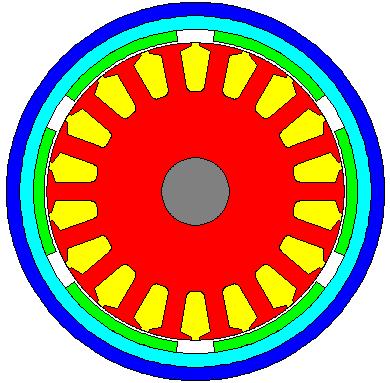
76 Segmented Motor Miniaturization Papers published in 2001 Existing Motor: 50mm active length 130mm long housing traditional lamination overlapping winding New Motor: 50mm active length 100mm long housing 34% more torque for same temperature rise segmented lamination non-overlapping winding In order to optimize the new design an iterative mix of electromagnetic and thermal analysis was performed


77 Segmented Motor Miniaturization Old motor inserted mush winding 54% slot-fill 80mm diameter 18-slots, 6-poles large end windings which overlap each other New Motor precision bobbin wound 82% slot-fill 80mm diameter 12-slots, 8-poles short end windings that are are non-overlapping


78 Segmented Motor Miniaturization Traditional Winding inserted mush winding 54% slot-fill Concentrated Winding precision bobbin wound 82% slot-fill Mixed EM/Thermal design: Iron losses have an easier path to the housing Optimum thermal design requires correct balance between copper & iron losses complex function of size, speed, materials, etc.

79 Improved winding insulation system Developed improved winding insulation in new designs New potting/impregnation materials with k = 1W/m/C previous materials have k = 0.2W/m/C above designs show 6%-8% reduction in temperature Above potted end-winding design shows a 15% reduced temperature compared to non-potted design Vacuum impregnation can eliminate air pockets above design shows 9% decrease in temperature in perfectly impregnated motor compared to old impregnation system

80 Improved housing for TENV motor o C optimum fin spacing spacing Motor-CAD analytical formulations for convection used to optimise the fin spacing small fin spacing has large surface area but reduced air flow large fin spacing has maximum air flow but reduced surface area Accuracy validated using tests on series of rectangular and circular discs and internal heater Also did CFD which gave same optimum but took a lot longer to set up the model and calculate

81 Axial Cooling Fin Optimization motors with shaft mounted fan or blower unit large thermal benefits possible with correct fin design large selection of fin types available in Motor-CAD


82 Selection of TEFC machines where axial fins optimized using thermal analysis 315mm Shaft Height, Cast Housing 200mm Shaft Height, Cast Housing 80mm Shaft Height, Aluminium Housing


 = 157ºC")
83 Through Ventilation Motor Through ventilated motor optimised using a mix of heat transfer and flow network analysis More details in paper from ICEM 2002 ventilation paths 1150hp IM Tw(test) = 157ºC Tw(calc) = 159ºC


84 Through Ventilation Few of the many ducting systems available for use in through ventilation thermal analysis flow circuit automatically calculated User can input the fan characteristic and the system flow resistance is calculated pressure fan characteristic flow calculation system resistance flow
85 Underwater Camera Motor winding turn off & take out of water (no loss/less cooling) housing Analysis carried out on motors driving propellers on a small submersible craft fitted with a camera Analysis to make sure that the housing temperature did not get too hot when the motor turned off and removed from the water Losses now zero and winding cools down but this heats up the housing which is now not liquid cooled

86 Minimization of Motor Size/Weight Aerospace Duty Cycle Analysis 1 2 winding 3 4 duty-cycle analysis on an aerospace application with a short term load requirement magnet the motor needed to operate on the duty cycles and just get to 180C Nm rpm time

87 Validation of Duty Cycle Thermal Transient Analysis (Aerospace) the complex load modelled in Motor-CAD is shown below: excellent agreement between the calculated thermal response and measured temperatures
88 Thermal Modeling of a Short-Duty Motor Motor designed to have minimum size and weight for a high performance short-duty cycle application. Optimization of thermal performance is critical for minimized weight and size Motor-CAD used for transient analysis and size optimisation Excellent agreement with test data when prototype built Temperature varation from calibrated value (K) Impgrenation goodness Wire insulation thickness Slot liner thickness Slot liner-lamination gap Ratio of parameter variation from calibrated value Winding temperature rise with DC currents (0.2 to 1.1 p.u.) - Test & Motor-CAD


89 IPM Traction Motor Optimisation of water jacket for a traction motor Excellent agreement with test data when prototype built showing level of confidence in default values for manufacturing issues like the stator-lamination interface gap ECCE 2011


90 BPM Traction Motor Motor-CAD used to optimise cooling of traction motor Motor had open endcap with local convection cooling of end-windings Excellent accuracy shown with fast calculation times
![Automotive PMDC - Improved Winding Insulation System Temperature [ C] 220 200 180 160 140 120 100 80 60 40 Nomex Liner Twinding [Test] Trotor](/docs-images/79/80126721/images/91-0.jpg "[Test] Tmagnet [Test] Tcomm [Test] Thousing [Test] Twinding [Calc] Trotor [Calc] Tmagnet [Calc] Tcomm [Calc] Thousing [Calc] ICEM 2008")

![8 minutes Measured and simulated results shown Temperature [ C] 20 220 200 180 160 140 120 100 80 60 40 20 0 2 4 6 8 10 time [min] Powder](/docs-images/79/80126721/images/91-2.jpg "Liner Twinding [Test] Trotor [Test] Tmagnet [Test] Tcomm [Test] Thousing [Test] Twinding [Calc] Trotor [Calc] Tmagnet [Calc] Tcomm [Calc]")
91 Automotive PMDC - Improved Winding Insulation System Temperature [ C] Nomex Liner Twinding [Test] Trotor [Test] Tmagnet [Test] Tcomm [Test] Thousing [Test] Twinding [Calc] Trotor [Calc] Tmagnet [Calc] Tcomm [Calc] Thousing [Calc] ICEM 2008 electro-hydraulic brake Optimisated impregnation process and slot liner to allow a longer operation time Two transients shown Same load of 20A locked rotor One has Nomex liner and the other a powder liner Powder liner allows 4 minute load rather than 1.8 minutes Measured and simulated results shown Temperature [ C] time [min] Powder Liner Twinding [Test] Trotor [Test] Tmagnet [Test] Tcomm [Test] Thousing [Test] Twinding [Calc] Trotor [Calc] Tmagnet [Calc] Tcomm [Calc] Thousing [Calc] time [min]
![Automotive PMDC Brush Model Temperature [ C] 170.](/docs-images/79/80126721/images/92-0.jpg "00 160.00 150.00 140.")
![00 -ve Brush [TEST] +ve Brush [TEST] Brush [CALC]](/docs-images/79/80126721/images/92-1.jpg "Temperature [ C] 160.00 150.00 140.00 130.00 120.")

![00 time [s] 80.00 100.00 120.](/docs-images/79/80126721/images/92-4.jpg "00 Improved brush model developed with aid of")
92 Automotive PMDC Brush Model Temperature [ C] ve Brush [TEST] +ve Brush [TEST] Brush [CALC] Temperature [ C] ve Brush [TEST] +ve Brush [TEST] Brush [CALC] time [s] time [s] Improved brush model developed with aid of extensive testing
93 Servo Motor Duty Cycle Analysis Prediction of a motor thermal performance on a duty cycle load is important to match the motor to the load excellent agreement between the prediction and test data shown winding calculation test short time constant of winding leads to rapid heating flange 3 x full-load / 0.5 x full-load housing long time constant of motor bulk

94 Servo Motor Duty Cycle Analysis Range of tests with different duty cycles used to proved model symbols = Motor-CAD model lines = test data

95 Servo Motor Duty Cycle Analysis Again for another servo motor design excellent agreement between test and calculation PEMD 2006

96 Induction Motor Locked Rotor Analysis excellent agreement between test and calculation of induction machine transient on locked rotor Iterative calculation between SPEED and Motor-CAD Work done by Dave Dorrell at Glasgow University IECON 2006


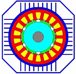
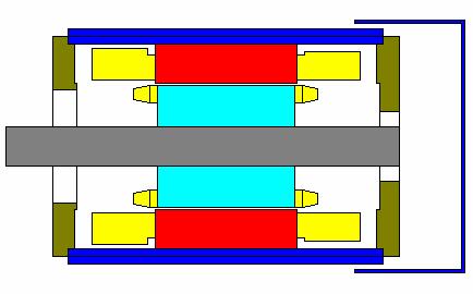
97 Outer Rotor Brushless Motor Project with University of Bristol to optimise the cooling of this outer rotor BPM machine More complex cooling than traditional inner rotor machine


98 TEFC & TENV Synchronous Gens. Range of machines tested and modelled with good level of agreement Mostly <5% error Cummins Generator Technologies and Edinburgh University TENV Cooling: TEFC Cooling:

99 Wind Generator Thermal Analysis Wind generator (University of Cantabria) FLUX Users meeting 2010 Excellent results with Motor-CAD v Test Fault Analysis also performed


100 Motor size and weight reduction Motor-CAD enabled a sizable reduction in size and weight compared to if no thermal analysis was done at the design stage Weight reduction 31% Volume reduction 39% UK Magnetics Society Meeting 2008
101 Thank you for your attention! Are there any questions?
STAR-CCM+ and SPEED for electric machine cooling analysis
 STAR-CCM+ and SPEED for electric machine cooling analysis Dr. Markus Anders, Dr. Stefan Holst, CD-adapco Abstract: This paper shows how two well established software programs can be used to determine the
TEFC Induction Motors Thermal Models: A Parameter Sensitivity Analysis
 TEFC Induction Motors Thermal Models: A Parameter Sensitivity Analysis A.Boglietti*, A. Cavagnino*, D.A. Staton # Dip. Ingegneria Elettrica Industriale - Politecnico di Torino C.so Duca degli Abruzzi,
Y.K. Chin, D.A. Staton
 Transient Thermal Analysis using both Lumped- Circuit Approach and Finite Element Method of a Permanent Magnet Traction Motor Y.K. Chin, D.A. Staton Abstract This paper presents the transient thermal analysis
Design of the Forced Water Cooling System for a Claw Pole Transverse Flux Permanent Magnet Synchronous Motor
 Design of the Forced Water Cooling System for a Claw Pole Transverse Flux Permanent Magnet Synchronous Motor Ahmad Darabi 1, Ali Sarreshtehdari 2, and Hamed Tahanian 1 1 Faculty of Electrical and Robotic
Thermal Analysis & Design Improvement of an Internal Air-Cooled Electric Machine Dr. James R. Dorris Application Specialist, CD-adapco
 Thermal Analysis & Design Improvement of an Internal Air-Cooled Electric Machine Dr. James R. Dorris Application Specialist, CD-adapco Thermal Analysis of Electric Machines Motivation Thermal challenges
Solving the More Difficult Aspects of Electric Motor Thermal Analysis
 Solving the More Difficult Aspects of Electric Motor Thermal Analysis Dave Staton #, Aldo Boglietti *, Andrea Cavagnino * # Motor Design Ltd., 1 Eaton Court, Tetchill, Ellesmere, Shropshire, UK, SY12 9DA
EVS28 KINTEX, Korea, May 3-6, 2015
 EVS28 KINTEX, Korea, May 3-6, 2015 Comparison of Thermal Performance between Direct Coil Cooling and Water Jacket Cooling for Electric Traction Motor based on Lumped Parameter Thermal Network and Experimentation
Study and Characterization of the Limiting Thermal Phenomena in Low-Speed Permanent Magnet Synchronous Generators for Wind Energy
 1 Study and Characterization of the Limiting Thermal Phenomena in Low-Speed Permanent Magnet Synchronous Generators for Wind Energy Mariana Cavique, Student, DEEC/AC Energia, João F.P. Fernandes, LAETA/IDMEC,
Influence of Different End Region Cooling Arrangements on End-Winding Heat Transfer Coefficients in Electrical Machines
 Influence of Different End Region Cooling Arrangements on End-Winding Heat Transfer Coefficients in Electrical Machines David A. Staton 1 Mircea Popescu 1 Douglas Hawkins 1 Member Senior Member Aldo Boglietti
If there is convective heat transfer from outer surface to fluid maintained at T W.
 Heat Transfer 1. What are the different modes of heat transfer? Explain with examples. 2. State Fourier s Law of heat conduction? Write some of their applications. 3. State the effect of variation of temperature
ELEC9712 High Voltage Systems. 1.2 Heat transfer from electrical equipment
 ELEC9712 High Voltage Systems 1.2 Heat transfer from electrical equipment The basic equation governing heat transfer in an item of electrical equipment is the following incremental balance equation, with
UNIT II CONVECTION HEAT TRANSFER
 UNIT II CONVECTION HEAT TRANSFER Convection is the mode of heat transfer between a surface and a fluid moving over it. The energy transfer in convection is predominately due to the bulk motion of the fluid
IN THE PAST, the thermal analysis of electric machines has
 IEEE TRANSACTIONS ON INDUSTRIAL ELECTRONICS, VOL. 56, NO. 3, MARCH 2009 871 Evolution and Modern Approaches for Thermal Analysis of Electrical Machines Aldo Boglietti, Senior Member, IEEE, Andrea Cavagnino,
PHYSICAL MECHANISM OF NATURAL CONVECTION
 1 NATURAL CONVECTION In this chapter, we consider natural convection, where any fluid motion occurs by natural means such as buoyancy. The fluid motion in forced convection is quite noticeable, since a
Transient Heat Transfer Experiment. ME 331 Introduction to Heat Transfer. June 1 st, 2017
 Transient Heat Transfer Experiment ME 331 Introduction to Heat Transfer June 1 st, 2017 Abstract The lumped capacitance assumption for transient conduction was tested for three heated spheres; a gold plated
UNIT I INTRODUCTION Part A- Two marks questions
 ROEVER COLLEGE OF ENGINEERING & TECHNOLOGY ELAMBALUR, PERAMBALUR-621220 DEPARTMENT OF ELECTRICAL AND ELECTRONICS ENGINEERING DESIGN OF ELECTRICAL MACHINES UNIT I INTRODUCTION 1. Define specific magnetic
Thermal and Mechanical Analysis of PM Assisted Synchronous Reluctance Motor for Washing Machines
 Thermal and Mechanical Analysis of PM Assisted Synchronous Reluctance Motor for Washing Machines Liridon Xheladini, Alper Tap, Murat Imeryuz, Tasdemir Asan, Murat Yilmaz, Lale T. Ergene Electrical Engineering
L10 Thermal Design. EIEN20 Design of Electrical Machines, IEA, Forced cooling. Heat dissipation. Previously.
 L Thermal Design Forced cooling Heat dissipation Life span of e electrical machines Cooling channel 36 mm long mm wide.5 mm parallel plates Convection - W/m K Empiric vs FEM Flow rate Previous - m 3 /min
Chapter 3 NATURAL CONVECTION
 Fundamentals of Thermal-Fluid Sciences, 3rd Edition Yunus A. Cengel, Robert H. Turner, John M. Cimbala McGraw-Hill, 2008 Chapter 3 NATURAL CONVECTION Mehmet Kanoglu Copyright The McGraw-Hill Companies,
Analysis of the Cooling Design in Electrical Transformer
 Analysis of the Cooling Design in Electrical Transformer Joel de Almeida Mendes E-mail: joeldealmeidamendes@hotmail.com Abstract This work presents the application of a CFD code Fluent to simulate the
CHAPTER 7 NUMERICAL MODELLING OF A SPIRAL HEAT EXCHANGER USING CFD TECHNIQUE
 CHAPTER 7 NUMERICAL MODELLING OF A SPIRAL HEAT EXCHANGER USING CFD TECHNIQUE In this chapter, the governing equations for the proposed numerical model with discretisation methods are presented. Spiral
Design and analysis of Axial Flux Permanent Magnet Generator for Direct-Driven Wind Turbines
 Design and analysis of Axial Flux Permanent Magnet Generator for Direct-Driven Wind Turbines Sung-An Kim, Jian Li, Da-Woon Choi, Yun-Hyun Cho Dep. of Electrical Engineering 37, Nakdongdae-ro, 55beon-gil,
Heat Transfer Convection
 Heat ransfer Convection Previous lectures conduction: heat transfer without fluid motion oday (textbook nearly 00 pages) Convection: heat transfer with fluid motion Research methods different Natural Convection
Natural convection heat transfer around a horizontal circular cylinder near an isothermal vertical wall
 Natural convection heat transfer around a horizontal circular cylinder near an isothermal vertical wall Marcel Novomestský 1, Richard Lenhard 1, and Ján Siažik 1 1 University of Žilina, Faculty of Mechanical
Preliminary Sizing Design of a 1 MW Low Duty Cycle Switched Reluctance Generator for Aerospace Applications
 Preliminary Sizing Design of a 1 MW Low Duty Cycle Switched Reluctance Generator for Aerospace Applications Jin-Woo Jung, Ph. D. Student Advisors: Prof. Ali Keyhani Adjunct Prof. Tomy Sebastian Oct. 25,
Chapter 8 COOLING AND HEAT TRANSFER. 8.1 Importance of thermal analysis. 8.2 Heat transfer modes
 Chapter 8 COOLING AND HEAT TRANSFER 8.1 Importance of thermal analysis During the operation of an electrical machine, heat is generated due to power losses in electric and magnetic circuits and mechanical
Convection Heat Transfer. Introduction
 Convection Heat Transfer Reading Problems 12-1 12-8 12-40, 12-49, 12-68, 12-70, 12-87, 12-98 13-1 13-6 13-39, 13-47, 13-59 14-1 14-4 14-18, 14-24, 14-45, 14-82 Introduction Newton s Law of Cooling Controlling
Chapter 6: Efficiency and Heating. 9/18/2003 Electromechanical Dynamics 1
 Chapter 6: Efficiency and Heating 9/18/2003 Electromechanical Dynamics 1 Losses As a machine transforms energy from one form to another there is always a certain power loss the loss is expressed as heat,
Keywords: Electric Machines, Rotating Machinery, Stator faults, Fault tolerant control, Field Weakening, Anisotropy, Dual rotor, 3D modeling
 Analysis of Electromagnetic Behavior of Permanent Magnetized Electrical Machines in Fault Modes M. U. Hassan 1, R. Nilssen 1, A. Røkke 2 1. Department of Electrical Power Engineering, Norwegian University
Lumped parameter thermal modelling
 Chapter 3 umped parameter thermal modelling This chapter explains the derivation of a thermal model for a PMSM by combining a lumped parameter (P) model and an analytical distributed model. The whole machine
Motor-CAD combined electromagnetic and thermal model (January 2015)
") Motor-CAD combined electromagnetic and thermal model (January 2015) Description The Motor-CAD allows the machine performance, losses and temperatures to be calculated for a BPM machine. In this tutorial
Motor-CAD combined electromagnetic and thermal model (January 2015) Description The Motor-CAD allows the machine performance, losses and temperatures to be calculated for a BPM machine. In this tutorial
Water-Cooled Direct Drive Permanent Magnet Motor Design in Consideration of its Efficiency and Structural Strength
 Journal of Magnetics 18(2), 125-129 (2013) ISSN (Print) 1226-1750 ISSN (Online) 2233-6656 http://dx.doi.org/10.4283/jmag.2013.18.2.125 Water-Cooled Direct Drive Permanent Magnet Motor Design in Consideration
Prof. N. V. Sali 1, Pooja Kulkarni 2 1, 2
 Lumped Parameter Analysis of SMPM Synchronous Electric Motor used for Hybrid Electric Vehicle Traction Drive Prof. N. V. Sali 1, Pooja Kulkarni 2 1, 2 Department of Mechanical Engineering, Govt. College
CHAPTER 3 INFLUENCE OF STATOR SLOT-SHAPE ON THE ENERGY CONSERVATION ASSOCIATED WITH THE SUBMERSIBLE INDUCTION MOTORS
 38 CHAPTER 3 INFLUENCE OF STATOR SLOT-SHAPE ON THE ENERGY CONSERVATION ASSOCIATED WITH THE SUBMERSIBLE INDUCTION MOTORS 3.1 INTRODUCTION The electric submersible-pump unit consists of a pump, powered by
Thermal Properties of a Prototype Permanent Magnetized Electrical Motor Embedded in a Rim Driven Thruster
 Thermal Properties of a Prototype Permanent Magnetized Electrical Motor Embedded in a Rim Driven Thruster Øystein Krøvel Knut Andresen Normann Sandøy Abstract For machine designs it is usually the thermal
CHAPTER 3 ENERGY EFFICIENT DESIGN OF INDUCTION MOTOR USNG GA
 31 CHAPTER 3 ENERGY EFFICIENT DESIGN OF INDUCTION MOTOR USNG GA 3.1 INTRODUCTION Electric motors consume over half of the electrical energy produced by power stations, almost the three-quarters of the
The Nottingham eprints service makes this work by researchers of the University of Nottingham available open access under the following conditions.
 Arumugam, Puvaneswaran and Dusek, Jiri and Mezani, Smail and Hamiti, Tahar and Gerada, C. (2015) Modeling and analysis of eddy current losses in permanent magnet machines with multi-stranded bundle conductors.
Chapter 3: Fundamentals of Mechanics and Heat. 1/11/00 Electromechanical Dynamics 1
 Chapter 3: Fundamentals of Mechanics and Heat 1/11/00 Electromechanical Dynamics 1 Force Linear acceleration of an object is proportional to the applied force: F = m a x(t) F = force acting on an object
TEMPERATURE EFFECTS ON MOTOR PERFORMANCE
 TEMPERATURE EFFECTS ON MOTOR PERFORMANCE Authored By: Dan Montone Haydon Kerk Motion Solutions / Pittman Motors hen applying DC motors to any type of application, temperature effects need to be considered
MYcsvtu Notes HEAT TRANSFER BY CONVECTION
 www.mycsvtunotes.in HEAT TRANSFER BY CONVECTION CONDUCTION Mechanism of heat transfer through a solid or fluid in the absence any fluid motion. CONVECTION Mechanism of heat transfer through a fluid in
Journal of Engineering Research and Studies E-ISSN
 Research Article EXPERIMENTAL AND COMPUTATIONAL ANALYSIS AND OPTIMIZATION FOR HEAT TRANSFER THROUGH FINS WITH DIFFERENT TYPES OF NOTCH S.H. Barhatte 1, M. R. Chopade 2, V. N. Kapatkar 3 Address for Correspondence
Experimental Analysis of Rectangular Fin Arrays with Continuous Fin and Interrupted Fins Using Natural and Forced Convection
 Experimental Analysis of Rectangular Fin Arrays with Continuous Fin and Interrupted Fins Using Natural and Forced Convection Vinaya Kumara U M 1, Mr. Krishnamurthy K.N 2, Akash Deep B N 3 P.G. Student,
Convection. forced convection when the flow is caused by external means, such as by a fan, a pump, or atmospheric winds.
 Convection The convection heat transfer mode is comprised of two mechanisms. In addition to energy transfer due to random molecular motion (diffusion), energy is also transferred by the bulk, or macroscopic,
Induction Motors. The single-phase induction motor is the most frequently used motor in the world
 Induction Motor The single-phase induction motor is the most frequently used motor in the world Most appliances, such as washing machines and refrigerators, use a single-phase induction machine Highly
PHYSICAL MECHANISM OF CONVECTION
 Tue 8:54:24 AM Slide Nr. 0 of 33 Slides PHYSICAL MECHANISM OF CONVECTION Heat transfer through a fluid is by convection in the presence of bulk fluid motion and by conduction in the absence of it. Chapter
HEAT TRANSFER BY CONVECTION. Dr. Şaziye Balku 1
 HEAT TRANSFER BY CONVECTION Dr. Şaziye Balku 1 CONDUCTION Mechanism of heat transfer through a solid or fluid in the absence any fluid motion. CONVECTION Mechanism of heat transfer through a fluid in the
Accurate Joule Loss Estimation for Rotating Machines: An Engineering Approach
 Accurate Joule Loss Estimation for Rotating Machines: An Engineering Approach Adeeb Ahmed Department of Electrical and Computer Engineering North Carolina State University Raleigh, NC, USA aahmed4@ncsu.edu
Principles of Convection
 Principles of Convection Point Conduction & convection are similar both require the presence of a material medium. But convection requires the presence of fluid motion. Heat transfer through the: Solid
Design Optimization of Electric Motor Frame and Its Study for Thermal, Dynamic and Modal Stability
 Design Optimization of Electric Motor Frame and Its Study for Thermal, Dynamic and Modal Stability Pavankumar V Kulkarni 1, Dr. S. R. Basavaraddi 2 1Dept. of Mechanical Engineering, KLE Dr. M. S. S. College
Encoders. Understanding. November design for industry: Help clean up the ocean. Horizon failure forensics
 November 2013 www.designworldonline.com INSIDE: design for industry: Help clean up the ocean Page 18 3D CAD: FEA aids Deepwater Horizon failure forensics Page 37 Understanding NETWORKING: Enhancing enterprise
TankExampleNov2016. Table of contents. Layout
 Table of contents Task... 2 Calculation of heat loss of storage tanks... 3 Properties ambient air Properties of air... 7 Heat transfer outside, roof Heat transfer in flow past a plane wall... 8 Properties
Heat Transfer Analysis of Machine Tool Main Spindle
 Technical Paper Heat Transfer Analysis of Machine Tool Main Spindle oshimitsu HIRASAWA Yukimitsu YAMAMOTO CAE analysis is very useful for shortening development time and reducing the need for development
Generators for wind power conversion
 Generators for wind power conversion B. G. Fernandes Department of Electrical Engineering Indian Institute of Technology, Bombay Email : bgf@ee.iitb.ac.in Outline of The Talk Introduction Constant speed
Jerad P. 10/1/2015. Motor Thermal Limits on Torque Production (Frameless Motor Level)
") Jerad P. 10/1/015 Motor Thermal Limits on Torque Production (Frameless Motor Level) Jerad P. 10/1/015 The theory of operation of a frameless permanent magnet motor (PMM) and its thermal limitations is
Jerad P. 10/1/015 Motor Thermal Limits on Torque Production (Frameless Motor Level) Jerad P. 10/1/015 The theory of operation of a frameless permanent magnet motor (PMM) and its thermal limitations is
ADAM PIŁAT Department of Automatics, AGH University of Science and Technology Al. Mickiewicza 30, Cracow, Poland
 Int. J. Appl. Math. Comput. Sci., 2004, Vol. 14, No. 4, 497 501 FEMLAB SOFTWARE APPLIED TO ACTIVE MAGNETIC BEARING ANALYSIS ADAM PIŁAT Department of Automatics, AGH University of Science and Technology
Department of Mechanical Engineering ME 96. Free and Forced Convection Experiment. Revised: 25 April Introduction
 CALIFORNIA INSTITUTE OF TECHNOLOGY Department of Mechanical Engineering ME 96 Free and Forced Convection Experiment Revised: 25 April 1994 1. Introduction The term forced convection refers to heat transport
Studies on flow through and around a porous permeable sphere: II. Heat Transfer
 Studies on flow through and around a porous permeable sphere: II. Heat Transfer A. K. Jain and S. Basu 1 Department of Chemical Engineering Indian Institute of Technology Delhi New Delhi 110016, India
Optimal Design of PM Axial Field Motor Based on PM Radial Field Motor Data
 Optimal Design of PM Axial Field Motor Based on PM Radial Field Motor Data GOGA CVETKOVSKI LIDIJA PETKOVSKA Faculty of Electrical Engineering Ss. Cyril and Methodius University Karpos II b.b. P.O. Box
Chapter 9 NATURAL CONVECTION
 Heat and Mass Transfer: Fundamentals & Applications Fourth Edition in SI Units Yunus A. Cengel, Afshin J. Ghajar McGraw-Hill, 2011 Chapter 9 NATURAL CONVECTION PM Dr Mazlan Abdul Wahid Universiti Teknologi
University of Bristol - Explore Bristol Research. Peer reviewed version. Link to published version (if available): /cp.2016.
: /cp.2016.") Simpson, N., Wrobel, R., Booker, J., & Mellor, P. (016). Multi-Physics Experimental Investigation into Stator-Housing Contact Interface. In 8th IET International Conference on Power Electronics, Machines
Simpson, N., Wrobel, R., Booker, J., & Mellor, P. (016). Multi-Physics Experimental Investigation into Stator-Housing Contact Interface. In 8th IET International Conference on Power Electronics, Machines
Pin Fin Lab Report Example. Names. ME331 Lab
 Pin Fin Lab Report Example Names ME331 Lab 04/12/2017 1. Abstract The purposes of this experiment are to determine pin fin effectiveness and convective heat transfer coefficients for free and forced convection
THERMAL MODELLING OF A LOW SPEED AIR-COOLED AXIAL FLUX PERMANENT MAGNET GENERATOR
 THERMAL MODELLING OF A LOW SPEED AIR-COOLED AXIAL FLUX PERMANENT MAGNET GENERATOR Y.C. Chong*, J. Chick*, M.A. Mueller*, D.A. Staton, A.S. McDonald # * Institute for Energy Systems, School of Engineering,
Phone: , For Educational Use. SOFTbank E-Book Center, Tehran. Fundamentals of Heat Transfer. René Reyes Mazzoco
 8 Fundamentals of Heat Transfer René Reyes Mazzoco Universidad de las Américas Puebla, Cholula, Mexico 1 HEAT TRANSFER MECHANISMS 1.1 Conduction Conduction heat transfer is explained through the molecular
Iterative calculation of the heat transfer coefficient
 Iterative calculation of the heat transfer coefficient D.Roncati Progettazione Ottica Roncati, Ferrara - Italy Aim The plate temperature of a cooling heat sink is an important parameter that has to be
watts ( )horsepower 746 = watts 124 watts 6 horsepower Question:
horsepower 746 = watts 124 watts 6 horsepower Question:") Question: Answer: A neighbor recently asked me if his evaporative air conditioner was running correctly because he felt the blower drive motor and it was too hot to leave his hand on it for long. I was
Question: Answer: A neighbor recently asked me if his evaporative air conditioner was running correctly because he felt the blower drive motor and it was too hot to leave his hand on it for long. I was
Outlines. simple relations of fluid dynamics Boundary layer analysis. Important for basic understanding of convection heat transfer
 Forced Convection Outlines To examine the methods of calculating convection heat transfer (particularly, the ways of predicting the value of convection heat transfer coefficient, h) Convection heat transfer
Tutorial 1. Where Nu=(hl/k); Reynolds number Re=(Vlρ/µ) and Prandtl number Pr=(µCp/k)
; Reynolds number Re=(Vlρ/µ) and Prandtl number Pr=(µCp/k)") Tutorial 1 1. Explain in detail the mechanism of forced convection. Show by dimensional analysis (Rayleigh method) that data for forced convection may be correlated by an equation of the form Nu = φ (Re,
Tutorial 1 1. Explain in detail the mechanism of forced convection. Show by dimensional analysis (Rayleigh method) that data for forced convection may be correlated by an equation of the form Nu = φ (Re,
Analysis, Design and Fabrication of Forced Convection Apparatus
 Analysis, Design and Fabrication of Forced Convection Apparatus Shajan K. Thomas 1, Vishnukumar C M 2, Vishnu C J 3, Alex Baby 4 Assistant Professor, Dept. of Mechanical Engineering, Toc H Institute of
Extensions to the Finite Element Technique for the Magneto-Thermal Analysis of Aged Oil Cooled-Insulated Power Transformers
 Journal of Electromagnetic Analysis and Applications, 2012, 4, 167-176 http://dx.doi.org/10.4236/jemaa.2012.44022 Published Online April 2012 (http://www.scirp.org/journal/jemaa) 167 Extensions to the
THERMAL FIELD ANALYSIS IN DESIGN AND MANUFACTURING OF A PERMANENT MAGNET LINEAR SYNCHRONOUS MOTOR
 THERMAL FIELD ANALYSIS IN DESIGN AND MANUFACTURING OF A PERMANENT MAGNET LINEAR SYNCHRONOUS MOTOR Petar UZUNOV 1 ABSTRACT: The modern Permanent Magnet Linear Synchronous Motors (PMLSM) has a wide range
Parameter Prediction and Modelling Methods for Traction Motor of Hybrid Electric Vehicle
 Page 359 World Electric Vehicle Journal Vol. 3 - ISSN 232-6653 - 29 AVERE Parameter Prediction and Modelling Methods for Traction Motor of Hybrid Electric Vehicle Tao Sun, Soon-O Kwon, Geun-Ho Lee, Jung-Pyo
University of Bristol - Explore Bristol Research. Peer reviewed version. Link to published version (if available): /ECCE.2016.
: /ECCE.2016.") Ayat, S., Wrobel, R., Goss, J., & Drury, D. (2017). Experimental calibration in thermal analysis of PM electrical machines. In ECCE 2016 - IEEE Energy Conversion Congress and Exposition, Proceedings [7855093]
Ayat, S., Wrobel, R., Goss, J., & Drury, D. (2017). Experimental calibration in thermal analysis of PM electrical machines. In ECCE 2016 - IEEE Energy Conversion Congress and Exposition, Proceedings [7855093]
Chapter 5 MATHEMATICAL MODELING OF THE EVACATED SOLAR COLLECTOR. 5.1 Thermal Model of Solar Collector System
 Chapter 5 MATHEMATICAL MODELING OF THE EVACATED SOLAR COLLECTOR This chapter deals with analytical method of finding out the collector outlet working fluid temperature. A dynamic model of the solar collector
OPTIMAL DESIGN OF CLUTCH PLATE BASED ON HEAT AND STRUCTURAL PARAMETERS USING CFD AND FEA
 International Journal of Mechanical Engineering and Technology (IJMET) Volume 9, Issue 5, May 2018, pp. 717 724, Article ID: IJMET_09_05_079 Available online at http://www.iaeme.com/ijmet/issues.asp?jtype=ijmet&vtype=9&itype=5
AN EXPERIMENTAL STUDY OF ROTATIONAL PRESSURE LOSS IN ROTOR DUCTS
 AN EXPERIMENTAL STUDY OF ROTATIONAL PRESSURE LOSS IN ROTOR DUCTS Y. C. Chong *, eddie.chong@motor-design.com D. A. Staton #, dave.staton@motor-design.com M. A. Mueller, Markus.Mueller@ed.ac.uk J. Chick,
Transient thermal modelling of an Axial Flux Permanent Magnet (AFPM) machine with model parameter optimisation using a Monte Carlo method
 machine with model parameter optimisation using a Monte Carlo method") Transient thermal modelling of an Axial Flux Permanent Magnet (AFPM) machine with model parameter optimisation using a Monte Carlo method J. Hey 1, D. A. Howey 1, R. Martinez-Botas 1, M. Lamperth 2 1 Mechanical
Transient thermal modelling of an Axial Flux Permanent Magnet (AFPM) machine with model parameter optimisation using a Monte Carlo method J. Hey 1, D. A. Howey 1, R. Martinez-Botas 1, M. Lamperth 2 1 Mechanical
Experiment 1. Measurement of Thermal Conductivity of a Metal (Brass) Bar
 Bar") Experiment 1 Measurement of Thermal Conductivity of a Metal (Brass) Bar Introduction: Thermal conductivity is a measure of the ability of a substance to conduct heat, determined by the rate of heat flow
Experiment 1 Measurement of Thermal Conductivity of a Metal (Brass) Bar Introduction: Thermal conductivity is a measure of the ability of a substance to conduct heat, determined by the rate of heat flow
Transport processes. 7. Semester Chemical Engineering Civil Engineering
 Transport processes 7. Semester Chemical Engineering Civil Engineering 1. Elementary Fluid Dynamics 2. Fluid Kinematics 3. Finite Control Volume Analysis 4. Differential Analysis of Fluid Flow 5. Viscous
Natural Convection from a Long Horizontal Cylinder
 Natural Convection from a Long Horizontal Cylinder Hussein Awad Kurdi Saad Engineering Technical College of Al Najaf, Al-Furat Al-Awsat Technical University, Iraq ABSTRACT: Natural convection from a Long
Electromagnetics and Electric Machines Stefan Holst, CD-adapco
 Electromagnetics and Electric Machines Stefan Holst, CD-adapco Overview Electric machines intro Designing electric machines with SPEED Links to STAR-CCM+ for thermal modeling Electromagnetics in STAR-CCM+
Introduction to Heat Transfer
 Question Bank CH302 Heat Transfer Operations Introduction to Heat Transfer Question No. 1. The essential condition for the transfer of heat from one body to another (a) Both bodies must be in physical
EDEXCEL NATIONAL CERTIFICATE/DIPLOMA UNIT 5 - ELECTRICAL AND ELECTRONIC PRINCIPLES NQF LEVEL 3. OUTCOME 3 - MAGNETISM and INDUCTION
 EDEXCEL NATIONAL CERTIFICATE/DIPLOMA UNIT 5 - ELECTRICAL AND ELECTRONIC PRINCIPLES NQF LEVEL 3 OUTCOME 3 - MAGNETISM and INDUCTION 3 Understand the principles and properties of magnetism Magnetic field:
The Marinov Generator Cyril Smith, May 2009
 The Marinov Generator Cyril Smith, May 2009 1. Introduction The late Stephan Marinov experimented with a form of electric motor that he bizarrely called Siberian Coliu. This motor has been discussed by
Department of Energy Science & Engineering, IIT Bombay, Mumbai, India. *Corresponding author: Tel: ,
 ICAER 2011 AN EXPERIMENTAL AND COMPUTATIONAL INVESTIGATION OF HEAT LOSSES FROM THE CAVITY RECEIVER USED IN LINEAR FRESNEL REFLECTOR SOLAR THERMAL SYSTEM Sudhansu S. Sahoo* a, Shinu M. Varghese b, Ashwin
Application of Computational Fluid Dynamics (CFD) On Ventilation-Cooling Optimization of Electrical Machines
 On Ventilation-Cooling Optimization of Electrical Machines") Application of Computational Fluid Dynamics (CFD) On Ventilation-Cooling Optimization of Electrical Machines Ryuichi Ujiie, Dr Raphael Arlitt, Hirofumi Etoh Voith Siemens Hydro Power Generation RyuichiUjiie@vs-hydrocom,
Application of Computational Fluid Dynamics (CFD) On Ventilation-Cooling Optimization of Electrical Machines Ryuichi Ujiie, Dr Raphael Arlitt, Hirofumi Etoh Voith Siemens Hydro Power Generation RyuichiUjiie@vs-hydrocom,
C ONTENTS CHAPTER TWO HEAT CONDUCTION EQUATION 61 CHAPTER ONE BASICS OF HEAT TRANSFER 1 CHAPTER THREE STEADY HEAT CONDUCTION 127
 C ONTENTS Preface xviii Nomenclature xxvi CHAPTER ONE BASICS OF HEAT TRANSFER 1 1-1 Thermodynamics and Heat Transfer 2 Application Areas of Heat Transfer 3 Historical Background 3 1-2 Engineering Heat
Conjugate heat transfer from an electronic module package cooled by air in a rectangular duct
 Conjugate heat transfer from an electronic module package cooled by air in a rectangular duct Hideo Yoshino a, Motoo Fujii b, Xing Zhang b, Takuji Takeuchi a, and Souichi Toyomasu a a) Fujitsu Kyushu System
Convective Mass Transfer
 Convective Mass Transfer Definition of convective mass transfer: The transport of material between a boundary surface and a moving fluid or between two immiscible moving fluids separated by a mobile interface
Introduction to Heat and Mass Transfer. Week 14
 Introduction to Heat and Mass Transfer Week 14 HW # 7 prob. 2 Hot water at 50C flows through a steel pipe (thermal conductivity 14 W/m-K) of 100 mm outside diameter and 8 mm wall thickness. During winter,
Optimisation of Inner Diameter to Outer Diameter Ratio of Axial Flux Permanent Magnet Generator
 IOSR Journal of Electrical and Electronics Engineering (IOSR-JEEE) e-issn: 2278-1676,p-ISSN: 220-1, Volume 9, Issue 6 Ver. III (Nov Dec. 2014), PP 4-47 Optimisation of Inner Diameter to Outer Diameter
Building heat system sizing
 May 6th, 203 MVK60 Heat and Mass Transfer Project report Building heat system sizing Arnaud BELTOISE Dept. of Energy Sciences, Faculty of Engineering, Lund University, Box 8, 2200 Lund, Sweden . Introduction
Lecture 9 Thermal Analysis
 Lecture 9 Thermal Analysis 16.0 Release Introduction to ANSYS Mechanical 1 2015 ANSYS, Inc. February 27, 2015 Chapter Overview In this chapter, performing steady-state thermal analyses in Mechanical will
Exergy Analysis of Solar Air Collector Having W Shaped Artificial Roughness
 Advances in Materials Science and Mechanical Engineering Research Volume 1, Number 1 (2015), pp. 25-32 International Research Publication House http://www.irphouse.com Exergy Analysis of Solar Air Collector
Enhancement of Natural Convection Heat Transfer within Closed Enclosure Using Parallel Fins F. A. Gdhaidh, K. Hussain, H. S. Qi
 Enhancement of Natural Convection Heat Transfer within Closed Enclosure Using Parallel Fins F. A. Gdhaidh, K. Hussain, H. S. Qi Abstract A numerical study of natural convection heat transfer in water filled
Keywords: Spiral plate heat exchanger, Heat transfer, Nusselt number
 EXPERIMENTAL AND NUMERICAL STUDIES OF A SPIRAL PLATE HEAT EXCHANGER Dr.RAJAVEL RANGASAMY Professor and Head, Department of Mechanical Engineering Velammal Engineering College,Chennai -66,India Email:rajavelmech@gmail.com
Table of Contents. Foreword... xiii. Preface... xv
 Table of Contents Foreword.... xiii Preface... xv Chapter 1. Fundamental Equations, Dimensionless Numbers... 1 1.1. Fundamental equations... 1 1.1.1. Local equations... 1 1.1.2. Integral conservation equations...
Technical Notes. Introduction. PCB (printed circuit board) Design. Issue 1 January 2010
 Design. Issue 1 January 2010") Technical Notes Introduction Thermal Management for LEDs Poor thermal management can lead to early LED product failure. This Technical Note discusses thermal management techniques and good system design.
Technical Notes Introduction Thermal Management for LEDs Poor thermal management can lead to early LED product failure. This Technical Note discusses thermal management techniques and good system design.
Equal Pitch and Unequal Pitch:
 Equal Pitch and Unequal Pitch: Equal-Pitch Multiple-Stack Stepper: For each rotor stack, there is a toothed stator segment around it, whose pitch angle is identical to that of the rotor (θs = θr). A stator
PESIT Bangalore South Campus Hosur road, 1km before Electronic City, Bengaluru -100 Department of Electronics & Communication Engineering
 QUESTION PAPER INTERNAL ASSESSMENT TEST 2 Date : /10/2016 Marks: 0 Subject & Code: BASIC ELECTRICAL ENGINEERING -15ELE15 Sec : F,G,H,I,J,K Name of faculty : Dhanashree Bhate, Hema B, Prashanth V Time :
ECE309 INTRODUCTION TO THERMODYNAMICS & HEAT TRANSFER. 10 August 2005
 ECE309 INTRODUCTION TO THERMODYNAMICS & HEAT TRANSFER 0 August 2005 Final Examination R. Culham & M. Bahrami This is a 2 - /2 hour, closed-book examination. You are permitted to use one 8.5 in. in. crib