Crystalline and microstructure study of the AlN±Al 2 O 3 section in the Al±N±O system. II. u 0 - and d-alon spinel phases
|
|
|
- Edwin Bryant
- 6 years ago
- Views:
Transcription
1 253 J. Appl. Cryst. (1999). 32, 253±272 Crystalline and microstructure study of the AlN±Al 2 O 3 section in the Al±N±O system. II. u 0 - and d-alon spinel phases P. Tabary a and C. Servant b * a Laboratoire de MeÂtallurgie Structurale, URA CNRS 1107, Universite de Paris-Sud, Orsay CEDEX, France, and b SocieÂte PeÂchiney ElectromeÂtallurgie, Usine de Chedde, Le Fayet, France. colette.servant@metal.u-psud.fr (Received 7 January 1998; accepted 28 September 1998 ) Abstract Results from the crystalline and microstructure study of the ' 0 - and -AlON spinel phases by X-ray diffraction, neutron diffraction and standard-resolution transmission electron microscopy techniques are reported. Several samples having different compositions in mol % AlN were considered. A structural model is proposed to account for the double modulation of composition and displacement of the cations and anions, which has been determined for these two phases and for the relationship with the -AlON spinel phase. Some high-resolution transmission electron microscopy experiments have con rmed the present structural model. A discussion with reference to previous data is presented. 1. Introduction The ' 0 - and -AlON spinel phases are stable at high temperature in the pseudo-binary AlN±Al 2 O 3 section of the Al±N±O system. They present a composition range that is narrower than that of the -AlON spinel. The structure is described as a one-dimensional periodic antiphase-domain structure. In the case of the ' 0 phase, denoted " by Bassoul et al. (1976), it has been shown that the antiphase boundaries are parallel to the (310) plane and the displacement vector is Š when referred to the -AlON spinel structure. In the case of the 1 -AlON spinel phase, Lefebvre (1975) has shown, by X-ray diffraction and electron microscopy, that in an ordered non-stoichiometric aluminium oxynitride 9Al 2 O 3 ±AlN, the antiphase boundaries are parallel to the (001) plane and the displacement vector is 1 2 h100i when referred to the -AlON spinel structure. Tetrahedral vacancies would form periodically spaced clusters grouped in the neighbourhood of each antiphase boundary. 2. The u 0 -AlON phase Samples 5 and 6 as de ned in the rst paper of this series (Tabary & Servant, 1999) were used to study the ' 0 - AlON phase Structural modelling The X-ray diffraction study showed that the ' 0 phase is derived from the spinel phase. On the X-ray diffraction patterns [powder and oscillation patterns, Weissenberg and precession diagrams (Figs. 1a and 1b) the following may be noted: sublattice re ections, the related substructure of which is derived from the spinel structure due to a deformation of the facecentred-cubic (f.c.c.) cell; supplementary re ections of superstructure, which form, in the reciprocal lattice, satellites around the sublattice re ections. The single crystals studied were strongly twinned. The twins tend to reconstitute an apparent cubic symmetry: the equivalent re ections by symmetry give rise, in the reciprocal space, to sets of neighbouring distinct spots (substructure spots). The global cubic symmetry is then very imperfectly realized by the twinning Deformation of the spinel cell. Two hypotheses have been examined: orthorhombic and monoclinic distorsions. In both cases, a twofold rotation axis must correspond to a fourfold or a twofold rotation axis of the original cubic lattice. Therefore, four distortions are possible: (i) orthorhombic with a o, b o, c o parallel to a c, b c, c c, where subscript o is for orthorhombic and c is for cubic; (ii) orthorhombic with a o, b o, c o parallel to a c b c, a c b c, c c ; (iii) monoclinic with b m parallel to b c, where m is for monoclinic; (iv) monoclinic with b m parallel to a c b c. On a powder diagram, each choice leads to a determined number of re ection conditions for the deformed cell, as indicated in Table 1. By studying the precession and Weissenberg diagrams, the existence of three distinct re ections h00 was established (Figs. 1a and 1b), as well as of the re ection hhh for h odd and of two re ections hhh for h even; so by assuming the hypothesis of the systematic extinction of the spots hhh with h odd, only choice 3 of Table 1 is valid. In order to con rm this choice and to determine the twofold axis of the monoclinic cell, from the positions of the re ections 400, 222 and 222, three possibilities for the parameters (a, b, c, ) were checked. The careful study of the position of the 220 re ections led to only one possibility. The nal re nement was performed by # 1999 International Union of Crystallography Journal of Applied Crystallography Printed in Great Britain ± all rights reserved ISSN # 1999


2 254 CRYSTALLINE AND MICROSTRUCTURE STUDY OF THE Al±N±O SYSTEM. II
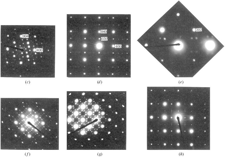
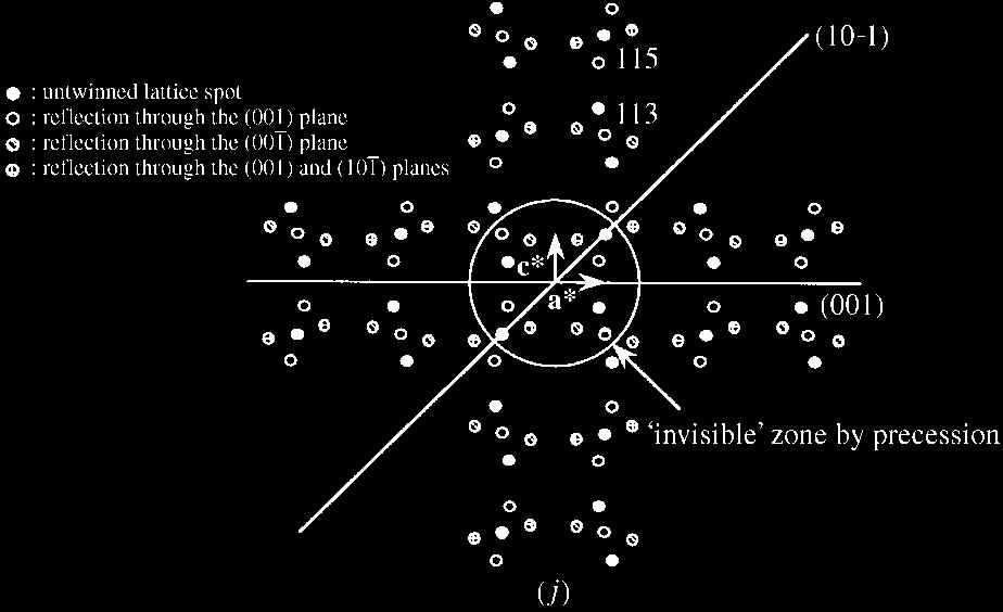
3 P. TABARY AND C. SERVANT 255 Table 1. Re ection conditions for the different choices of deformed cells Corresponding re ections in the orthorhombic cell Corresponding re ections in the monoclinic cell Cubic re ections Choice 1 Choice 2 Choice 3 Choice 4 h h h00 h00, 0k0, 0l , 00h h00, 0k0, 00l h h 2 2 0, 00h hhh hhh h0h, 0hh hhh, hhh h0h, h0h, 0hh using 11 re ections of the substructure. It could be concluded that the substructure re ections of the ' 0 phase (in sample 6), having a mean composition of 11 mol% AlN, can be interpreted using a cell, labelled (1), derived from the starting f.c.c. cell (o), having a monoclinic distorsion [non-conventional face-centredmonoclinic cell, with parameters a 1 ; b 1 ; c 1 ; 1 ˆ 7: ; 7: ; 7:8351 (8) A Ê, (11), V 1 ˆ 497:35 (14) A Ê 3, with standard uncertainties (s.u.'s) in parentheses]. In sample 5, which is two-phased (' 0 + ), the parameters of the ' 0 phase, having an average AlN content of 18 mol%, were very slightly different: a 1 ; b 1 ; c 1 ; 1 ˆ 8:000; 7:940; 7:8445 A Ê, The c (1) value was veri ed both by X-ray (7.844 A Ê ) and neutron diffraction (7.845 A Ê ) analysis. The accuracy of the b (1) and (1) constants is less satisfactory due to an insuf cient number of non-overlapping re ections Extinctions and satellites. By examining the indexing table of the powder diagram, it is seen that the re ections attributed to the substructure obey the conditions h l ˆ 4n [de ned in cell (1)]; e.g. re ections (400) (1) and (004) (1). This fact is also found for the electron diffraction pattern shown in Fig. 1(d), where b 1 is materialized by the presence of superstructure re ections (0 0 4n 2 0 0) having a low [(020) (1) ] or very low [(040) (1), (060) (1) ] intensity. The satellites of the extinctions are present on the precession, Weissenberg and transmission electron diffraction patterns. The modulation vector is situated in the a 1 ; c 1 reciprocal plane. On the X-ray diffraction diagrams, we observe only the satellites of degree 1 of the modulation (Fig. 1i), whereas on the electron diffraction patterns, satellites of higher degree are observed (Fig. 1c). The modulation vector can be expressed as m 1 ˆ m 1 a 1 m 3 c 1, and the re ections of the reciprocal space are given by Q 1 ˆ H 1 q 1, where Q 1 is the re ection, H 1 is the Bragg vector of the fundamental peak and q 1 ˆ nm 1 is the modulation vector of degree n (entire). The satellites of the fundamental extinctions h l ˆ 4n 2 and re ections h l ˆ 4n have respectively an odd n ˆ 1; 3... and even n ˆ 2; 4... degree. As an example, note in Fig. 1(d) the double spots around the extinctions 4n 2 0 4n Š 1, which are satellites with degree 4 of the re ections 4n 2 0 4n Š 1 ; they indicate that the vector a 1 is situated in the section plane Twinning. Twinning is certainly due to anisotropic stresses developing during the cooling of the sample and related to three different thermal expansion coef cients. Twinning relaxes the structure, giving rise to a pseudo-cubic cell. It is also possible that some twins are created during the mouldering of the sample to obtain the very ne powder required for examination by transmission electron microscopy (TEM). The X-ray diffraction examination by the precession method of two `single crystals' of the ' 0 phase has shown that the (001) and (101) planes of cell (1) are twin planes (Figs. 1a, 1b, 1i and 1j). The twinning explains the splitting in the two of the h0hš 1 re ections. The combination of the two twinnings provokes the splitting in two of the h00š 1 re ections and the narrow enlargement of the 00lŠ 1 and h0hš 1 re ections (see also Fig. 1g). On the contrary, the (100) (1) and (101) (1) planes are not twin planes because otherwise the 00lŠ 1 and h0hš 1 re ections would really be split in two. By TEM, both the twinning with the splitting in two of the h0hš 1 and not of the h0hš 1 re ections (Fig. 1f), and the (001) (1) twinning with the splitting in two of the h00š 1 but not of the 001Š 1 re ections were observed (Fig. 1e). On the contrary, the (101) (1) and (100) (1) twinnings were not observed. The (001) (1) twinning has a low shear ratio with an associated translation of 0.03h (h being the distance to the twin plane), in contrast to the twinning with an associated translation of 2h. The (001) (1) and twinnings often form a tangled net but they do not seem to start together (Figs. Fig. 1. Reciprocal lattice sections of the ' 0 -AlON phase. (a) Precession pattern of the twinned planes a ; c a ; b c ; b, cell (1). (b) Schematic interpretation of the precession pattern (a) of the plane a ; c, cell (1) twinned by re ection through the (001) (1) and planes. (c) Electron diffraction pattern of the plane a ; c, untwinned, cell (1). (d) Electron diffraction pattern of the plane a ; b, untwinned, cell (1). (e) Electron diffraction pattern of the plane a ; c, cell (1) with (001) (1) twinning. ( f ) Electron diffraction pattern of the plane a ; c, cell (1) with twinning. (g) Electron diffraction pattern of the plane a ; c, cell (1) with (001) (1) and twinnings. (h) Electron diffraction pattern of the plane a ; b, cell (1) with (110) (1) twinning. (i) Precession pattern of the twinned planes hll lkl hkl, cell (1). (j) Schematic interpretation of the precession pattern (i) of the hll plane, cell (1), twinned by re ection through the (001) (1) and planes.

4 256 CRYSTALLINE AND MICROSTRUCTURE STUDY OF THE Al±N±O SYSTEM. II 2 and 3). In fact, generally, a primary twinning can be observed with large and parallel twinned domains having a width and a length equal to about 300 nm and 2 mm, respectively. Inside these domains, subtwins with a narrow width (about 50 nm) appear; they result from the development of the second twinning if the primary twinning was (001) (1) (or vice versa). If the (001) (1) primary twinning occurs, the secondary twinning implies a strong distorsion of the primary twins, so these twins rst propagate in length with a very narrow width. Due to the incoherency of the sub-twins, third-rate twins having a length of about 50 nm form. They act as tampions between the primary and secondary twins. However, some areas enriched in plane defects remain and re ect the incoherency between domains. They appear on the projected image as clearer lines with an orientation perpendicular to the modulation vector. They appear when twinning occurs and, as well as twins, also relax the stresses. In addition, the (110) (1) twinning was revealed by TEM (Fig. 1h) but not the (011) (1) twinning. In Fig. 1(a) Fig. 2. Transmission electron micrographs showing the twin net of the ' 0 -AlON phase. (a) Bright eld showing the primary twinning (001) (1) and with plane defects perpendicular to the direction of the modulation vector m 1 (indicated by the arrow). (b) Bright eld revealing the same twin planes. (c) Dark eld showing the primary twinning and (001) (1).
5 P. TABARY AND C. SERVANT 257 the 0k0Š 1 re ections appear as dots; this fact is surprising because the (011) (1) or (110) (1) twinning ought to lead to an enlargement or a splitting in two of these spots. In fact, we frequently observed single crystals broken according to preferential orientations and in particular parallel to the crystalline planes (100) (1), (001) (1), (101) (1) and Positions of the ions. The extinctions lead to the choice of a C-centred monoclinic cell, labelled (2), having a volume V 2 ˆ 1 4 V 1 (Fig. 4a), as follows: a 2 ˆ a 1 c 1 =2, b 2 ˆ b 1 ; c 2 ˆ a 1 c 1 =4 and a 2 ; b 2 ; c 2 ; 2 ˆ 5:5550; 7:9379; 2:8204 A Ê, , V 2 ˆ 124:34 A Ê 3. In the spinel phase having the f.c.c. cell (o), the translations of the cationic lattice are a o, b o, c o, a o b o =2, a o c o =2, and b o c o =2, and those of the anionic lattice having an f.c.c. cell with a parameter equal to a o =2 are a o =2, b o =2, c o =2, a o b o =4, a o c o =4 and b o c o =4. In the non-conventional face-centred-monoclinic cell (1) of the ' 0 phase (distorsion of the spinel phase), the same translations are de ned with the indice (1) instead of (o). In cell (2) of the ' 0 phase, the base translations of the lattice are a (2), b (2), c (2) and a 2 b 2 =2. The translations c (2) and a 2 b 2 =2 are compatible with the anionic lattice of the spinel phase but not with its cationic lattice. We shall show, in the following, that the translations c (2) and a 2 b 2 =2 are in fact apparent translations due to a periodic jump T 1 ˆ c 2 in the spinel structure (variants of translation). Fig. 3. Schematic interpretation of the twin net in the ' 0 -AlON phase. (a) Twinning steps relative to the transmission electron micrograph of Figs. 2(a) and 2(b). (b) Twinning steps relative to the transmission electron micrograph of Fig. 2(c). Fig. 4. Mean crystal structure of the ' 0 -AlON phase. (a) Projection along [010] (1,2) with translation vectors and lattice points in cells (1) and (2). (b) Projection along [001] (2) with mean atomic positions in the cell (2). (c) Projection along [010] (1,2,3) with mean atomic positions and limits of the D domain.
6 258 CRYSTALLINE AND MICROSTRUCTURE STUDY OF THE Al±N±O SYSTEM. II Initially, a neutron diffraction spectrum of the ' 0 phase was optimized in order to determine the mean positions of the Al 3 ions. The anions were rst localized in their ideal spinel positions and the satellite re ections of the ' 0 phase were modelled using the pro lematching method (Rodriguez, 1994). For a C-centred monoclinic cell, three space groups can be used for the optimization: C2 (space group No. 5), considering symmetry versus the twofold axis, with a general multiplicity of 4; Cm (space group No. 8), considering symmetry versus the (010) plane, with a general multiplicity of 4; C2/m (space group No. 12), considering symmetry versus the twofold axis and the (010) plane, with a general multiplicity of 8. Space group No. 5 was chosen. The anionic lattice of cell (2) is described with eight sites having coordinates (0, 0, 0), (1/2, 0, 0), (1/4, 1/4, 1/2), (3/4, 1/4, 1/2), and these coordinates translated by a 2 b 2 =2. As for the cationic lattice, three Al 3 ions were rst positioned in cell (2); that is in fact six sites by considering the translation a 2 b 2 =2. Each Al 3 ion had an occupation number equal to 1, either in an octahedral or a tetrahedral site. This hypothesis was unsatisfactory. Finally, only one atomic combination (Figs. 4b and c) permitted the calculation of correct intensities for the (111) (1), (311) (1) and (220) (1) re ections with an extinction for (020) (1) : Al 3 in the octahedral sites having coordinates (0, 1/4, 0), (1/4, 0, 1/2) and (1/4, 1/2, 1/2) with respective occupation numbers 1.0, 0.5 and 0.5; Al 3 in the tetrahedral sites having coordinates (1/2, 1/8, 1/2) and (1/2, 3/8, 1/2) with respective occupation numbers 0.5 and 0.5. In cell (2), by taking into account the respective occupation numbers of the Al 3 ions in their respective octahedral and tetrahedral sites, the octahedral cation/ tetrahedral cation ratio is found to be equal to 2, as in the spinel structure [cell (o)] and in the ' 0 deformed monoclinic spinel structure [cell (1)]. In the spinel structure, cell (o), or in the ' 0 structure, cell (1), the Al 3 ions in tetrahedral sites have nearestneighbour cations located in octahedral sites at distances of a, because X o ˆ X 1 ˆ 1=8; 1=8; 3=8Š (see Fig. 6 in the rst paper of this series, by Tabary & Servant, 1999). The Al 3 ions in octahedral sites have, as nearest-neighbour cations, other Al 3 ions in octahedral sites at distances of a because X o ˆ X 1 ˆ 1=4; 1=4; 0Š, and four ions in tetrahedral sites at a. Two occupied tetrahedral sites are at distances of a, a, a or a. In Fig. 4(b), corresponding to the optimized cell (2) of the ' 0 phase, two types of Al 3 ions, labelled 1 (located in tetrahedral and octahedral sites) and 2 (located in tetrahedral and octahedral sites) are distinguished on the plane with z (2) constant; each ion has an occupation number of 0.5. In the following, the distance between two positions is given both in cell (2) and in the deformed original spinel cell (1) by using the coordinate-transformation matrix x 1 1=2 0 y 1 A A@ x 2 y 2 A: z 1 1=2 0 1=4 z 2 By taking into account the occupation number of each position, it is easy to verify that cell (2) contains eight anions, four octahedral sites and two tetrahedral sites. In addition, we have calculated that the distances between the tetrahedral and octahedral sites X 2 ˆ 1=4; 1=8; 0Š, i.e. X 1 ˆ X 0 ˆ 1=8; 1=8; 1=8Š or a, are too short for these sites to be simultaneously occupied on the same plane (z (2) constant); see, for example, in Fig. 4(b) the tetrahedral site (labelled 1) with coordinates (1/2, 1/8, 1/2) (2) and the octahedral site (labelled 2) with coordinates (1/4, 0, 1/2) (2). Thus, the sites labelled 1 and 2 have been separated and we have de ned respectively the plane P 1 (at z (2) constant) containing only the Al 3 ions labelled 1, and the plane P 2 (at z (2) constant) containing only the Al 3 ions labelled 2. An alternation of the P 1 and P 2 planes has therefore been de ned along the c (2) direction (Fig. 4c). In the same P 1 or P 2 plane, it can be calculated that: (i) the shortest distance between two occupied octahedral sites is a because X 2 ˆ 1=2; 0; 0Š, i.e. X 1 ˆ 1=4; 0; 1=4Š, as in the spinel; (ii) the shortest distance between an occupied octahedral site and an occupied tetrahedral site is a because X 2 ˆ 1=4; 3=8; 0Š, i.e. X 1 ˆ 1=8; 3=8; 1=8Š, as in the spinel; (iii) the shortest distance between two occupied tetrahedral sites is a because X 2 ˆ 1=2; 1=4; 0Š, i.e. X 1 ˆ 1=4; 1=4; 1=4Š, as in the spinel Hypothesis 1. First, it can be supposed that the modulation allows the passage of a D 1 variant containing the planes of P 1 type to a D 2 variant containing the planes of P 2 type as follows: D 1 P 1 ; P; P 1 ; P;... ; P 1! D 2 P 2 ; P; P 2 ; P;... ; P 2! In a variant D 1 (or D 2 ), the shortest distance between two occupied tetrahedral sites, for example the rst [with coordinates (1/2, 1/8, 1/2) expressed in cell (2)] in plane P 1 at z = constant, and the second [with coordinates (1/2, 1/8, 3/2) expressed in cell (2)] in plane P 1 at z = (constant + 1), would be equal to X 2 ˆ 0; 0; 1Š, i.e. X 1 ˆ 1=4; 0; 1=4Š or a. Such a situation is not observed in the spinel for which the shortest distance between two occupied tetrahedral sites is a. In addition, inside a variant, the structure factor of the re ection would be zero. In fact, F 1 ˆ exp 2 0 exp 2 1=2, because 111 the scalar product of c (2) [expressed in cell (1)] by is equal to 1=4; 0; 1=4 111 ˆ 1=2. Two successive P 1 planes belonging to a variant D 1 would
7 P. TABARY AND C. SERVANT 259 therefore be in antiphase and the satellites would have no intensity because the fundamental peak would have no intensity, which is not in agreement with the experimental results. So hypothesis 1 is not satisfactory Hypothesis 2. Inside a variant, the real cell is doubled, having the parameter c 3 ˆ 2c 2, the P 1 plane in z 3 ˆ 1=4 and the P 2 plane in z 3 ˆ 3=4. The c (2) translation is then a translation variant, T 1, which allows the passage of the D 1 variant to the D 2 variant as follows: D 1 P 1 ; P; P 2 ; P! c 3 P 1 ; P; P 2 ; P! T 1 {z } spinel D 2 P 2 ; P; P 1 ; P! c 3 P 2 ; P; P 1 ; P! T 1 {z } spinel T 1 affects only the ions of which the occupation number is 1/2 after re nement of the neutron diffraction spectrum. In Fig. 4(c), the two planes P z 3 ˆ 0 ˆ P A and P z 3 ˆ 0:5 ˆ P B are shown, along with the P 1 and P 2 planes and the domain D limited by two interfaces. The structure of the domain D 1 or D 2 thus described is in fact that of the spinel because the distance between two occupied tetrahedral sites is equal to a {see, for example, the sites with coordinates (1/2, 1/8, 1/4) and (1/2, 3/8, 3/4) expressed in cell (3) for which X 3 ˆ 0; 1=4; 1=2Š, i.e. X 2 ˆ 0; 1=4; 1Š or X 1 ˆ 1=4; 1=4; 1=4Šg. The ' 0 phase is therefore composed of spinel domains (monoclinic distorsion) which are related to one another by a translation vector T 1 ˆ a 1 c 1 =4. The re ections with odd indices can be divided into two groups, I 1 and I 2, the indices of which in cell (1) verify the relations h l ˆ 4n (and h l ˆ 4n 2) (I 1 group) and h l ˆ 4n 2 (and h l ˆ 4n) (I 2 group). In the same way, the re ections with even indices can be divided into two groups, P 1 and P 2, the indices of which verify the relations h l ˆ 4n 2 (and h l ˆ 4n 2) (P 1 group) and h l ˆ 4n (and h l ˆ 4n) (P 2 group). The T 1 translation induces differences in phase calculated from the scalar product T 1 g i as follows: T 1 ˆ 2T 1 g i, with g i the reciprocal vector corresponding to the re ection i. For the I 1 re ections, the indices of which are 4n 1; k; 1 1, T 1 ˆ 2 n 1=2 ' ; for the I 2 re ections, the indices of which are 4n 1; k; 1 1, T 1 ' 0; for the P 1 re ections, the indices of which are 4n 2; k; 0 1, T 1 ' ; for the P 2 re ections, the indices of which are 4n; k; 0 1, T 1 ' 0. For a sequence of domains D 1! T 1 D 2! T 1 D 3 ˆ D 1 the total translation vector is 2T 1 ˆ 1=2; 0; 1=2Š of the spinel [cell (o)] or of the ' 0 phase [cell (1)] and the induced differences in phase correspond to: (D 1 ) (D 2 ) D 3 2T 1 ˆ D 1 I 1 re ections: 0 0! extinction of the fundamental, modulation order 1 I 2 re ections: ! presence of the fundamental, no modulation P 1 re ections: 0 0! extinction of the fundamental, modulation order 1 P 2 re ections: ! presence of the fundamental, no modulation The extinctions and the modulations of the ' 0 phase are thus found Re nement of the mean substructure Prior knowledge of the structure (the same as that of the spinel phase) in each variant of the ' 0 phase, described above, was necessary in order to re ne the mean substructure of the ' 0 phase. In the spinel cell, the anions do not occupy the ideal positions (Tabary et al., 1999) and the u; v; wš o u; v; wš 1 versus this ideal position become, in the small cell of the spinel [which is equivalent to cell (3) of ' 0 1; 1; 1Š; 1; 1; 1Š; 1; 1; 1Š; 1; 1; 1Š 2; 1; 0Š; 0; 1; 2Š; 2; 1; 0Š; 0; 1; 2Š 3 : The positions and shifts of the 16 anions in cell (3) are listed in Table 2, along with the type of planes where they are situated (P A, P B, P 1 or P 2 ). From Table 2, it can be seen that in cell (2) of the ' 0 phase, the positions 1 to 4, 5 to 8, 9 to 12 and 13 to 16 are equivalent for the C2 group {translation [1/2, 1/2, 0] (2,3) and axial symmetry with respect to (O y )} and therefore four sites are suf cient to describe the anionic lattice: (0, 0, 0), (1/2, 0, 0), (1/4, 1/4, 1/2), (3/4, 1/4, 1/2). The average amount of vacancies in the cationic lattice is equal to 8.7% [i.e % = 2.1 vacancies per cell (1) of the spinel]; this value is calculated from the composition of the sample having 14.7 mol % AlN]. Contrary to the case of the spinel in which the vacancies are only situated in the octahedral sites (see Tabary et al., 1999), in the case of the ' 0 phase, three sites
8 260 CRYSTALLINE AND MICROSTRUCTURE STUDY OF THE Al±N±O SYSTEM. II Table 2. Positions of the anions and their shifts in the smaller cell of the Anion n to n + 1 x n ˆ x n 1 y n ˆ y n 1 z n, z n n 1 2@x n @x 2@x 1 to , 1/ / 1 P A =P B 3 to 4 1/2 1/2 0, 1/ /+1 P A =P B 5 to 6 0 1/2 0, 1/ /+1 P A =P B 7 to 8 1/2 0 0, 1/ / 1 P A =P B 9 to 10 1/4 1/4 1/4, 3/4 1 1/+1 0 P 1 =P 2 11 to 12 3/4 3/4 1/4, 3/4 1 +1/ 1 0 P 1 =P 2 13 to 14 1/4 3/4 1/4, 3/ / 1 0 P 1 =P 2 15 to 16 3/4 1/4 1/4, 3/4 +1 1/+1 0 P 1 =P 2 Occupancy (octahedral, P A;B ) (%) Table 3. Re ned neutron diffraction data from a spectrum obtained with diffractometer G4.1 Occupancy (octahedral, P 1;2 ) (%) Occupancy (tetrahedral) (%) Anion position x 1 ˆ y 1 ˆ z 1 R Bragg (%) are possible for the vacancies: octahedral on the P A, P B planes, denoted P A;B type, or on the P 1, P 2 planes, denoted P 1;2 type, and tetrahedral. The re nement of the mean substructure of the ' 0 phase was performed in cell (2). As each variant of the ' 0 phase has the structure of the spinel phase, in the case of the anions of the ' 0 phase (four equivalent positions) only one parameter of position was re ned. This parameter, x ˆ x and the occupation number of the sites have been re ned by using a neutron diffraction spectrum recorded using the diffractometer G4.1. The re ned data for cell (2) are given in Table 3; the re ned position of the anion is given in cell (1) in order to compare it with the re ned position of the anion (x ˆ y ˆ z ˆ 0:25676) for the spinel phase given in the rst paper (Tabary & Servant, 1999). Note rstly that the re ned occupation number of the octahedral sites in the P 1;2 planes is lower than in the P A;B planes, which signi es that, on average, there are more vacancies in the planes of P 1;2 type than in those of P A;B type, and secondly that the tetrahedral sites are entirely occupied. In addition, the anions are slightly shifted from their ideal position (x 0 ˆ y 0 ˆ z 0 ) ˆ 0: Compared to G4.1, the diffractometer 3T.2 allows the observation at high angles of a more important number of re ections. The fundamental re ections, which are related to the anions, are intense and allow a good optimization of the Debye±Waller parameters of the ' 0 phase, despite the perturbations due to its satellites having a lower intensity. In Fig. 5, the experimental and calculated spectra and the difference pro le for sample 6 are shown for the cases of the two types of diffractometer. The use of the isotropic thermal motion parameters is not able to explain the important differences in intensity for re ections having the same structure factor. By introducing anisotropic parameters ij, a better re nement was obtained. In order to limit the number of unknown parameters introduced, the same ij was used for the anions and cations and the terms 12 and 23 Fig. 5. Neutron diffraction spectra of sample 6 (slowly cooled from melting) recorded with two types of spectrometer in order to scan different angle ranges: (a) G4.1 spectrometer; (b) 3T.2 spectrometer.
9 P. TABARY AND C. SERVANT 261 Table 4. Re ned thermal motion parameters for the ' 0 phase i = 1, j = 1 i = 2, j = 2 i = 3, j = 3 i = 1, j = 3 ij B ij (A Ê 2 ) U ij (A Ê 2 ) were xed at 0. The usual anisotropic terms for cell (2) are given by the following equations: B ij ˆ 4ja i ka j j ij ; 1a U ij ˆ ja i ka j j=2 2 ij : 1b The U ij terms represent the values of the square mean amplitude (in A Ê 2 ). The U ij and B ij terms have the advantage that they are independent of the parameters chosen for the cell (Stout & Jensen, 1968). The re ned thermal motion parameters for the ' 0 phase are listed in Table 4 (with R Bragg ˆ 6:39%). The temperature factor of the plane (hkl) in the cell (a ; b ; c ) is then exp 2 2 U 11 h 2 a 2 U 22 h 2 b 2 U 33 l 2 c 2 U 12 hka b U 13 hla c U 23 klb c Š: 2 The thermal motion in the (010) (1,2) plane can be calculated as a function of the angle between the considered direction and the axis (100) (2) by using B xz ˆ B 11 cos 2 B 33 sin 2 B 13 cos sin : 3 The graph of B xz ˆ f (Fig. 6) shows an important anisotropy in the (010) (1,2) plane: the thermal motion is maximum for = 142, with B xz ˆ 1:066 A Ê 2, and minimum for = 52, with B xz ˆ 0:714 A Ê 2. Whatever, the thermal motion is higher in the (010) (1,2) plane than along the (010) (1,2) direction (B 22 ˆ 0:385 A Ê 2 ). The thermal motion is therefore maximum in the plane Fig. 6. Plot of B xz ˆ f for the ' 0 -AlON and -AlON phases. (010) (1,2) for a direction close to the perpendicular to the modulation vector q. In fact, these thermal motion parameters also take into account the badly de ned positions in the cell, possibly in relation to the modulation. It can be thought that the D 1 and D 2 domains are slightly translated with respect to each other, which would lead to a shifting of the (100) (2) and (001) (2) planes; this may be more important for (100) (2) than for (001) (2) Modulation vector as a function of composition Two techniques allow the determination of m 1 and m 3. Firstly, observation of the modulation of order 1 on the precession patterns (strate 1) (see for example Fig. 1i) and of any order on the electron diffraction patterns (see for example Fig. 1c). This two-dimensional technique allows a good direct determination of m 1 and m 3. Secondly, determination of the position of the satellites on a powder diagram obtained with a Guinier camera and by using a standard and the optimization of the m 1 and m 3 parameters by the least-squares method. This latter technique is more precise than the former and leads to m 1 ˆ 0:1585a 1 0:557c 1 and kmk 1 ˆ 13:66 A Ê : Table 5 shows the good agreement between the experimental and calculated positions of the re ections, expressed as d (A Ê ) and d calc (A Ê ), respectively. The calculated angle between m 1 and c 1 is This angle can be checked on the electron diffraction pattern shown in Fig. 1(c), where the satellites to the order 2 are visible. In fact, the straight line which joins the vectors and makes an angle of with the vector (c 1 axis). By joining these two spots and measuring the deviation made by each line of satellites versus this straight line, the angle between m 1 and c 1 can be measured. On a magni ed pattern, ' 3 is measured, so = The obtained angle is near the calculated one (within 0.4 ). Bassoul et al. (1976) found m 1 ' 103Š =5:5 ˆ 0:182a 1 0:545c 1 for the ' 0 phase having a composition ranging between 20 and 15 mol% AlN and presenting diffuse superstructure re ections due to the narrow size of the domains. As mentioned before, m 1 is not a fraction of the vector 103Š because the angular deviation is 3. However, we shall see that this deviation tends to decrease for a ' 0 phase enriched in nitrogen.
10 262 CRYSTALLINE AND MICROSTRUCTURE STUDY OF THE Al±N±O SYSTEM. II Table 5. Comparison of the experimental and calculated positions of the re ections for the ' 0 phase Fundamental (hkl) indices expressed in cell (1) Order of the satellite d (A Ê ) s.u. (10 4 A Ê ) d calc (A Ê ) Table 6. Experimental and calculated 2 angles for the ' 0 phase ( = A Ê. The position 2 = 0 of the diffractometer was also re ned. Fundamental (hkl) indices expressed in cell (1) Order of the satellite (n) calc ( ) (sample 6) meas ( ) (sample 5) calc ( ) (sample 5) On the neutron diffraction spectrum obtained for sample 5, some satellite lines of the ' 0 phase ; ; ; ; Š, obtained after a procedure of separation of overlapping peaks, are shifted with respect to those recorded for sample 6, and the angular spacing of the sets ; and ; has increased. Therefore, the modulation vector changes with composition. By using the parameters given in x 2.1, the calculated modulation vector is m 1 sample 5 ˆ 0:1730 0:0010a 1 0:5535 0:0010c 1 and kmk ˆ 13:64 A Ê : The experimental and calculated 2 angles are presented in Table 6. The m 1 component has increased and the m 3 component has slightly decreased, while the norm is constant. The angle between m 1 and the c 1 axis is 17.0 and the modulation vector rotates 1.4 in the reciprocal plane a 1 ; c 1, away from c 1. On the neutron diffraction patterns, the satellites of order 1 of the fundamental re ections, which are in fact extinctions, exhibit equivalent intensities to those of the re ections having the same structure factor. This con rms that the modulation is mainly due to Al 3 ions. The satellites of order 2 have weak intensities. The most visible are the satellites with d = 6.80 AÊ Observation of the antiphase domains The D 1, D 2 antiphase boundary domains have been observed with the help of HRTEM (Tabary & Servant, 1999). Here we present in Fig. 7(a) as an example a high resolution micrograph having a [001] (1) zone axis. A brief schematic interpretation is given in Fig. 7(b). The (400) (1) and (040) (1) planes with a separation of 1.97 A Ê (to the limit of resolution of the microscope used) are visible, but not the superstructure related to (020) (1), due to its intensity being too low. The (440) (1) planes are not suf ciently separated to be observed. Note the existence of lattice fringes corresponding to the (220) (1) plane despite the extinction of the spot. In this area, the translation T 1 ˆ 1=4; 0; 1=4Š 1, which causes the extinction of the spots (220) (1), projects along T 0 1 ˆ 1=4; 0Š 1. The light and intense dots make a square net of translation [1/4, 1/4], which corresponds to the tetrahedral site lattice which gives rise to the intensity of the (202) (1) re ections of the spinel. Three types of zones are observed: the net formed by the light dots described above (D 1 domain); that formed by the translation of this net by [ 1/4, 0] (1) (D 2 domain); and the (D 1 D 2 ) mean domain, with disappearance of the lattice fringes related to (220) (1). Perpendicularly to the projection T 0 1, the modulation vector m 1 ˆ 0:158a 1 0:557c 1 becomes m 0 1 ˆ 0:557c 1 with km 0 1 k ˆ 1:79c 1 ˆ 14:4 A Ê ; consequently, there is an alteration of domains D 1 and D 2, each 7.15 A Ê, perpendicularly to the section plane. In reality, the thin foil studied may have a more important thickness, but it seems possible to have an average over D 1 and D 2 not equal to zero, which would explain the existence of the contrast of D 1, D 2 or no contrast. A calculation of the simulation of the contrast would be able to re ne the proposed interpretation. Furthermore, it can be noted that the fracture of the crystal occurs preferably along a (010) (1) type plane Superstructure with vacancies Cell with vacancies. The re ection (020) (1) of the ' 0 phase presents a weak intensity, as shown both on the electron diffraction pattern (see Fig. 1d) and on the neutron diffraction diagrams. On the contrary, in the case of the -AlON spinel, this intensity is zero. This low intensity is due to the different occupation number of
 c(' 0 ) (mol% AlN) n v P 1;2 [equation (6)] n v P 1;2 (neutron diffraction) n v total")
11 P. TABARY AND C. SERVANT 263 Table 7. Comparison of the number of vacancies on the P 1;2 planes with the total number of vacancies m 1 ; c 1 ( ) c(' 0 ) (mol% AlN) n v P 1;2 [equation (6)] n v P 1;2 (neutron diffraction) n v total [equation (4)] ± 1.94 the cations Al 3 in the sites of the P A;B and P 1;2 planes of the ' 0 phase Positions of the vacancies. We have shown in x2.1.4 that the ' 0 phase is composed of domains, each having the crystalline structure of the spinel phase (succession of planes P 1 ; P A ; P 2 ; P B ; P 1 ; P A ; P 2 ; P B ;... along the c (3) axis), but translated with respect to one another by the T 1 vector, which changes the con guration of a plane of P 1;2 type at each interface because the positions labelled 1 and 2 in Fig. 4(b) cannot be simultaneously occupied on the same plane of P 1;2 type. We can imagine that at each antiphase interface P 1! P 2! P 1 ;... ; at least one cationic vacancy is present on each plane of P 1;2 type. Furthermore, in x2.2, we have shown that the vacancies are only situated in the octahedral sites in the P A;B and P 1;2 planes and that their amount is higher in the planes of P 1;2 type than in the planes of P A;B type. Fig. 7. HRTEM of the ' 0 phase. (a) Bright eld. (b) Schematic interpretation of the contrast. The electroneutrality of the phases imposes the total number of vacancies per cell (1), 200 x0 n v ˆ x 0 where x 0 is mol% AlN. The mean distance d between two vacancies, each one being situated on a plane of P 1;2 type of the interface, is given by the relation (see Fig. 4c) a m1 c d ˆ with ' arctan 5 2 cos sin m 3 a and n v P 1;2 ˆ abc 2jm j db ˆ cos sin 4c jmj with a, b, c the parameters of cell (1). In Table 7, the number of vacancies on the P 1;2 planes, n v P 1;2, at the interfaces calculated with equation (6), is compared both with the total number of vacancies determined by neutron diffraction peak-pro le re nement, and with the total number of vacancies determined by equation (4). The comparison of n v total [equation (4)] with n v P 1;2 [equation (6)] obtained in the hypothesis of the presence of only one vacancy on each plane of P 1;2 type at each interface of the ' 0 phase, shows that it is probable that there are no other vacancies on the planes of P 1;2 type at the interfaces and a fortiori inside the D 1 and D 2 variants. Furthermore, the remainder of the vacancies [difference between n v total and n v P 1;2 ] are probably situated at the interfaces in the planes of P A;B type (the amount of which has been calculated to be lower than that of the P 1;2 type). Note that the distance d between two vacancies, that is the mean distance between two interfaces, is equal to about 6.3 A Ê (Fig. 4c); this is half of the modulation vector length Composed displacement/composition modulation The intensities of the satellites of order 1 of ' 0 (like those of the phase) appear dissymetrical in the X-ray spectra (see the precession diagram shown in Figs. 1i and 8), but not, in general, in the neutron diffraction spectra (Table 8). For a modulated structure, either in composition only or in displacement only, the two satellites of order n of a re ection have very close intensities (Pan, 1992). This fact is not observed in the present work, which implies the existence of a double modulation in composition and 6
12 264 CRYSTALLINE AND MICROSTRUCTURE STUDY OF THE Al±N±O SYSTEM. II in displacement. The presence of the interfaces would be able to cause a modulation in displacement of the cations of the order 2 and a priori not of the order 1 (displacement too important), and, in addition, if the Al 3 ions were the only ones responsible for the modulation, these ratios ought to be identical in X-ray and neutron diffraction. In fact, the translation T 1 between the D 1 and D 2 variants corresponds to a small shifting of the anions with a period of order 1. In the general case, when a modulation in displacement is involved, the position of an atom s in cell j can be expressed as R s ˆ R 0 j r 0 s A s sin 2qR 0 j s 7 where R 0 j is the position of cell j, r 0 s is the position of the atom s in the origin cell, A s is the vectorial amplitude of the modulation associated with the rst harmonic, and s is the phase associated with the rst harmonic of the atom s in the origin cell. The anions 1 to 8 are translated by 4@xc 3, i.e. A 1 8 ˆ 2@xc 3 with 1;4;6;7 ˆ =2 and 2;3;5;8 ˆ =2, and the anions 9 to 16 by 2:@xb 3, i.e. A with 10;11;13;16 ˆ =2 and 9;12;14;15 ˆ =2 (see Table 2). As the shifts are limited, the scattered amplitude for the diffraction vector Q is A Q ˆ P 2QA s f s Q exp i s s exp i2qr 0 s ˆ f O;N Q P 2QA s exp i s O;N exp i2qr 0 s : 8 For a modulation in composition, an order parameter S, with S = 1 corresponding to the total order and S = 0 for the complete disorder, is de ned. The diffuse atomic factor of the s atom in the j cell is given by f s Q ˆ f s Q 1 S cos 2qR 0 j ' s Š 9 where ' s is the phase associated with the s atom in the origin cell. The cationic sites 1 and 2 of the P 1;2 planes each have a mean occupation number of 0.5. The occupation number is 1 or 0 as a function of the considered plane and domain, and the modulation in composition with an order parameter equal to S = 1 can be modelled with f s Q ˆ 1 2 f Al Q 10 and the scattered amplitude for a diffraction vector Q, A Q ˆ S 2 P s f s Q exp i' s exp i2qr 0 s ˆ 1 4 f Al Q P exp i' s exp i2qr 0 s : 11 Al with ' s ˆ 0 for cations of type 1 on the P 1 planes of type 2 on the P 2 planes of D 1, and ' s ˆ for cations of type 2 on the P 1 planes and of ype 1 on the P 2 planes of D 1. For a composed modulation in displacement and composition, the scattered amplitude for the diffraction vector Q is A Q ˆ P f s Q fj 1 2QA s S=2 J 2 2QA s s exp i ' s s Š S=2 J 0 2QA s exp i ' s s Šg exp i2qr 0 s 12 where J i is the Bessel function of order i. Thus A Q ˆ f O;N Q P 2QA s exp i s exp i2qr 0 s O;N 1 4 f Al Q P Al exp i' s exp i2qr 0 s 3 ˆ The structure factors of the cations and anions are not proportionately the same in the case of the X-ray and neutron diffractions. This fact can explain the different intensity ratio of the satellites +q and q when using the two types of radiation. The same result has been obtained for the phase, as will be seen in the next section. Fig. 8. Schematic (hll) strate, with the intensity of the satellites of the order 1 of the ' 0 phase. 3. The d phase 3.1. Structural modelling Cell parameters. The cell parameters were determined using two samples, rapidly cooled (700 K min 1 ) and containing a mean composition of 3.5 mol % AlN; the rst sample (7A) was slightly depleted in nitrogen compared to the second (7B). Samples 7A and 7B contain both the and the
13 Fundamental (hkl) expressed in cell (1) P. TABARY AND C. SERVANT 265 Table 8. Intensity of the satellites of order 1 of the ' 0 phase Order of the satellite I obs (X-ray) Observed structure factor (X-ray) I obs (neutron) Observed structure factor (neutron) corundum phases. The composition of the phase is equal to 5 and 9 mol % AlN in samples 7A and 7B, respectively. The determination of the extinctions needed both X-ray diffractometry and TEM data. The parameters were calculated after using corundum as a standard because the amount of this phase in the samples was considered important. The study of the precession diagrams and of the electron diffraction patterns showed that the phase is always twinned; this fact is in agreement with the literature. The large cell (1) of is deformed by an orthorhombic distorsion with a o, b o, c o respectively parallel to a c, b c, c c, with the indice c for cubic. For sample 7A, a; b; c ˆ 7:963; 7:932; 7:814 A Ê ), and for 7B, a; b; c ˆ 7:963; 7:932; 7:816 A Ê ) Extinctions and satellites. The diffraction lines of the spinel structure which do not obey h l ˆ 4n are absent, which excludes lines with odd indices and lines with even indices for the extinctions of ' 0. The presence of the (202) (1) re ections (Fig. 9b) and of the (242) (1) re ections (Fig. 9g), as well as the absence of the (220) (1) re ections (Fig. 9d), (224) (1) (Fig. 9f) and (022) (1) (Fig. 9a), have been shown by electron diffraction. The structure of the phase can be described in an orthorhombic cell, (2), having two (B) centred faces, with parameters equal to half the parameters of the cell (1), with V 2 ˆ V 1 =8 (see Fig. 10a). In agreement with the work of Michel & Huber (1970), it is easy to verify in Fig. 1(i) that the modulation vector m 1 is parallel to the reciprocal direction corresponding to the shortest interplanar distance, i.e. c 1 (or c 2. The satellites of the fundamental re ections have an even order and a weak intensity. The satellites of the extinctions having even indices are even with an intense order 2, and the satellites of the extinctions having odd indices are odd with an intense order Position of the atoms and variants. Let us suppose rst that the ratio of octahedral cations to tetrahedral cations is identical (2:1) for the two phases - AlON and -AlON, and secondly that the anionic lattices are the same in the two phases; P cell (2) contains eight tetrahedral sites with occupancy tn ˆ 8 8=64 ˆ 1, and four octahedral sites with P occupancy on ˆ 4 16=32 ˆ 2. By taking into account the translation (1/2, 0, 1/2) (2) of the centred cell, half of the sites are equivalent and occupancy t 1 occupancy t 2 occupancy t 3 occupancy t 4 ˆ 1=2, with occupancy t 1 ˆ occupancy t 5 ; occupancy t 2 ˆ occupancy t 6 ;... ; and occupancy o 1 occupancy o 2 ˆ 1, with occupancy o 1 ˆ occupancy o 3 ; occupancy o 2 ˆ occupancy o 4 (t and o represent tetrahedral and octahedral, respectively). The intensity of the (101) (2) re ection [i.e. (202) (1) ] is identical to that of the (202) (1) re ection of the spinel (see Table 10), due to the totality of the tetrahedral ions but not of the octahedral ions, and therefore occupancy o 1 ˆ occupancy o 2 ˆ 1=2 and occupancy t 3 ˆ occupancy t 4 ˆ 0. As the (010) (2) re ection exhibits an intensity different from zero, the condition occupancy t 1 ˆ occupancy t 2 ˆ 1=4 is assumed (see Figs. 10b and 10c). In the same way as determined for the ' 0 phase, t 1 and t 2, separated by a distance of b (2) /2 (i.e. b 1 =4 ˆ 0:25a ), are too near to be simultaneously occupied. By comparing Figs. 4(b) and 10(c), it can be seen that the mean structure of the phase corresponds to two variants of the ' 0 phase translated by T 2 ˆ 1=4; 0; 1=4Š 1. There are twice as many tetrahedral sites in the phase, but with an occupation number half that of the ' 0 phase (0.5 for ' 0 and 0.25 for ). The translation T 2 does not affect the octahedral cations of the P 1;2 planes, which keep an occupation number 0.5, whereas the other octahedral cations are distributed on twice as many sites with an occupation number divided by two (from 1 to 0.5). It has been shown that the satellites of the re ections with even indices which do not satisfy h l ˆ 4n have intense satellites of order 2, and so have a reciprocal periodicity of 2m 1 and a direct period which is half that of the other intense satellites. By reconsidering the groups of re ections I 1, I 2, P 1 and P 2 de ned for cell (1) at the ' 0 phase, the T 1 and T 2 translations induce phase displacements as follows: for the I 1 re ections, T 1 ˆ 2 n 1=2 ', T 2 ˆ 2 h=4 1=4 ˆ 2 h=4 1=4 ˆ 2n ' 0; for the I 2 re ections, T 1 ' 0, T 2 ' ; for the P 1 re ections, T 1 ', T 2 ' ; for the P 2 re ections, T 1 ' 0, T 2 ' 0.

 found only two variants, translated by [1/2, 0, 0] with respect to each other.")
 by X-ray techniques were systematically twinned, so he could not observe the extinctions of the (220) (1) and (022) (1) diffraction peaks, only")
14 266 CRYSTALLINE AND MICROSTRUCTURE STUDY OF THE Al±N±O SYSTEM. II If a succession of domains such as D 1! T 1 D 2! T 2 D 3! T 1 D 4! T 2 D 5 ˆ D 1 is assumed, the total translation vector is 2T 1 2T 2 ˆ 1; 0; 0Š 0 of the spinel and we obtain for: I 1 re ections: 0 0! fundamental extinction, modulation order 1 I 2 re ections: 0 0 0! fundamental extinction, modulation order 1 P 1 re ections: 0 0 0! fundamental extinction, modulation order 2 P 2 re ections: ! fundamental present, no modulation Lefebvre (1975) found only two variants, translated by [1/2, 0, 0] with respect to each other. This translation does not induce the extinction of any (202) (1), (220) (1) or (022) (1) re ections. In fact, the crystals studied by Lefebvre (1975) by X-ray techniques were systematically twinned, so he could not observe the extinctions of the (220) (1) and (022) (1) diffraction peaks, only visible by TEM Re nement of the mean substructure This re nement was performed from the monoclinic cell (3): a 3 ˆ a 2 c 2 =2, b 2 ˆ b 3, c 3 ˆ a 2 c 2 =2, 3 ˆ 91:068. By reconsidering Table 2, the positions 1 to 8 are equivalent for space group P2/m [symmetry with respect to the (Oy) axis and the (010) plane, i.e. a general multiplicity equal to 4], as well as the positions 9 to 16 (see Table 9). (a) (b) (c) (d) (e) ( f ) (g) Fig. 9. Reciprocal lattice sections observed by TEM of the -AlON phase. (a) Plane b ; c, untwinned, cell (1). (b) Plane a ; c, untwinned, cell (1). (c) Plane a ; c, cell (1) with (101) (1) twinning. (d) Plane a ; b, untwinned, cell (1). (e) Plane a ; b, cell (1) with (110) (1) twinning. ( f ) Plane a b ; c, cell (1). (g) Plane a 2b ; c, cell (1).
15 P. TABARY AND C. SERVANT 267 As the in uence of the anionic displacement on the present re ections is low, x was xed at The intensity of the satellites (1) of the re ection (111) (1) con rms this hypothesis. The R Bragg agreement factor was improved by introducing anisotropic factors as for the ' 0 phase. When all the vacancies were positioned on the octahedral sites o 1 and o 2, we obtained R Bragg = 1.56% (see also Fig. 11a). In Table 10, the observed and calculated (after re nement) neutron diffraction intensities of some re ections of the -AlON phase are compared. ij values are listed in Table 11 (see also Fig. 6). Lefebvre (1975) previously supposed that the vacancies were distributed in the tetrahedral sites because the (222) (1) re ection is the only one to have a purely octahedral component and does not exhibit satellites. In fact, the (222) (1) re ection belongs to the P 2 group and does not present any intense satellite independently of the vacancy distribution Modulation vector as a function of composition In sample 7A, containing 15.4 wt % -Al 2 O 3, the phase is depleted of nitrogen with an AlN composition close to about 5 mol%. In sample 7B, the more enriched nitrogen composition of the phase is about 9 mol% AlN. The re nement of the X-ray diffraction spectra of samples 7A and 7B, after standardization by corundum, allowed the modulation vector to be calculated: m 1 ˆ m 3 c 1. For samples 7A and 7B, we respectively calculated m 1 ˆ 0:313 0:0005 c 1 and m 1 ˆ 0:307 0:0005 c 1. Fig. 10. Mean crystal structure of the -AlON phase. (a) Projection along [010] (1,2,3) ; translation vectors and lattice points. (b) Projection along [010] (1,2,3) ; mean atomic positions. (c) Projection along 101Š 2 ; mean atomic positions.
16 268 CRYSTALLINE AND MICROSTRUCTURE STUDY OF THE Al±N±O SYSTEM. II Anion x 3 n Table 9. Details on the positions of the anions y 3 n z 3 n = n = n = 4@x Planes 1 to / 1 +1/ 1 P A =P B 9 to 16 1/2 1/2 1/2 1/+1 1/+1 0 P 1 =P 2 As shown in Table 12, the satellites lead to a very precise calculation of m 1 [the accuracy is average by using and , and lower with ]. In the same way as above, where we determined the modulation vector of the ' 0 phase in the two-phased ( + ' 0 ) sample, the study of the satellites of the phase, enriched in nitrogen, present in the neutron diffraction spectrum of sample 6, which is two-phased (' 0 + ), allows the calculation of m 3 = (10). On the a ; b b c plane, cell (1), corresponding to the crystal of Fig. 1(i), the distance between the intense satellite spots and corresponds to m 3 = (10). The m 3 parameter changes with the composition of the -AlON phase, as follows: for (5 mol % AlN), m 3 = 0.313, direct period 3.195c; for (9 mol % AlN), m 3 = 0.285, direct period 3.5c. Fig. 11. Neutron diffraction spectra recorded from sample 7, rapidly cooled from the melting point: (a) experimental and re ned; (b) vacancy superstructure of the -AlON phase [the peaks are indexed in cell (3)]. The present results are consistent with those of Lefebvre et al. (1973) and Lefebvre (1975), who showed that the direct modulation period varies from 3.15 to 3.50 when the composition of the -AlON phase changes from 3 to 10 mol % AlN Superstructure of vacancies Vacancy cell and type of vacancies. With the help of the neutron and electron diffraction analyses, a superstructure containing vacancies was evidenced. It has a low intensity with a period 2a (1) in the [100] direction and a period b (1) in the [010] direction (see Figs. 10a, 10b and 10d). Another cell containing vacancies (a 4 ˆ 2a 1 ; b 4 ˆ b 1 ; c 4 ˆ c 1 ) and denoted (4) can be de ned. The (hkl) re ections are observed for even l and the extinctions for odd l. In addition, we have shown the presence of 2m satellites for even l and m for odd l. The simultaneous existence of the hkl 2 and hkl 1 satellites is dif cult to observe on the electron diffraction patterns because the spots are practically superimposed. The separation of the hk0 2 and hkl 1 at low-angle neutron re ections is shown in Fig. 11(b) and Table 13. We calculate m 1 ˆ 0:313c 1. Contrary to the neutron diffraction, by using electron diffraction we observed mainly the satellite and to a lesser extent the satellite; this fact could signify that the anions contribute to the diffracted intensity. By calculating the structure factor of each re ection divided by 2.4, the total number of vacancies per cell (1), and by neglecting the variation of the Debye±Waller factors between 2 = 10 and 52, one obtains the results per cell as shown in Table 14. These `structure factors' show that the intensities of the re ections are in quite good agreement with the existence of a cell of Al 3 ions having vacancies Positions of the vacancies. The total number of vacancies per unit cell (1) is imposed by the electroneutrality of the -AlON phase: 200 x0 n v ˆ x 0 where x 0 is mol% AlN. As for the ' 0 phase, on each interface related by the translation T 1, at least one cationic vacancy is present on each P 1;2 plane. On each interface related by the translation T 2, there is at least one vacancy on each P A;B plane. There are, therefore, two vacancies for an interfacial surface: ja 1 kb 1 j. The distance between the interface planes of the domains
 (1) 101 3 ˆ 400 1 020 3 ˆ 040 1 101 3 ˆ 040 1 d (A Ê ) 2.7885 2.")
 0.89 0.")
17 P. TABARY AND C. SERVANT 269 Table 10. Observed and calculated intensities of the neutron diffraction spectrum recorded for the -AlON phase hkl 3 ˆ hkl ˆ (222) (1) ˆ ˆ ˆ d (A Ê ) I obs (total) I calc (total) Table 11. ij of the -AlON phase i = 1, j = 1 i = 2, j = 2 i = 3, j = 3 i = 1, j = 3 ij B ij (A Ê 2 ) being equal to c/(4m 3 ), the mean number of interfacial vacancies per cell (1) is n v interface ˆ 2 4m 3 ˆ 8m 3 : 15 By making the hypothesis that n v interface ˆ n v and by combining equations (14) and (15), we obtain: 200 x0 m 3 ˆ x : 16 0 In Fig. 12, the evolution of m 3 as a function of the composition of the samples studied is plotted, along with data from the literature and the value calculated with expression (16). The m 3 parameters determined by the two methods are identical: this means that the hypothesis of the distribution of vacancies on the interface is correct and that there is no other vacancy outside of these interfaces. Note that the value m 3 = 1/3 corresponds to -Al 2 O 3 (x 0 = 0 and n v ˆ 2:66), which has been described as a `pile up' of three cubic cells in the c direction (Lippens & De Boer, 1964). The bright- eld micrographs shown in Fig. 13 correspond to a [010] (1) zone axis. They were obtained by standard-resolution TEM. In Fig. 13(a), more-or-less bright domains having a size between 50 and 100 nm are observed. They correspond to translation variants (Tabary & Servant, 1999). Stacking faults on the (001) (1) planes can be distinguished; they may not be related to the superstructure with vacancies but to the existence of supplementary (001) (1) planes or missing planes in the structure. The same type of defects exists in the (100) (1) planes, but are less visible. In Fig. 13(b), a twin a; c $ c; a [twinning plane ] is visible. We veri ed that the (100) (1) planes of the (a, c) domain present a mis t of about 1 with respect to the (001) (1) planes of the (c, a) domain, which corresponds to the mis t calculated from the crystalline parameters Presence of the 2 phase The phase above corresponds to the 1 phase of the literature. It is characterized with an irrational modulation along the c (1) axis. According to Lefebvre et al. Fig. 12. Evolution of the modulation period versus the -AlON phase composition. Fig. 13. Electron micrographs of the -AlON phase. (a) Dark eld in standard-resolution electron microscopy showing variants and defects. (b) Dark eld in standard-resolution electron microscopy showing twins a; c $ c; a.
Comments on the characteristics of incommensurate modulation in quartz: discussion about a neutron scattering experiment
 65 Acta Cryst. (1999). A55, 65±69 Comments on the characteristics of incommensurate modulation in quartz: discussion about a neutron scattering experiment T. A. Aslanyan,² T. Shigenari* and K. Abe Department
research papers Calculation of crystal truncation rod structure factors for arbitrary rational surface terminations
 Journal of Applied Crystallography ISSN 0021-8898 Received 22 April 2002 Accepted 5 August 2002 Calculation of crystal truncation rod structure factors for arbitrary rational surface terminations Thomas
research papers 1. Introduction 2. Experimental E. Rossmanith, a * A Hupe, a R. Kurtz, a H. Schmidt a and H.-G. Krane b
 Journal of Applied Crystallography ISSN 0021-8898 Received 14 September 2000 Accepted 17 January 2001 Kinematical two-dimensional multiple-diffraction intensity profiles. Application to x±w scans of silicon
X-ray Diffraction. Diffraction. X-ray Generation. X-ray Generation. X-ray Generation. X-ray Spectrum from Tube
 X-ray Diffraction Mineral identification Mode analysis Structure Studies X-ray Generation X-ray tube (sealed) Pure metal target (Cu) Electrons remover inner-shell electrons from target. Other electrons
Supplementary Information
 Supplementary Information Supplementary Table 1. Atomic details for the crystal structures of silver closo-boranes. See Table 1 for further details. α Ag 2 B 10 H 10 Wyckoff x y z U / Å 2 Occ. Ag 4d 0.250
Structure and Non-linear Optical Properties of b-barium Borate
 652 Acta Cryst. (1998). B54, 652±656 Structure and Non-linear Optical Properties of b-barium Borate D. F. Xue and S. Y. Zhang* Laboratory of Rare Earth Chemistry and Physics, Changchun Institute of Applied
Geometry of Crystal Lattice
 0 Geometry of Crystal Lattice 0.1 Translational Symmetry The crystalline state of substances is different from other states (gaseous, liquid, amorphous) in that the atoms are in an ordered and symmetrical
Transmission Electron Microscopy and Diffractometry of Materials
 Brent Fultz James Howe Transmission Electron Microscopy and Diffractometry of Materials Fourth Edition ~Springer 1 1 Diffraction and the X-Ray Powder Diffractometer 1 1.1 Diffraction... 1 1.1.1 Introduction
research papers Extinction-corrected mean thickness and integral width used in the program UMWEG98
 Journal of Applied Crystallography ISSN 21-8898 Received 6 July 1999 Accepted 13 January 2 # 2 International Union of Crystallography Printed in Great Britain ± all rights reserved Extinction-corrected
Chapter 5. Effects of Photonic Crystal Band Gap on Rotation and Deformation of Hollow Te Rods in Triangular Lattice
 Chapter 5 Effects of Photonic Crystal Band Gap on Rotation and Deformation of Hollow Te Rods in Triangular Lattice In chapter 3 and 4, we have demonstrated that the deformed rods, rotational rods and perturbation
Chapter 2. X-ray X. Diffraction and Reciprocal Lattice. Scattering from Lattices
 Chapter. X-ray X Diffraction and Reciprocal Lattice Diffraction of waves by crystals Reciprocal Lattice Diffraction of X-rays Powder diffraction Single crystal X-ray diffraction Scattering from Lattices
research papers Implementation of molecular replacement in AMoRe 1. Introduction Jorge Navaza
 Acta Crystallographica Section D Biological Crystallography ISSN 0907-4449 Implementation of molecular replacement in AMoRe Jorge Navaza CNRS-GIF, LGV, 91198 Gif-sur-Yvette, France Correspondence e-mail:
Applications of X-ray and Neutron Scattering in Biological Sciences: Symmetry in direct and reciprocal space 2012
 Department of Drug Design and Pharmacology Applications of X-ray and Neutron Scattering in Biological Sciences: Symmetry in direct and reciprocal space 2012 Michael Gajhede Biostructural Research Copenhagen
addenda and errata addenda and errata Structure, odd lines and topological entropy of disorder of amorphous silicon. Correction
 addenda and errata Acta Crystallographica Section A Foundations of Crystallography ISSN 0108-7673 addenda and errata Structure, odd lines and topological entropy of disorder of amorphous silicon. Correction
A one-dimensional model for small-angle X-ray scattering from crystalline block copolymers
 Acta Crystallographica Section A Foundations of Crystallography ISSN 18-7673 A one-dimensional model for small-angle X-ray scattering from crystalline block copolymers Didier Villers Copyright International
Supplementary Figure 1: Crystal structure of CRCA viewed along the crystallographic b -direction.
 Supplementary Figure 1: Crystal structure of CRCA viewed along the crystallographic b-direction. Open arrows compare the direction and relative amplitudes of the (total) theoretical polarization vector
Courtesy of Ray Withers Electron Diffraction and the Structural Characterization of Modulated and Aperiodic Structures
 Courtesy of Ray Withers Electron Diffraction and the Structural Characterization of Modulated and Aperiodic Structures What do we mean by a modulated structure? The standard answer is a material whose
DIFFRACTION PHYSICS THIRD REVISED EDITION JOHN M. COWLEY. Regents' Professor enzeritus Arizona State University
 DIFFRACTION PHYSICS THIRD REVISED EDITION JOHN M. COWLEY Regents' Professor enzeritus Arizona State University 1995 ELSEVIER Amsterdam Lausanne New York Oxford Shannon Tokyo CONTENTS Preface to the first
Crack dynamics in elastic media
 PHILOSOPHICAL MAGAZINE B, 1998, VOL. 78, NO. 2, 97± 102 Crack dynamics in elastic media By Mokhtar Adda-Bedia and Martine Ben Amar Laboratoire de Physique Statistique de l Ecole Normale Supe  rieure,
Basic Crystallography Part 1. Theory and Practice of X-ray Crystal Structure Determination
 Basic Crystallography Part 1 Theory and Practice of X-ray Crystal Structure Determination We have a crystal How do we get there? we want a structure! The Unit Cell Concept Ralph Krätzner Unit Cell Description
SECOND PUBLIC EXAMINATION. Honour School of Physics Part C: 4 Year Course. Honour School of Physics and Philosophy Part C C3: CONDENSED MATTER PHYSICS
 2753 SECOND PUBLIC EXAMINATION Honour School of Physics Part C: 4 Year Course Honour School of Physics and Philosophy Part C C3: CONDENSED MATTER PHYSICS TRINITY TERM 2011 Wednesday, 22 June, 9.30 am 12.30
Tb 2 Hf 2 O 7 R 2 B 2 7 R B R 3+ T N
 Tb Hf O 7 7 χ ac(t ) χ(t ) M(H) C p(t ) µ χ ac(t ) µ 7 7 7 R B 7 R B R 3+ 111 7 7 7 7 111 θ p = 19 7 7 111 7 15 7 7 7 7 7 7 7 7 T N.55 3+ 7 µ µ B 7 7 7 3+ 4f 8 S = 3 L = 3 J = 6 J + 1 = 13 7 F 6 3+ 7 7
- A general combined symmetry operation, can be symbolized by β t. (SEITZ operator)
") SPACE GROUP THEORY (cont) It is possible to represent combined rotational and translational symmetry operations in a single matrix, for example the C6z operation and translation by a in D 6h is represented
SPACE GROUP THEORY (cont) It is possible to represent combined rotational and translational symmetry operations in a single matrix, for example the C6z operation and translation by a in D 6h is represented
Supporting Information
 Supporting Information Figure S1. XRD patterns of ZnGa 2 O 4, GaN, ZnO, and Ga 2 O 3. Figure S2. SEM micrographs for ZnO (A), Ga 2 O 3 (B), GaN (C), ZnGa 2 O 4 (D). Figure S3A. Raman shifts associated
Structure and Dynamics : An Atomic View of Materials
 Structure and Dynamics : An Atomic View of Materials MARTIN T. DOVE Department ofearth Sciences University of Cambridge OXFORD UNIVERSITY PRESS Contents 1 Introduction 1 1.1 Observations 1 1.1.1 Microscopic
Roger Johnson Structure and Dynamics: Displacive phase transition Lecture 9
 9.1. Summary In this Lecture we will consider structural phase transitions characterised by atomic displacements, which result in a low temperature structure that is distorted compared to a higher temperature,
PX-CBMSO Course (2) of Symmetry
 of Symmetry") PX-CBMSO Course (2) The mathematical description of Symmetry y PX-CBMSO-June 2011 Cele Abad-Zapatero University of Illinois at Chicago Center for Pharmaceutical Biotechnology. Lecture no. 2 This material
PX-CBMSO Course (2) The mathematical description of Symmetry y PX-CBMSO-June 2011 Cele Abad-Zapatero University of Illinois at Chicago Center for Pharmaceutical Biotechnology. Lecture no. 2 This material
Keble College - Hilary 2012 Section VI: Condensed matter physics Tutorial 2 - Lattices and scattering
 Tomi Johnson Keble College - Hilary 2012 Section VI: Condensed matter physics Tutorial 2 - Lattices and scattering Please leave your work in the Clarendon laboratory s J pigeon hole by 5pm on Monday of
Analytical Methods for Materials
 Analytical Methods for Materials Lesson 15 Reciprocal Lattices and Their Roles in Diffraction Studies Suggested Reading Chs. 2 and 6 in Tilley, Crystals and Crystal Structures, Wiley (2006) Ch. 6 M. DeGraef
High-Resolution. Transmission. Electron Microscopy
 Part 4 High-Resolution Transmission Electron Microscopy 186 Significance high-resolution transmission electron microscopy (HRTEM): resolve object details smaller than 1nm (10 9 m) image the interior of
SECOND PUBLIC EXAMINATION. Honour School of Physics Part C: 4 Year Course. Honour School of Physics and Philosophy Part C C3: CONDENSED MATTER PHYSICS
 A11046W1 SECOND PUBLIC EXAMINATION Honour School of Physics Part C: 4 Year Course Honour School of Physics and Philosophy Part C C3: CONDENSED MATTER PHYSICS TRINITY TERM 2015 Wednesday, 17 June, 2.30
Supplementary figures
 Supplementary figures Supplementary Figure 1. Second harmonic generation polarimetry setup: Schematic of the second harmonic generation (SHG setup used for SHG polarimetry on GeTe devices (reproduced with
3.091 Introduction to Solid State Chemistry. Lecture Notes No. 5a ELASTIC BEHAVIOR OF SOLIDS
 3.091 Introduction to Solid State Chemistry Lecture Notes No. 5a ELASTIC BEHAVIOR OF SOLIDS 1. INTRODUCTION Crystals are held together by interatomic or intermolecular bonds. The bonds can be covalent,
Crystal Structure Determination II
 Crystal Structure Determination II Dr. Falak Sher Pakistan Institute of Engineering and Applied Sciences 09/10/2010 Diffraction Intensities The integrated intensity, I (hkl) (peak area) of each powder
Solid State Spectroscopy Problem Set 7
 Solid State Spectroscopy Problem Set 7 Due date: June 29th, 2015 Problem 5.1 EXAFS Study of Mn/Fe substitution in Y(Mn 1-x Fe x ) 2 O 5 From article «EXAFS, XANES, and DFT study of the mixed-valence compound
Name :. Roll No. :... Invigilator s Signature :.. CS/B. Tech (New)/SEM-1/PH-101/ PHYSICS-I
/SEM-1/PH-101/ PHYSICS-I") Name :. Roll No. :..... Invigilator s Signature :.. CS/B. Tech (New)/SEM-1/PH-101/2011-12 2011 PHYSICS-I Time Allotted : 3 Hours Full Marks : 70 The figures in the margin indicate full marks. Candidates
Name :. Roll No. :..... Invigilator s Signature :.. CS/B. Tech (New)/SEM-1/PH-101/2011-12 2011 PHYSICS-I Time Allotted : 3 Hours Full Marks : 70 The figures in the margin indicate full marks. Candidates
research papers 656 Macchi and Coppens Scattering factors Acta Cryst. (2001). A57, 656± Introduction 2. Computational details
. A57, 656± Introduction 2. Computational details") Acta Crystallographica Section A Foundations of Crystallography ISSN 0108-7673 Relativistic analytical wave functions and scattering factors for neutral atoms beyond Kr and for all chemically important
Acta Crystallographica Section A Foundations of Crystallography ISSN 0108-7673 Relativistic analytical wave functions and scattering factors for neutral atoms beyond Kr and for all chemically important
Phonon scattering: how does it a ect the image contrast in high-resolution transmission electron microscopy?
 PHILOSOPHICAL MAGAZINE B, 1999, VOL. 79, NO. 1, 37± 48 Phonon scattering: how does it a ect the image contrast in high-resolution transmission electron microscopy? Z. L. Wang² School of Materials Science
CHEM-E5225 :Electron Microscopy Imaging
 CHEM-E5225 :Electron Microscopy Imaging 2016.10 Yanling Ge Outline Planar Defects Image strain field WBDF microscopy HRTEM information theory Discuss of question homework? Planar Defects - Internal Interface
AP5301/ Name the major parts of an optical microscope and state their functions.
 Review Problems on Optical Microscopy AP5301/8301-2015 1. Name the major parts of an optical microscope and state their functions. 2. Compare the focal lengths of two glass converging lenses, one with
Transmission Electron Microscopy
 L. Reimer H. Kohl Transmission Electron Microscopy Physics of Image Formation Fifth Edition el Springer Contents 1 Introduction... 1 1.1 Transmission Electron Microscopy... 1 1.1.1 Conventional Transmission
Application of X-ray diffuse scattering to structure determinations of point-defects
 Application of Xray diffuse scattering to structure determinations of pointdefects H.G. Haubold To cite this version: H.G. Haubold. Application of Xray diffuse scattering to structure determinations of
TEP Examination of the structure of NaCl monocrystals with different orientations
 Examination of the structure of NaCl TEP Related topics Characteristic X-radiation, energy levels, crystal structures, reciprocal lattices, Miller indices, atomic form factor, structure factor, and Bragg
Basics of XRD part III
 Basics of XRD part III Dr. Peter G. Weidler Institute of Functional Interfaces IFG 1 10/31/17 KIT The Research University of the Helmholtz Association Name of Institute, Faculty, Department www.kit.edu
Solids. properties & structure
 Solids properties & structure Determining Crystal Structure crystalline solids have a very regular geometric arrangement of their particles the arrangement of the particles and distances between them is
Basic Principles of Quasicrystallography
 Chapter 2 Basic Principles of Quasicrystallography Conventional crystals are constructed by a periodic repetition of a single unit-cell. This periodic long-range order only agrees with two-, three-, four-
SOLID STATE 9. Determination of Crystal Structures
 SOLID STATE 9 Determination of Crystal Structures In the diffraction experiment, we measure intensities as a function of d hkl. Intensities are the sum of the x-rays scattered by all the atoms in a crystal.
Materials Science and Engineering 102 Structure and Bonding. Prof. Stephen L. Sass. Midterm Examination Duration: 1 hour 20 minutes
 October 9, 008 MSE 0: Structure and Bonding Midterm Exam SOLUTIONS SID: Signature: Materials Science and Engineering 0 Structure and Bonding Prof. Stephen L. Sass Midterm Examination Duration: hour 0 minutes
Crystal Structure SOLID STATE PHYSICS. Lecture 5. A.H. Harker. thelecture thenextlecture. Physics and Astronomy UCL
 Crystal Structure thelecture thenextlecture SOLID STATE PHYSICS Lecture 5 A.H. Harker Physics and Astronomy UCL Structure & Diffraction Crystal Diffraction (continued) 2.4 Experimental Methods Notes: examples
Solid State Physics Lecture 3 Diffraction and the Reciprocal Lattice (Kittel Ch. 2)
") Solid State Physics 460 - Lecture 3 Diffraction and the Reciprocal Lattice (Kittel Ch. 2) Diffraction (Bragg Scattering) from a powder of crystallites - real example of image at right from http://www.uni-wuerzburg.de/mineralogie/crystal/teaching/pow.html
Solid State Physics 460 - Lecture 3 Diffraction and the Reciprocal Lattice (Kittel Ch. 2) Diffraction (Bragg Scattering) from a powder of crystallites - real example of image at right from http://www.uni-wuerzburg.de/mineralogie/crystal/teaching/pow.html
3.012 Structure An Introduction to X-ray Diffraction
 3.012 Structure An Introduction to X-ray Diffraction This handout summarizes some topics that are important for understanding x-ray diffraction. The following references provide a thorough explanation
NANO 703-Notes. Chapter 21: Using CBED
 1 Chapter 21: Using CBED CBED features Common features in a CBED pattern can be seen in the example below. Excess and defect ZOLZ Kikuchi lines are fairly strong and broad. (Defect) HOLZ (Bragg) lines
Approximate calculation of multiple-diffraction patterns based on Renninger s kinematical simplest approach
 Journal of Applied Crystallography ISSN 0021-8898 Approximate calculation of multiple-diffraction patterns based on Renninger s kinematical simplest approach Elisabeth Rossmanith Copyright International
High-resolution electron-microscope images of crystals with correlated atomic displacements
 43 Acta Cryst. (999). A55, 43±59 High-resolution electron-microscope images of crystals with correlated atomic displacements J. Etheridge Department of Materials Science and Metallurgy, University of Cambridge,
research papers Neutron transmission through pyrolytic graphite monochromators
 Journal of Applied Crystallography ISSN 0021-8898 Received 4 October 2000 Accepted 1 February 2001 Neutron transmission through pyrolytic graphite monochromators D. F. R Mildner,* M. Arif and S. A. Werner
Exsolution and Ordering in Solid Solutions
 Exsolution and Ordering in Solid Solutions 1.1 Introduction to solid solutions A solid solution is a single phase which exists over a range of chemical compositions. Some materials are able to tolerate
The structure of liquids and glasses. The lattice and unit cell in 1D. The structure of crystalline materials. Describing condensed phase structures
 Describing condensed phase structures Describing the structure of an isolated small molecule is easy to do Just specify the bond distances and angles How do we describe the structure of a condensed phase?
An analytical approximation for a size-broadened profile given by the lognormal and gamma distributions
 Journal of Applied Crystallography ISSN 0021-8898 An analytical approximation for a size-broadened profile given by the lognormal gamma distributions N. C. Popa D. Balzar Copyright International Union
Supplementary Materials for
 advances.sciencemag.org/cgi/content/full/3/8/e1700732/dc1 This PDF file includes: Supplementary Materials for Oriented assembly of anisotropic nanoparticles into frame-like superstructures Jianwei Nai,
Resolution: maximum limit of diffraction (asymmetric)
") Resolution: maximum limit of diffraction (asymmetric) crystal Y X-ray source 2θ X direct beam tan 2θ = Y X d = resolution 2d sinθ = λ detector 1 Unit Cell: two vectors in plane of image c* Observe: b*
Resolution: maximum limit of diffraction (asymmetric) crystal Y X-ray source 2θ X direct beam tan 2θ = Y X d = resolution 2d sinθ = λ detector 1 Unit Cell: two vectors in plane of image c* Observe: b*
Summary Chapter 2: Wave diffraction and the reciprocal lattice.
 Summary Chapter : Wave diffraction and the reciprocal lattice. In chapter we discussed crystal diffraction and introduced the reciprocal lattice. Since crystal have a translation symmetry as discussed
2 ( º ) Intensity (a.u.) Supplementary Figure 1. Crystal structure for composition Bi0.75Pb0.25Fe0.7Mn0.05Ti0.25O3. Highresolution
 Intensity (a.u.) Supplementary Figure 1. Crystal structure for composition Bi0.75Pb0.25Fe0.7Mn0.05Ti0.25O3. Highresolution") Intensity (a.u.) Y Obs Y Cal Y Obs - Y Cal Bragg position Cc 20 40 60 80 100 2 ( º ) Supplementary Figure 1. Crystal structure for composition Bi0.75Pb0.25Fe0.7Mn0.05Ti0.25O3. Highresolution X-ray diffraction
Intensity (a.u.) Y Obs Y Cal Y Obs - Y Cal Bragg position Cc 20 40 60 80 100 2 ( º ) Supplementary Figure 1. Crystal structure for composition Bi0.75Pb0.25Fe0.7Mn0.05Ti0.25O3. Highresolution X-ray diffraction
disordered, ordered and coherent with the substrate, and ordered but incoherent with the substrate.
 5. Nomenclature of overlayer structures Thus far, we have been discussing an ideal surface, which is in effect the structure of the topmost substrate layer. The surface (selvedge) layers of the solid however
4. Interpenetrating simple cubic
 2 1. The correct structure t of CsClCl crystal is 1. Simple cubic 2. Body centered cubic 3. Face centered cubic 4. Interpenetrating simple cubic If corner as well as the particle at the center are same
Extended pseudo-voigt function for approximating the Voigt profile
 Journal of Applied Crystallography ISSN 0021-8898 Extended pseudo-voigt function for approximating the Voigt profile T. Ida, M. Ando and H. Toraya Copyright International Union of Crystallography Author(s)
Introduction to X-ray and neutron scattering
 UNESCO/IUPAC Postgraduate Course in Polymer Science Lecture: Introduction to X-ray and neutron scattering Zhigunov Alexander Institute of Macromolecular Chemistry ASCR, Heyrovsky sq., Prague -16 06 http://www.imc.cas.cz/unesco/index.html
research papers Homogeneous sphere packings with triclinic symmetry 1. Introduction 2. Sphere packings corresponding to lattice complex P11 1a
 Acta Crystallographica Section A Foundations of Crystallography ISSN 008-7673 Received 3 May 2002 Accepted 7 July 2002 Homogeneous sphere packings with triclinic symmetry W. Fischer and E. Koch* Institut
Scattering and Diffraction
 Scattering and Diffraction Andreas Kreyssig, Alan Goldman, Rob McQueeney Ames Laboratory Iowa State University All rights reserved, 2018. Atomic scale structure - crystals Crystalline materials... atoms
An Introduction to Diffraction and Scattering. School of Chemistry The University of Sydney
 An Introduction to Diffraction and Scattering Brendan J. Kennedy School of Chemistry The University of Sydney 1) Strong forces 2) Weak forces Types of Forces 3) Electromagnetic forces 4) Gravity Types
Weak-Beam Dark-Field Technique
 Basic Idea recall bright-field contrast of dislocations: specimen close to Bragg condition, s î 0 Weak-Beam Dark-Field Technique near the dislocation core, some planes curved to s = 0 ) strong Bragg reflection
PEAT SEISMOLOGY Lecture 9: Anisotropy, attenuation and anelasticity
 PEAT8002 - SEISMOLOGY Lecture 9: Anisotropy, attenuation and anelasticity Nick Rawlinson Research School of Earth Sciences Australian National University Anisotropy Introduction Most of the theoretical
computer programs ROD: a program for surface X-ray crystallography Elias Vlieg
 Journal of Applied Crystallography ISSN 0021-8898 ROD: a program for surface X-ray crystallography Elias Vlieg Received 3 September 1999 Accepted 25 October 1999 # 2000 International Union of Crystallography
4. Other diffraction techniques
 4. Other diffraction techniques 4.1 Reflection High Energy Electron Diffraction (RHEED) Setup: - Grazing-incidence high energy electron beam (3-5 kev: MEED,
Introduction to Twinning
 S.Parsons@ed.ac.uk Introduction to Twinning Simon Parsons School of Chemistry and Centre for Science at Extreme Conditions, The University of Edinburgh, Edinburgh, UK. Introduction Although twinning has
SOLID STATE 18. Reciprocal Space
 SOLID STATE 8 Reciprocal Space Wave vectors and the concept of K-space can simplify the explanation of several properties of the solid state. They will be introduced to provide more information on diffraction
Metallic and Ionic Structures and Bonding
 Metallic and Ionic Structures and Bonding Ionic compounds are formed between elements having an electronegativity difference of about 2.0 or greater. Simple ionic compounds are characterized by high melting
3.091 Introduction to Solid State Chemistry. Lecture Notes No. 6a BONDING AND SURFACES
 3.091 Introduction to Solid State Chemistry Lecture Notes No. 6a BONDING AND SURFACES 1. INTRODUCTION Surfaces have increasing importance in technology today. Surfaces become more important as the size
Structural Characterization of Nanoparticles
 Structural Characterization of Nanoparticles Nicola Pinna Max Planck Institute of Colloids and Interfaces e-mail: pinna@mpikg-golm.mpg.de - http://www.pinna.cx Plan 1. Transmission Electron Microscopy
E x p e r i m e n t a l l y, t w o k i n d s o f o r d e r h a v e b e e n d e t e c t e d
 The Order Disorder Transformation The nature of ordering: - T h e r e are many types of order in s o lid m aterials,as t h e s p atial o rd e r o f the at o ms i n a p ure c r ys t a l.the t e r m o r
Diffraction peak profiles from spherical crystallites with lognormal size distribution
 Journal of Applied Crystallography ISSN 0021-8898 Diffraction peak profiles from spherical crystallites with lognormal size distribution T. Ida, S. Shimazaki, H. Hibino H. Toraya Copyright International
The Reciprocal Lattice
 59-553 The Reciprocal Lattice 61 Because of the reciprocal nature of d spacings and θ from Bragg s Law, the pattern of the diffraction we observe can be related to the crystal lattice by a mathematical
Physical Chemistry I. Crystal Structure
 Physical Chemistry I Crystal Structure Crystal Structure Introduction Crystal Lattice Bravis Lattices Crytal Planes, Miller indices Distances between planes Diffraction patters Bragg s law X-ray radiation
23.1 Chapter 8 Two-Body Central Force Problem (con)
") 23 Lecture 11-20 23.1 Chapter 8 Two-Body Central Force Problem (con) 23.1.1 Changes of Orbit Before we leave our discussion of orbits we shall discuss how to change from one orbit to another. Consider
23 Lecture 11-20 23.1 Chapter 8 Two-Body Central Force Problem (con) 23.1.1 Changes of Orbit Before we leave our discussion of orbits we shall discuss how to change from one orbit to another. Consider
Structure analysis: Electron diffraction LEED TEM RHEED
 Structure analysis: Electron diffraction LEED: Low Energy Electron Diffraction SPA-LEED: Spot Profile Analysis Low Energy Electron diffraction RHEED: Reflection High Energy Electron Diffraction TEM: Transmission
Solid State Physics 460- Lecture 5 Diffraction and the Reciprocal Lattice Continued (Kittel Ch. 2)
") Solid State Physics 460- Lecture 5 Diffraction and the Reciprocal Lattice Continued (Kittel Ch. 2) Ewald Construction 2θ k out k in G Physics 460 F 2006 Lect 5 1 Recall from previous lectures Definition
Solid State Physics 460- Lecture 5 Diffraction and the Reciprocal Lattice Continued (Kittel Ch. 2) Ewald Construction 2θ k out k in G Physics 460 F 2006 Lect 5 1 Recall from previous lectures Definition
The Solid State. Phase diagrams Crystals and symmetry Unit cells and packing Types of solid
 The Solid State Phase diagrams Crystals and symmetry Unit cells and packing Types of solid Learning objectives Apply phase diagrams to prediction of phase behaviour Describe distinguishing features of
CHEM-E5225 :Electron Microscopy. Diffraction 1
 CHEM-E5225 :Electron Microscopy Diffraction 1 2018-10-15 Yanling Ge Text book: Transmission electron microscopy by David B Williams & C. Barry Carter. 2009, Springer Outline Diffraction in TEM Thinking
where I n is a modi ed Bessel function of the rst kind and with 1 For centrosymmetric structures, the phases ' are restricted to 0 and.
 Acta Crystallographica Section A Foundations of Crystallography ISSN 18-7673 Received 18 September 2 Accepted 1 May 21 The joint probability distributions of structurefactor doublets in displacive incommensurately
MANIPAL INSTITUTE OF TECHNOLOGY
 SCHEME OF EVAUATION MANIPA INSTITUTE OF TECHNOOGY MANIPA UNIVERSITY, MANIPA SECOND SEMESTER B.Tech. END-SEMESTER EXAMINATION - MAY SUBJECT: ENGINEERING PHYSICS (PHY/) Time: 3 Hrs. Max. Marks: 5 Note: Answer
UNIT I SOLID STATE PHYSICS
 UNIT I SOLID STATE PHYSICS CHAPTER 1 CRYSTAL STRUCTURE 1.1 INTRODUCTION When two atoms are brought together, two kinds of forces: attraction and repulsion come into play. The force of attraction increases
A kinetic study of the ordering process in ternary III V semiconductor alloys
 J. Phys.: Condens. Matter 9 (1997) 5737 5749. Printed in the UK PII: S0953-8984(97)78738-1 A kinetic study of the ordering process in ternary III V semiconductor alloys Zhi-Feng Huang and Bing-Lin Gu CCAST
PART 1 Introduction to Theory of Solids
 Elsevier UK Job code: MIOC Ch01-I044647 9-3-2007 3:03p.m. Page:1 Trim:165 240MM TS: Integra, India PART 1 Introduction to Theory of Solids Elsevier UK Job code: MIOC Ch01-I044647 9-3-2007 3:03p.m. Page:2
Supplementary Materials for
 advances.sciencemag.org/cgi/content/full/2/3/e1501725/dc1 Supplementary Materials for Discovery of natural MgSiO3 tetragonal garnet in a shocked chondritic meteorite The PDF file includes: Naotaka Tomioka,
X-ray analysis. 1. Basic crystallography 2. Basic diffraction physics 3. Experimental methods
 X-ray analysis 1. Basic crystallography 2. Basic diffraction physics 3. Experimental methods Introduction Noble prizes associated with X-ray diffraction 1901 W. C. Roentgen (Physics) for the discovery
Determination of mean inner potential of germanium using off-axis electron holography
 652 Acta Cryst. (1999). A55, 652±658 Determination of mean inner potential of germanium using off-axis electron holography Jing Li, a * M. R. McCartney, b R. E. Dunin-Borkowski b and David J. Smith a a
Crystals, X-rays and Proteins
 Crystals, X-rays and Proteins Comprehensive Protein Crystallography Dennis Sherwood MA (Hons), MPhil, PhD Jon Cooper BA (Hons), PhD OXFORD UNIVERSITY PRESS Contents List of symbols xiv PART I FUNDAMENTALS
Fan, Hai-fu Institute of Physics, Chinese Academy of Sciences, Beijing , China
 Direct Methods in Crystallography Fan, Hai-fu Institute of Physics, Chinese Academy of Sciences, Beijing 100080, China An important branch of crystallography is the X-ray diffraction analysis of crystal
Residual Stress analysis
 Residual Stress analysis Informations: strains Macro elastic strain tensor (I kind) Crystal anisotropic strains (II kind) Fe Cu C Macro and micro stresses Applied macro stresses Residual Stress/Strain
Surface Sensitivity & Surface Specificity
 Surface Sensitivity & Surface Specificity The problems of sensitivity and detection limits are common to all forms of spectroscopy. In its simplest form, the question of sensitivity boils down to whether
Neutron Powder Diffraction Theory and Instrumentation
 NTC, Taiwen Aug. 31, 212 Neutron Powder Diffraction Theory and Instrumentation Qingzhen Huang (qing.huang@nist.gov) NIST Center for Neutron Research (www.ncnr.nist.gov) Definitions E: energy; k: wave vector;