Crystal Structure Determination II
|
|
|
- Jacob Robinson
- 6 years ago
- Views:
Transcription
1 Crystal Structure Determination II Dr. Falak Sher Pakistan Institute of Engineering and Applied Sciences 09/10/2010
2 Diffraction Intensities The integrated intensity, I (hkl) (peak area) of each powder diffraction peak with miller indices, hkl, is given by the following expression: where I (hkl) = F 2 M hkl LP (θ) TF (θ) A (θ) F 2 M hkl = Structure Factor = Multiplicity LP (θ) = Lorentz and Polarization factors TF (θ) = Temperature Factor (more correctly referred to as the displacement parameter) A (θ) = Absorption Factor This does not include effects that can sometimes by problematic such as preferred orientation and extinction.
3 Multiplicity Factor In a powder diffraction experiment the d-spacings for related reflections are often equivalent. Consider the examples below: Cubic (100), (010), (001), (-100), (0-10), (00-1) Equivalent Multiplicity Factor = 6 (110), (-110), (1-10), (-1-10), (101), (-101), (10-1), (-10-1), (011), (0-11), (01-1), (0-1-1) Equivalent Multiplicity Factor = 12 In general for a cubic system where the Miller indices are n1, n2 and n3 (all unequal) the multiplicity factors M hkl are: n100 (i.e. 100) M = 6 n1n1n1 (ie 111) M = 8 n1n10 (i.e. 110) M = 12 n1n20 (ie 210) M = 24 n1n1n2 (i.e. 221) M = 24 n1n2n3 (ie 321) M = 48 The multiplicities are lower in lower symmetry systems. For example in a tetragonal crystal the (100) is equivalent with the (010), (-100) and (0-10), but not with the (001) and the (00-1).
4 Multiplicity Factor System hkl hhl hh0 0kk hhh hk0 h0l 0kl h00 0k0 00l Cubic Tetragonal Hexagonal Orthorhombic Monoclinic Triclinic
5 Scattering by an Atom We can consider an atom to be a collection of electrons. The electrons around an atom scatter radiation in the manner described by Thompson. However, due to the coherence of the radiation we need to consider interference effects from different electrons within an atom. This leads to a strong anglular dependence of the scattering. A quantity f, the atomic scattering factor, is used to describe the efficiency of scattering of a given atom in a given direction. It is defined as a ratio of amplitudes: amplitude of the wave scattered by an atom f = amplitude of the wave scattered by one electron For any atom scattering in the forward direction f is equal to its atomic number Z, f = Z. As θ increases, the waves scattered by individual electrons become more and more out of phase and f decreases. The atomic scattering factor also depends on the wavelength of the incident beam: at fixed value of θ, f will be smaller with the shorter wavelength, since the path differences will be larger relative to the wavelength, leading to greater interferences between the scattered beams. The actual calculation of f involves sinθ rather than θ, so that the net effect is that f decreases as the quantity (sinθ/λ) increases. The scattering factor is some times called the form factor, because it depends on the way in which the electrons are distributed around the nucleus.
6 Structure Factor The structure factor reflects the interference between atoms in the unit cell. All of the information regarding where the atoms are located in the unit cell is contained in the structure factor. The structure factor is given by the following summation over all atoms in the unit cell. The value of this function is 1 for even multiples of 2π and -1 for odd multiples of 2π.
7
8 Structure Factor Calculations 1. Base-centered unit cell. Two atoms of the same kind located at and 1/2 1/2 0 F = f e 2π i (0) + f e2π i (h/2 + k/2) = f (1 + e π i (h + k) ) = 2f for h and k unmixed (both even or both odd) = 0 for h and k mixed (one even and one odd) The value of l index has no effect on the structure factor Hence 111, 112, 113 all have the same value of F 2. Body-centered unit cell. Two atoms of the same kind located at and 1/2 1/2 1/2. F = f e 2π i (0) + f e2π i (h/2 + k/2 + l/2) = f (1 + e π i (h + k + l) ) = 2f when (h + k + l) is even = 0 when (h + k + l) is odd
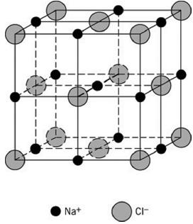
9 3. Face-centered unit cell. Four atoms of the same kind located at 0 0 0, 1/2 1/2 0, 1/2 0 1/2 and 0 1/2 1/2. F = f e 2π i (0) + f e 2π i (h/2 + k/2) + f e 2π i (h/2 + l/2) + f e2π i (k/2 + l/2) = f [1 + e π i (h + k) + e π i (h + l) + e π i (k + l) ] If h, k, and l are unmixed, then the sums (h + k), (h + l) and (k + l) are even integers and each term in the above equation has the value 1. F = 4f for unmixed indices; If h, k and l are mixed, then the sum of the three exponentials is -1, whether two of the indices are odd and one even or two even and one odd. So F = 0 for mixed indices Thus, reflections may occur for such planes as (111), (200) and (220) but not for the planes (100), (210), (112) etc. Note: Structure factor is independent of the shape and size of the unit cell. It means that rules of missing reflections apply to all kinds of unit cells of any dimension; cubic, tetragonal, orthorhombic etc. 4. The Example of NaCl: It has a cubic lattice with 4 Na and 4 Cl atoms per unit cell, located as follows: Na /2 1/2 0 1/2 0 1/2 0 1/2 1/2 Cl 1/2 1/2 1/2 1/ / /2
10 F = f Na e 2π i (0) + f Na e 2π i (h/2 + k/2) + f Na e 2π i (h/2 + l/2) + f Na e 2π i (k/2 + l/2) + f Cl e 2π i (h/2 + k/2 + l/2) + f Cl e 2π i (h/2) + f Cl e 2π i (k/2) + f Cl e2π i ( l/2) = f Na [1 + e π i (h + k) + e π i (h + l) + e π i (k + l) ] + f Cl [e π i (h + k + l) + e π ih + e π ik + e π il ] In case of NaCl, the sodium-atom positions are related by the face centering translations and so are the chlorine-atom positions. Whenever a lattice contains common translations, the corresponding terms in the structure factor equation can always be factored out, leading to considerable simplification. In this case: F = f Na [1 + e π i (h + k) + e π i (h + l) + e π i (k + l) ] + f Cl e π i (h + k + l) [1 + e π i ( k l) + e π i ( h l) + e π i ( h k) ] The signs of the exponents in the second bracket may be changed: F = f Na [1 + e π i (h + k) + e π i (h + l) + e π i (k + l) ] + f Cl e π i (h + k + l) [1 + e π i (k + l) + e π i (h + l) + e π i (h + k) ] As e nπi = e nπ i F = [1 + e π i (h + k) + e π i (h + l) + e π i (k + l) ] [ f Na + f Cl e π i (h + k + l) ] Here the terms corresponding to the face-centering translations appear in the first factor; the second term contains the terms that describe the basis of the unit cell, namely, the Na atom at and the Cl atom at ½ ½ ½. The first term have a total value of zero for mixed indices and 4 for unmixed indices as described earlier for face-cetered unit cell. This shows at once that NaCl has a face-centered lattice and that:
11 F = 0 for mixed indices For unmixed indices F 2 = 0 F = 4 [ f Na + f Cl e π i (h + k + l) ] F = 4 (f Na + f Cl ) if (h + k + l) is even; F 2 = 16 (f Na + f Cl ) 2 F = 4 (f Na f Cl ) if (h + k + l) is odd; F 2 = 16 (f Na f Cl ) 2 In this case, there are more than four atoms per unit cell (8), but the lattice is still facecentered. The introduction of additional atoms has not eliminated any reflections present in the case of the four-atom cell, but it has decreased some in intensity. 5. Example CsCl Let s calculate the structure factors for the first 6 peaks of CsCl. To do this we need to know the atomic positions and the Miller Indices.
 is odd number when (h + k + l) is even number F 110 = f Cl + f Cs F 220 = f Cl + f Cs F 221 = f Cl + f Cs")
12 F = f Cl e 2π i (0) + f Cs e2π i (h/2 + k/2 + l/2) F = f Cl e 2π i (0) + f Cs eπ i (h + k + l) F = f Cl f Cs F = f Cl + f Cs F 100 = f Cl f Cs F 111 = f Cl f Cs F 210 = f Cl f Cs when (h + k + l) is odd number when (h + k + l) is even number F 110 = f Cl + f Cs F 220 = f Cl + f Cs F 221 = f Cl + f Cs
13 Temperature Factor The atoms in a crystal undergo thermal vibration about their mean positions and the amplitude of this vibration increases as the temperature is increased. For example at room temperature the average displacement of an atom of aluminum from its mean position is 0.17 Å, which is about 6 percent of the distance of closest approach of the mean atom positions in this crystal. Thermal vibration of the atoms has three main effects: 1. The unit cell expands, causing changes in periodicity of d and therefore in the 2θ positions of the diffraction lines. 2. The intensities of the diffraction lines decrease 3. The intensity of the background scattering between lines increases. Thermal agitation decreases the intensity of diffracted beam because it degrades the periodicity of the lattice. In intensity calculations this effect is included by introducing the temperature factor e 2M, which is a number by which the calculated intensity is to be multiplied to allow for thermal vibration of the atoms. (f = f 0 e M ) The quantity M depends on both the amplitude of thermal vibration and the scattering angle 2θ. M = 8π 2 ū 2 (sinθ/ λ) 2 = B (sinθ/λ ) 2
14 Where ū is the mean square displacement of the atom in a direction normal to the diffracting plane and the coefficient B is the isotropic temperature factor and is proportional to the mean squared displacement of the atoms. More sophisticated treatments assume different values of B for each crystallographically independent atom and anisotropic vibrations (elliptical in shape rather than spherical). Isotropic factor: B or ū Anisotropic factor: B 11, B 22, B 33, B 12, B 13, B 23, ū 11, ū 22, ū 33, ū 12, ū 13, ū 23 The thermal vibration of atoms has another effect on diffraction patterns. Besides decreasing the intensity of diffraction lines, it causes some general coherent scattering in all directions. This is called temperature-diffuse scattering; it contributes only to the general background of the pattern and its intensity gradually increases with 2θ.
15 Absorption Factor According to Beer s law, absorption reduces the intensity of an X-ray beam travelling through a given material by an amount which depends on the material and the length of the path travelled by the radiation in it. The intensity of the diffracted X-rays is reduced due to absorption by the factor: I /I 0 = e µx Here x is the total path length and µ is the linear absorption coefficient of the crystal. Lorentz Factor There are a number of factors that lead to angle dependence of the peak intensities (integrated intensities). 1. Diffraction can occur for angles slightly different from the value predicted by Bragg s Law I 1/sin(2θ). 2. The number of crystals oriented in such a way as to satisfy Bragg s Law is highest for low angles I cos(θ) 3. The fraction of the diffraction cone that intersects the detector is highest at low angles I 1/sin(2θ)

16 When combine these considerations and do some trigonometric manipulation we get the Lorentz Factor: I 1/(4sin 2 θ cosθ) Polarization and the LP Factor An X-ray propagating in the x-direction will have an electric vector oriented in the yz plane. The y and z components of the X-ray will be scattered differently because the angle between the scattered beam and the electric field gradient will differ, as derived by Thompson. This leads to the polarization factor: I (1+cos 2 2θ)/2 Typically the Lorentz and Polarization terms are combined to give the Lorentz- Polarization (LP) factor. I (1+cos 2 2θ)/(8sin 2 θ cosθ)
17 The overall effect of these geometrical factors is to decrease the intensity of the reflections at intermediate angle compared to those in forward or backward directions.

18 Extinctions Intensity calculation formula is derived for ideally imperfect crystal, one consisting of quite small mosaic blocks which are randomly oriented. Such a crystal has maximum diffracting power. A crystal made up of large mosaic blocks is more nearly perfect and has a lower diffracting power. This decrease in the integrated intensity of the diffracted beam as the crystal becomes more nearly perfect is called extinction. Destructive interference from re-reflections within the crystals. The strong peaks appear weaker. The solution is to grind the powdered sample more.
19 Examples of Intensity Calculation 1. Peak Positions and Intensity Calculations for copper Copper is an face-centered cubic with cell parameter a = Å. Diffraction pattern is measured with Cu Kα radiation Line hkl h 2 +k 2 +l 2 sin 2 θ sinθ θ sinθ /λ f cu
20 Line F 2 M LP Cal. Intensity Relative Intensity (%) Obs. Intensity vs s s s m w s s
21 2. Peak Positions and Intensity Calculations ZnS ZnS (zinc blende) is cubic and has a lattice parameter of 5.41 Å. The first step is to calculate the structure factor. ZnS has four zinc and four sulfur atoms per unit cell, located at the following positions. Zn: ¼ ¼ ¼ + face-centering translations S: face-centering translations Since structure is face-centered, the structure factor will be zero for planes of mixed indices. From example of NaCl, the terms in the structure factor equation corresponding to the face-centering translations can be factored out and the equation for unmixed indices written down at once: F = 4[f s + f Zn e (πi/2)(h + k + l) ] F 2 is obtained by multiplication of the above by its complex conjugate: F 2 = 16[f s + f Zn e (πi/2)(h + k + l) ] [f s + f Zn e (πi/2)(h + k + l) ] This reduces to the following form: F 2 = 16[f 2 s + f 2 Zn +2f s f Zn cos(x/2)(h + k + l)] Further simplification is possible for various special cases:
22 F 2 = 16[f 2 s + f 2 Zn ] when (h + k + l) is odd F 2 = 16[f s f Zn ] 2 when (h + k + l) is an odd multiple of 2 F 2 = 16[f s + f Zn ] 2 when (h + k + l) is an even multiple of 2 The intensity calculations are carried out in the table below: Line hkl θ sinθ /λ f S f Zn
23 Line F 2 M LP Relative Intensity (%) (Calc.) Obs. Intensity vs w vs vs vw w
24 Determination of Atom Positions The observed relative intensities are determined by the atom positions in the unit cell. However, there is no known procedure of directly calculating atom positions from observed intensities. Atom positions are rather calculated by trial and error method. A set of atom positions is assumed, the intensities corresponding to these positions are calculated and the calculated intensities are compared with the observed ones, the process being repeated until satisfactory agreement is reached. This trial method is further aided by the accumulated knowledge of previously known structures. From these known structures a few likely candidates may be selected as a starting point. There are many complex structures which can not be solved by this simple approach. Two powerful methods of space group theory and Fourier series are used in these cases. For example if a given substance is known to be tetragonal and to have n atoms in its unit cell, then space-group theory lists all possible arrangements of n atoms which will have tetragonal symmetry. This listing of possible arrangements is further aided by the knowledge of systematic absences.
25 A Fourier series is a type of infinite trigonometric series by which any kind of periodic function may be expressed. Now the one essential property of a crystal is that its atoms are arranged in space in a periodic fashion. This means that density of electrons is also a periodic function of position in the crystal, rising to maximum at the point where an atom is located and dropping to a low value in the region between atoms. Since the electron density is a periodic function of position of atoms, a crystal may be described analytically by means of the Fourier series. Example of Structure Determination Consider an intermediate phase which occurs in the cadmium-tellurium system. Chemical analysis of the specimen showed that it contains 46.6 weight percent Cd and 53.4 weight percent Te. This is equivalent to 49.8 atomic percent Cd and can be represented by the formula CdTe. Powder X-ray diffraction pattern was collected by using Cu K α radiation. The observed values of sin 2 θ for the first 16 lines are listed in the Table 1, together with the visually estimated relative line intensities. This pattern can be indexed on the basis of a cubic unit cell and the indices of the observed lines are given in the Table 1. The lattice parameter, calculated from the sin 2 θ value for the highest line, is 6.46 Å. The density of the specimen, as determined by weighing a quantity of the powder in a pyknometer bottle was 5.82 g/cm 3.
26 The sum of atomic weights can be calculated as: A = 3 (5.82)(6.46) = 945 Since the molecular weight of CdTe is , the number of molecules per unit cell is 945/ = 3.94, or 4 within experimental error. Knowing the unit cell of CdTe is cubic and that it contains 4 molecules of CdTe, i.e., 4 atoms of Cd and 4 atoms of Te, possible arrangement of these atoms in the unit cell can be evaluated. Examination of the indices listed in Table 1 reveals that the indices of the observed lines are all unmixed and that the Bravais lattice must be face-centered. Not all possible of sets of unmixed indices are present, however: 200, 420, 600, 442, 622 and 640 are missing from the pattern. These reflections may be too weak to be observed. Now there are two common face-centered cubic structures of AB type i.e., containing two different atoms in equal proportions and both contain four molecules per unit cell: these are the NaCl structure and the zinc-blende form of ZnS. Both these are logical possibilities. The next step is to calculate relative diffracted intensities for each structure and compare them with experiment, in order to determine whether or not one of these structures is correct one. If CdTe has the NaCl structure, then its structure factor for unmixed indices is given by:
27 F = 4 (f Cd + f Te ) if (h + k + l) is even; F 2 = 16 (f Cd + f Te ) 2 F = 4 (f Cd f Te ) if (h + k + l) is odd; F 2 = 16 (f Cd f Te ) 2 On the other hand, if the ZnS structure is correct, then the structure factor for unmixed indices is given by: F 2 = 16[f 2 Cd + f 2 Te ] when (h + k + l) is odd F 2 = 16[f Cd f Te ] 2 when (h + k + l) is an odd multiple of 2 F 2 = 16[f Cd + f Te ] 2 when (h + k + l) is an even multiple of 2 Even before making a detailed calculation of relative diffracted intensities, the NaCl structure can almost be eliminated as a possibility simply by inspection of above equations. The atomic numbers of Cd and Te are 48 and 52 respectively, so the value of [f Cd + f Te ] 2 is several hundred times greater than the value of [f Cd f Te ] 2 for all values of (sinθ )/λ. Then, if CdTe has the NaCl structure, the 111 reflection should be very weak and the 200 reflection very strong. Actually, 111 is strong and 200 is not observed.
28 On the other hand, if the ZnS structure is assumed, intensity calculations lead to the values listed in the fifth column. The agreement between these values and the observed intensities is excellent, except for a few minor inconsistencies among the low-angle reflections and these are due to neglect of the absorption factor. In particular, note that the ZnS structure satisfactorily accounts for all the missing reflections (200, 420, etc), since the calculated intensities of these reflections are all extremely low. Therefore this example of CdTe has the structure of the zinc-blende form of ZnS. After a given structure has been shown to be in accord with the diffraction data, it is advisable to calculate the interatomic distances involved in that structure. This calculation not only is of interest in itself but also to disclose any gross errors that may have been made, since there is obviously something wrong with the proposed structure if it brings certain atoms impossibly close together. In the present structure, the nearest neighbour to the Cd atom at is the Te atom at ¼ ¼ ¼. The Cd-Te interatomic distance is therefore a/4 = 2.80 Å which is quite reasonable.
29 Table 1 Line Intensity sin 2 θ hkl 1 s vs vs vw m m s m , w m m w w m , vs s , 553
30 Table 2 Line hkl Obs. Intensity Cal. I (NaCl) Cal. I (ZnS) s nil vs vs vw m m nil s , 233 m w m , 442 nil m w nil w , 551 m nil vs , 553 s 3.3 *Calculated intensities have been adjusted so that the 220 line has an intensity of 10.0 for both structures.
31 Residual Stress and Strain Strain in a material can produce two types of diffraction effects. If the strain is uniform (either tensile or compressive) it is called macrostrain and the unit cell distances will become either larger or smaller resulting in a shift in the diffraction peaks in the pattern. Macrostrain causes the lattice parameters to change in a permanent (but possibly reversible) manner resulting in a peak shift. Macrostrains may be induced by heating of clay minerals. Microstrains are produced by a distribution of tensile and compressive forces resulting in a broadening of the diffraction peaks. In some cases, some peak asymmetry may be the result of microstrain. Microstress in crystallites may come from dislocations, vacancies, shear planes, etc; the effect will generally be a distribution of peaks around the unstressed peak location, and a crude broadening of the peak in the resultant pattern.
32 Crystallite Size For large crystallites (i.e., thousands of unit cells), diffraction will result in sharp diffraction peaks only at the precise location of the Bragg angle. If the particle size is smaller (such that there are insufficient lattice planes to effectively cancel all incoherent scattering at angles close to the Bragg angle) the net result will be a broadening of the diffraction peak around the Bragg angle. This phenomenon of widening of diffraction peaks is related to incomplete canceling of small deviations from the Bragg angle in small crystallites is known as particle size broadening. Particle size broadening is differentiated from the normal width of diffraction peaks related to instrumental effects. In most cases, particle size broadening will not be observed with crystallite sizes larger than 1 µm. The crystallite size broadening (β τ ) of a peak can usually be related to the mean crystallite dimension (τ) by the Scherrer equation: where β τ is the line broadening due to the effect of small crystallites and is given by (B b), B being the breadth of the observed diffraction line at its half-intensity maximum, and b the instrumental broadening or breadth of a peak that exhibits no broadening beyond the inherent instrumental peak width.
33 Note that β τ is given in radians, and that K is the shape factor which typically has a value of about 0.9. As shown below, particle size broadening is not significant at sizes above 10,000 Å (1 µm). When instrumental parameters are known (i.e., FWHM values for crystallites larger than 1 µm), the relationship above may be used to calculate crystallite sizes as small as 10 Å if the structures are unstrained. It is interesting to think of particle size broadening when considering the diffraction pattern obtained from many amorphous materials. Typically these materials (like glass and plastics) will give an extremely broad peak over an angular range of perhaps 2θ 5 10 that will look like a hump in the background. One can think of this hump as an extreme example of particle size broadening where the short range ordering is on the order of a several angstroms.
34 Lanthanum hexaboride (LaB 6 ) has the narrowest peaks of any material and for all practical purposes one can consider all measured peak broadening as being due to instrumental factors. Resolving Power of Diffractometer The sensitivity of change of the 2 θ angle for a reflection with change in d hkl -spacing is the measure of the resolving power of the diffraction technique. The resolving power or the limit of resolution, δd / d, can be obtained by differentiating Bragg s law with respect to d and θ (λ fixed), i.e. λ = 2d sinθ differentiating 0 = 2d cosθ δθ +2sinθ δd hence δd/d = cotθ δθ For a given value of 2δθ, which may be expressed in terms of the minimum resolved distance between two reflections, and for the smallest limit of resolution we want cotθ values to be as small as possible, or for a given value of δd/d, we want the angular separation of the reflections 2δθ to be large, and hence again cotθ values to be as small as possible. As we know that cotθ values are high at low angles and rapidly decrease towards zero as θ approaches 90º. Hence d hkl -spacing measurements are most accurate using high angle reflections.
X-ray Diffraction. Diffraction. X-ray Generation. X-ray Generation. X-ray Generation. X-ray Spectrum from Tube
 X-ray Diffraction Mineral identification Mode analysis Structure Studies X-ray Generation X-ray tube (sealed) Pure metal target (Cu) Electrons remover inner-shell electrons from target. Other electrons
Basic Crystallography Part 1. Theory and Practice of X-ray Crystal Structure Determination
 Basic Crystallography Part 1 Theory and Practice of X-ray Crystal Structure Determination We have a crystal How do we get there? we want a structure! The Unit Cell Concept Ralph Krätzner Unit Cell Description
X-ray, Neutron and e-beam scattering
 X-ray, Neutron and e-beam scattering Introduction Why scattering? Diffraction basics Neutrons and x-rays Techniques Direct and reciprocal space Single crystals Powders CaFe 2 As 2 an example What is the
SOLID STATE 9. Determination of Crystal Structures
 SOLID STATE 9 Determination of Crystal Structures In the diffraction experiment, we measure intensities as a function of d hkl. Intensities are the sum of the x-rays scattered by all the atoms in a crystal.
X-ray Diffraction. Interaction of Waves Reciprocal Lattice and Diffraction X-ray Scattering by Atoms The Integrated Intensity
 X-ray Diraction Interaction o Waves Reciprocal Lattice and Diraction X-ray Scattering by Atoms The Integrated Intensity Basic Principles o Interaction o Waves Periodic waves characteristic: Frequency :
Resolution: maximum limit of diffraction (asymmetric)
") Resolution: maximum limit of diffraction (asymmetric) crystal Y X-ray source 2θ X direct beam tan 2θ = Y X d = resolution 2d sinθ = λ detector 1 Unit Cell: two vectors in plane of image c* Observe: b*
Resolution: maximum limit of diffraction (asymmetric) crystal Y X-ray source 2θ X direct beam tan 2θ = Y X d = resolution 2d sinθ = λ detector 1 Unit Cell: two vectors in plane of image c* Observe: b*
Physical Chemistry I. Crystal Structure
 Physical Chemistry I Crystal Structure Crystal Structure Introduction Crystal Lattice Bravis Lattices Crytal Planes, Miller indices Distances between planes Diffraction patters Bragg s law X-ray radiation
The structure of liquids and glasses. The lattice and unit cell in 1D. The structure of crystalline materials. Describing condensed phase structures
 Describing condensed phase structures Describing the structure of an isolated small molecule is easy to do Just specify the bond distances and angles How do we describe the structure of a condensed phase?
Rajesh Prasad Department of Applied Mechanics Indian Institute of Technology New Delhi
 TEQIP WORKSHOP ON HIGH RESOLUTION X-RAY AND ELECTRON DIFFRACTION, FEB 01, 2016, IIT-K. Introduction to x-ray diffraction Peak Positions and Intensities Rajesh Prasad Department of Applied Mechanics Indian
Introduction to crystallography The unitcell The resiprocal space and unitcell Braggs law Structure factor F hkl and atomic scattering factor f zθ
 Introduction to crystallography The unitcell The resiprocal space and unitcell Braggs law Structure factor F hkl and atomic scattering factor f zθ Introduction to crystallography We divide materials into
Data processing and reduction
 Data processing and reduction Leopoldo Suescun International School on Fundamental Crystallography 2014 May 1st, 2014 Reciprocal lattice c* b* b * dh' k' l' 1 dh' k' l' * dhkl 1 dhkl a a* 0 d hkl c bc
An Introduction to Diffraction and Scattering. School of Chemistry The University of Sydney
 An Introduction to Diffraction and Scattering Brendan J. Kennedy School of Chemistry The University of Sydney 1) Strong forces 2) Weak forces Types of Forces 3) Electromagnetic forces 4) Gravity Types
3.012 Structure An Introduction to X-ray Diffraction
 3.012 Structure An Introduction to X-ray Diffraction This handout summarizes some topics that are important for understanding x-ray diffraction. The following references provide a thorough explanation
Keble College - Hilary 2012 Section VI: Condensed matter physics Tutorial 2 - Lattices and scattering
 Tomi Johnson Keble College - Hilary 2012 Section VI: Condensed matter physics Tutorial 2 - Lattices and scattering Please leave your work in the Clarendon laboratory s J pigeon hole by 5pm on Monday of
with any accuracy. The parameter a of cubic substances is directly proportional to the spacing d of any particular set of lattice planes:
 The change in solute concentration or temperature produce only a small change in lattice parameter precise parameter measurements is needed to measure these quantities with any accuracy. The parameter
Handout 7 Reciprocal Space
 Handout 7 Reciprocal Space Useful concepts for the analysis of diffraction data http://homepages.utoledo.edu/clind/ Concepts versus reality Reflection from lattice planes is just a concept that helps us
Roger Johnson Structure and Dynamics: X-ray Diffraction Lecture 6
 6.1. Summary In this Lecture we cover the theory of x-ray diffraction, which gives direct information about the atomic structure of crystals. In these experiments, the wavelength of the incident beam must
Saveetha Engineering College, Thandalam, Chennai. Department of Physics. First Semester. Ph6151 Engineering Physics I (NOV/DEC 2014)
") Saveetha Engineering College, Thandalam, Chennai. Department of Physics First Semester Ph6151 Engineering Physics I (NOV/DEC 2014) Part A (Questions and Answers) 1. Distinguish between Crystalline and
Saveetha Engineering College, Thandalam, Chennai. Department of Physics First Semester Ph6151 Engineering Physics I (NOV/DEC 2014) Part A (Questions and Answers) 1. Distinguish between Crystalline and
General theory of diffraction
 General theory of diffraction X-rays scatter off the charge density (r), neutrons scatter off the spin density. Coherent scattering (diffraction) creates the Fourier transform of (r) from real to reciprocal
UNIT I SOLID STATE PHYSICS
 UNIT I SOLID STATE PHYSICS CHAPTER 1 CRYSTAL STRUCTURE 1.1 INTRODUCTION When two atoms are brought together, two kinds of forces: attraction and repulsion come into play. The force of attraction increases
X-ray analysis. 1. Basic crystallography 2. Basic diffraction physics 3. Experimental methods
 X-ray analysis 1. Basic crystallography 2. Basic diffraction physics 3. Experimental methods Introduction Noble prizes associated with X-ray diffraction 1901 W. C. Roentgen (Physics) for the discovery
FROM DIFFRACTION TO STRUCTURE
 3.012 Fund of Mat Sci: Structure Lecture 19 FROM DIFFRACTION TO STRUCTURE Images removed for copyright reasons. 3-fold symmetry in silicon along the [111] direction. Forward (left) and backward (right)
SOLID STATE 18. Reciprocal Space
 SOLID STATE 8 Reciprocal Space Wave vectors and the concept of K-space can simplify the explanation of several properties of the solid state. They will be introduced to provide more information on diffraction
Experiment 3: Simulating X-Ray Diffraction CH3500: Inorganic Chemistry, Plymouth State University
 Experiment 3: Simulating X-Ray Diffraction CH3500: Inorganic Chemistry, Plymouth State University Created by Jeremiah Duncan, Dept. of Atmospheric Science and Chemistry, Plymouth State University (2012).
The Reciprocal Lattice
 59-553 The Reciprocal Lattice 61 Because of the reciprocal nature of d spacings and θ from Bragg s Law, the pattern of the diffraction we observe can be related to the crystal lattice by a mathematical
1 Crystal Structures. of three-dimensional crystals. Here we use two-dimensional examples to illustrate the concepts.
 3 1 Crystal Structures A crystal is a periodic array of atoms. Many elements and quite a few compounds are crystalline at low enough temperatures, and many of the solid materials in our everyday life (like
Setting The motor that rotates the sample about an axis normal to the diffraction plane is called (or ).
.") X-Ray Diffraction X-ray diffraction geometry A simple X-ray diffraction (XRD) experiment might be set up as shown below. We need a parallel X-ray source, which is usually an X-ray tube in a fixed position
X-Ray Diffraction X-ray diffraction geometry A simple X-ray diffraction (XRD) experiment might be set up as shown below. We need a parallel X-ray source, which is usually an X-ray tube in a fixed position
Basics of XRD part III
 Basics of XRD part III Dr. Peter G. Weidler Institute of Functional Interfaces IFG 1 10/31/17 KIT The Research University of the Helmholtz Association Name of Institute, Faculty, Department www.kit.edu
Analytical Methods for Materials
 Analytical Methods for Materials Laboratory Module # Crystal Structure Determination for Non-Cubic Crystals Suggested Reading 1. Y. Waseda, E. Matsubara, and K. Shinoda, X-ray Diffraction Crystallography,
Suggested Reading. Pages in Engler and Randle
 The Structure Factor Suggested Reading Pages 303-312312 in DeGraef & McHenry Pages 59-61 in Engler and Randle 1 Structure Factor (F ) N i1 1 2 i( hu kv lw ) F fe i i j i Describes how atomic arrangement
Crystal planes. Neutrons: magnetic moment - interacts with magnetic materials or nuclei of non-magnetic materials. (in Å)
") Crystallography: neutron, electron, and X-ray scattering from periodic lattice, scattering of waves by periodic structures, Miller indices, reciprocal space, Ewald construction. Diffraction: Specular,
Crystallography: neutron, electron, and X-ray scattering from periodic lattice, scattering of waves by periodic structures, Miller indices, reciprocal space, Ewald construction. Diffraction: Specular,
Chapter 2. X-ray X. Diffraction and Reciprocal Lattice. Scattering from Lattices
 Chapter. X-ray X Diffraction and Reciprocal Lattice Diffraction of waves by crystals Reciprocal Lattice Diffraction of X-rays Powder diffraction Single crystal X-ray diffraction Scattering from Lattices
High-Resolution. Transmission. Electron Microscopy
 Part 4 High-Resolution Transmission Electron Microscopy 186 Significance high-resolution transmission electron microscopy (HRTEM): resolve object details smaller than 1nm (10 9 m) image the interior of
Solids. properties & structure
 Solids properties & structure Determining Crystal Structure crystalline solids have a very regular geometric arrangement of their particles the arrangement of the particles and distances between them is
Structure of Crystalline Solids
 Structure of Crystalline Solids Solids- Effect of IMF s on Phase Kinetic energy overcome by intermolecular forces C 60 molecule llotropes of Carbon Network-Covalent solid Molecular solid Does not flow
PART 1 Introduction to Theory of Solids
 Elsevier UK Job code: MIOC Ch01-I044647 9-3-2007 3:03p.m. Page:1 Trim:165 240MM TS: Integra, India PART 1 Introduction to Theory of Solids Elsevier UK Job code: MIOC Ch01-I044647 9-3-2007 3:03p.m. Page:2
Geometry of Crystal Lattice
 0 Geometry of Crystal Lattice 0.1 Translational Symmetry The crystalline state of substances is different from other states (gaseous, liquid, amorphous) in that the atoms are in an ordered and symmetrical
Scattering Lecture. February 24, 2014
 Scattering Lecture February 24, 2014 Structure Determination by Scattering Waves of radiation scattered by different objects interfere to give rise to an observable pattern! The wavelength needs to close
Phys 460 Describing and Classifying Crystal Lattices
 Phys 460 Describing and Classifying Crystal Lattices What is a material? ^ crystalline Regular lattice of atoms Each atom has a positively charged nucleus surrounded by negative electrons Electrons are
Introduction to X-ray and neutron scattering
 UNESCO/IUPAC Postgraduate Course in Polymer Science Lecture: Introduction to X-ray and neutron scattering Zhigunov Alexander Institute of Macromolecular Chemistry ASCR, Heyrovsky sq., Prague -16 06 http://www.imc.cas.cz/unesco/index.html
Crystallography Reading: Warren, Chapters 2.1, 2.2, 2.6, 8 Surface symmetry: Can be a clue to underlying structure. Examples:
 Crystallography Reading: Warren, Chapters 2.1, 2.2, 2.6, 8 Surface symmetry: Can be a clue to underlying structure. Examples: Snow (SnowCrystals.com) Bismuth (Bao, Kavanagh, APL 98 66103 (2005) Hexagonal,
Scattering and Diffraction
 Scattering and Diffraction Andreas Kreyssig, Alan Goldman, Rob McQueeney Ames Laboratory Iowa State University All rights reserved, 2018. Atomic scale structure - crystals Crystalline materials... atoms
LAB 01 X-RAY EMISSION & ABSORPTION
 LAB 0 X-RAY EMISSION & ABSORPTION REPORT BY: TEAM MEMBER NAME: Ashley Tsai LAB SECTION No. 05 GROUP 2 EXPERIMENT DATE: Feb., 204 SUBMISSION DATE: Feb. 8, 204 Page of 3 ABSTRACT The goal of this experiment
Crystallographic Symmetry. Jeremy Karl Cockcroft
 Crystallographic Symmetry Jeremy Karl Cockcroft Why bother? To describe crystal structures Simplifies the description, e.g. NaCl structure Requires coordinates for just 2 atoms + space group symmetry!
Data Collection. Overview. Methods. Counter Methods. Crystal Quality with -Scans
 Data Collection Overview with a unit cell, possible space group and computer reference frame (orientation matrix); the location of diffracted x-rays can be calculated (h k l) and intercepted by something
Solids / Crystal Structure
 The first crystal analysis proved that in the typical inorganic salt, NaCl, there is no molecular grouping. The inference that the structure consists of alternate ions of sodium and chlorine was an obvious
Structure Report for J. Reibenspies
 X-ray Diffraction Laboratory Center for Chemical Characterization and Analysis Department of Chemistry Texas A & M University Structure Report for J. Reibenspies Project Name: Sucrose Date: January 29,
Axial Ratios, Parameters, Miller Indices
 Page 1 of 7 EENS 2110 Tulane University Mineralogy Prof. Stephen A. Nelson Axial Ratios, Parameters, Miller Indices This document last updated on 07-Sep-2016 We've now seen how crystallographic axes can
Experimental Determination of Crystal Structure
 Experimental Determination of Crystal Structure Branislav K. Nikolić Department of Physics and Astronomy, University of Delaware, U.S.A. PHYS 624: Introduction to Solid State Physics http://www.physics.udel.edu/~bnikolic/teaching/phys624/phys624.html
Homework 1 (not graded) X-ray Diffractometry CHE Multiple Choice. 1. One of the methods of reducing exposure to radiation is to minimize.
 X-ray Diffractometry CHE Multiple Choice. 1. One of the methods of reducing exposure to radiation is to minimize.") Homework 1 (not graded) X-ray Diffractometry CHE 380.45 Multiple Choice 1. One of the methods of reducing exposure to radiation is to minimize. a) distance b) humidity c) time d) speed e) shielding 2.
Homework 1 (not graded) X-ray Diffractometry CHE 380.45 Multiple Choice 1. One of the methods of reducing exposure to radiation is to minimize. a) distance b) humidity c) time d) speed e) shielding 2.
TEP Examination of the structure of NaCl monocrystals with different orientations
 Examination of the structure of NaCl TEP Related topics Characteristic X-radiation, energy levels, crystal structures, reciprocal lattices, Miller indices, atomic form factor, structure factor, and Bragg
Nove fizickohemijske metode. Ivana Radosavljevic Evans Durham University, UK
 Nove fizickohemijske metode Ivana Radosavljevic Evans Durham University, UK Nove fizickohemijske metode: Metode zasnovane na sinhrotronskom zracenju Plan predavanja: Difrakcione metode strukturne karakterizacije
Symmetry. 2-D Symmetry. 2-D Symmetry. Symmetry. EESC 2100: Mineralogy 1. Symmetry Elements 1. Rotation. Symmetry Elements 1. Rotation.
 Symmetry a. Two-fold rotation = 30 o /2 rotation a. Two-fold rotation = 30 o /2 rotation Operation Motif = the symbol for a two-fold rotation EESC 2100: Mineralogy 1 a. Two-fold rotation = 30 o /2 rotation
Structural Characterization of Nanoparticles
 Structural Characterization of Nanoparticles Nicola Pinna Max Planck Institute of Colloids and Interfaces e-mail: pinna@mpikg-golm.mpg.de - http://www.pinna.cx Plan 1. Transmission Electron Microscopy
Chem 728 Introduction to Solid Surfaces
 Chem 728 Introduction to Solid Surfaces Solids: hard; fracture; not compressible; molecules close to each other Liquids: molecules mobile, but quite close to each other Gases: molecules very mobile; compressible
The Solid State. Phase diagrams Crystals and symmetry Unit cells and packing Types of solid
 The Solid State Phase diagrams Crystals and symmetry Unit cells and packing Types of solid Learning objectives Apply phase diagrams to prediction of phase behaviour Describe distinguishing features of
Condensed Matter Physics Prof. G. Rangarajan Department of Physics Indian Institute of Technology, Madras
 (Refer Slide Time: 00:11) Condensed Matter Physics Prof. G. Rangarajan Department of Physics Indian Institute of Technology, Madras Diffraction Methods for Crystal Structure Worked Examples Next, we have
XRD Intensity Calculations -Example FCC Cu (centric)
") Ihkl F hkl F hkl hkl f f Cu Cu ( e (1 e XRD Intensity Calculations -Example FCC Cu (centric) Consider Copper which is F 3 with a=3.615å; atoms in positions [0,0,0] m m [½,½,0][½,0,½][0,½,½] and l=1.54å
Ihkl F hkl F hkl hkl f f Cu Cu ( e (1 e XRD Intensity Calculations -Example FCC Cu (centric) Consider Copper which is F 3 with a=3.615å; atoms in positions [0,0,0] m m [½,½,0][½,0,½][0,½,½] and l=1.54å
Chapter 2 Kinematical theory of diffraction
 Graduate School of Engineering, Nagoya Institute of Technology Crystal Structure Analysis Taashi Ida (Advanced Ceramics Research Center) Updated Oct. 29, 2013 Chapter 2 Kinematical theory of diffraction
Structure and Dynamics : An Atomic View of Materials
 Structure and Dynamics : An Atomic View of Materials MARTIN T. DOVE Department ofearth Sciences University of Cambridge OXFORD UNIVERSITY PRESS Contents 1 Introduction 1 1.1 Observations 1 1.1.1 Microscopic
Crystal Structure. Dr Bindu Krishnan
 Solid State Physics-1 Crystal Structure Dr Bindu Krishnan CRYSTAL LATTICE What is crystal (space) lattice? In crystallography, only the geometrical properties of the crystal are of interest, therefore
Rietveld method - grounds
 07 July 2010 Rietveld method - grounds Miguel Ángel García Aranda Departamento de Química Inorgánica Universidad de Málaga g_aranda@uma.es http://webpersonal.uma.es/~mag-aranda/ Outline 1.- (Very brief)
What use is Reciprocal Space? An Introduction
 What use is Reciprocal Space? An Introduction a* b* x You are here John Bargar 5th Annual SSRL Workshop on Synchrotron X-ray Scattering Techniques in Materials and Environmental Sciences June 1-3, 2010
Atomic Arrangement. Primer Materials For Science Teaching Spring
 Atomic Arrangement Primer Materials For Science Teaching Spring 2016 31.3.2015 Levels of atomic arrangements No order In gases, for example the atoms have no order, they are randomly distributed filling
Understanding Single-Crystal X-Ray Crystallography Exercises and Solutions
 Understanding Single-Crystal X-Ray Crystallography Exercises and Solutions Dennis W. Bennett Department of Chemistry and Biochemistry University of Wisconsin-Milwaukee Chapter Crystal Lattices. The copper
Röntgenpraktikum. M. Oehzelt. (based on the diploma thesis of T. Haber [1])
![Röntgenpraktikum. M. Oehzelt. (based on the diploma thesis of T. Haber [1])](/thumbs/91/106501237.jpg "Röntgenpraktikum. M. Oehzelt. (based on the diploma thesis of T. Haber [1])") Röntgenpraktikum M. Oehzelt (based on the diploma thesis of T. Haber [1]) October 21, 2004 Contents 1 Fundamentals 2 1.1 X-Ray Radiation......................... 2 1.1.1 Bremsstrahlung......................
Röntgenpraktikum M. Oehzelt (based on the diploma thesis of T. Haber [1]) October 21, 2004 Contents 1 Fundamentals 2 1.1 X-Ray Radiation......................... 2 1.1.1 Bremsstrahlung......................
Crystals, X-rays and Proteins
 Crystals, X-rays and Proteins Comprehensive Protein Crystallography Dennis Sherwood MA (Hons), MPhil, PhD Jon Cooper BA (Hons), PhD OXFORD UNIVERSITY PRESS Contents List of symbols xiv PART I FUNDAMENTALS
APEX CARE INSTITUTE FOR PG - TRB, SLET AND NET IN PHYSICS
 Page 1 1. Within the nucleus, the charge distribution A) Is constant, but falls to zero sharply at the nuclear radius B) Increases linearly from the centre, but falls off exponentially at the surface C)
Quiz 1 XRD ) Explain the error in the following statement: "a laser beam is a focused beam of monochromatic light".
 Explain the error in the following statement: a laser beam is a focused beam of monochromatic light.") Quiz 1 XRD 092706 Diffraction involves constructive interference between waves that emanate from structurally organized matter such as from atoms in a crystal. X-ray diffraction uses a relationship of
Quiz 1 XRD 092706 Diffraction involves constructive interference between waves that emanate from structurally organized matter such as from atoms in a crystal. X-ray diffraction uses a relationship of
print first name print last name print student id grade
 print first name print last name print student id grade Experiment 2 X-ray fluorescence X-ray fluorescence (XRF) and X-ray diffraction (XRD) may be used to determine the constituent elements and the crystalline
DIFFRACTION PHYSICS THIRD REVISED EDITION JOHN M. COWLEY. Regents' Professor enzeritus Arizona State University
 DIFFRACTION PHYSICS THIRD REVISED EDITION JOHN M. COWLEY Regents' Professor enzeritus Arizona State University 1995 ELSEVIER Amsterdam Lausanne New York Oxford Shannon Tokyo CONTENTS Preface to the first
Atomic Arrangement. Primer in Materials Spring
 Atomic Arrangement Primer in Materials Spring 2017 30.4.2017 1 Levels of atomic arrangements No order In gases, for example the atoms have no order, they are randomly distributed filling the volume to
Diamond. There are four types of solid: -Hard Structure - Tetrahedral atomic arrangement. What hybrid state do you think the carbon has?
 Bonding in Solids Bonding in Solids There are four types of solid: 1. Molecular (formed from molecules) - usually soft with low melting points and poor conductivity. 2. Covalent network - very hard with
Introduction to. Crystallography
 M. MORALES Introuction to Crystallography magali.morales@ensicaen.fr Classification of the matter in 3 states : Crystallise soli liqui or amorphous gaz soli Crystallise soli : unique arrangement of atoms
There are four types of solid:
 Bonding in Solids There are four types of solid: 1. Molecular (formed from molecules) - usually soft with low melting points and poor conductivity. 2. Covalent network - very hard with very high melting
(Re-write, January 2011, from notes of S. C. Fain Jr., L. Sorensen, O. E. Vilches, J. Stoltenberg and D. B. Pengra, Version 1, preliminary)
") Electron Diffraction (Re-write, January 011, from notes of S. C. Fain Jr., L. Sorensen, O. E. Vilches, J. Stoltenberg and D. B. Pengra, Version 1, preliminary) References: Any introductory physics text
Electron Diffraction (Re-write, January 011, from notes of S. C. Fain Jr., L. Sorensen, O. E. Vilches, J. Stoltenberg and D. B. Pengra, Version 1, preliminary) References: Any introductory physics text
Basic Crystallography Part 1. Theory and Practice of X-ray Crystal Structure Determination
 Basic Crystallography Part 1 Theory and Practice of X-ray Crystal Structure Determination Course Overview Basic Crystallography Part 1 n Introduction: Crystals and Crystallography n Crystal Lattices and
IMPROVING THE ACCURACY OF RIETVELD-DERIVED LATTICE PARAMETERS BY AN ORDER OF MAGNITUDE
 Copyright (c)jcpds-international Centre for Diffraction Data 2002, Advances in X-ray Analysis, Volume 45. 158 IMPROVING THE ACCURACY OF RIETVELD-DERIVED LATTICE PARAMETERS BY AN ORDER OF MAGNITUDE B. H.
Solid State Physics 460- Lecture 5 Diffraction and the Reciprocal Lattice Continued (Kittel Ch. 2)
") Solid State Physics 460- Lecture 5 Diffraction and the Reciprocal Lattice Continued (Kittel Ch. 2) Ewald Construction 2θ k out k in G Physics 460 F 2006 Lect 5 1 Recall from previous lectures Definition
Solid State Physics 460- Lecture 5 Diffraction and the Reciprocal Lattice Continued (Kittel Ch. 2) Ewald Construction 2θ k out k in G Physics 460 F 2006 Lect 5 1 Recall from previous lectures Definition
S.No. Crystalline Solids Amorphous solids 1 Regular internal arrangement of irregular internal arrangement of particles
 Classification of solids: Crystalline and Amorphous solids: S.No. Crystalline Solids Amorphous solids 1 Regular internal arrangement of irregular internal arrangement of particles particles 2 Sharp melting
AP5301/ Name the major parts of an optical microscope and state their functions.
 Review Problems on Optical Microscopy AP5301/8301-2015 1. Name the major parts of an optical microscope and state their functions. 2. Compare the focal lengths of two glass converging lenses, one with
X-Ray Emission and Absorption
 X-Ray Emission and Absorption Author: Mike Nill Alex Bryant February 6, 20 Abstract X-rays were produced by two bench-top diffractometers using a copper target. Various nickel filters were placed in front
THE USE OF PEARSON VII DISTRIBUTION FUNCTIONS IN X-RA Y DIFFR ACTION RESIDUAL STRESS MEASUREMENT
 THE USE OF PEARSON VII DISTRIBUTION FUNCTIONS IN X-RA Y DIFFR ACTION RESIDUAL STRESS MEASUREMENT Paul S. Prevéy Lambda Research ABSTRACT The fitting of a parabola by least squares regression to the upper
Phys 412 Solid State Physics. Lecturer: Réka Albert
 Phys 412 Solid State Physics Lecturer: Réka Albert What is a solid? A material that keeps its shape Can be deformed by stress Returns to original shape if it is not strained too much Solid structure
Inorganic Chemistry I (CH331) Solid-state Chemistry I (Crystal structure) Nattapol Laorodphan (Chulabhorn Building, 4 th Floor)
 Solid-state Chemistry I (Crystal structure) Nattapol Laorodphan (Chulabhorn Building, 4 th Floor)") Inorganic Chemistry I (CH331) Solid-state Chemistry I (Crystal structure) Nattapol Laorodphan (Chulabhorn Building, 4 th Floor) 7/2013 N.Laorodphan 1 Text books : 1. D.F. Sheiver, P.W. Atkins & C.H. Langford
Inorganic Chemistry I (CH331) Solid-state Chemistry I (Crystal structure) Nattapol Laorodphan (Chulabhorn Building, 4 th Floor) 7/2013 N.Laorodphan 1 Text books : 1. D.F. Sheiver, P.W. Atkins & C.H. Langford
disordered, ordered and coherent with the substrate, and ordered but incoherent with the substrate.
 5. Nomenclature of overlayer structures Thus far, we have been discussing an ideal surface, which is in effect the structure of the topmost substrate layer. The surface (selvedge) layers of the solid however
Solid State Physics Lecture 3 Diffraction and the Reciprocal Lattice (Kittel Ch. 2)
") Solid State Physics 460 - Lecture 3 Diffraction and the Reciprocal Lattice (Kittel Ch. 2) Diffraction (Bragg Scattering) from a powder of crystallites - real example of image at right from http://www.uni-wuerzburg.de/mineralogie/crystal/teaching/pow.html
Solid State Physics 460 - Lecture 3 Diffraction and the Reciprocal Lattice (Kittel Ch. 2) Diffraction (Bragg Scattering) from a powder of crystallites - real example of image at right from http://www.uni-wuerzburg.de/mineralogie/crystal/teaching/pow.html
3.091 Introduction to Solid State Chemistry. Lecture Notes No. 5a ELASTIC BEHAVIOR OF SOLIDS
 3.091 Introduction to Solid State Chemistry Lecture Notes No. 5a ELASTIC BEHAVIOR OF SOLIDS 1. INTRODUCTION Crystals are held together by interatomic or intermolecular bonds. The bonds can be covalent,
Notes on Ewald summation techniques
 February 3, 011 Notes on Ewald summation techniques Adapted from similar presentation in PHY 71 he total electrostatic potential energy of interaction between point charges {q i } at the positions {r i
FIRST MIDTERM EXAM Chemistry March 2011 Professor Buhro
 FIRST MIDTERM EXAM Chemistry 465 1 March 2011 Professor Buhro Signature Print Name Clearly ID Number: Information. This is a closed-book exam; no books, notes, other students, other student exams, or any
Chapter 11. Intermolecular Forces and Liquids & Solids
 Chapter 11 Intermolecular Forces and Liquids & Solids The Kinetic Molecular Theory of Liquids & Solids Gases vs. Liquids & Solids difference is distance between molecules Liquids Molecules close together;
Earth Materials Lab 2 - Lattices and the Unit Cell
 Earth Materials Lab 2 - Lattices and the Unit Cell Unit Cell Minerals are crystallographic solids and therefore are made of atoms arranged into lattices. The average size hand specimen is made of more
Structural characterization. Part 1
 Structural characterization Part 1 Experimental methods X-ray diffraction Electron diffraction Neutron diffraction Light diffraction EXAFS-Extended X- ray absorption fine structure XANES-X-ray absorption
THE EFFECTS OF ADDING 1 M NaOH, KOH AND HCl SOLUTION TO THE FRAMEWORK STRUCTURE OF NATURAL ZEOLITE
 MATERIALS SCIENCE and TECHNOLOGY Edited by Evvy Kartini et.al. THE EFFECTS OF ADDING 1 M NaOH, KOH AND HCl SOLUTION TO THE FRAMEWORK STRUCTURE OF NATURAL ZEOLITE Supandi Suminta, Supardi and Parikin Center
M2 TP. Low-Energy Electron Diffraction (LEED)
") M2 TP Low-Energy Electron Diffraction (LEED) Guide for report preparation I. Introduction: Elastic scattering or diffraction of electrons is the standard technique in surface science for obtaining structural
M2 TP Low-Energy Electron Diffraction (LEED) Guide for report preparation I. Introduction: Elastic scattering or diffraction of electrons is the standard technique in surface science for obtaining structural
Topic 4: Waves 4.3 Wave characteristics
 Guidance: Students will be expected to calculate the resultant of two waves or pulses both graphically and algebraically Methods of polarization will be restricted to the use of polarizing filters and
Contents. Diffraction by 1-D Obstacles. Narrow Slit. Wide Slit. N Slits. 5 Infinite Number of Slits
 Diffraction Contents 1 2 Narrow Slit 3 Wide Slit 4 N Slits 5 Infinite Number of Slits - geometric arrangement diffraction pattern amplitude Fk ( ) ik r F( k)= f( r) dr all r f( r) : amplitude function
Introduction to Crystal Structure and Bonding. Prof.P. Ravindran, Department of Physics, Central University of Tamil Nadu, India
 Introduction to Crystal Structure and Bonding 1 Prof.P. Ravindran, Department of Physics, Central University of Tamil Nadu, India http://folk.uio.no/ravi/semi2013 Fundamental Properties of matter 2 Matter:
X-ray Crystallography. Kalyan Das
 X-ray Crystallography Kalyan Das Electromagnetic Spectrum NMR 10 um - 10 mm 700 to 10 4 nm 400 to 700 nm 10 to 400 nm 10-1 to 10 nm 10-4 to 10-1 nm X-ray radiation was discovered by Roentgen in 1895. X-rays
6. X-ray Crystallography and Fourier Series
 6. X-ray Crystallography and Fourier Series Most of the information that we have on protein structure comes from x-ray crystallography. The basic steps in finding a protein structure using this method