BORANG PENGESAHAN STATUS TESIS
|
|
|
- Candace Farmer
- 6 years ago
- Views:
Transcription
1 1 PSZ 19:16 (Pind. 1/97) UNIVERSITI TEKNOLOGI MALAYSIA BORANG PENGESAHAN STATUS TESIS JUDUL: UPLIFT CAPACITY OF ENLARGED BASE PILE IN SAND SESI PENGAJIAN: 25/26 Saya TIEO GEE HWU (HURUF BESAR) mengaku membenarkan tesis (PSM/Sarjana/Doktor Falsafah)* ini disimpan di Perpustakaan Universiti Teknologi Malaysia dengan syarat-syarat kegunaan seperti berikut: 1. Tesis adalah hakmilik Universiti Teknologi Malaysia. 2. Perpustakaan Universiti Teknologi Malaysia dibenarkan membuat salinan untuk tujuan pengajian sahaja. 3. Perpustakaan dibenarkan membuat salinan tesis ini sebagai bahan pertukaran antara institusi pengajian tinggi. 4. **Sila tandakan ( ) SULIT TERHAD (Mengandungi maklumat yang berdarjah keselamatan atau kepentingan malaysia seperti yang termaktub di dalam AKTA RAHSIA RASMI 1972) (Mengandungi maklumat TERHAD yang telah ditentukan oleh organisasi/badan di mana penyelidikan dijalankan) TIDAK TERHAD Disahkan oleh (TANDATANGAN PENULIS) Alamat Tetap: 249, TAMAN KANGKAR BARU, 844 SUNGAI MATI, MUAR, JOHOR. (TANDATANGAN PENYELIA) PM DR. RAMLI BIN NAZIR Nama Penyelia Tarikh: 21 APRIL 26 Tarikh: 21 APRIL 26 CATATAN: * Potong yang tidak berkenaan. ** Jika tesis ini SULIT atau TERHAD, sila lampirkan surat daripada pihak berkuasa/organisasi berkenaan dengan menyatakan sekali sebab dan tempoh tesis ini perlu dikelaskan sebagai SULIT atau TERHAD. Tesis dimaksudkan sebagai tesis bagi Ijazah Doktor Falsafah dan Sarjana secara penyelidikan, atau disertasi bagi pengajian secara kerja kursus dan penyelidikan, atau Laporan Projek Sarjana Muda (PSM).
2 I hereby declare that I have read this project report and in my opinion this project report is sufficient in terms of scope and quality for the award of the degree of Bachelor of Civil Engineering. Signature :.. Name of Supervisor : PM Dr. Ramli bin Nazir Date : 21 April 26
3 i UPLIFT CAPACITY OF ENLARGED BASE PILE IN SAND TIEO GEE HWU This thesis is submitted as a partial fulfilment of the requirement for the award of the degree of Bachelor of Civil Engineering Faculty of Civil Engineering Universiti Teknologi Malaysia APRIL, 26
4 ii I declare that this project report entitled Uplift Capacity of Enlarged Base Pile in Sand is the result of my own research except as cited in the references. The project report has not been accepted for any degree and is not concurrently submitted in candidature of any other degree. Signature :.. Name : TIEO GEE HWU Date : 21 April 26
5 To my beloved mother and father iii
6 iv ACKNOWLEDGEMENT I wish to express my sincere appreciation to my thesis supervisor, PM Dr. Ramli bin Nazir, for encouragement, guidance and constructive critics conveyed to me in preparing this thesis. Without his continued support and interest, this thesis would not have been the same as presented here. Staffs of Geotechnical Laboratory, Civil Engineering Faculty, also deserve special thanks for their assistance and guidance in preparation of apparatus, preparation of specimen and test procedure. My sincere appreciation also extends to all my friends who have provided assistance during experimental set-up. I cannot even start off the tests without their help. Their opinions and advices are useful indeed. Unfortunately, I am unable to list down all of them due to limited space. I am grateful to all my family members for their endless supports.
7 v ABSTRACT Enlarged Base Piles (EBP) are required to support structures subjected to overturning loads imposed by wind or wave. Uplift tests investigating the influences of foundation geometry on the uplift behaviour of piles with enlarged bases were carried out in dry loose sand and dense sand with unit weight of 14.8kN/m 3 and 16.9kN/m 3. The EBP models with different base diameter, shaft diameter or base angle were tested at embedment ratio ranging from 1 to 5. The results indicated that uplift capacity of EBP increases with an increase in sand density, base diameter and embedment depth. In contrast, increase in the base angle result in a decrease in uplift capacity. It is apparent that base angle, together with embedment ratio, base diameter and sand density, should be taken into account in the design of EBP. Failure mechanism studies conducted on EBP in dense sand show a slightly curve failure surface while the same studies in loose sand indicates an interface mechanism dominated the behaviour of EBP. Six empirical equations derived from the uplift tests give reasonable values on uplift capacity for EBP with base angle of 3 o, 45 o and 6 o in the case of dense sand and loose sand. A number of theories originated from small scale model tests on anchor give higher breakout factor values than those from the empirical equations.
8 vi ABSTRAK Tiang sambut bertapak besar adalah diperlukan untuk menanggung bangunan yang dikenakan beban angkat naik yang disebabkan angin atau ombak. Ujikaji angkat naik dijalankan untuk mengkaji pengaruh faktor-faktor geometri ke atas keupayaan angkat naik yang dimiliki oleh tiang sambut bertapak besar yang ditanam dalam pasir padat and pasir longgar. Pasir yang digunakan adalah pasir kering dengan berat unit γ d =14.8 kn/m 3 untuk pasir longgar dan γ d =16.9 kn/m 3 untuk pasir padat. Ujikaji-ujikaji ini menunjukkan keupayaan angkat naik meningkat apabila ketumpatan pasir, garis pusat tapak dan nisbah kedalaman bertambah. Sebaliknya, penambahan dalam sudut tapak dan garis pusat aci menyebabkan keupayaan angkat naik berkurang. Pemerhatian dari mekanisme kegagalan pasir di sekitar model tiang di dalam pasir padat menunjukkan kewujudan permukaan kegagalan yang bercondong sedikit sedangkan pemerhatian ke atas model tiang di dalam pasir longgar menunjukkan perlakuan angkat naik dikawal oleh mekanisme permukaan. Kebanyakan kaedah reka bentuk yang wujud sekarang adalah berdasarkan keputusan yang diperoleh daripada ujikaji skala kecil ke atas asas jenis sauh. Teori-teori ini didapati telah menganggar lebih keupayaan angkat naik yang dimiliki tiang sambut bertapak besar di dalam pasir padat dan pasir longgar. Enam persamaan empirikal yang diperoleh daripada ujikaji angkat naik memberi nilai keupayaan angkat naik yang munasabah ke atas tiang sambut bertapak besar yang mempunyai sudut tapak sebanyak 3 o, 45 o dan 6 o di dalam pasir padat dan pasir longgar.
9 vii CONTENT CHAPTER TITLE PAGE DECLARATION DEDICATION ACKNOWLEDGEMENT ABSTRACT ABSTRAK CONTENT LIST OF TABLES LIST OF FIGURES LIST OF SYMBOLS ii iii iv v vi vii x xii xvii LIST OF APPENDIX xix 1 INTRODUCTION General Introduction Problem Statement Objectives Scope of Study Significant of Research 4
10 viii 2 LITERATURE REVIEW Researches carried out on uplift capacity of pile Failure Mechanism Lateral Earth Pressure Coefficients Equations for Estimating Uplift Capacity Balla s Method for Estimating Uplift Capacity Meyerhof and Adams s Method for Estimating 14 Uplift Capacity 2.7 Breakout Factor Influence of Foundation Geometry 19 on Breakout Factor 2.8 Buckingham Pi Theorem 22 3 METHODOLOGY Scope Preparation of Apparatus Method Used to Obtain Loose Sand Packing Method Used to Obtain Dense Sand Packing Uplift Test Procedures Failure Mechanism Test Procedures Determination of Test Parameters 33 4 RESULTS AND ANALYSIS Failure Mechanism Studies Failure Mechanism Studies for Enlarged 35 Base Pile in Loose Sand
11 ix Failure Mechanism Studies for Enlarged 38 Base Pile in Dense Sand 4.2 The Influence of Embedment Ratio on Uplift 41 Capacity 4.3 The Influence of Shaft Diameter and Diameter 44 Ratio on Uplift Capacity 4.4 The Influence of Base Diameter on Uplift 48 Capacity 4.5 The Influence of Base Angle on Uplift Capacity The Influence of Sand Density on Uplift Capacity Empirical Equations Derived from Present Test Comparison between Existing Design Methods 63 and Experimental Work 5 CONCLUSIONS AND RECOMMENDATIONS Conclusions Recommendations 7 REFERENCES 71 Appendices A C 73-8
12 x LIST OF TABLES TABLE NO. TITLE PAGE 2.1 Assumption made in design methods 9 summarized by Ilamparuthi and Dickin (21) 2.2 Values of coefficient of shape factor, m base on soil 11 friction angle, φ (Meyerhof and Adams, 1968) 2.3 Relationship between critical embedment ratio, 11 (L/D b ) cr and soil friction angle, φ (Meyerhof and Adams, 1968) 2.4 The coefficient m and shape factors base on angle of 15 friction of soil, φ (Meyerhof, 1968) 2.5 Existing design methods summarized by Dickin and 16 Leung (199) 2.6 Comparison between theoretical uplift breakout 18 factors, N U for piles in sand with bell diameter of 1 m and with angle of friction of 4 o 3.1 Summary of uplift tests conducted for the various 23 combinations of parameters 3.2 Physical quantities assumed to be involved in 34 establishing the limiting uplift carrying capacity of uplift loaded enlarged base pile
13 xi 4.1 Comparison between breakout factors from 64 existing design methods and empirical equation for piles in loose sand with φ = 35 o 4.2 Comparison between breakout factors from existing 64 design methods and empirical equation in dense sand with φ = 44.5 o
14 xii LIST OF FIGURES FIGURE NO. TITLE PAGE 2.1 Assumed failure mechanisms for belled piers subject 8 to uplift loads classified by Dickin (1988). 2.2 Variation of uplift factor, B q with embedment ratio, 12 (L/Db) and soil friction angle, φ (Braja M.Das, 1984). 2.3 Coefficients of Breaking out resistance (Balla, 1961) (a) Shallow pile 14 (b) Deep pile 2.5 Variation of breakout factor N u with bell angle α 2 in centrifuge uplift tests (Dickin, 1988). 2.6 Design curve for belled piers in sand in centrifuge 2 uplift tests (Dickin and Leung, 1992). 2.7 Variation of breakout factor N u with diameter ratio, 21 b s /b b in centrifuge uplift tests (Dickin, 1988). 2.8 Variation of breakout factor N u with embedment 21 ratio L/b b for 1 m diameter belled piers in sand. (Dickin and Leung, 199). 3.1 Hand-held compactor used for compacting sand From left to right : load cell, linear variable 25 displacement transducer (LVDT)
15 xiii 3.3 Datalogger used for recording and printing out 26 experimental data 3.4 Control box used for adjusting the speed of motor Sand rainer used in sand-rain technique Enlarged base pier model pile with base angle, 27 α = 3, α =45 andα = Variations of density index and dry unit weight with 28 falling sand height for sand passing 2.36mm sieve size (Chosun, 1999) 3.8 Variation of density index and dry unit weight with 29 duration of mechanical compaction of sand passing 2.36mm sieve size (Chosun, 1999) 3.9 Schematic diagram for uplift tests Schematic diagram for failure mechanism tests Uplift test being carried out on model pile Failure mechanism test set-up in the laboratory Front view of semi-cylindrical model pile before 36 subjected to uplift load 4.2 Early movement of sand mass at the toe of the pile 37 Formed void at the bottom of the pile buried in loose Sand 4.3 Further movement of the pile pushed the sand mass 37 upward 4.4 Localize failure for enlarged base pile in loose sand Front view of semicylindrical model pile before 39 subjected to uplift load 4.6 Early movement of sand mass at the toe of the pile 4 formed void at the bottom of the pile buried in dense sand
16 xiv 4.7 Vertical uplift of the pile pushed the sand mass upward 4 further and formed rupture planes above the base 4.8 Failure mechanism for enlarged base pile in dense sand Variation of uplift load with vertical displacement for 42 Pile with Db = 1mm and Ds = 3mm in dense sand 4.1 Variation of uplift load with vertical displacement for 43 pile with Db = 1mm and Ds = 3mm in loose sand 4.11 Variation of uplift capacity with embedment ratio for 43 piles with Db = 1mm and Ds = 3mm in loose and dense sand 4.12 Variation of uplift load with vertical displacement for 45 piles with Db = 1 mm and L/Db = 3 in loose sand 4.13 Variation of uplift load with vertical displacement for 45 Piles with Db = 1 mm and L/Db = 3 in dense sand 4.14 Variation of uplift capacity with embedment ratio for 46 piles with Db = 1 mm in dense sand 4.15 Variation of uplift capacity with embedment ratio for 46 piles with Db = 1 mm in loose sand 4.16 Variation of uplift capacity with diameter ratio for 47 piles with Db = 1 mm in dense sand 4.17 Variation of uplift capacity with diameter ratio for 47 piles with Db = 1 mm in loose sand 4.18 Variation of uplift load with vertical displacement for 49 piles with Ds = 3 mm and L/Db = 3 in loose sand 4.19 Variation of uplift load with vertical displacement for 49 piles with Ds = 3 mm and L/Db = 3 in dense sand 4.2 Variation of uplift capacity with embedment ratio for 5 piles with Ds = 3 mm in loose sand 4.21 Variation of uplift capacity with embedment ratio for 5 piles with Ds = 3 mm in dense sand
17 xv 4.22 Variation of uplift capacity with base diameter for 51 piles with Ds = 3 mm in dense and loose sand 4.23 Variation of uplift load with vertical displacement for 52 piles with Ds = 3 mm, Db = 1mm and L/Db = 2 in loose sand 4.24 Variation of uplift load with vertical displacement for 53 piles with Ds = 3 mm, Db = 1mm and L/Db = 2 in dense sand 4.25 Variation of uplift capacity with embedment ratio for 53 piles with Ds = 3 mm and Db = 1 mm in loose sand 4.26 Variation of uplift capacity with embedment ratio for 54 piles with Ds = 3 mm and Db = 1 mm in dense sand 4.27 Variation of uplift load with vertical displacement for 55 piles with Ds = 3 mm, Db = 1mm and L/Db = 1 in dense sand and loose sand 4.28 Variation of uplift load with vertical displacement for 56 piles with Ds = 3 mm, Db = 1mm and L/Db = 5 in dense sand and loose sand 4.29 Variation of uplift capacity with embedment ratio for 56 piles with Db = 75mm and Ds = 4mm in loose and dense sand 4.3 Variation of breakout factor with embedment ratio 59 for piles with base angle of 3 o in loose sand 4.31 Variation of breakout factor with embedment ratio 59 for piles with base angle of 45 o in loose sand 4.32 Variation of breakout factor with embedment ratio 6 for piles with base angle of 6 o in loose sand 4.33 Variation of breakout factor with embedment ratio 6 for piles with base angle of 3 o in dense sand
18 xvi 4.34 Variation of breakout factor with embedment ratio 61 for piles with base angle of 45 o in dense sand 4.35 Variation of breakout factor with embedment 61 ratio for piles with base angle of 6 o in dense sand 4.36 Variation of breakout factor with embedment 62 ratio for piles with different base angle in loose sand 4.37 Variation of breakout factor with embedment ratio 62 for piles with different base angle in dense sand 4.38 Comparison between uplift tests and theoretical 65 predictions for enlarged base piles in loose sand 4.39 Comparison between uplift tests and recent 66 theoretical predictions for enlarged base piles in loose sand 4.4 Comparison between uplift tests and theoretical 67 predictions for enlarged base piles in dense sand 4.41 Comparison between uplift tests and recent 67 theoretical predictions for enlarged base piles in dense sand
19 xvii LIST OF SYMBOLS V - Breaking Out Resistance G 1 - Bulk Weight of Soil G 2 - Weight of Foundation Slab T v - Shear Reaction to Skin Friction D b - Base Diameter D s - Shaft Diameter L - Embedment Depth N - Breakout Factor α - Base Angle γ - Unit Weight of Soil Q - Uplift Capacity c u - Average Undrained Shear Strength of Soil φ Angle of Friction of Soil I d - Density Index P u - Uplift Load ϕ - Peak Friction Angle ψ - Dilatancy Angle Α - Plan Area of Pile Bell S f - Shape Factor K - Coefficient of Lateral Earth Pressure H - Maximum Height of Rupture Surface BBq - Uplift Factor
20 xviii K u - Uplift Coefficient m - Coefficient of Shape Factor Q un - Net Uplift Capacity Q ug - Gross Uplift Capacity W - Effective Weight of Pile θ - Cone Angle with Vertical
21 xix LIST OF APPENDIX APPENDIX TITLE PAGE A Dimensional Analysis 73 B Variation of Log N with Log L/Db for 75 Enlarged Base Piles in Loose Sand C Variation of Log N with Log L/Db for 78 Enlarged Base Piles in Dense Sand
22 1 CHAPTER I INTRODUCTION 1.1 General Introduction Pile foundations, also known as substructure, are used to carry and transfer the load of the structure to the bearing ground located at some depth below ground surface. The main components of the foundation are the pile cap and the piles. Piles are long and slender members which transfer the load through the shallow soil of lower bearing capacity to deeper soil or rock of high bearing capacity. They are also used in normal soil condition to resist uplift forces or in poor soil condition to resist lateral forces. Most of the piles are made from three main types of material which are wood, steel and concrete. Piles are normally driven, drilled or jacked into the ground and connected to pile caps. Pile foundations are generally used to support compressive loads from superstructure. Some structures such as tall chimneys, transmission towers and jetty structures are subjected to overturning loads imposed by wind. In such cases, piles are required to resist uplift forces which are much greater than the weight of the structure itself. In addition to wind, marine structures and transmission line towers are hit by wave forces and line tension respectively. Straight shafted piles obtain their resistance to uplift through friction between the pile shaft and the surrounding soil. It may be increased by under-reaming or belling out the bottom of the piles. The uplift capacity of a buried enlarged base or belled pile essentially come from the weight of soil within the failure zone above the base, the frictional
23 2 resistance along the failure surface and the self-weight of the foundation. The required pullout resistance can be achieved by increasing sand density, base diameter of pile and the depth of embedment. The influence of these parameters on the uplift capacity in sand has been investigated by many researchers. However, studies regarding the influence of base angle on the uplift behaviour are limited. According to Joseph, E. Bowles, the ratio of the base diameter to the shaft diameter (D b /D s ) should be no greater than 3. Enlarged base piles are proven to be economical foundation type to provide resistance to both compressive and uplift load. The cost advantages of enlarged base piles are due to the reduced pile shaft diameter which results in less concrete needed to replace the excavated material. However, the construction of enlarged base pile exposes the construction workers to the danger of collapse of the excavation. Contractors build enlarged base or bell out the bottom of the pile by using special belling buckets. The enlarged base is usually cut at 45 or 6 degree angle with maximum diameter of being not more than three times the diameter of the shaft. 1.2 Problem Statement Deep foundations with enlarged bases such as enlarged base pile or belled pile are often used to support a variety of land structures such as guyed lattice towers, transmission towers, tension cables for suspension bridges and tent-type roofs and marine structures such as floating platforms, tension leg platforms and guyed towers. These structures are often subjected to wind loading which cause pullout forces much greater than the weight of the structure itself. In addition to wind, marine structures are also hit by wave forces. Thus, enlarged base pile, which gains higher upward capacity than straight shaft pile through bearing on top of the base, is required to resolve this problem.
24 3 1.3 Objective To study the failure mechanism around an enlarged base pile subjected to uplift in dense sand and loose sand. To define the uplift capacity of enlarged base piles embedded in sand. To make comparison between uplift behaviour for enlarged base piles embedded in dense sand and in loose sand. To define the influence of foundation geometry on the uplift behaviour of piles with enlarged bases. To compare breakout factor derived from present tests with those from existing design methods. 1.4 Scope of Study The experimental work is devoted to laboratory small size model test. There are two tests that would be carried out, failure mechanism test and uplift test. Failure mechanism tests are conducted to study the behaviour of failure mechanism around the model pile subjected to uplift. On the other hand, uplift tests are conducted to define the influence of geometric factors on the uplift capacity of piles with enlarged bases in dry Kota Tinggi sand. Enlarged base piles with bell diameter, D b = 75mm, 1mm, 125mm, 15mm, shaft diameter, D s = 3mm, 4mm, 5mm and base angle α = 3, 45, 6 will be tested for uplift capacity. Both tests are carried out in loose sand and dense sand having dry unit weight of 14.8 kn/m 3 and 16.9 kn/m 3 respectively. Comparison is made between uplift behaviour for enlarged base piles embedded in dense sand and in loose sand. Six breakout factor equations formulated from the tests based on base angle are compared with those observed in model tests carried out by other researchers.
25 4 1.5 Significance of Research The experiment is conducted to gain a better understanding of uplift behaviour of enlarged base piles with different size in both loose sand and dense sand. The research carried out take into account the influence of base angle on uplift capacity of enlarged base pile in addition to the existing parameters of base diameter, embedment depth and soil unit weight. This can help to develop an equation provides more accurate estimation of uplift behaviour for enlarged base pile in sand. This fundamental research will increase the possibility and confidence of building piles with enlarged base in sand to resist pullout forces.
26 5 CHAPTER II LITERATURE REVIEW 2.1 Previous Researches carried out on uplift behaviour of pile Large-scale field tests on anchors for transmission line towers conducted by Giffels et al. (196), Ireland (1963) and Adams and Hayes (1967) were early investigations regarding the pullout resistance. In contrast, Majer (1955), Balla (1961), Downs and Chieurzzi (1966), Baker and Kondner (1966), Meyerhof and Adams (1968), Hanna and Carr (1971), Hanna and Sparks (1973), Das and Seeley (1975a, b), Clemence and Veesaert (1977), Andreadis et al. (1981), Sutherland et al. (1982), Murray and Geddes (1987), Ghaly et al. (1991a, b) employed Conventional laboratory model studies at unit gravity to gain a better understanding of their behaviour. On the other hand, Ovesen (1981), Tagaya et al. (1983, 1988), Dickin (1988), Dickin and Leung (199,1992) managed to provide data on anchors and belled piles subjected to stress levels experienced by full scale prototypes based on the development of the centrifugal modelling technique. Theoretical analyses include those of Vesic (1971) based on cavity expansion theory, limit equilibrium analyses of Chattopadhyay and Pise (1986), Saran et al. (1986) and elasto-plastic finite element analyses of Rowe and Davis (1982). Inevitably, these researches have resulted in many different design methods.
27 6 Andreadis and Harvey (1981), who conducted a series of laboratory model and field tests on anchors, developed design charts to determine the uplift resistance of anchors. Meanwhile, Ovesen (1981) suggest a relationship for the uplift capacity of plate anchors based on centrifugal model tests. A series of laboratory model tests on anchors were conducted by Sutherland. From these tests, he concluded that the angle of inclination of the inverted cone slip surface with the vertical is a function of soil friction angle and relative density. By using finite-element analysis and elastic-plastic model, Rowe and Davis (1982) managed to determine the uplift capacity of horizontal strip anchors. Vermeer and Sutjiadi (1985) noticed that the angle of the inverted cone slip surface with the vertical is equal to the dilatancy angle ψ of the soil. In contrast of that, Murray and Geddes (1987) stated that the angle is equal to the soil friction angle. According to Dickin and Leung (199,1992), increase in the angle of base and in diameter ratio result in a decrease in net uplift capacity and failure displacement. 2.2 Failure Mechanism Many of the existing design methods of uplift capacity of enlarged base pile are based on results obtained from small laboratory model test on anchor foundation. Dickin (1988) have summarized a number of existing design method giving the uplift capacity of horizontal anchors in sand. He classified the assumed failure mechanism of most design methods into three categories which are vertical slip-surface model, inverted truncated cone model and curved slip-surface model. These three categories are shown in Figure 2.1. Majer (1955), one of the earliest researchers, assumed the failure mechanism is a vertical slip surface above the anchor. According to him, the uplift capacity is basically the total of weight of soil above the anchor and shear resistance along the perimeter of the vertical slip surface. After that, Balla (1961) come up with different assumption that the slip surface above small model anchors was a tangential curve. According to Balla, the failure surface for shallow footings embedded in dense sand was nearly circular in
28 7 elevation and the tangent to the surface of ground contact was at an angle of approximately 45 -φ /2 to the horizontal. He obtained a reasonable correlation between theory and the results of full scale tests on shallow footings by assuming a circular failure path. Mac Donald (1963), who had done model test in sand, showed that the failure surface was approximately parabolic for shallow depths and the failure plane was approximately vertical for greater depths. The diameter of the cylinder formed was about 1.75 times the base diameter of the footing. The theory developed by Mac Donald (1963) assumed failure for the shallow case is conical with angle of inclination equal to half the angle of internal friction. Meanwhile, failure for the deep case was assumed to be cylindrical with a cylinder diameter of 1.75 times the base diameter. A relationship between the ratio of unit uplift resistance to overburden pressure and the ratio of footing depth to width was demonstrated by Sutherland (1965). This dimensionless empirical relation helped Sutherland to predict full scale behaviour. Spence, B.E. (1965) examined a theory in which shear was mobilized on a cylindrical surface extending only partially to ground level. He realized that the ratio of the cylinder height to base diameter was constant with the ratio of the depth to base diameter by taking into account the full suction and soil weight. Downs and Chieurzzi (1966), who had done field test observations on belled piers, hold on to the concept that the uplift capacity is derived from the weight of the soil in an inverted cone above the bell plus the self weight of the pier. Then, Meyerhof and Adams (1968) suggested a pyramidal shaped slip surface above the anchor based on his observation in laboratory model tests. According to Clemence and Veesaert (1977), the angle θ in the inverted cone slip-surface model is equal to φ / 2 to the vertical, where φ is the angle of friction.
29 8 Figure 2.1 : Assumed failure mechanisms for belled piers subject to uplift loads classified by Dickin (1988) 2.3 Lateral Earth Pressure Coefficients The lateral earth pressure coefficients in uplift recommended by various investigators are presented in Table 2.1. Due to the various assumptions made about the failure mechanisms, the coefficients values differ in case such theories are compared and shear stresses acting in the soil.
30 9 Table 2.1. Assumption made in design methods summarized by Ilamparuthi and Dickin (21) Source Recommended φ (Degree) Value of Remarks Coefficient K K Meyerhof and K u = K varies linearly Adams (1968) with L/D ratio Clemence and K o K = 1 used in Veesaert calculations (1977) Surterland et K o al. (1982) Kulhawy K a to K o Loose - Used stress (1985) K o to 1 Medium - modification 1 to K p Dense - factor to adjust for construction influences Chattopadhyay K a and Pise (1986) Bobbitt and S f K u % of Meyerhof Clemence and Adams (1987) Ghaly et al. (1991) K p = ( ( ) sin δ sin δ ) (1968) values δ =.6-.7 φ for shallow anchors Half-cut model tests (e.g. Dickin and Leung, Ilamparuthi) show strong evidence that failure surfaces above shallow anchors or belled piles in dense sand are slightly curved and extend outwards from the corner of the foundation to the soil
31 1 surface at an angle close to φ/2 to the vertical. Similar findings have been reported by a number of other investigators. Despite these findings, Meyerhof and Adams theory adopts an equivalent K value acting on a vertical plane extending above the anchor. It is similar to the simple vertical slip surface model developed by Majer (1955). It may be noted from Table 2 that the K values for a cylindrical failure surface are higher than those for the truncated/curved failure wedges. For a cylindrical failure wedge, K value which is greater than unity and less than the K p value have been used. On the other hand, K o value has been adopted for the curved failure wedge. 2.4 Existing Uplift Capacity Analysis Theories of designing uplift capacity of enlarged base pile are derived from researches conducted by Majer (1955), Balla (1961), Meyerhof and Adams (1968), Ovesen (1981), Dickin and Leung (199,1992) and so on. Amendment on the design method has been made from time to time by taking into account more factors to produce more complete and accurate design. Generally, enlarged base pile gain uplift capacity through skin resistance between the pile shaft and the soil and bearing on top of the base. The net ultimate resistance of a pile subjected to uplift forces: Q un = Q ug - W Where Q un = Net uplift capacity Q ug = Gross uplift capacity W = Effective weight of pile The net uplift capacity of enlarged base pile can be calculated from formula generated by Meyerhof and Adams (1968) and Das Seeley (1975). Q un = B q A q γl Where B q = uplift factor
32 11 A q = Area of bottom of enlarged base γ = Unit weight of soil above the bottom of the bell L = length of the pile Uplift factor, B q = 2(L/D b ) K u tan φ [ (m(l/d b ) Where K u = Uplift coefficient (.9 for soil friction angle from 3 o to 45 o ) φ = angle of friction of soil m = coefficient of shape factor ] Table 2.2. Values of coefficient of shape factor, m base on soil friction angle, φ (Meyerhof and Adams, 1968) φ m Values of uplift factor, B q are dependent on embedment ratio, (L/D b ). Values of B q become constant when critical embedment ratio, (L/D b ) cr is reached while (L/D b ) cr increases with increased soil friction angle, φ. Figure 2.2 show an relationship between uplift factor B q and embedment ratio (L/D b ) based on angle of friction of soil. Table 2.3. Relationship between critical embedment ratio, (L/D b ) cr and soil friction angle, φ (Meyerhof and Adams, 1968) φ (L/D b ) cr
33 12 Figure 2.2 : Variation of uplift factor, B q with embedment ratio,(l/db) and soil friction angle, φ (Braja M.Das, 1984) 2.5 Balla s Method for Estimating Uplift Capacity A circular failure surface was noted by Balla (1961) in the breaking out resistance of mushroom foundation for pylons. He proposed a solution for the value of the pullout resistance for mushroom foundation. V = G 1 + T v + G 2 Where V = The breaking out resistance G 1 = The bulk weight of soil G 2 = The weight of foundation slab T v = Shear reaction to skin friction Formula to obtain G 1, G 1 = (D-v) 3 γ F 1 (ϕ, λ)
( γ e - γ) + 1/3 π m (R 2 + R R a + R a 2 ) + R 2 πvγ e Formula to obtain Tv, T v = (D-v) 3 [ (c/v)(1/d v)f 2 (ϕ,γ) + F 3 (ϕ, λ) ] Where F 2 ( φ, λ )")
34 13 Where F 1 (ϕ, λ) = factor based on angle of friction of angle of soil and on a coefficient characteristic for the shape of the foundation body and given by λ = ( D-v ) / B γ = bulk unit weight of soil Formula to obtain G 2, G 2 = R 2 π (D-v-m)( γ e - γ) + 1/3 π m (R 2 + R R a + R a 2 ) + R 2 πvγ e Formula to obtain Tv, T v = (D-v) 3 [ (c/v)(1/d v)f 2 (ϕ,γ) + F 3 (ϕ, λ) ] Where F 2 ( φ, λ ) and F 3 ( φ, λ ) are factor depending on the angle of friction and the formal coefficient. Sum of coefficients F1 and F3 Angle of internal friction: φ Figure 2.3 : Coefficients of Breaking out resistance (Balla, 1961)
35 Meyerhof and Adams s Method for Estimating Uplift Capacity resistance, P u. Meyerhof and Adams (1968) proposed a solution for the value of the pullout For a shallow pile: π 2 P u = πβc u D + Sf BγD K u tanφ + W 2 For a deep pile: π 2 P u = πβc u H + Sf Bγ ( 2D H ) HK u tanφ + W (a) (b) Figure 2.4 : (a) Shallow pile (b) Deep pile Where B = diameter of enlarged base c u = average undrained shear strength of soil φ = angle of friction of soil γ = bulk unit weight of soil W = weight of soil and pile in cylinder of diameter B and height D S f = a shape factor K u = coefficient of lateral earth pressure H = maximum height of rupture surface
36 15 be as follows: According to Meyerhof and Adams, values for K u and S f may be assumed to K u = K p tan.67 φ ( where K p = coefficient of passive earth pressure ) S f = 1 + md mh ( with a maximum value, for deep piles, of 1 + ) B B Table 2.4. The coefficient m and shape factors base on angle of friction of soil, φ (Meyerhof, 1968) φ H/B m S f Breakout Factor Simple expressions and design chart were provided by researchers in order to facilitate the determination of the uplift capacity. The net ultimate uplift resistance, Qu is defined as the gross uplift capacity of the piles minus the weight difference between the piles and soil displaced by the piles. It can be expressed in terms of a dimensionless breakout factor. Breakout factors, N U for piles embedded in sand were calculated by using the following definition: N u Qu = γ AL Where Q U = net ultimate uplift resistance A = plan area of pile bell L = depth of embedment. γ = unit weight of soil
37 16 Formulation of the breakout factor proposed by a number of researchers is summarized by Dickin and Leung (199) in Table 2.5. From the table, it is noted that most of the researchers suggest breakout factor as a function of embedment ratio D/B b and soil friction angle. Besides, some methods are mainly for the design of rectangular anchors. To use it in case of circular anchor, diameter b b is taken as equal to that of a square anchor with equivalent width B e having the same area as the circular anchor. Hence, B e = 2 πb b 4. Unique relationship between effective breakout factor and effective embedment ratio is derived for a given sand density. Dickin and Leung (199) also made a comparison between theoretical uplift breakout factors, N U for piers in sand with bell diameter of 1 m and with friction angle of 4 o in Table 2.6. The comparison showed a large variation that exists between calculations from different design methods. Obviously, difficulties arise when it come to deciding which theory gives a reasonable estimation of uplift capacity of enlarged base pile. Table 2.5. Existing design methods summarized by Dickin and Leung (199) Researcher Majer (1955) Balla (1961) Downs and Chieurzzi (1966) Method of Analysis Vertical slip surface Tangentialcurve slip surface Inverted cone slip surface; cone angle with vertical = ϕ Formulation N u = 1+ 2K (L/b b ) tan ϕ where K is the coefficient of lateral stress in soil N u = (F1 + F3) 4 π L b b Where F1 and F3 are dependent on ϕ and γ and obtained from chart provided by author N u = 1+ 2 L b b 2 4 tanϕ + 3 L b b 2 tan 2 b ϕ + b s b 2
38 17 Meyerhof and Adams (1968) Clemence and Veesaert (1977) Andreadis and Harvey (1981) Ovesen (1981) Rowe and Davis (1982) Surterland et al. (1982) Vermeer and Sutjiadi (1985) Murray and Geddes (1987) Pyramidalshaped slip surface Inverted cone slip surface; cone angle with vertical = φ / 2 Derived from model and field tests on anchor. Derived from centrifugal model tests on horizontal anchor plates Finite-element analysis giving uplift capacity of strip anchors Inverted cone slip surface; cone angle is a function of ϕ Inverted cone slip surface; cone angle = ψ Inverted cone slip surface; cone angle = ϕ L L Nu = 2 K tan + u ϕ m bb bb Where K u =.9 for 3 o < φ <45 o and m is the shape factor, dependent on ϕ N u = 2 2 L φ 2 ϕ 1 L 1 L ϕ 1 + tan + 4K + o tanϕ cos tan b b 3 b 2 where K o is the coefficient of lateral earth pressure. Chart of N u in terms of ϕ and L/b b provided by authors L N u = 1 + (4.32 tan ϕ ) B e 2 BBe = ( π / 4) b b 1.5 where N u = F γ R ψ R K R R where F γ is a function of ϕ and L/bb, Rψ is a function of ψ and L/bb, R k and R R may be taken as unity; charts are provided by the authors. 2 N u = 8 L L tan 2 4 tan α + α bb b b 2 2 where α =.25 [ I ( 1 + cos ϕ) + 1+ sin ϕ]ϕ L N u = B tanϕ cosϕ e critical state friction angle N u = 1 + L B D cv π tanϕ 2+ 3 e B e where ϕ cv is the L tanϕ
39 18 Notes: N u = breakout factor; L = embedment depth; b b = diameter of bell; ϕ = peak friction angle; ψ = dilatancy angle; γ = soil unit weight; I D = soil density index. Table 2.6. Comparison between theoretical uplift breakout factors, N U for piles in sand with bell diameter of 1 m and with angle of friction of 4 o Research L/b b Remarks source Majer (1955) K =K =.4 Balla (1961) Assume F 1 + F 3 =.6 For L/b b = 5, 7 Downs and Assume b s = Chieurzzi (1966) Meyerhof and K u =.9; m =.35 Adams (1968) Clemence and K =.4 Veesaert (1977) Ovesen (1981) BBe =.886 m Andreadis and Harvey (1981) Rowe and Davis (1982) Surterland et al. (1982) Vermeer and Sutjiadi (1985) Murray and Geddes (1987) Extrapolated results For L/b b = F γ =1.8 =1.5 R ψ S f = F γ =3.2 =1.16 R ψ S f =2.5 γ 18.7 F =4.8 =1.3 S f =3 R ψ R k = R R = 1 ψ = 17 o BBe =.886 m I D = BBe =.886 m φ cv = 25.6 o (ψ = 17 o ) BBe =.886 m
40 Influence of Foundation Geometry on Breakout Factor Dickin and Leung (199) conducted a laboratory study in the centrifuge simulating the uplift behaviour of belled pier in dry sand. The centrifugal model tests were employed to investigate the influence of foundation geometry on the uplift capacity of enlarged base piles in sand. The geometry of an enlarged base pile include shaft diameter b s, bell diameter b b, embedment ratio L/b b and bell angle α. Besides, the effects of sand properties such as soil unit weight and density index were also investigated. The centrifuge tests conducted by Dickin and Leung (199) suggest that the breakout factor decreases when bell angle increase for 1 m diameter belled piers in dense and loose sand. The influence of bell angle on breakout factor is small for α values less than 62 o but it decreases obviously for steeper angles as seen in Figure 2.5. This observation match the finding of Dewaikar (1985) who suggested a negligible influence of bell angle for α values between 15 and 6 o from his finiteelement analysis. The unit weight of sands may differ due to a variety of grain shape, size and grading. Thus, an alternative relationship based on density index I d shown in Figure 2.6 is more useful for design purposes. Figure 2.7 shows the influence of diameter ratio, b s /b b on breakout factor for enlarged base pile embedded at embedment ratio, L/b b = 4 with a 45 o bell angle. It was observed that the breakout factor decreases steadily with increased diameter ratio. The variation of breakout factor with embedment ratio for 1 m diameter belled piers in dense (γ = 16 kn/m 3 ) and loose (γ = 14.3 kn/m 3 ) sand is given in Figure 2.8.
41 2 Figure 2.5 : Variation of breakout factor N u with bell angle α in centrifuge uplift tests (Dickin, 1988) Figure 2.6 : Design curve for belled piers in sand in centrifuge uplift tests (Dickin and Leung, 1992)
42 21 Figure 2.7 : Variation of breakout factor N u with diameter ratio, b s /b b in centrifuge uplift tests (Dickin, 1988) Figure 2.8 : Variation of breakout factor N u with embedment ratio L/bb for 1 m diameter belled piers in sand (Dickin and Leung, 199)
43 Buckingham Pi Theorem Buckingham ' s Pi theorem states that if there are n variables in a problem and these variables contain m primary dimensions (for example M, L, T), the equation relating all the variables will have (n-m) dimensionless groups. In other words, if an equation involve n variables is dimensionally homogeneous, it can be reduced to a relationship among (n-m) independent dimensionless groups where m is the minimum number of reference dimensions required to describe the variables. Buckingham referred to these groups as π groups. In order to perform dimensional analysis, one must first list all of the variables that are defining a problem. These variables include dimensional and non dimensional constants. They must be expressed in terms of basic or primary dimensions such as mass, length, and time or force, length, and time. Finally, the pi groups can be written in relation to one another to describe the problem in the form of π l = f(π 2, π 3,.. π n-m ). In this case, Π1 would contain the dependent variable. The actual functional relationship, f, must be determined by experiment. If a relation subsists among any number of physical quantities of n different kinds with Q 1,Q 2, Q n represent one quantity of each kind and the remaining quantities of each kind are specified by their ratios r, r,, and so on, the relationship can be described in the form of π l = f(π 2, π 3, π n-m, r, r ).
44 23 CHAPTER III METHODOLOGY 3.1 Scope A semi-cylindrical model pile with a 1mm diameter base, a 5 mm diameter shaft, a 45 o base angle and a length of 3 mm is embedded in both loose and dense sand. The model is buried in sand to a depth of 3 mm to give an embedment ratio of 3. Failure mechanism around the pile when it is subjected to successive uplift load will be observed. Enlarged base model piles having shaft diameter, D s = 3mm, 4mm and 5mm, base diameter, D b = 75mm, 1mm, 125mm and 15mm and base angle, α = 3, 45 and 6 are used for uplift test. The pile models are tested at a range of embedment ratio from 1 to 5. Uplift tests for these pile models are conducted in b oth loose sand packing and dense sand packing. The results of test are categorized into three categories base on base angle. A summary of the test programme divided into three categories is shown below in Table 3.1. Table 3.1. Summary of uplift tests conducted for the various combinations of parameters Bell diameter α = 3 o α = 45 o α = 6 o 75 mm, 1 mm, 125 mm, 15 mm Shaft diameter 3 mm, 4 mm, 5 mm Embedment ratio 1, 2, 3, 4, 5
45 24 Sand Packing Loose, Dense 3.2 Preparation of Apparatus 1. Sand Container (Uplift Test) An empty tank with side glass walls is used as a container for sand. The tank has an area of 6 mm x 6 mm and a depth of 1 mm. Scale with vertical intervals of 1 cm is marked on the tank. 2. Glass box (Failure Mechanism Test) 6 mm in length, 25 mm in width and 4 mm in depth Scale with vertical intervals of 2 mm is marked on the tank. 2. Model Piles A concrete mix of cement, sand and coarse aggregate is prepared at proportion of 1:2:4 according to the weight of the materials. The concrete was then poured into the moulds of enlarged base pile. The concrete was compacted. The model piles were cured for 28 days. 3. Tools Compactor LVDT (Linear Variable Displacement Transducer) Low speed Motor Data logger Control Box Sand Rainer Load Cell (5 kn)


46 25 Figure 3.1 : Hand-held compactor used for compacting sand Figure 3.2 : From left to right : load cell, linear variable displacement transducer (LVDT)

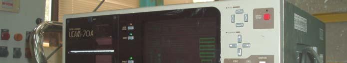


47 26 Figure 3.3 : Datalogger used for recording and printing out experimental data Figure 3.4 : Control box used for adjusting the speed of motor


48 27 Figure 3.5 : Sand rainer used in sand-rain technique Figure 3.6 : Enlarged base pier model pile with base angle, α = 3, α =45 and α = 6
49 Method Used to Obtain Loose Sand Packing Loose sand packing is obtained using sand-rain technique. The sand is deposited into tank from a height of 33 mm through a sand rainer. Figure 3.7 shows the variation of density index and dry unit weight with falling sand height. At a height of 33 mm, an average unit weight of γ d =14.8kN/m 3 is achieved. Sand Passing Sieve 2.36mm sieve size Density Index, I d Density Index Dry unit weight of soil Density Index Dry unit weight of soil, (kn/m 3 ) Height, H (cm) Figure 3.7 : Variations of density index and dry unit weight with falling sand height for sand passing 2.36mm sieve size (Chosun, 1999) 3.4 Method Used to Obtain Dense Sand Packing Dense sand packing is achieved through compaction of each 75 mm layer of sand using hand held compactor. Each layer of sand is compacted for 1 minutes to attain an average unit weight of γ d =16.9kN/m 3. Figure 3.8 show the variation of density index and dry unit weight with duration of mechanical compaction for each layer.
50 29 Sand Passing Sieve 2.36mm Sieve Size Density Index Dry unit weight of soil 17.1 Index Density, I d Dry unit weight of soil, (kn/m 3 ) Time, T (minutes) 16.6 Figure 3.8 : Variation of density index and dry unit weight with duration of mechanical compaction of sand passing 2.36mm sieve size (Chosun, 1999) 3.5 Uplift Test Procedures 1. The model pile is gripped firmly by steel ring connected to the pulling arm. 2. The model is lowered into the tank slowly and held vertically with the aid of spirit level. 3. The sand is deposited into the tank following sand placement technique of loose sand packing. 4. After the required depth of embedment is achieved, LVDT is placed at the top of the pile to measure the vertical displacement. 5. Load cell is mounted on the pulling arm and connected to data logger. 6. Motor and data logger is turned on. 7. Readings are taken at interval of 1 seconds and printed out by the data logger. 8. Pile is assumed to have encountered failure when peak value of uplift
51 3 load has reached. 9. The steps from 1 to 8 are repeated but sand placement technique of dense sand packing is used instead of loose sand packing. 1. The steps from 1 to 9 are repeated by using model piles with different parameter. Low Speed Motor Steel Rod Load Cell Data logger LVDT Pulling Arm Sand Pile Model Control Box Figure 3.9 : Schematic diagram for uplift tests
52 Failure Mechanism Test Procedures 1. The semicylindrical model pile is attached to a strand connected to motor winch. 2. The model is lowered into the tank slowly and kept in close contact with the glass wall of the tank. 3. It is held vertically with the aid of spirit level. 4. The sand is poured into the tank following sand placement technique of loose sand packing mm-thick horizontal layers of dyed sand are formed at 2 mm vertical intervals to enable failure mechanism in the sand mass around the model to be examined. 6. The model is pulled out at a constant rate of.6 mm/min. 7. The successive failure pattern is observed and photographed. 8. The steps from 1 to 7 are repeated by using sand placement technique of dense sand packing. Pulley 4mm 5mm Sand surface Steel angle 3mm dyed sand layer at an interval of 2mm semi-cylindrical model pile Loading cable Control box Motor 6mm 2m 2mm Figure 3.1 : Schematic diagram for failure mechanism tests


53 32 Figure 3.11 : Uplift test being carried out on model pile Figure 3.12 : Failure mechanism test set-up in the laboratory
54 Determination of Test Parameters The variables involved in the experiment are Q u, D b, D s, L, γ, α and I d. Fundamental dimensions are force and length. The variables measured by fundamental dimensions are Q u, D b, D s, L and γ. Meanwhile, α is dimensionless and I d is the ratio of Δ γ which is (γ -γmin) / (γ max - γ min ). Table 3.2 shows the physical and fundamental quantities involve in the relationship. In this case, there is m=2 fundamental dimensions required for measuring n = 6 kinds of quantity. According to G.A. Vignaux and J.L. Scott, different fundamental dimensions can be ascribed to different directions of length labelled as x, y, and z by using further dimensional analysis called ``vectorised'' or ``directional'' DA. Therefore, embedment length, L would have dimension Lz. Base Diameter, D b has an overall dimension of a single length, L but it shares dimensions along the x and y axis equally since it is measured horizontally. Thus, it is given a dimensional formula of L.5 x L.5 y. Volume, v would have dimensions L z L x L y rather than L 3. The equation relating all the variables have n-m = 4 dimensionless groups. Buckingham referred to these groups as π groups. Since π is a dimensionless group, the dimensions of each π are F L. The final equation obtained is in the form of : f (π 1, π 2, π 3, π 4 ) =. D b, L and γ have been chosen among the available variables, as the repeating variables. Total number of variables in each π is (3 + 1) = 4. Base on Buckingham s pi theorem, four sets of dimensionless products were developed using simulation of appropriate physical quantities. π 1 = D b -2 γ -1 L -1 Q u = Q γd u 2 b L π 2 = D b -1 D s = D D s b π 3 = α π 4 = I d Qu D s Hence, f (, 2, α, Id ) = γd L D b b
55 34 Q γd u 2 b L D s = f (,α, Id ) D b Q u = D 2 D s b Lγ f (,α, Id ) D b Where : Q u = net ultimate uplift capacity D b = diameter of the base D s = diameter of the shaft L = length of pile embedment γ = effective unit weight of sand α = angle of base I d = density index of sand Table 3.2. Physical quantities assumed to be involved in establishing the limiting uplift carrying capacity of uplift loaded enlarged base pile Material properties Pile Symbol Units Fundamentals Quantities Shaft diameter D s mm L Base diameter D b mm L Base angle α Length L mm L Uplift load Q n kn F Sand Bulk Unit Weight γ kn/m 3 FL -3 Density Index I d - - o -
56 35 CHAPTER IV RESULTS AND ANALYSIS 4.1 Failure Mechanism Studies The failure mechanism tests for enlarged base pile embedded in loose and dense sand were carried out in the glass box with 6 mm length, 25 mm width and 4 mm depth. A semi-cylindrical model pile having 1mm diameter base, 5 mm diameter shaft and 45 o base angle was buried in sand to a depth of 3 mm to achieve an embedment ratio of 3. Failure mechanism around the pile when it is subjected to successive uplift load will be observed. Figure 4.1 to Figure 4.4 illustrate failure mechanism developed around the pile in loose sand. On the other hand, sand movement due to vertical displacement of pile in dense sand can be observed in Figure 4.5 until Figure Failure Mechanism Studies for Enlarged Base Pile in Loose Sand Failure mechanism around the model in loose sand is not evident because the movement is only restricted to the pile-sand interface. The front view of semicylindrical model pile in loose sand before subjected to uplift load is illustrated in Figure 4.1. Figure 4.2 shows the little movement of sand at the toe of pile corresponding to the successive vertical displacement of the model. Once the running motor started to pull out the pile, passive zone was formed above the


57 36 enlarged base due to compression of sand. Arrow 1, 2 and 3 shows upward movement of dyed sand above the base. A void was formed at the bottom of the enlarged base with subsequent uplift movement. Further uplift movement of the pile pushed the sand mass upward as shown in Figure 4.3. The sand around the base of the pile collapsed to fill the void created underneath the pile. This can be seen in Figure 4.4. It is clear that pullout resistance is more governed by skin friction rather than shear resistance of sand. However, the height of skin friction affected is only about 2-3 times the shaft diameter above the bell. Due to loose condition, the low density of sand reduces the uplift resistance contributed by the weight of soil within the failure zone above the base. As a result, the peak uplift capacity of enlarged base pile in loose sand is lower than that in dense sand. Figure 4.1 : Front view of semi-cylindrical model pile before subjected to uplift load


58 Figure 4.2 : Early movement of sand mass at the toe of the pile formed void at the bottom of the pile buried in loose sand Figure 4.3 : Further movement of the pile pushed the sand mass upward


59 38 Figure 4.4 : Localize failure for enlarged base pile in loose sand Failure Mechanism Studies for Enlarged Base Pile in Dense Sand The front view of semi-cylindrical model pile in dense sand before subjected to uplift load is illustrated in Figure 4.5. Figure 4.6 illustrates early movement of sand mass at the toe of the pile that formed void at the bottom of the pile buried in dense sand. While the pile was continuously pulled out at a constant rate of.6 mm/min, the rupture planes are formed gradually above the base. The failure surfaces were seen much clearer in Figure 4.7 with further uplift movement of the pile. Arrow 1 and 2 shows upward movement of dyed sand above the base. The movements of sand involved are relatively higher than those associated with peak uplift load in uplift tests due to larger displacement. Figure 4.8 shows failure mechanism around the pile at a displacement of approximately 6 mm where sand around the base of pile collapsed to fill the void created. Active zone and passive zone were formed as shown in the figure. Failure surface above model pile
 and Rowe and Davis (1982).")

60 39 in dense sand was slightly curved and extend outwards from the corner of the foundation to the soil surface at an angle close to φ/2 to the vertical. This is similar to that reported by several other researchers such as Meyerhof and Adams (1968) and Rowe and Davis (1982). Balla (1961) also observed the similar failure mechanism for semi-cylindrical models of mushroom foundations for pylons. The failure surface in dense sand tends to diverge in the form of rupture plane. In contrast, failure zone in loose condition is more localized since most of the uplift resistance is contributed by skin friction. The pullout resistance of pile in dense sand is not governed by skin friction as in the case of loose sand. The collapse of sand below the base in dense condition when void was created due to continuous vertical displacement is not as evident as what it did in loose condition. This is because of the close contact and smaller void between sand particles. The model pile in dense sand was subjected to higher uplift load compared to loose sand and took longer time to have failure mechanism developed around it. Figure 4.5 : Front view of semi-cylindrical model pile before subjected to uplift load.


61 4 1 1 Figure 4.6 : Early movement of sand mass at the toe of the pile formed void at the bottom of the pile buried in dense sand 2 2 Figure 4.7 : Vertical uplift of the pile pushed the sand mass upward further and formed rupture planes above the base


62 41 A A B B A : Active Zone B : Passive Zone Figure 4.8 : Failure mechanism for enlarged base pile in dense sand 4.2 The Influence of Embedment Ratio on Uplift Capacity Embedment ratio is the most important factor that influences the uplift capacity of enlarged base pile. This can explain why almost all the existing design methods take into account the effect of embedment ratio. The uplift resistance of enlarged base pile increase with an increase of embedment ratio. Variation of uplift load with vertical displacement for pile with 1mm base diameter, 3mm shaft diameter and 3 o base angle buried in dense sand and loose sand in a range of L/Db = 1 to L/Db = 5 is given in Figure 4.9 and Figure 4.1 respectively. All enlarged base piles embedded in sand ranging from L/Db = 1 to L/Db = 5 reach their own maximum uplift load almost at the same vertical displacement but it is evident that uplift load corresponding to vertical displacement varies a lot based on the embedment ratio. Uplift load required to pull out the enlarged base pile increase with an increase of embedment ratio.
MATERIAL SELECTION IN MECHANICAL DESIGN OF CAR BUMPER NURUL AZWAN BIN ADNAN BACHELOR OF ENGINEERING UNIVERSITI MALAYSIA PAHANG
 MATERIAL SELECTION IN MECHANICAL DESIGN OF CAR BUMPER NURUL AZWAN BIN ADNAN BACHELOR OF ENGINEERING UNIVERSITI MALAYSIA PAHANG 50 mm Nurul Azwan Bin Adnan B. Eng. (Mech.) 2009 UMP 50 mm (20 gold-coloured
LEAK DETECTION IN PIPELINES USING WAVELET AND CEPSTRUM ANALYSIS ABDUL KADIR BIN SAMTA
 LEAK DETECTION IN PIPELINES USING WAVELET AND CEPSTRUM ANALYSIS ABDUL KADIR BIN SAMTA Report submitted in partial fulfillment of requirements for award of the Degree of Bachelor of Mechanical Engineering
BORANG PENGESAHAN STATUS TESIS
 UNIVERSITI TEKNOLOGI MALAYSIA PSZ 19:16 (Pind. 1/97) BORANG PENGESAHAN STATUS TESIS JUDUL: STUDIES ON PRINCIPAL COMPONENTS ANALYSIS AND ITS APPLICATION IN MULTIVARIATE DATA SESI PENGAJIAN: 2005/2006 Saya
Engineering FINAL YEAR PROJECT FACULTY OF ENGINEERING KNS 4222 EFFECT OF FINE CONTENT ON SHEAR STRENGTH OF SAND. Name : Kho Joo Tiong
 Engineering FINAL YEAR PROJECT FACULTY OF ENGINEERING KNS 4222 EFFECT OF FINE CONTENT ON SHEAR STRENGTH OF SAND Name : Kho Joo Tiong Matrics No. : 6670 Bachelor of Engineering with Honour (Civil engineering)
Uncertainty Evaluation for the Measurement of Gauge Block by Micrometer.
 UNIVERSITI TEKNIKAL MALAYSIA MELAKA Uncertainty Evaluation for the Measurement of Gauge Block by Micrometer. Thesis submitted in accordance with the requirements of the Universiti Teknikal Malaysia Melaka
SECONDARY BENDING MOMENT OF TRAPEZOID WEB BEAM UNDER SHEAR LOADING FONG SHIAU WEEN
 ii SECONDARY BENDING MOMENT OF TRAPEZOID WEB BEAM UNDER SHEAR LOADING FONG SHIAU WEEN A project report submitted in partial fulfillment of the requirements for the award of the degree of Master of Engineering
CHANGE DETECTION ON KLANG AREA USING LANDSAT 5-TM DATA NURAMALINA BINTI MAT SERAH UNIVERSITI TEKNIKAL MALAYSIA MELAKA
 CHANGE DETECTION ON KLANG AREA USING LANDSAT 5-TM DATA NURAMALINA BINTI MAT SERAH UNIVERSITI TEKNIKAL MALAYSIA MELAKA BORANG PENGESAHAN STATUS TESIS* JUDUL : SESI PENGAJIAN : 2011 _/ 2012 _ Saya CHANGE
Sample Chapter HELICAL ANCHORS IN SAND 6.1 INTRODUCTION
 6 ELICAL ANCORS IN SAN At the present time, limited studies on helical anchors are available, the results of which can be used to estimate their ultimate uplift capacity. In many instances, the ultimate
UNIVERSITI TEKNOLOGI MALAYSIA
 Lampiran 20 UNIVERSITI TEKNOLOGI MALAYSIA UTM/RMC/F/0024 (1998) BORANG PENGESAHAN LAPORAN AKHIR PENYELIDIKAN TAJUK PROJEK : CONJUGACY AND ORDER CLASSES OF 2-GENERATOR p-group OF NILPOTENCY CLASS 2 Saya
II I, II li li I! lil II! Mil II i; ii ;: 3 OOOO /. 7
 PER PUS 7 AKAAfJ KUi T T HO II I, II li li I! lil II! Mil II i; ii ;: 3 OOOO 0010255/. 7 KOLEJ UNIVERSm TEKNOLOGI TUN HUSSEIN ONN BORANG PENGESAHAN STATUS TESIS* JUDUL: ROBUST POWER SYSTEM STABILISER DESIGN
Three Dimensional Lower Bound Solutions for the Stability of Plate Anchors in Sand
 Three Dimensional Lower Bound Solutions for the Stability of Plate Anchors in Sand Richard S Merifield Scott W Sloan Andrei V Lyamin richard.merifield@usq.edu.au http://www.usq.edu.au/users/merifield/
A WIDEBAND OMNIDIRECTIONAL PLANAR MICROSTRIP ANTENNA FOR WLAN APPLICATION USING GRAPHENE MOHD REDZUAN BIN SHAKIL AHMAD
 A WIDEBAND OMNIDIRECTIONAL PLANAR MICROSTRIP ANTENNA FOR WLAN APPLICATION USING GRAPHENE MOHD REDZUAN BIN SHAKIL AHMAD This Report Is Submitted In Fulfilment of Requirement for the Bachelor Degree of Electronic
ULTRASONIC PULSE VELOCITY (UPV) TEST ON CONCRETE UNDER CO:MPRESSION: A STUDY ON EFFECT OF ASPECT RATIO
 TEST ON CONCRETE UNDER CO:MPRESSION: A STUDY ON EFFECT OF ASPECT RATIO") ULTRASONIC PULSE VELOCITY (UPV) TEST ON CONCRETE UNDER CO:MPRESSION: A STUDY ON EFFECT OF ASPECT RATIO Chai Peng How Bachelor of Engineering with Honours TA (Civil Engineering) 418.9 2005 C434 2005 UNlVERSITI
ULTRASONIC PULSE VELOCITY (UPV) TEST ON CONCRETE UNDER CO:MPRESSION: A STUDY ON EFFECT OF ASPECT RATIO Chai Peng How Bachelor of Engineering with Honours TA (Civil Engineering) 418.9 2005 C434 2005 UNlVERSITI
Faculty of Electronic and Computer Engineering Universiti Teknikal Malaysia Melaka
 VELOCITY MEASUREMENT OF FLOWING OBJECT USING INFRARED SENSOR NURUL FAZLIYANI BINTI RUSLI This report is submitted in partial fulfillment of the requirements for the award of Bachelor of Electronic Engineering
EXTREME RAINFALL PATTERNS FOR SG. SARAWAK AND SAMARAHAN RIVER BASINS
 EXTREME RAINFALL PATTERNS FOR SG. SARAWAK AND SAMARAHAN RIVER BASINS Wan Faizurah Binti Wan Ahmad Bachelor of Engineering with Honours (Civil Engineering) 2009 UNIVERSITI MALAYSIA SARAWAK BORANG PENGESAHAN
BORANG PENGESAHAN STATUS TESIS υ
 UNIVERSITI TEKNOLOGI MALAYSIA PSZ 19:16 (Pind. 1/97) BORANG PENGESAHAN STATUS TESIS υ JUDUL : JAR TEST: ONE-FACTOR-AT A-TIME VERSUS RESPONSE SURFACE DESIGN SESI PENGAJIAN: 2005/2006 Saya ALBRAHAM ENGGONG
BEARING CAPACITY, COMPARISON OF RESULTS FROM PLAXIS 2D AND EMPIRICAL MODEL HONG PUAN YEE
 BEARING CAPACITY, COMPARISON OF RESULTS FROM PLAXIS 2D AND EMPIRICAL MODEL HONG PUAN YEE A project report submitted in partial fulfilment of the requirements for the award of the degree of Master of Engineering
UNIVERSITI TEKNIKAL MALAYSIA MELAKA
 UNIVERSITI TEKNIKAL MALAYSIA MELAKA DESIGN AND DEVELOPMENT OF PIEZOELECTRIC ENERGY HARVESTING SYSTEM ON THE STREET LIGHT This report submitted in accordance with requirement of the Universiti Teknikal
EFFECT OF ROCK MASS PROPERTIES ON SKIN FRICTION OF ROCK SOCKET. YUSLIZA BINTI ALIAS UNIVERSITI TEKNOLOGI MALAYSIA
 EFFECT OF ROCK MASS PROPERTIES ON SKIN FRICTION OF ROCK SOCKET. YUSLIZA BINTI ALIAS UNIVERSITI TEKNOLOGI MALAYSIA EFFECT OF ROCK MASS PROPERTIES ON SKIN FRICTION OF ROCK SOCKET. YUSLIZA BINTI ALIAS A project
Analysis of Inclined Strip Anchors in Sand Based on the Block Set Mechanism
 Analysis of Inclined Strip Anchors in Sand Based on the Block Set Mechanism S. B. Yu 1,a, J. P. Hambleton 1,b, and S. W. Sloan 1,c 1 ARC Centre of Excellence for Geotechnical Science and Engineering, The
ENGINEERING PROPERTIES OF OLDER ALLUVIUM BADEE ABDULQAWI HAMOOD ALSHAMERI. Universiti Teknologi Malaysia
 BADEE ABDULQAWI HAMOOD ALSHAMERI MASTER OF ENGINEERING (CIVIL GEOTECHNICS) 2010 UTM ENGINEERING PROPERTIES OF OLDER ALLUVIUM BADEE ABDULQAWI HAMOOD ALSHAMERI Universiti Teknologi Malaysia DECEMBER 2010
The Bearing Capacity of Soils. Dr Omar Al Hattamleh
 The Bearing Capacity of Soils Dr Omar Al Hattamleh Example of Bearing Capacity Failure Omar Play the move of bearing Capacity failure The Philippine one Transcona Grain Silos Failure - Canada The Bearing
UNDRAINED SHEAR STRENGTH OF SOFT CLAY REINFORCE WITH SINGLE 16MM DIAMETER ENCAPSULATED BOTTOM ASH COLUMN NABILAH BINTI MD MASHOD FAKEH
 1 UNDRAINED SHEAR STRENGTH OF SOFT CLAY REINFORCE WITH SINGLE 16MM DIAMETER ENCAPSULATED BOTTOM ASH COLUMN NABILAH BINTI MD MASHOD FAKEH B. ENG (HONS.) CIVIL ENGINEERING UNIVERSITI MALAYSIA PAHANG 1 UNIVERSITI
ULTIMATE STRENGTH ANALYSIS OF SHIPS PLATE DUE TO CORROSION ZULFAQIH BIN LAZIM
 i ULTIMATE STRENGTH ANALYSIS OF SHIPS PLATE DUE TO CORROSION ZULFAQIH BIN LAZIM A project report submitted in partial fulfillment of the requirement for the award of the degree of Master of Engineering
Chapter (11) Pile Foundations
 Pile Foundations") Chapter (11) Introduction Piles are structural members that are made of steel, concrete, or timber. They are used to build pile foundations (classified as deep foundations) which cost more than shallow
Chapter (11) Introduction Piles are structural members that are made of steel, concrete, or timber. They are used to build pile foundations (classified as deep foundations) which cost more than shallow
Introduction to Soil Mechanics
 Introduction to Soil Mechanics Sela Sode and Colin Jones WILEY Blackwell Contents Preface Dedication and Acknowledgments List of Symbols Soil Structure 1.1 Volume relationships 1.1.1 Voids ratio (e) 1.1.2
STABILITY AND SIMULATION OF A STANDING WAVE IN POROUS MEDIA LAU SIEW CHING UNIVERSTI TEKNOLOGI MALAYSIA
 STABILITY AND SIMULATION OF A STANDING WAVE IN POROUS MEDIA LAU SIEW CHING UNIVERSTI TEKNOLOGI MALAYSIA I hereby certify that I have read this thesis and in my view, this thesis fulfills the requirement
EMPIRICAL STRENQTH ENVELOPE FOR SHALE NUR 'AIN BINTI MAT YUSOF
 EMPIRICAL STRENQTH ENVELOPE FOR SHALE NUR 'AIN BINTI MAT YUSOF A project report submitted in partial fulfilment oftbe requirements for the award ofthe degree of Master ofengineering (Geotechnics) Faculty
CHAPTER 8 CALCULATION THEORY
 CHAPTER 8 CALCULATION THEORY. Volume 2 CHAPTER 8 CALCULATION THEORY Detailed in this chapter: the theories behind the program the equations and methods that are use to perform the analyses. CONTENTS CHAPTER
10. Chattopadhyay B.C. and Pise P.J. (1986), Breakout Resistance of Horizontal Anchors in Sand, Soils and Foundations, Vol. 26, No. 4, pp
, Breakout Resistance of Horizontal Anchors in Sand, Soils and Foundations, Vol. 26, No. 4, pp") 266 REFERENCES 1. Adams J.I. and Hayes D.C. (1967), The Uplift Capacity of Shallow Foundation, Ontario Hydro Research Quarterly, Vol. 19, No. 1, pp. 1-13. 2. Andreadis A., Harvey R.C. and Burley E. (1981),
266 REFERENCES 1. Adams J.I. and Hayes D.C. (1967), The Uplift Capacity of Shallow Foundation, Ontario Hydro Research Quarterly, Vol. 19, No. 1, pp. 1-13. 2. Andreadis A., Harvey R.C. and Burley E. (1981),
Chapter (3) Ultimate Bearing Capacity of Shallow Foundations
 Ultimate Bearing Capacity of Shallow Foundations") Chapter (3) Ultimate Bearing Capacity of Shallow Foundations Introduction To perform satisfactorily, shallow foundations must have two main characteristics: 1. They have to be safe against overall shear
Chapter (3) Ultimate Bearing Capacity of Shallow Foundations Introduction To perform satisfactorily, shallow foundations must have two main characteristics: 1. They have to be safe against overall shear
EFFECT OF FINES CONTENT AND PLASTICITY ON LIQUEFACTION SUSCEPTIBILITY OF SAND MATRIX SOILS TAN CHOY SOON
 EFFECT OF FINES CONTENT AND PLASTICITY ON LIQUEFACTION SUSCEPTIBILITY OF SAND MATRIX SOILS TAN CHOY SOON A thesis submitted in fulfilment of the requirements for the award of the degree of Doctor ofphilosophy
UPLIFT CAPACITY OF PILES SUBJECTED TO INCLINED LOAD IN TWO LAYERED SOIL. Dr. Sunil S. Pusadkar 1, Sachin Ghormode 2 ABSTRACT
 50 th IGC 50 th INDIAN GEOTECHNICAL CONFERENCE 17 th 19 th DECEMBER 2015, Pune, Maharashtra, India Venue: College of Engineering (Estd. 1854), Pune, India UPLIFT CAPACITY OF PILES SUBJECTED TO INCLINED
ALTERNATIVE STRIP METHOD FOR A LATERALLY DRIFTING SHIP IN WAVES MUHAMAD BIN RAMLI
 iii ALTERNATIVE STRIP METHOD FOR A LATERALLY DRIFTING SHIP IN WAVES MUHAMAD BIN RAMLI A dissertation submitted in partial fulfilment of the requirements for the award of the degree of Master of Engineering
9.13 Fixed Earth-Support Method for Penetration into Sandy Soil
 476 Chapter 9: Sheet Pile Walls 9.13 Fixed Earth-Support Method for Penetration into y Soil When using the fixed earth support method, we assume that the toe of the pile is restrained from rotating, as
ARTIFICIAL NEURAL NETWORK AND KALMAN FILTER APPROACHES BASED ON ARIMA FOR DAILY WIND SPEED FORECASTING OSAMAH BASHEER SHUKUR
 i ARTIFICIAL NEURAL NETWORK AND KALMAN FILTER APPROACHES BASED ON ARIMA FOR DAILY WIND SPEED FORECASTING OSAMAH BASHEER SHUKUR A thesis submitted in fulfilment of the requirements for the award of the
INTRODUCTION TO STATIC ANALYSIS PDPI 2013
 INTRODUCTION TO STATIC ANALYSIS PDPI 2013 What is Pile Capacity? When we load a pile until IT Fails what is IT Strength Considerations Two Failure Modes 1. Pile structural failure controlled by allowable
UNIVERSITI PUTRA MALAYSIA
 UNIVERSITI PUTRA MALAYSIA SOLUTIONS OF DIOPHANTINE EQUATION FOR PRIMES p, 2 p 13 SHAHRINA BT ISMAIL IPM 2011 10 SOLUTIONS OF DIOPHANTINE EQUATION FOR PRIMES, By SHAHRINA BT ISMAIL Thesis Submitted to the
ADSORPTION OF ARSENATE BY HEXADECYLPYRIDINIUM BROMIDE MODIFIED NATURAL ZEOLITE MOHD AMMARUL AFFIQ BIN MD BUANG UNIVERSITI TEKNOLOGI MALAYSIA
 ADSORPTION OF ARSENATE BY HEXADECYLPYRIDINIUM BROMIDE MODIFIED NATURAL ZEOLITE MOHD AMMARUL AFFIQ BIN MD BUANG UNIVERSITI TEKNOLOGI MALAYSIA ADSORPTION OF ARSENATE BY HEXADECYLPYRIDINIUM BROMIDE MODIFIED
EFFECT OF NOZZLE ANGLE ON JET IMPINGEMENT COOLING SYSTEM KHAIDER BIN ABU BAKAR
 EFFECT OF NOZZLE ANGLE ON JET IMPINGEMENT COOLING SYSTEM KHAIDER BIN ABU BAKAR Report submitted in fulfilment of the requirements for the award of the degree of Bachelor of Mechanical Engineering Faculty
DYNAMIC SIMULATION OF COLUMNS CONSIDERING GEOMETRIC NONLINEARITY MOSTAFA MIRSHEKARI
 DYNAMIC SIMULATION OF COLUMNS CONSIDERING GEOMETRIC NONLINEARITY MOSTAFA MIRSHEKARI A project report submitted in partial fulfillment of the requirements for the award of the degree of Master of Engineering
TABLE OF CONTENTS CHAPTER TITLE PAGE TITLE PAGE DECLARATION DEDIDATION ACKNOWLEDGEMENTS ABSTRACT ABSTRAK
 TABLE OF CONTENTS CHAPTER TITLE PAGE TITLE PAGE DECLARATION DEDIDATION ACKNOWLEDGEMENTS ABSTRACT ABSTRAK TABLE OF CONTENTS LIST OF TABLE LIST OF FIGURES LIST OF SYMBOLS LIST OF APENDICES i ii iii iv v
INDIRECT TENSION TEST OF HOT MIX ASPHALT AS RELATED TO TEMPERATURE CHANGES AND BINDER TYPES AKRIMA BINTI ABU BAKAR
 INDIRECT TENSION TEST OF HOT MIX ASPHALT AS RELATED TO TEMPERATURE CHANGES AND BINDER TYPES AKRIMA BINTI ABU BAKAR A project report submitted in partial fulfillment of the requirements for the award of
A study on the bearing capacity of steel pipe piles with tapered tips
 Japanese Geotechnical Society Special Publication The 6th Japan-China Geotechnical Symposium A study on the bearing capacity of steel pipe piles with tapered tips Hironobu Matsumiya i), Yoshiro Ishihama
DETECTION OF STRUCTURAL DEFORMATION FROM 3D POINT CLOUDS JONATHAN NYOKA CHIVATSI UNIVERSITI TEKNOLOGI MALAYSIA
 DETECTION OF STRUCTURAL DEFORMATION FROM 3D POINT CLOUDS JONATHAN NYOKA CHIVATSI UNIVERSITI TEKNOLOGI MALAYSIA DETECTION OF STRUCTURAL DEFORMATION FROM 3D POINT CLOUDS JONATHAN NYOKA CHIVATSI A project
D E S P AND DEVELOPMENT OF AN SAGA COMPLIANT MAGNETIC OBSERVATORY
 D E S P AND DEVELOPMENT OF AN SAGA COMPLIANT MAGNETIC OBSERVATORY mohd mm m omm LINIVERS'T! YUfi HUSSEiN OHN MALAYSIA PERPUSTAKAAN UTHM ^30000002103496* UNIVERSITI TUN HUSSEIN ONN MALAYSIA BORANG PENGESAHAN
INFLUENCES OF GROUNDWATER, RAINFALL, AND TIDES ON BEACH PROFILES CHANGES AT DESARU BEACH FARIZUL NIZAM BIN ABDULLAH
 INFLUENCES OF GROUNDWATER, RAINFALL, AND TIDES ON BEACH PROFILES CHANGES AT DESARU BEACH FARIZUL NIZAM BIN ABDULLAH A project report submitted in partial fulfillment of the requirements for the award of
A COMPUTATIONAL FLUID DYNAMIC FRAMEWORK FOR MODELING AND SIMULATION OF PROTON EXCHANGE MEMBRANE FUEL CELL HAMID KAZEMI ESFEH
 A COMPUTATIONAL FLUID DYNAMIC FRAMEWORK FOR MODELING AND SIMULATION OF PROTON EXCHANGE MEMBRANE FUEL CELL HAMID KAZEMI ESFEH A thesis submitted in fulfilment of the requirements for the award ofthe degree
THE DETERMINATION OF SHEAR PROPERTIES OF BRITTLE MATERIALS USING ARCAN TEST METHOD FAHIS BIN TUMIN
 THE DETERMINATION OF SHEAR PROPERTIES OF BRITTLE MATERIALS USING ARCAN TEST METHOD FAHIS BIN TUMIN UNIVERSITI TEKNOLOGI MALAYSIA PSZ 19:16 (Pind. 1/97) UNIVERSITI TEKNOLOGI MALAYSIA BORANG PENGESAHAN STATUS
NUMERICAL INVESTIGATION OF TURBULENT NANOFLUID FLOW EFFECT ON ENHANCING HEAT TRANSFER IN STRAIGHT CHANNELS DHAFIR GIYATH JEHAD
 1 NUMERICAL INVESTIGATION OF TURBULENT NANOFLUID FLOW EFFECT ON ENHANCING HEAT TRANSFER IN STRAIGHT CHANNELS DHAFIR GIYATH JEHAD UNIVERSITI TEKNOLOGI MALAYSIA 3 NUMERICAL INVESTIGATION OF TURBULENT NANOFLUID
THE DEVELOPMENT OF PORTABLE SENSOR TO DETERMINE THE FRESHNESS AND QUALITY OF FRUITS USING CAPACITIVE TECHNIQUE LAI KAI LING
 i THE DEVELOPMENT OF PORTABLE SENSOR TO DETERMINE THE FRESHNESS AND QUALITY OF FRUITS USING CAPACITIVE TECHNIQUE LAI KAI LING A report submitted in partial fulfillment of the requirements for the award
ANOLYTE SOLUTION GENERATED FROM ELECTROCHEMICAL ACTIVATION PROCESS FOR THE TREATMENT OF PHENOL
 ANOLYTE SOLUTION GENERATED FROM ELECTROCHEMICAL ACTIVATION PROCESS FOR THE TREATMENT OF PHENOL By ZAULFIKAR Thesis Submitted to the School of Graduate Studies, Universiti Putra Malaysia, in Fulfilment
1111 IIIII;lrrnlrlJir!WIlli' " "
 1111 IIIII;lrrnlrlJir!WIlli' 111111 "30000002103398" SIMULATION OF PAVEMENT DEFORMATIONS FOR DIFFERENT APPROACH SLABS CONCEPT CONSTRUCTED ON BATU PAHAT SOFT CLAY (BPSC) MOHD NAZRIN MOHD DAUD This dissertation
Foundation Engineering Prof. Dr. N. K. Samadhiya Department of Civil Engineering Indian Institute of Technology Roorkee
 Foundation Engineering Prof. Dr. N. K. Samadhiya Department of Civil Engineering Indian Institute of Technology Roorkee Module - 01 Lecture - 01 Shallow Foundation (Refer Slide Time: 00:19) Good morning.
BACKFILL AND INTERFACE CHARACTERISTICS
 Chapter 5 BACKFILL AND INTERFACE CHARACTERISTICS This chapter introduces the properties of backfill and the distribution of soil density in the soil bin. The interface characteristics between the backfill
Deep Foundations 2. Load Capacity of a Single Pile
 Deep Foundations 2 Load Capacity of a Single Pile All calculations of pile capacity are approximate because it is almost impossible to account for the variability of soil types and the differences in the
Reinforced Soil Structures Reinforced Soil Walls. Prof K. Rajagopal Department of Civil Engineering IIT Madras, Chennai
 Geosynthetics and Reinforced Soil Structures Reinforced Soil Walls continued Prof K. Rajagopal Department of Civil Engineering IIT Madras, Chennai e-mail: gopalkr@iitm.ac.inac in Outline of the Lecture
Evaluation of short piles bearing capacity subjected to lateral loading in sandy soil
 Evaluation of short piles bearing capacity subjected to lateral loading in sandy soil [Jafar Bolouri Bazaz, Javad Keshavarz] Abstract Almost all types of piles are subjected to lateral loads. In many cases,
Foundation Engineering Prof. Dr N.K. Samadhiya Department of Civil Engineering Indian Institute of Technology Roorkee
 Foundation Engineering Prof. Dr N.K. Samadhiya Department of Civil Engineering Indian Institute of Technology Roorkee Module 01 Lecture - 03 Shallow Foundation So, in the last lecture, we discussed the
UNIVERSITI TEKNIKAL MALAYSIA MELAKA
 UNIVERSITI TEKNIKAL MALAYSIA MELAKA STUDY OF EPOXY RESIN BONDING PROCESS OF ALUMINUM ALLOY : CHEMICAL PICKLING PROCESS (HYDROCHLORIC ACID) This report submitted in accordance with the requirements of the
DESIGN OF DOWELS FOR SHEAR TRANSFER AT THE INTERFACE BETWEEN CONCRETE CAST AT DIFFERENT TIMES: A CASE STUDY
 DESIGN OF DOWELS FOR SHEAR TRANSFER AT THE INTERFACE BETWEEN CONCRETE CAST AT DIFFERENT TIMES: A CASE STUDY Samayamanthree Mudiyanselage Premasiri Karunarathna 118614J Degree of Master of Engineering in
Pullout Tests of Geogrids Embedded in Non-cohesive Soil
 Archives of Hydro-Engineering and Environmental Mechanics Vol. 51 (2004), No. 2, pp. 135 147 Pullout Tests of Geogrids Embedded in Non-cohesive Soil Angelika Duszyńska, Adam F. Bolt Gdansk University of
GEOTECHNICAL ENGINEERING ECG 503 LECTURE NOTE ANALYSIS AND DESIGN OF RETAINING STRUCTURES
 GEOTECHNICAL ENGINEERING ECG 503 LECTURE NOTE 07 3.0 ANALYSIS AND DESIGN OF RETAINING STRUCTURES LEARNING OUTCOMES Learning outcomes: At the end of this lecture/week the students would be able to: Understand
ERODABLE DAM BREACHING PATTERNS DUE TO OVERTOPPING NOR AIN BINTI MAT LAZIN UNIVERSITI TEKNOLOGI MALAYSIA
 ERODABLE DAM BREACHING PATTERNS DUE TO OVERTOPPING NOR AIN BINTI MAT LAZIN UNIVERSITI TEKNOLOGI MALAYSIA ERODABLE DAM BREACHING PATTERNS DUE TO OVERTOPPING NOR AIN BINTI MAT LAZIN A thesis submitted in
Cavity Expansion Methods in Geomechanics
 Cavity Expansion Methods in Geomechanics by Hai-Sui Yu School of Civil Engineering, University of Nottingham, U. K. KLUWER ACADEMIC PUBLISHERS DORDRECHT / BOSTON / LONDON TABLE OF CONTENTS Foreword Preface
Soil Mechanics Prof. B.V.S. Viswanathan Department of Civil Engineering Indian Institute of Technology, Bombay Lecture 51 Earth Pressure Theories II
 Soil Mechanics Prof. B.V.S. Viswanathan Department of Civil Engineering Indian Institute of Technology, Bombay Lecture 51 Earth Pressure Theories II Welcome to lecture number two on earth pressure theories.
SHEAR STRENGTH I YULVI ZAIKA
 SHEAR STRENGTH I YULVI ZAIKA MATERI Keruntuhan mohr coulomb, stress paths, kuat geser tanah non kohesif dan kohesif, evaluasi kuat geser di lapangan, tegangan normal dan tegangan geser pada sebuah bidang
SYSTEM IDENTIFICATION MODEL AND PREDICTIVE FUNCTIONAL CONTROL OF AN ELECTRO-HYDRAULIC ACTUATOR SYSTEM NOOR HANIS IZZUDDIN BIN MAT LAZIM
 iii SYSTEM IDENTIFICATION MODEL AND PREDICTIVE FUNCTIONAL CONTROL OF AN ELECTRO-HYDRAULIC ACTUATOR SYSTEM NOOR HANIS IZZUDDIN BIN MAT LAZIM A project report submitted in fulfilment of the requirements
1IIIIIIIiillll!lllIi!llIiilll!illliIIIlIIIJIIIIJIIIIII:::iIJIIII illir
 PERPUSTAKAAN UTHM 1IIIIIIIiillll!lllIi!llIiilll!illliIIIlIIIJIIIIJIIIIII:::iIJIIII illir '30000001883498' KOLEJ UNIVERSITI TEKNOLOGI TUN HUSSEIN ONN BORANG PENGESAHAN STATUS TESIS JUDUL: FORENSIC STUDY
INTI COLLEGE MALAYSIA
 EGC373 (F) / Page 1 of 5 INTI COLLEGE MALAYSIA UK DEGREE TRANSFER PROGRAMME INTI ADELAIDE TRANSFER PROGRAMME EGC 373: FOUNDATION ENGINEERING FINAL EXAMINATION : AUGUST 00 SESSION This paper consists of
MULTISTAGE ARTIFICIAL NEURAL NETWORK IN STRUCTURAL DAMAGE DETECTION GOH LYN DEE
 MULTISTAGE ARTIFICIAL NEURAL NETWORK IN STRUCTURAL DAMAGE DETECTION GOH LYN DEE A thesis submitted in fulfilment of the requirements for the award of the degree of Doctor of Philosophy (Civil Engineering)
TABLE OF CONTENTS SECTION TITLE PAGE 2 PRINCIPLES OF SEISMIC ISOLATION OF BRIDGES 3
 TABLE OF CONTENTS SECTION TITLE PAGE 1 INTRODUCTION 1 2 PRINCIPLES OF SEISMIC ISOLATION OF BRIDGES 3 3 ANALYSIS METHODS OF SEISMICALLY ISOLATED BRIDGES 5 3.1 Introduction 5 3.2 Loadings for the Analysis
ROCK SHAFT RESISTANCE OF BORED PILES SOCKETED INTO DECOMPOSED MALAYSIA GRANITE RAJA SHAHROM NIZAM SHAH BIN RAJA SHOIB UNIVERSITI TEKNOLOGI MALAYSIA
 ROCK SHAFT RESISTANCE OF BORED PILES SOCKETED INTO DECOMPOSED MALAYSIA GRANITE RAJA SHAHROM NIZAM SHAH BIN RAJA SHOIB UNIVERSITI TEKNOLOGI MALAYSIA ROCK SHAFT RESISTANCE OF BORED PILES SOCKETED INTO DECOMPOSED
ULTIMATE BEARING CAPACITY OF ECCENTRICALLY LOADED STRIP FOUNDATION ON SAND REINFORCED WITH GEOGRIDS
 ULTIMATE BEARING CAPACITY OF ECCENTRICALLY LOADED STRIP FOUNDATION ON SAND REINFORCED WITH GEOGRIDS C. R. Patra National Institute of Technology, Rourkela, India B. M. Das California State University,
EFFECT OF GRAPHENE OXIDE (GO) IN IMPROVING THE PERFORMANCE OF HIGH VOLTAGE INSULATOR NUR FARAH AIN BINTI ISA UNIVERSITI TEKNOLOGI MALAYSIA
 IN IMPROVING THE PERFORMANCE OF HIGH VOLTAGE INSULATOR NUR FARAH AIN BINTI ISA UNIVERSITI TEKNOLOGI MALAYSIA") 1 EFFECT OF GRAPHENE OXIDE (GO) IN IMPROVING THE PERFORMANCE OF HIGH VOLTAGE INSULATOR NUR FARAH AIN BINTI ISA UNIVERSITI TEKNOLOGI MALAYSIA EFFECT OF GRAPHENE OXIDE (GO) IN IMPROVING THE PERFORMANCE OF
1 EFFECT OF GRAPHENE OXIDE (GO) IN IMPROVING THE PERFORMANCE OF HIGH VOLTAGE INSULATOR NUR FARAH AIN BINTI ISA UNIVERSITI TEKNOLOGI MALAYSIA EFFECT OF GRAPHENE OXIDE (GO) IN IMPROVING THE PERFORMANCE OF
Energy Method for Predicting Installation Torque of Helical Foundations and Anchors
 Revised August 10, 2001. Original published in New Technological and Design Developments in Deep Foundations, Proceedings of GeoDenver 2000, Norman D. Dennis, Jr., Ray Castelli, and Michael W. O Neill,
The theories to estimate lateral earth pressure due to a strip surcharge loading will
 Chapter LITERATURE REVIEW The theories to estimate lateral earth pressure due to a strip surcharge loading will be introduced in this chapter. Commonly geotechnical engineers apply the equations suggested
WIND TUNNEL TEST TO INVESTIGATE TRANSITION TO TURBULENCE ON WIND TURBINE AIRFOIL MAHDI HOZHABRI NAMIN UNIVERSITI TEKNOLOGI MALAYSIA
 WIND TUNNEL TEST TO INVESTIGATE TRANSITION TO TURBULENCE ON WIND TURBINE AIRFOIL MAHDI HOZHABRI NAMIN UNIVERSITI TEKNOLOGI MALAYSIA WIND TUNNEL TEST TO INVESTIGATE TRANSITION TO TURBULENCE ON WIND TURBINE
COVRE OPTIMIZATION FOR IMAGE STEGANOGRAPHY BY USING IMAGE FEATURES ZAID NIDHAL KHUDHAIR
 COVRE OPTIMIZATION FOR IMAGE STEGANOGRAPHY BY USING IMAGE FEATURES ZAID NIDHAL KHUDHAIR A dissertation submitted in partial fulfillment of the requirements for the award of the degree of Master of Science
Foundations with D f equal to 3 to 4 times the width may be defined as shallow foundations. TWO MAIN CHARACTERISTICS ULTIMATE BEARING CAPACITY
 oundation Analysis oundations with D f eual to 3 to 4 times the width may be defined as shallow foundations. TWO MAI CHARACTERISTICS o Safe against overall shear failure o Cannot undergo excessive displacement,
DESIGN AND DETAILING OF COUNTERFORT RETAINING WALL
 DESIGN AND DETAILING OF COUNTERFORT RETAINING WALL When the height of the retaining wall exceeds about 6 m, the thickness of the stem and heel slab works out to be sufficiently large and the design becomes
g e o p i e r u p l i f t r e s i s t a n c e
 geopier foundation co inc t e c h n i c a l b u l l e t i n N o. 3 g e o p i e r u p l i f t r e s i s t a n c e This Technical Bulletin discusses the behavior of Geopier Rammed Aggregate Pier elements
Chapter (6) Geometric Design of Shallow Foundations
 Geometric Design of Shallow Foundations") Chapter (6) Geometric Design of Shallow Foundations Introduction As we stated in Chapter 3, foundations are considered to be shallow if if [D (3 4)B]. Shallow foundations have several advantages: minimum
Chapter (6) Geometric Design of Shallow Foundations Introduction As we stated in Chapter 3, foundations are considered to be shallow if if [D (3 4)B]. Shallow foundations have several advantages: minimum
Chapter (4) Ultimate Bearing Capacity of Shallow Foundations (Special Cases)
 Ultimate Bearing Capacity of Shallow Foundations (Special Cases)") Chapter (4) Ultimate earing Capacity of Shallow Foundations (Special Cases) Ultimate.C. of Shallow Foundations (Special Cases) Introduction The ultimate bearing capacity theories discussed in Chapter 3
Chapter (4) Ultimate earing Capacity of Shallow Foundations (Special Cases) Ultimate.C. of Shallow Foundations (Special Cases) Introduction The ultimate bearing capacity theories discussed in Chapter 3
INSTRUCTION: This section consists of TWO (2) structured questions. Answer ALL questions.
 structured questions. Answer ALL questions.") SECTION A: 50 MARKS BAHAGIAN A: 50 MARKAH INSTRUCTION: This section consists of TWO (2) structured questions. Answer ALL questions. ARAHAN : Bahagian ini mengandungi DUA (2) soalan berstruktur. Jawab SEMUA
SECTION A: 50 MARKS BAHAGIAN A: 50 MARKAH INSTRUCTION: This section consists of TWO (2) structured questions. Answer ALL questions. ARAHAN : Bahagian ini mengandungi DUA (2) soalan berstruktur. Jawab SEMUA
EFFECT OF SOIL TYPE ON SEISMIC PERFROMANCE OF REINFORCED CONCRETE SCHOOL BUILDING
 EFFECT OF SOIL TYPE ON SEISMIC PERFROMANCE OF REINFORCED CONCRETE SCHOOL BUILDING NUR AMIRAH BINTI MOHD NASAI B. ENG (HONS.) CIVIL ENGINEERING UNIVERSITI MALAYSIA PAHANG SUPERVISOR S DECLARATION I hereby
UNIVERSITI TUN HUSSEIN ONN MALAYSIA BORANG PENGESAHAN STATUS TESIS SESI PENGAJIAN: 2005/2007
 UNIVERSITI TUN HUSSEIN ONN MALAYSIA BORANG PENGESAHAN STATUS TESIS JUDUL: Numerical Simulation of Jet Impingement on a Smooth Concave Surface SESI PENGAJIAN: 2005/2007 Saya SUZAIRIN BIN MD SERI (770520-01-7385)
FRAGMENT REWEIGHTING IN LIGAND-BASED VIRTUAL SCREENING ALI AHMED ALFAKIABDALLA ABDELRAHIM
 i FRAGMENT REWEIGHTING IN LIGAND-BASED VIRTUAL SCREENING ALI AHMED ALFAKIABDALLA ABDELRAHIM A thesis submitted in fulfilment of the requirements for the award of the degree of Doctor of Philosophy (Computer
EFFECTS OF Ni 3 Ti (DO 24 ) PRECIPITATES AND COMPOSITION ON Ni-BASED SUPERALLOYS USING MOLECULAR DYNAMICS METHOD
 PRECIPITATES AND COMPOSITION ON Ni-BASED SUPERALLOYS USING MOLECULAR DYNAMICS METHOD") EFFECTS OF Ni 3 Ti (DO 24 ) PRECIPITATES AND COMPOSITION ON Ni-BASED SUPERALLOYS USING MOLECULAR DYNAMICS METHOD GOH KIAN HENG UNIVERSITI TEKNOLOGI MALAYSIA i EFFECTS OF Ni 3 Ti (DO 24 ) PRECIPITATES AND
EFFECTS OF Ni 3 Ti (DO 24 ) PRECIPITATES AND COMPOSITION ON Ni-BASED SUPERALLOYS USING MOLECULAR DYNAMICS METHOD GOH KIAN HENG UNIVERSITI TEKNOLOGI MALAYSIA i EFFECTS OF Ni 3 Ti (DO 24 ) PRECIPITATES AND
EVALUATION OF FAILURE MECHANISM OF PILE UNDER PULLOUT TEST IN LOOSE SAND BY PIV METHOD KOOHYAR FAIZI
 EVALUATION OF FAILURE MECHANISM OF PILE UNDER PULLOUT TEST IN LOOSE SAND BY PIV METHOD KOOHYAR FAIZI A project report submitted in partial fulfillment of the requirements for the award of the degree of
OPTIMIZATION OF CHROMIUM, NICKEL AND VANADIUM ANALYSIS IN CRUDE OIL USING GRAPHITE FURNACE ATOMIC ABSORPTION SPECTROSCOPY NURUL HANIS KAMARUDIN
 ii OPTIMIZATION OF CHROMIUM, NICKEL AND VANADIUM ANALYSIS IN CRUDE OIL USING GRAPHITE FURNACE ATOMIC ABSORPTION SPECTROSCOPY NURUL HANIS KAMARUDIN A dissertation submitted in partial fulfilment of the
Chapter (5) Allowable Bearing Capacity and Settlement
 Allowable Bearing Capacity and Settlement") Chapter (5) Allowable Bearing Capacity and Settlement Introduction As we discussed previously in Chapter 3, foundations should be designed for both shear failure and allowable settlement. So the allowable
Chapter (5) Allowable Bearing Capacity and Settlement Introduction As we discussed previously in Chapter 3, foundations should be designed for both shear failure and allowable settlement. So the allowable
MATHEMATICAL MODELLING OF UNSTEADY BIOMAGNETIC FLUID FLOW AND HEAT TRANSFER WITH GRAVITATIONAL ACCELERATION
 MATHEMATICAL MODELLING OF UNSTEADY BIOMAGNETIC FLUID FLOW AND HEAT TRANSFER WITH GRAVITATIONAL ACCELERATION NOR AMIRAH BINTI IDRIS UNIVERSITI TEKNOLOGI MALAYSIA i MATHEMATICAL MODELLING OF UNSTEADY BIOMAGNETIC
Objectives. In this section you will learn the following. Development of Bearing Capacity Theory. Terzaghi's Bearing Capacity Theory
 Objectives In this section you will learn the following Development of Bearing Capacity Theory Terzaghi's Bearing Capacity Theory Assumptions in Terzaghi s Bearing Capacity Theory. Meyerhof's Bearing Capacity
DEGRADATION OF PHENOL BY A CATALYTIC OZONATION YOGESWARY A/P PALANIAPPAN
 DEGRADATION OF PHENOL BY A CATALYTIC OZONATION YOGESWARY A/P PALANIAPPAN A thesis submitted in fulfilment of the requirements for the award of the degree of Master of Engineering (Chemical) Faculty of
MODELLING AND EXPERIMENTAL INVESTIGATION ON PERFORATED PLATE MOBILITY CHEAH YEE MUN UNIVERSITI TEKNIKAL MALAYSIA MELAKA
 MODELLING AND EXPERIMENTAL INVESTIGATION ON PERFORATED PLATE MOBILITY CHEAH YEE MUN UNIVERSITI TEKNIKAL MALAYSIA MELAKA SUPERVISOR DECLARATION I hereby declare that I have read this thesis and in my opinion
CHAPTER 8 ANALYSES OF THE LATERAL LOAD TESTS AT THE ROUTE 351 BRIDGE
 CHAPTER ANALYSES OF THE LATERAL LOAD TESTS AT THE ROUTE 351 BRIDGE.1 INTRODUCTION An important objective of this research is to determine whether accurate analyses of the lateral load-deflection behavior
8.1. What is meant by the shear strength of soils? Solution 8.1 Shear strength of a soil is its internal resistance to shearing stresses.
 8.1. What is meant by the shear strength of soils? Solution 8.1 Shear strength of a soil is its internal resistance to shearing stresses. 8.2. Some soils show a peak shear strength. Why and what type(s)
A Comparative Study on Bearing Capacity of Shallow Foundations in Sand from N and /
 DOI 10.1007/s40030-017-0246-7 ORIGINAL CONTRIBUTION A Comparative Study on Bearing Capacity of Shallow Foundations in Sand from N and / V. A. Sakleshpur 1 C. N. V. Satyanarayana Reddy 1 Received: 9 January
EN Eurocode 7. Section 3 Geotechnical Data Section 6 Spread Foundations. Trevor L.L. Orr Trinity College Dublin Ireland.
 EN 1997 1: Sections 3 and 6 Your logo Brussels, 18-20 February 2008 Dissemination of information workshop 1 EN 1997-1 Eurocode 7 Section 3 Geotechnical Data Section 6 Spread Foundations Trevor L.L. Orr