Preliminary design study of JUICE. Joint Universities International Circular Electronsynchrotron
|
|
|
- Hector Garrett
- 5 years ago
- Views:
Transcription


1 Preliminary design study of JUICE Joint Universities International Circular Electronsynchrotron

2 Goal Make a 3th generation Synchrotron Radiation Lightsource at 3 GeV

3 Goal Make a 3th generation Synchrotron Radiation Lightsource at 3 GeV
4 Specifications and requirements Storage ring 2 GeV 3 GeV C < 700 m 24 cells Must provide low horizontal emittance (<10 π nm rad ) long drift spaces for Insertion Devices zero dispersion in drift sections precision optics and orbit control high stability cost efficient etc Booster ring 2 GeV f RF = 500 [MHz] ε x,y = 0.15 π mm mrad l bunch = 40 ps = 12 [mm] Δp p = 10 3

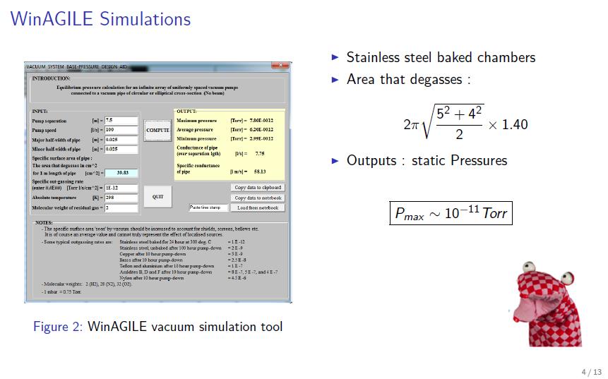
5 Primary tool AGILE: Multi-purpose Freeware Lattice construction Linear Optics matching Chromaticity correction Radiation loss calculations Vacuum calculations Etc.


6 Group structure Experts: Phillip Bryant Riccardo Bartolini Lattice 1 & 2 S. Vallières Project leader J. Kallestrup RF systems R.C. Prajapati Chromaticity, tune control & Resonance exitation T. Pugnat Closed orbit control C. Agazzi Effects of space charge Vacuum systems H. Guérin Insertion Devices & synchrotron radiation A.Gilardi D.M. Garcia


7 Group structure Experts: Phillip Bryant Riccardo Bartolini Lattice 1 & 2 S. Vallières Project leader J. Kallestrup RF systems R.C. Prajapati Chromaticity, tune control & Resonance exitation T. Pugnat Closed orbit control C. Agazzi Effects of space charge Vacuum systems H. Guérin Insertion Devices & synchrotron radiation A.Gilardi D.M. Garcia
8 Lattice Group
9 Mandates to Fulfill Lattice 1 : Try to improve the basic cell design. Define apertures. Get radiation parameters. Lattice 2 : Create a dispersion-free 1:1 module to split the ring in 2 superperiods. Integrate the injection and extraction into the previous module.

10 Basic Ring ε x = 3.2π nm 8 quadrupoles per cell + 2 dipoles ($$)

11 Option 1: DBA with many FODOs ε x = 1.3π nm 12 quadrupoles per cell + 2 dipoles ($$$)

12 Option 2: TBA ε x = 0.8π nm 12 quadrupoles per cell + 3 dipoles ($$$$)

13 Option 3: low cost DBA ε x = 2.8π nm 5 quadrupoles per cell + 2 dipoles ($)


14 MODULE 1:1 β in x = β out x β in y = β out y α in x = α out x α in x = α out x μ out x = μ out y = 2π As expected
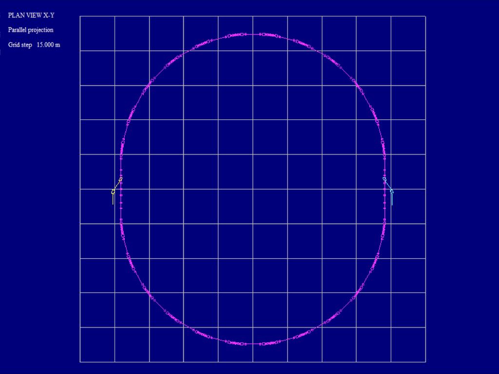
15 Extraction Injection

16 Twiss functions of the full ring with a low cost DBA
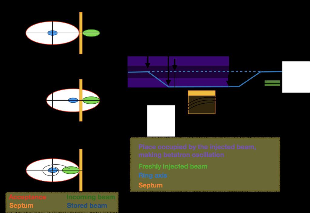
17 Injection/Extraction Scheme
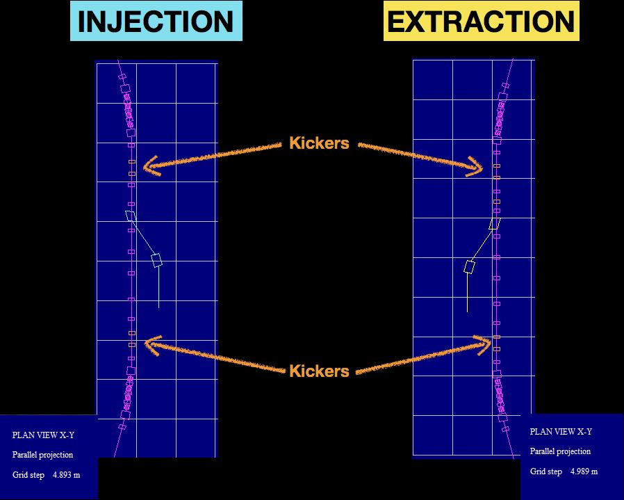
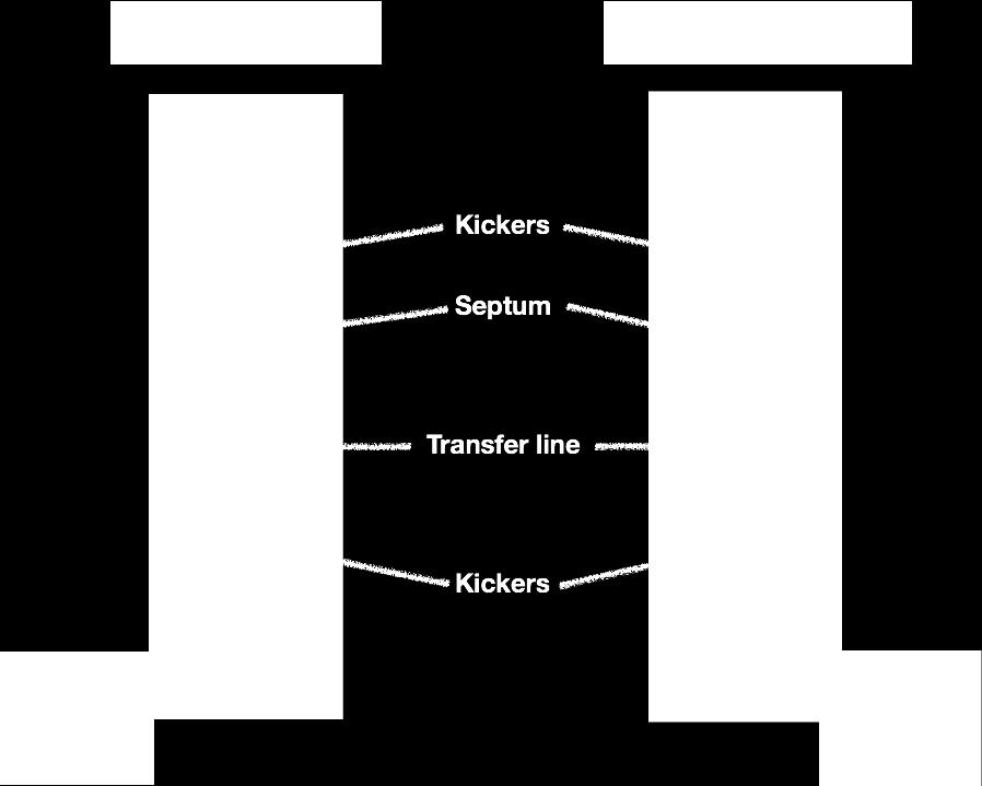
18

19 Injection with Orbit Bump Septum Kicker s

20
21 Tune and Chromaticity control By T. PUGNAT, V. CILENTO, E. FOL, D. VENTURA
22 Tune control Why? Prevent the machine to reach unstable region! 3 methods to correct the tune: Using main quad Two serie families of smaller quads distributed around the ring Adding backleg windings to the main quadrupole p.51-52
23 Tune control: using Quadrupole Qx = Qy= 6.77

24 Tune control: using Quadrupole Qx = Qy=

25 Tune control: Phase shifter Length*Scale Strength/Scale²

26 Tune control: Phase shifter x : 2 -> y :

27 Tune control: Phase shifter x : 2 y : -> + 0.2
28 Chromaticity control Achromaticity Q x = Q y = 0 Relation between chromaticity, stength of the quadrupole and strength of the Sextupole: Q x = k q x L q K s x D x L s Q y = k q y L q K s y D x L s x / y >> 1 or x / y >> 1 x D x >> 0 p.51-52
29 Chromaticity control
30 Chromaticity control Q x = & Q y = Sextupole OFF

31 Chromaticity control Q x = Q y = 0 XD: k2 = m-3 XF: k2 = m-3 Sextupole ON

32 Chromaticity control: W-vector Global chromaticity provide beam stability and control of the working line Local chromaticity prevent error from propagating from one cell to an other and necessary for undulator p.75-78

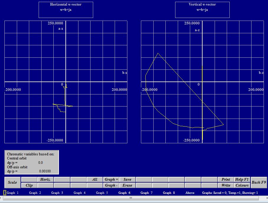
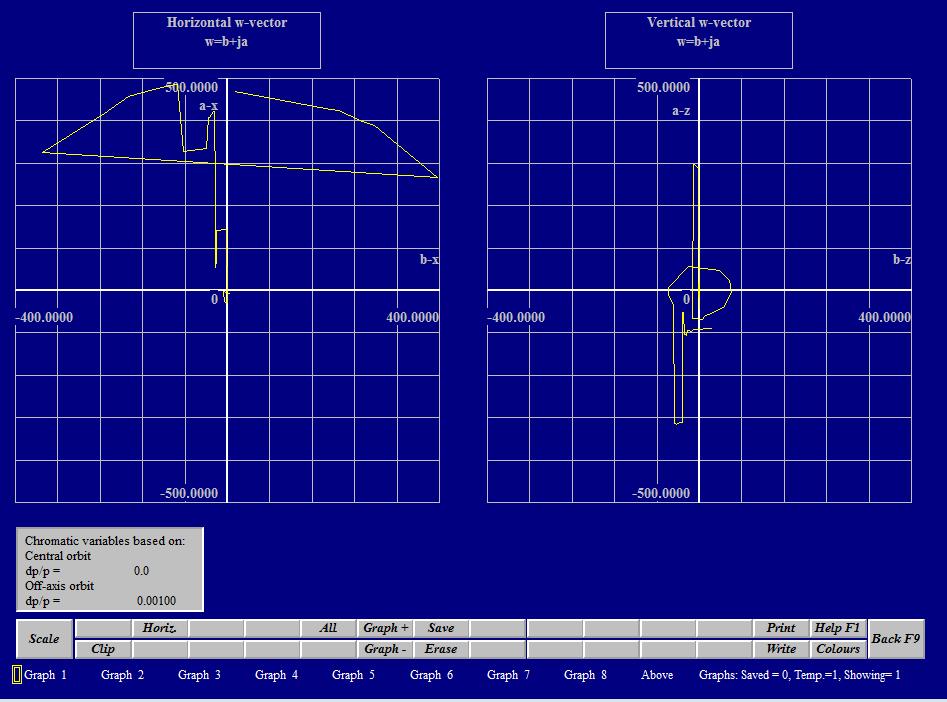
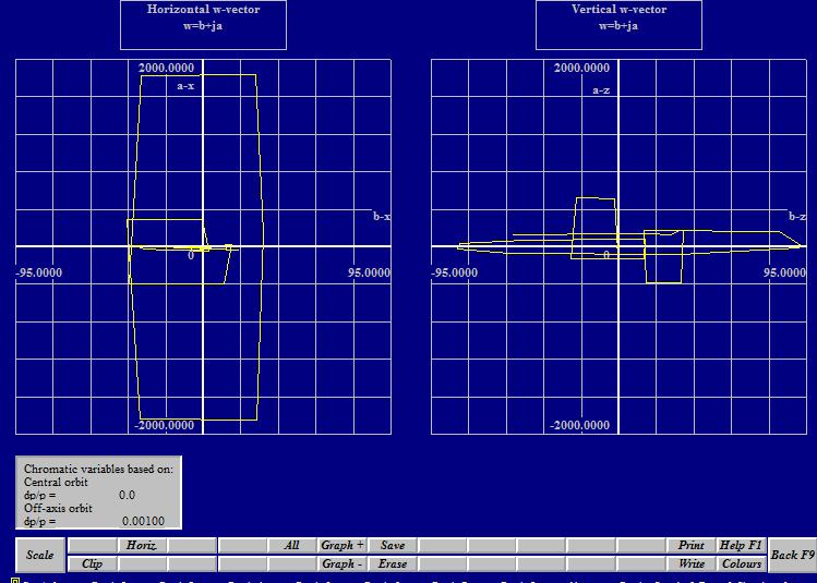
33 Chromaticity control: W-vector


34 Chromaticity control: try Sextupole in different localization Sextupole of the same family with a phase advance of pi Possible solution: Increase slowly the strength of the sextupole after injection
35 Dynamic aperture Lyapunov exponant Quantity that characterizes the rate of separation of infinitesimally close trajectories. Multi-turn Tracking Proposed scaling law for intensity evolution in hadron storage rings based on dynamic aperture variation with time, M. Giovannozzi
36 Closed Orbit Prognosis & Correction Costanza, Antonio, Alan
37 Prognosis: Statistic for Closed Orbit HOW IT WORKS? These prognosis are made by generating large numbers of virtual machines with estimated errors and calculating the statistics of the raw closed orbits and the corrected closed orbits. The error is interpreted as dipole kicks. For example, a longitudinal position error of 1 mm for a dipole is represented as a missing-field kick at one end of the dipole and an additionalfield kick at the other end. This is done randomly with a uniform or Gaussian distribution. WHAT WE HAVE DONE To perform our prognosis we set a shift error in the position of the quadrupoles of 0.001m, first in the horizontal and then in the vertical plane. We used a Gaussian distribution of the kicks. We run a simulation of 1000 machines and we studied separately the correction of a single closed orbit in the two planes.


38 MAX.HORIZONTAL PEAK-PEAK: m AVERAGE HORIZONTAL PEAK- PEAK: m MAX. VERTICAL PEAK-PEAK: m AVERAGE VERTICAL PEAK- PEAK: m
 BPMs, 158(x2) vertical (VCORR) and horizontal (HCORR)")

39 The closed orbit was measured and corrected by: 158(x2) vertical (VPU) and horizontal (HPU) BPMs, 158(x2) vertical (VCORR) and horizontal (HCORR) correctors We placed BPMs and Correctors next to the Dipoles and close to Quadrupoles and Sextupoles, which represent the main sources of misalignment.

40 Correction Before studying the Statistic for Corrected Closed Orbit, we investigated the behaviour of a single closed orbit and its correction.
41 We corrected the previous closed orbit using all the available correctors (158 in the horizontal plane). Once fixed the number of correctors and the plane to be corrected, the routine computes a selection of the best correctors out of those available. The Computation Method used to select the best correctors is a Least Square Fit (also an SVD method is available)
42 ZOOM of the corrected Closed Orbit: Starting from a closed orbit with maximum amplitude of around 0.45 m we reached a final amplitude of 1.5 mm in the horizontal plane!
43 Vertical CO after the correction Vertical CO before the correction

44 ZOOM of the corrected Closed Orbit: Starting from a closed orbit with maximum amplitude of around 0.15 m we reached a final amplitude of 0.7 mm in the vertical plane!
45 Statistic for Corrected Closed Orbit Although there may be a large number of correctors available, it is usually advantageous to check if a small number of correctors will correct the orbit. This increases reliability because : - there are fewer power converters working - it increases the currents delivered by those that are working, helping to prevent instabilities. The maximum number of calculations for a statistical analysis is 1000, but it is recommended that a test run is made with around 100 calculations. What we have done to compute the Statistic for Corrected Closed Orbit in a timesaving way was to run a test with 100 machines, limiting the number of the corrector to 20.
46 MAX.HORIZONTAL PEAK- PEAK: m AVERAGE HORIZONTAL PEAK- PEAK: m MAX.HORIZONTAL PEAK-PEAK: 0,197763m AVERAGE HORIZONTAL PEAK- PEAK: m
47
48 Space charge study for JUICE

49 Tune diagram
50 Computation of Space Charge in WinAgile Free space wavelength = 0.6 m Bunch length = m Bunching Factor = 0.6 / = 5

51 Incoherent Space Charge WinAgile - No change Theoretical dqh = e-8 dqv = e-8
52 Incoherent Space Charge WinAgile - No change Theoretical dqh = e-8 dqv = e-8

53 Coherent Space charge WinAgile Tune H = dqh = *5 = e-3 Tune V = dqv = *5 = e-2 Theoretical dqh = = e-4 dqv = = e-4

54 Change of Vacuum chamber aperture Electrostatic Images
55 Change of magnets gap Magnetic images
56 Lower Energy Energy equal to 2 GeV Incoherent: No change Coherent: Tune H = dqh = * 5 = e-3 Tune V = dqv = * 5 = e-3
57
58
59
60
61
62
63
64
65
66 SR workshop (R. Bartolini) The goal of the workshop is to design synchrotron light source based on a DBA lattice. The beam energy is 3 GeV. From the initial DBA cell from P. J. Bryant compute critical frequency of bending, energy loss, total power radiated Install IDs to reach 5 kev compute tuning range, bandwidth, energy loss per turn, total power emitted by the IDs, brilliance, tuning curves compute the RF power needed for 300 ma assume 8 DBA cells with 3.2 m straight sections complete matching (achieve betay = 2m in SS, check tunes) play with optics to reduce the emittance (break the achromatic condition) Investigate other cells (TBA)
67 Radiation from bendings Bending field 1.4 T - bending radius 7.1 m energy loss per turn: Bending magnets 4 E GeV U 0,bend = ρ[m] Critical energy ε c = E[GeV] ρ[m] = 8.4 [kev] 1.0 MeV Power emitted as Synchrotron Radiation: P kw = U 0 kev I beam = kev 0.3 A = 300 [kw] Assuming 50% efficiency the RF power must be: P kw = 600 [kw]


68 With this equipment, we choose to work: λ = 25mm Br = 1.0 T Energy required
 K = 9.")
![496 n E GeV 2 λ u m ε n [ev] 1 The value obtained is K](/docs-images/94/119290383/images/69-2.jpg "= 1.56 n = 5 K= 1.")
69 From the following formula is possible to obtain K (the undulator parameter) K = n E GeV 2 λ u m ε n [ev] 1 The value obtained is K = 1.56 n = 5 K= 1.03 n = 3 Such photon energy can be radiated only in harmonics
70 Mind that different parameterisations can be found NOTE: First formula use lengths in mm n B_0 Gap B_r T 11.2 mm T 7.9 mm 1
71 Tuning range: K min ~ 0.5 K max (4 mm) = 2.54 Tuning range: Third harmonics ~ kev Fifth harmonics ~ kev Energy loss per electron in one wiggler in 1 turn: Energy loss per turn (K=1.03) = 83 kev Energy loss per turn (K=1.56) = 190 kev
72 Why not adding 22 WIGGLERS? Total energy loss: Bending magnets + all wigglers K = 1.03 U 0,wigglers = N wig U 0,1 wiggler = [kev ] = 1.83 [MeV] U 0,total = 1.0 MeV MeV = [MeV] K = 1.56 U 0,wigglers = N wig U 0,1 wiggler = [kev ] = 4.18 [MeV] U 0,total = 1.0 MeV MeV = [MeV] Power emitted as Synchrotron Radiation: P kw = U 0 kev I beam = kev 0.3 A = 849 [kw] P kw = U 0 kev I beam = kev 0.3 A = 1550 [kw] Compared to 300 kw for dipoles only we obtained a factor between 3 and 5
73 RF Design workshop Goal: Design RF System Input Parameters: To operate at 500 MHz frequency (f rf ) To accelerate from 2 GeV to 3 GeV Compensate Energy Losses (Synchrotron Radiation, Wiggler) Pill-Box RF Cavity Define RF System and RF Programme Calculate Voltage (V rf ), RF- Power Presented by RF-Team Francesco GIORDANO Markus JAEGER Mohamed KARIMELDIN Rakesh Chandra PRAJAPATI

74 Pill-Box RF-Cavity for acceleration
75 RF Parameters (Frequency, Voltage, Power) f rf = 500 MHz Circumference of Main Ring (C ring ) = m f rev = c/c ring = 3x10 8 / = khz Harmonic Number (h) = f rf /f rev 677 Pill-Box RF Cavity: Radius of Cavity = λ = x 60 = 23 cm Length of Gap inside the Cavity = 10 cm
76 Accelerating Voltage (RF-Voltage) Partical Energy (E) = 3 GeV Bending Radius (ρ) = 7 m Synchrotron Radiation (SR) Loss per Turn (ΔE) = 1 MeV Hence, to compensate SR Energy Loss, accelerating voltage of 1 MV is required. For sufficient beam life-time, Over Voltage Factor of at least 2 is required. Therefore, we provide 2.5 MV accelerating voltage in the Main Ring through 4 RF-Cavities. (N cavity = 4)
77 RF Power requirement 2.5 MV voltage in the Main Ring through 4 RF-Cavities. (N cavity = 4) Therefore, each RF-cavity operates at 2.5 MV/4 = 625 kv 1. Power Required To Generate Accelerating Voltage RF Cavity Power (P acc ) = V 2 /R sh = (625 kv) 2 /3.5 MΩ = 112 kw (each RF cavitiy) 2. Power Required To Compensate for SR Loss SR Loss Power (P SRL ) = Stored Current X Voltage for SR Loss Compensation = 300 ma X 1MV = 300 kw 3. Power Required To Compensate Wiggler Loss Wiggler Loss Power (Pwiggler) = 1550 kw Total Power Required (P total ) = (N x P acc ) + P SRL + Pwiggler = 4x112 kw kw kw = 748 kw kw = 2.3 MW

78 RF Voltage per Cavity vs. SynchtRon Loss E inj. = 2GeV E top = 3GeV E inj < E < E top V RF = 2 π ρ R ሶ B + ΔE N sin(φ s )

79 Gamma vs. synchtron loss γ = E E 0 2GeV<E<3GeV Synchtron Radiation Loss Per Turn is 1 MeV.

80 Synchtron radiation loss compensation 4 RF cavities are compensating the energy loss of the beam due to Synchtron Radiation.
, Q, R s Quality factor Q = stored field energy / ohmic loss per")
 2 / ohmic loss R s ( E0LT) P diss 2 skin")
81 RF-Cavity design (from pill-box to Elliptical/spherical) Improving the 3 Figures of Merit: ω rf (fixed), Q, R s Quality factor Q = stored field energy / ohmic loss per RF oscillation U RL 2V Q P ( R L) A volume surface area diss skin skin Shunt Impedance R s = (voltage gain per particle) 2 / ohmic loss R s ( E0LT) P diss 2 skin 1 cavitysize
 2.5 MV 4 0.")
82 RF System from diamond Light source (Our Design Parameters) 2.5 MV MV 500 MHz 2.5
83 RF Engineering design consideration Tuning Mechanism: Frequency tuning of RF cavity should be non-contacting plunger, normal plunger movement can cause beam movement of the order 20 μm. Cooling System: Power Dissipate per Cavity = 748 kw / 4 = 187 kw. Thus, we need water-cooling mechanism. Specific heat capacity of water is C P = J/(kg.K), thus, 400 liters/min cooling system will have 4 C difference in inlet and outlet. Proper cooling system should be used to keep uniform temperature gradient, otherwise, distortion in cavity geometry can result, and consequently change the frequency. c Ohmic Heating/ Power dissipation: 2 c P diss skin skin

84 Block-diagram of accelerator rf system
85 Thank you!
Lattice Design and Performance for PEP-X Light Source
 Lattice Design and Performance for PEP-X Light Source Yuri Nosochkov SLAC National Accelerator Laboratory With contributions by M-H. Wang, Y. Cai, X. Huang, K. Bane 48th ICFA Advanced Beam Dynamics Workshop
Lattice Design for the Taiwan Photon Source (TPS) at NSRRC
 at NSRRC") Lattice Design for the Taiwan Photon Source (TPS) at NSRRC Chin-Cheng Kuo On behalf of the TPS Lattice Design Team Ambient Ground Motion and Civil Engineering for Low Emittance Electron Storage Ring Workshop
Lattice Design for the Taiwan Photon Source (TPS) at NSRRC Chin-Cheng Kuo On behalf of the TPS Lattice Design Team Ambient Ground Motion and Civil Engineering for Low Emittance Electron Storage Ring Workshop
First propositions of a lattice for the future upgrade of SOLEIL. A. Nadji On behalf of the Accelerators and Engineering Division
 First propositions of a lattice for the future upgrade of SOLEIL A. Nadji On behalf of the Accelerators and Engineering Division 1 SOLEIL : A 3 rd generation synchrotron light source 29 beamlines operational
Accelerator Physics. Accelerator Development
 Accelerator Physics The Taiwan Light Source (TLS) is the first large accelerator project in Taiwan. The goal was to build a high performance accelerator which provides a powerful and versatile light source
3. Synchrotrons. Synchrotron Basics
 1 3. Synchrotrons Synchrotron Basics What you will learn about 2 Overview of a Synchrotron Source Losing & Replenishing Electrons Storage Ring and Magnetic Lattice Synchrotron Radiation Flux, Brilliance
SLS at the Paul Scherrer Institute (PSI), Villigen, Switzerland
, Villigen, Switzerland") SLS at the Paul Scherrer Institute (PSI), Villigen, Switzerland Michael Böge 1 SLS Team at PSI Michael Böge 2 Layout of the SLS Linac, Transferlines Booster Storage Ring (SR) Beamlines and Insertion Devices
SLS at the Paul Scherrer Institute (PSI), Villigen, Switzerland Michael Böge 1 SLS Team at PSI Michael Böge 2 Layout of the SLS Linac, Transferlines Booster Storage Ring (SR) Beamlines and Insertion Devices
Transverse dynamics Selected topics. Erik Adli, University of Oslo, August 2016, v2.21
 Transverse dynamics Selected topics Erik Adli, University of Oslo, August 2016, Erik.Adli@fys.uio.no, v2.21 Dispersion So far, we have studied particles with reference momentum p = p 0. A dipole field
ILC Damping Ring Alternative Lattice Design **
 ILC Damping Ring Alternative Lattice Design ** Yi-Peng Sun *,1,2, Jie Gao 1, Zhi-Yu Guo 2 1 Institute of High Energy Physics, CAS, Beijing 2 Key Laboratory of Heavy Ion Physics, Peking University, Beijing
Lattices for Light Sources
 Andreas Streun Swiss Light Source SLS, Paul Scherrer Institute, Villigen, Switzerland Contents: Global requirements: size, brightness, stability Lattice building blocks: magnets and other devices Emittance:
Conceptual design of an accumulator ring for the Diamond II upgrade
 Journal of Physics: Conference Series PAPER OPEN ACCESS Conceptual design of an accumulator ring for the Diamond II upgrade To cite this article: I P S Martin and R Bartolini 218 J. Phys.: Conf. Ser. 167
Longitudinal Top-up Injection for Small Aperture Storage Rings
 Longitudinal Top-up Injection for Small Aperture Storage Rings M. Aiba, M. Böge, Á. Saá Hernández, F. Marcellini and A. Streun Paul Scherrer Institut Introduction Lower and lower horizontal emittances
STATUS REPORT ON STORAGE RING REALIGNMENT AT SLRI
 STATUS REPORT ON STORAGE RING REALIGNMENT AT SLRI S. Srichan #, A. Kwankasem, S. Boonsuya, B. Boonwanna, V. Sooksrimuang, P. Klysubun Synchrotron Light Research Institute, 111 University Ave, Muang District,
COMBINER RING LATTICE
 CTFF3 TECHNICAL NOTE INFN - LNF, Accelerator Division Frascati, April 4, 21 Note: CTFF3-2 COMBINER RING LATTICE C. Biscari 1. Introduction The 3 rd CLIC test facility, CTF3, is foreseen to check the feasibility
ILC Damping Ring Alternative Lattice Design (Modified FODO)
") ILC Damping Ring Alternative Lattice Design (Modified FODO) Yi-Peng Sun 1,2, Jie Gao 1, Zhi-Yu Guo 2 Wei-Shi Wan 3 1 Institute of High Energy Physics, CAS, China 2 State Key Laboratory of Nuclear Physics
ILC Damping Ring Alternative Lattice Design (Modified FODO) Yi-Peng Sun 1,2, Jie Gao 1, Zhi-Yu Guo 2 Wei-Shi Wan 3 1 Institute of High Energy Physics, CAS, China 2 State Key Laboratory of Nuclear Physics
LIS section meeting. PS2 design status. Y. Papaphilippou. April 30 th, 2007
 LIS section meeting PS2 design status Y. Papaphilippou April 30 th, 2007 Upgrade of the injector chain (R. Garoby, PAF) Proton flux / Beam power 50 MeV 160 MeV Linac2 Linac4 1.4 GeV ~ 5 GeV PSB SPL RCPSB
LOW EMITTANCE MODEL FOR THE ANKA SYNCHROTRON RADIATION SOURCE
 Karlsruhe Institute of Technology (KIT, Karlsruhe, Germany) Budker Institute of Nuclear Physics (BINP, Novosibirsk, Russia) LOW EMITTANCE MODEL FOR THE ANKA SYNCHROTRON RADIATION SOURCE (A.Papash - on
FIRST OPERATION OF THE SWISS LIGHT SOURCE
 FIRST OPERATION OF THE SWISS LIGHT SOURCE M. Böge, PSI, Villigen, Switzerland Abstract The Swiss Light Source (SLS) at the Paul Scherrer Institute (PSI) is the most recent 3rd generation light source to
Proposal to convert TLS Booster for hadron accelerator
 Proposal to convert TLS Booster for hadron accelerator S.Y. Lee -- Department of Physics IU, Bloomington, IN -- NSRRC Basic design TLS is made of a 50 MeV electron linac, a booster from 50 MeV to 1.5 GeV,
The FAIR Accelerator Facility
 The FAIR Accelerator Facility SIS300 existing GSI proton linac SIS18 UNILAC SIS100 HESR pbar target SuperFRS goals: higher intensity (low charge states) higher energy (high charge states) production of
Insertion Devices Lecture 2 Wigglers and Undulators. Jim Clarke ASTeC Daresbury Laboratory
 Insertion Devices Lecture 2 Wigglers and Undulators Jim Clarke ASTeC Daresbury Laboratory Summary from Lecture #1 Synchrotron Radiation is emitted by accelerated charged particles The combination of Lorentz
HIRFL STATUS AND HIRFL-CSR PROJECT IN LANZHOU
 HIRFL STATUS AND HIRFL-CSR PROJECT IN LANZHOU J. W. Xia, Y. F. Wang, Y. N. Rao, Y. J. Yuan, M. T. Song, W. Z. Zhang, P. Yuan, W. Gu, X. T. Yang, X. D. Yang, S. L. Liu, H.W.Zhao, J.Y.Tang, W. L. Zhan, B.
Accelerator Design and Construction Progress of TPS Project
 Accelerator Design and Construction Progress of TPS Project Taiwan Light Source (TLS), a 120-m storage ring originally designed for 1.3 GeV, was commissioned and opened to users in 1993. The energy of
Beam Dynamics. D. Brandt, CERN. CAS Bruges June 2009 Beam Dynamics D. Brandt 1
 Beam Dynamics D. Brandt, CERN D. Brandt 1 Some generalities D. Brandt 2 Units: the electronvolt (ev) The electronvolt (ev)) is the energy gained by an electron travelling, in vacuum, between two points
III. CesrTA Configuration and Optics for Ultra-Low Emittance David Rice Cornell Laboratory for Accelerator-Based Sciences and Education
 III. CesrTA Configuration and Optics for Ultra-Low Emittance David Rice Cornell Laboratory for Accelerator-Based Sciences and Education Introduction Outline CESR Overview CESR Layout Injector Wigglers
Compressor Lattice Design for SPL Beam
 EUROPEAN ORGANIZATION FOR NUCLEAR RESEARCH CERN A&B DIVISION AB-Note-27-34 BI CERN-NUFACT-Note-153 Compressor Lattice Design for SPL Beam M. Aiba Abstract A compressor ring providing very short proton
On-axis injection into small dynamic aperture
 On-axis injection into small dynamic aperture L. Emery Accelerator Systems Division Argonne National Laboratory Future Light Source Workshop 2010 Tuesday March 2nd, 2010 On-Axis (Swap-Out) injection for
1.5-GeV FFAG Accelerator as Injector to the BNL-AGS
 1.5-GeV FFAG Accelerator as Injector to the BNL-AGS Alessandro G. Ruggiero M. Blaskiewicz,, T. Roser, D. Trbojevic,, N. Tsoupas,, W. Zhang Oral Contribution to EPAC 04. July 5-9, 5 2004 Present BNL - AGS
Abstract. 1. Introduction
 The New Upgrade of SESAME D.Einfeld1, R.H.Sarraf2, M.Attal3, H.Hashemi4, A.Elsisi5, A.Amro6, H.Hassanzadegan4, K.Tavakoli3, B.Kalantari7, S. Varnasery8, E. Al-Dmour8, D. Foudeh6, H.Tarawneh9, A.Aladwan7
Turn-by-Turn Beam Position Measurements at ANKA with LIBERA ELECTRON
 Turn-by-Turn Beam Position Measurements at ANKA with LIBERA ELECTRON E.Huttel, I.Birkel, A.S.Müller, P.Wesolowski About ANKA Test by Frequency Generator Experiences in the Booster Experiences in the Storage
Commissioning of PETRA III. Klaus Balewski on behalf of the PETRA III Team IPAC 2010, 25 May, 2010
 Commissioning of PETRA III Klaus Balewski on behalf of the PETRA III Team IPAC 2010, 25 May, 2010 PETRA III Parameters Circumference (m) Energy (GeV) ε x (nm rad) ε y (pm rad) Current (ma) # bunches Straight
Practical Lattice Design
 Practical Lattice Design Dario Pellegrini (CERN) dario.pellegrini@cern.ch USPAS January, 15-19, 2018 1/17 D. Pellegrini - Practical Lattice Design Lecture 5. Low Beta Insertions 2/17 D. Pellegrini - Practical
Experience on Coupling Correction in the ESRF electron storage ring
 Experience on Coupling Correction in the ESRF electron storage ring Laurent Farvacque & Andrea Franchi, on behalf of the Accelerator and Source Division Future Light Source workshop 2012 Jefferson Lab,
Compressor Ring. Contents Where do we go? Beam physics limitations Possible Compressor ring choices Conclusions. Valeri Lebedev.
 Compressor Ring Valeri Lebedev Fermilab Contents Where do we go? Beam physics limitations Possible Compressor ring choices Conclusions Muon Collider Workshop Newport News, VA Dec. 8-1, 8 Where do we go?
A Project to convert TLS Booster to hadron accelerator 1. Basic design. 2. The injection systems:
 A Project to convert TLS Booster to hadron accelerator 1. Basic design TLS is made of a 50 MeV electron linac, a booster from 50 MeV to 1.5 GeV, and a storage ring. The TLS storage ring is currently operating
Operational Experience with HERA
 PAC 07, Albuquerque, NM, June 27, 2007 Operational Experience with HERA Joachim Keil / DESY On behalf of the HERA team Contents Introduction HERA II Luminosity Production Experiences with HERA Persistent
ThomX Machine Advisory Committee. (LAL Orsay, March ) Ring Beam Dynamics
 Ring Beam Dynamics") ThomX Machine Advisory Committee (LAL Orsay, March 20-21 2017) Ring Beam Dynamics A. Loulergue, M. Biagini, C. Bruni, I. Chaikovska I. Debrot, N. Delerue, A. Gamelin, H. Guler, J. Zang Programme Investissements
ThomX Machine Advisory Committee (LAL Orsay, March 20-21 2017) Ring Beam Dynamics A. Loulergue, M. Biagini, C. Bruni, I. Chaikovska I. Debrot, N. Delerue, A. Gamelin, H. Guler, J. Zang Programme Investissements
Putting it all together
 Putting it all together Werner Herr, CERN (Version n.n) http://cern.ch/werner.herr/cas24/lectures/praha review.pdf 01 0 1 00 11 00 11 00 11 000 111 01 0 1 00 11 00 11 00 11 000 111 01 0 1 00 11 00 11 00
The optimization for the conceptual design of a 300 MeV proton synchrotron *
 The optimization for the conceptual design of a 300 MeV proton synchrotron * Yu-Wen An ( 安宇文 ) 1,2), Hong-Fei Ji ( 纪红飞 ) 1,2), Sheng Wang ( 王生 ) 1,2), Liang-Sheng Huang ( 黄良生 ) 1,2;1) 1 Institute of High
3.2.2 Magnets. The properties of the quadrupoles, sextupoles and correctors are listed in tables t322_b,_c and _d.
 3.2.2 Magnets The characteristics for the two types of combined function magnets,bd and BF, are listed in table t322_a. Their cross-sections are shown, together with the vacuum chamber, in Figure f322_a.
Emittance Growth and Tune Spectra at PETRA III
 Emittance Growth and Tune Spectra at PETRA III Presentation at the ECLOUD 2010 workshop Rainer Wanzenberg ECLOUD 2010 October 8-12, 2010 Statler Hotel, Cornell University Ithaca, New York USA PETRA III
PBL SCENARIO ON ACCELERATORS: SUMMARY
 PBL SCENARIO ON ACCELERATORS: SUMMARY Elias Métral Elias.Metral@cern.ch Tel.: 72560 or 164809 CERN accelerators and CERN Control Centre Machine luminosity Transverse beam dynamics + space charge Longitudinal
Low energy electron storage ring with tunable compaction factor
 REVIEW OF SCIENTIFIC INSTRUMENTS 78, 075107 2007 Low energy electron storage ring with tunable compaction factor S. Y. Lee, J. Kolski, Z. Liu, X. Pang, C. Park, W. Tam, and F. Wang Department of Physics,
First Collective Effects Measurements in NSLS-II A. Blednykh Accelerator Physicist, BNL/NSLS-II Sep , 2014
 First Collective Effects Measurements in NSLS-II A. Blednykh Accelerator Physicist, BNL/NSLS-II Sep. 17-19, 2014 (LOWεRING 2014) 1 BROOKHAVEN SCIENCE ASSOCIATES Outline Phase 1 (25mA / PETRA-III) and Phase
6 Bunch Compressor and Transfer to Main Linac
 II-159 6 Bunch Compressor and Transfer to Main Linac 6.1 Introduction The equilibrium bunch length in the damping ring (DR) is 6 mm, too long by an order of magnitude for optimum collider performance (σ
Status of the ESR And Future Options
 Status of the ESR And Future Options M. Steck for the Storage Ring Division (C. Dimopoulou, A. Dolinskii, S. Litvinov, F. Nolden, P. Petri, U. Popp, I. Schurig) Outline 1) New Old ESR 2) Slow (Resonant)
Bernhard Holzer, CERN-LHC
 Bernhard Holzer, CERN-LHC * Bernhard Holzer, CERN CAS Prague 2014 x Liouville: in reasonable storage rings area in phase space is constant. A = π*ε=const x ε beam emittance = woozilycity of the particle
Iranian Light Source Facility (ILSF) Project
 Project") Iranian Light Source Facility (ILSF) Project Hossein Ghasem On behalf of ILSF technical staff School of Particles and Accelerators, IPM 1390 29 28 1 Iranian users requirements Source Energy range Photon
Iranian Light Source Facility (ILSF) Project Hossein Ghasem On behalf of ILSF technical staff School of Particles and Accelerators, IPM 1390 29 28 1 Iranian users requirements Source Energy range Photon
COMMISSIONING OF NSLS-II*
 COMMISSIONING OF NSLS-II* F. Willeke, BNL, Upton, NY 11973, USA Figure 1: Aerial view of NSLS-II. Abstract NSLS-II, the new 3rd generation light source at BNL was designed for a brightness of 10 22 photons
Low alpha mode for SPEAR3 and a potential THz beamline
 Low alpha mode for SPEAR3 and a potential THz beamline X. Huang For the SSRL Accelerator Team 3/4/00 Future Light Source Workshop 00 --- X. Huang Outline The low-alpha mode for SPEAR3 Potential for a THz
RADIATION SOURCES AT SIBERIA-2 STORAGE RING
 RADIATION SOURCES AT SIBERIA-2 STORAGE RING V.N. Korchuganov, N.Yu. Svechnikov, N.V. Smolyakov, S.I. Tomin RRC «Kurchatov Institute», Moscow, Russia Kurchatov Center Synchrotron Radiation undulator undulator
The TESLA Dogbone Damping Ring
 The TESLA Dogbone Damping Ring Winfried Decking for the TESLA Collaboration April 6 th 2004 Outline The Dogbone Issues: Kicker Design Dynamic Aperture Emittance Dilution due to Stray-Fields Collective
Phase Space Study of the Synchrotron Oscillation and Radiation Damping of the Longitudinal and Transverse Oscillations
 ScienceAsia 28 (2002 : 393-400 Phase Space Study of the Synchrotron Oscillation and Radiation Damping of the Longitudinal and Transverse Oscillations Balabhadrapatruni Harita*, Masumi Sugawara, Takehiko
Small Synchrotrons. Michael Benedikt. CERN, AB-Department. CAS, Zeegse, 30/05/05 Small Synchrotrons M. Benedikt 1
 Small Synchrotrons Michael Benedikt CERN, AB-Department CAS, Zeegse, 30/05/05 Small Synchrotrons M. Benedikt 1 Contents Introduction Synchrotron linac - cyclotron Main elements of the synchrotron Accelerator
Accelerators. There are some accelerators around the world Nearly all are for industrial (20 000) or clinical use (10 000)
 or clinical use (10 000)") Accelerators There are some 30 000 accelerators around the world Nearly all are for industrial (20 000) or clinical use (10 000) Scientific research community (~ 100) Synchrotron light sources Ion beam
Accelerators There are some 30 000 accelerators around the world Nearly all are for industrial (20 000) or clinical use (10 000) Scientific research community (~ 100) Synchrotron light sources Ion beam
Beam Optics design for CEPC collider ring
 Beam Optics design for CEPC collider ring, Yuan Zhang, Yuanyuan Wei, Sha Bai, Dou Wang, Huiping Geng, Chenghui Yu, Jie Gao IHEP, Beijing 1st workshop on applications of high energy Circular Electron-Positron
Research with Synchrotron Radiation. Part I
 Research with Synchrotron Radiation Part I Ralf Röhlsberger Generation and properties of synchrotron radiation Radiation sources at DESY Synchrotron Radiation Sources at DESY DORIS III 38 beamlines XFEL
NSRRC Current Status and the TPS Project
 NSRRC Current Status and the TPS Project Chien-Te Chen July 21, 2005 1-1 Milestones 1981 Dec. Feasibility study began 1983 Jul. SRRC Project approved by the government 1986 Mar. Preparatory Office of SRRC
Collider Rings and IR Design for MEIC
 Collider Rings and IR Design for MEIC Alex Bogacz for MEIC Collaboration Center for Advanced Studies of Accelerators EIC Collaboration Meeting The Catholic University of America Washington, DC, July 29-31,
Lattices and Emittance
 Lattices and Emittance Introduction Design phases Interfaces Space Lattice building blocks local vs. global Approximations Fields and Magnets Beam dynamics pocket tools Transfer matrices and betafunctions
{ } Double Bend Achromat Arc Optics for 12 GeV CEBAF. Alex Bogacz. Abstract. 1. Dispersion s Emittance H. H γ JLAB-TN
 JLAB-TN-7-1 Double Bend Achromat Arc Optics for 12 GeV CEBAF Abstract Alex Bogacz Alternative beam optics is proposed for the higher arcs to limit emittance dilution due to quantum excitations. The new
Diagnostics at the MAX IV 3 GeV storage ring during commissioning. PPT-mall 2. Åke Andersson On behalf of the MAX IV team
 Diagnostics at the MAX IV 3 GeV storage ring during commissioning PPT-mall 2 Åke Andersson On behalf of the MAX IV team IBIC Med 2016, linje Barcelona Outline MAX IV facility overview Linac injector mode
CEPC Linac Injector. HEP Jan, Cai Meng, Guoxi Pei, Jingru Zhang, Xiaoping Li, Dou Wang, Shilun Pei, Jie Gao, Yunlong Chi
 HKUST Jockey Club Institute for Advanced Study CEPC Linac Injector HEP218 22 Jan, 218 Cai Meng, Guoxi Pei, Jingru Zhang, Xiaoping Li, Dou Wang, Shilun Pei, Jie Gao, Yunlong Chi Institute of High Energy
Accelerator Physics. Tip World Scientific NEW JERSEY LONDON SINGAPORE BEIJING SHANGHAI HONG KONG TAIPEI BANGALORE. Second Edition. S. Y.
 Accelerator Physics Second Edition S. Y. Lee Department of Physics, Indiana University Tip World Scientific NEW JERSEY LONDON SINGAPORE BEIJING SHANGHAI HONG KONG TAIPEI BANGALORE Contents Preface Preface
Effect of Insertion Devices. Effect of IDs on beam dynamics
 Effect of Insertion Devices The IDs are normally made of dipole magnets ith alternating dipole fields so that the orbit outside the device is un-altered. A simple planer undulator ith vertical sinusoidal
Low Emittance Storage Ring for Light Source. Sukho Kongtawong PHY 554 Fall 2016
 Low Emittance Storage Ring for Light Source Sukho Kongtawong PHY 554 Fall 2016 Content Brightness and emittance Radiative effect and emittance Theory Theoretical Minimum Emittance (TME) cell Double-bend
JSPS Asien Science Seminar Synchrotron Radiation Science
 SESAME Synchrotron Light for Experimental Science and Applications in the Middle East JSPS Asien Science Seminar Synchrotron Radiation Science Dieter Einfeld Amman, October 2002 Introduction Based on the
Canadian Light Source: Overview
 Canadian Light Source: Overview 2010 April Outline CLS project history Accelerator design Accelerator performance and development Beamlines accelerator-related activity Future plans The Case for CLS 10000
Accelerator Physics Final Exam pts.
 Accelerator Physics Final Exam - 170 pts. S. M. Lund and Y. Hao Graders: C. Richard and C. Y. Wong June 14, 2018 Problem 1 P052 Emittance Evolution 40 pts. a) 5 pts: Consider a coasting beam composed of
Application of cooling methods at NICA project. G.Trubnikov JINR, Dubna
 Application of cooling methods at NICA project G.Trubnikov JINR, Dubna Outline 1. NICA scheme, modes of operation, working cycles;. Booster scheme, parameters, beam requirements; 3. Status of the electron
Lattice design and dynamic aperture optimization for CEPC main ring
 Lattice design and dynamic aperture optimization for CEPC main ring Yiwei Wang, Feng Su, Sha Bai, Yuan Zhang, Dou Wang, Huiping Geng, Chenghui Yu, Jie Gao HKUST IAS conference, 23-26 Jan 2017 Outline Fully
S. Guiducci. Table 1 PADME beam from Linac. Energy (MeV) 550. Number of positrons per pulse Pulse length (ns)
 550. Number of positrons per pulse Pulse length (ns)") K K DA ΦNE TECHNICAL NOTE INFN - LNF, Accelerator Division Frascati, 11/01/2017 Note: G-73 PRELIMINARY CONSIDERATIONS ON THE USE OF DAΦNE POSITRON RING AS A PULSE STRETCHER FOR THE DAΦNE LINAC S. Guiducci
K K DA ΦNE TECHNICAL NOTE INFN - LNF, Accelerator Division Frascati, 11/01/2017 Note: G-73 PRELIMINARY CONSIDERATIONS ON THE USE OF DAΦNE POSITRON RING AS A PULSE STRETCHER FOR THE DAΦNE LINAC S. Guiducci
Choosing the Baseline Lattice for the Engineering Design Phase
 Third ILC Damping Rings R&D Mini-Workshop KEK, Tsukuba, Japan 18-20 December 2007 Choosing the Baseline Lattice for the Engineering Design Phase Andy Wolski University of Liverpool and the Cockcroft Institute
RF systems for the MAX IV rings
 RF systems for the MAX IV rings On behalf of the MAX-lab RF team Outline MAX IV overview Ring RF overview Main cavity design Higher harmonic cavity design MAX IV overview; site Start 3.5 GeV Linac Short
D. Brandt, CERN. CAS Frascati 2008 Accelerators for Newcomers D. Brandt 1
 Accelerators for Newcomers D. Brandt, CERN D. Brandt 1 Why this Introduction? During this school, you will learn about beam dynamics in a rigorous way but some of you are completely new to the field of
Minimum emittance superbend lattices?
 SLS-TME-TA-2006-0297 3rd January 2007 Minimum emittance superbend lattices? Andreas Streun Paul Scherrer Institut, CH-5232 Villigen PSI, Switzerland Andreas Streun, PSI, Dec.2004 Minimum emittance superbend
Introduction to Collider Physics
 Introduction to Collider Physics William Barletta United States Particle Accelerator School Dept. of Physics, MIT The Very Big Picture Accelerators Figure of Merit 1: Accelerator energy ==> energy frontier
The 2015 erhic Ring-Ring Design. Christoph Montag Collider-Accelerator Department Brookhaven National Laboratory
 The 2015 erhic Ring-Ring Design Christoph Montag Collider-Accelerator Department Brookhaven National Laboratory The Relativistic Heavy Ion Collider RHIC Two superconducting storage rings 3833.845 m circumference
Longitudinal Dynamics
 Longitudinal Dynamics F = e (E + v x B) CAS Bruges 16-25 June 2009 Beam Dynamics D. Brandt 1 Acceleration The accelerator has to provide kinetic energy to the charged particles, i.e. increase the momentum
Boster Synchrotron COMMISSIONING RESULTS LINAC. Storage Ring. Proceedings of IPAC2011, San Sebastián, Spain
 Proceedings of IPAC211, San Sebastián, Spain MOXAA1 ALBA SYNCHROTRON LIGHT SOURCE COMMISSIONING D. Einfeld, on behalf of the CELLS - Commissioning Team; CELLS-ALBA, E-829 Cerdanyola del Vallés, Spain,
Overview of Acceleration
 Overview of Acceleration R B Palmer, Scott Berg, Steve Kahn (presented by Steve Kahn) Nufact-04 RF Frequency Acc types and System Studies Linacs RLA s FFAG s Injection/Extraction US Study 2a acceleration
Coherent Synchrotron Radiation and Short Bunches in Electron Storage Rings. G. Wüstefeld, BESSY, Berlin (Germany)
") Coherent Synchrotron Radiation and Short Bunches in Electron Storage Rings G. Wüstefeld, BESSY, Berlin (Germany) Content content 1. Introduction 2. Low alpha optics for short bunches 3. Coherent radiation
Coherent Synchrotron Radiation and Short Bunches in Electron Storage Rings G. Wüstefeld, BESSY, Berlin (Germany) Content content 1. Introduction 2. Low alpha optics for short bunches 3. Coherent radiation
Introduction to Accelerators
 Introduction to Accelerators D. Brandt, CERN CAS Platja d Aro 2006 Introduction to Accelerators D. Brandt 1 Why an Introduction? The time where each accelerator sector was working alone in its corner is
High performance computing simulations. for multi-particle effects in the synchrotons
 High performance computing simulations for multi-particle effects in the synchrotons Content What is the HSC section doing? Physics basics PyHEADTAIL software Simulations of the PS Simulations of instabilities
3.2 The MAX IV 3 GeV Storage Ring
 25 38. S. Liuzzo et al. Test of Low emittance tuning at Diamond, Proceedings of the IPAC11, 2031, (2011). 39. L. Nadolski, Methods and tools to simulate and analyse nonlinear beam dynamics in electron
Ultra-Low Emittance Storage Ring. David L. Rubin December 22, 2011
 Ultra-Low Emittance Storage Ring David L. Rubin December 22, 2011 December 22, 2011 D. L. Rubin 2 Much of our research is focused on the production and physics of ultra-low emittance beams. Emittance is
Summary Report: Working Group 2 Storage Ring Sources Future Light Source Workshop SLAC, March 1-5, S. Krinsky and R. Hettel
 Summary Report: Working Group 2 Storage Ring Sources Future Light Source Workshop SLAC, March 1-5, 2010 S. Krinsky and R. Hettel Sessions 1. Low Emittance Ring Design --Y. Cai 2. Novel Concepts --D. Robin
ELECTRON DYNAMICS WITH SYNCHROTRON RADIATION
 ELECTRON DYNAMICS WITH SYNCHROTRON RADIATION Lenny Rivkin Ecole Polythechnique Federale de Lausanne (EPFL) and Paul Scherrer Institute (PSI), Switzerland CERN Accelerator School: Introduction to Accelerator
Engines of Discovery
 Engines of Discovery R.S. Orr Department of Physics University of Toronto Berkley 1930 1 MeV Geneva 20089 14 TeV Birth of Particle Physics and Accelerators 1909 Geiger/Marsden MeV a backscattering - Manchester
Terahertz Coherent Synchrotron Radiation at DAΦNE
 K K DAΦNE TECHNICAL NOTE INFN - LNF, Accelerator Division Frascati, July 28, 2004 Note: G-61 Terahertz Coherent Synchrotron Radiation at DAΦNE C. Biscari 1, J. M. Byrd 2, M. Castellano 1, M. Cestelli Guidi
Light Source I. Takashi TANAKA (RIKEN SPring-8 Center) Cheiron 2012: Light Source I
 Cheiron 2012: Light Source I") Light Source I Takashi TANAKA (RIKEN SPring-8 Center) Light Source I Light Source II CONTENTS Introduction Fundamentals of Light and SR Overview of SR Light Source Characteristics of SR (1) Characteristics
Light Source I Takashi TANAKA (RIKEN SPring-8 Center) Light Source I Light Source II CONTENTS Introduction Fundamentals of Light and SR Overview of SR Light Source Characteristics of SR (1) Characteristics
MAX-lab. MAX IV Lattice Design: Multibend Achromats for Ultralow Emittance. Simon C. Leemann
 Workshop on Low Emittance Rings 2010 CERN Jan 12 15, 2010 MAX-lab MAX IV Lattice Design: Multibend Achromats for Ultralow Emittance Simon C. Leemann simon.leemann@maxlab.lu.se Brief Overview of the MAX
$)ODW%HDP(OHFWURQ6RXUFHIRU/LQHDU&ROOLGHUV
ODW%HDP(OHFWURQ6RXUFHIRU/LQHDU&ROOLGHUV") $)ODW%HDP(OHFWURQ6RXUFHIRU/LQHDU&ROOLGHUV R. Brinkmann, Ya. Derbenev and K. Flöttmann, DESY April 1999 $EVWUDFW We discuss the possibility of generating a low-emittance flat (ε y
$)ODW%HDP(OHFWURQ6RXUFHIRU/LQHDU&ROOLGHUV R. Brinkmann, Ya. Derbenev and K. Flöttmann, DESY April 1999 $EVWUDFW We discuss the possibility of generating a low-emittance flat (ε y
Emittance Dilution In Electron/Positron Damping Rings
 Emittance Dilution In Electron/Positron Damping Rings David Rubin (for Jeremy Perrin, Mike Ehrlichman, Sumner Hearth, Stephen Poprocki, Jim Crittenden, and Suntao Wang) Outline CESR Test Accelerator Single
arxiv: v1 [physics.acc-ph] 21 Oct 2014
![arxiv: v1 [physics.acc-ph] 21 Oct 2014](/thumbs/89/99419860.jpg "arxiv: v1 [physics.acc-ph] 21 Oct 2014") SIX-DIMENSIONAL WEAK STRONG SIMULATIONS OF HEAD-ON BEAM BEAM COMPENSATION IN RHIC arxiv:.8v [physics.acc-ph] Oct Abstract Y. Luo, W. Fischer, N.P. Abreu, X. Gu, A. Pikin, G. Robert-Demolaize BNL, Upton,
SIX-DIMENSIONAL WEAK STRONG SIMULATIONS OF HEAD-ON BEAM BEAM COMPENSATION IN RHIC arxiv:.8v [physics.acc-ph] Oct Abstract Y. Luo, W. Fischer, N.P. Abreu, X. Gu, A. Pikin, G. Robert-Demolaize BNL, Upton,
Future Light Sources March 5-9, 2012 Low- alpha mode at SOLEIL 1
 Introduction: bunch length measurements Reminder of optics Non- linear dynamics Low- alpha operation On the user side: THz and X- ray short bunch science CSR measurement and modeling Future Light Sources
MAGNETS AND INSERTION DEVICES FOR THE ESRF II
 MAGNETS AND INSERTION DEVICES FOR THE ESRF II OUTLINE Magnetic design R&D and Magnetic measurements IDs & BM sources Summary J. Chavanne G. Lebec C. Benabderrahmane C.Penel On behalf the accelerator upgrade
!"#$%$!&'()$"('*+,-')'+-$#..+/+,0)&,$%.1&&/$ LONGITUDINAL BEAM DYNAMICS
$('*+,-')'+-$#..+/+,0)&,$%.1&&/$ LONGITUDINAL BEAM DYNAMICS") LONGITUDINAL BEAM DYNAMICS Elias Métral BE Department CERN The present transparencies are inherited from Frank Tecker (CERN-BE), who gave this course last year and who inherited them from Roberto Corsini
LONGITUDINAL BEAM DYNAMICS Elias Métral BE Department CERN The present transparencies are inherited from Frank Tecker (CERN-BE), who gave this course last year and who inherited them from Roberto Corsini
PIP-II Injector Test s Low Energy Beam Transport: Commissioning and Selected Measurements
 PIP-II Injector Test s Low Energy Beam Transport: Commissioning and Selected Measurements A. Shemyakin 1, M. Alvarez 1, R. Andrews 1, J.-P. Carneiro 1, A. Chen 1, R. D Arcy 2, B. Hanna 1, L. Prost 1, V.
Proposta per l'uso di DAFNE come allungatore d'impulso per il fascio di positroni del Linac
 Proposta per l'uso di DAFNE come allungatore d'impulso per il fascio di positroni del Linac S. Guiducci 29 novembre 2017 11/29/17 1 The PADME experiment at BTF The PADME experiment proposes a search for
LCLS Undulators Present Status and Future Upgrades
 LCLS Undulators Present Status and Future Upgrades Heinz-Dieter Nuhn LCLS Undulator Group Leader 1 1 Heinz-Dieter Nuhn Linac Coherent Light Source INJECTOR LINAC BEAM TRANSPORT UNDULATOR HALL 2 2 Heinz-Dieter