Simulation and verification of
|
|
|
- Aubrey Sims
- 5 years ago
- Views:
Transcription


1 Presented at the COMSOL Conference 2010 Paris Simulation and verification of Thomson actuator systems COMSOL Conference Paris 2010 Ara Bissal, Göran Engdahl, Ener Salinas, Magnus Öhström
2 Table of contents Introduction Thomson Coil designs Theory Modelling Model verification Conclusions Movies Questions
3 Introduction Increased need for high speed actuators Diverse applications like: Smart grids, electrical switches, robotics, drilling machinery, etc Thomson Coils (TCs) can exert massive forces within fractions of a millisecond It is important to model and simulate (TCs) to design or accurately predict the performance of TC based high speed actuators


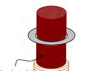

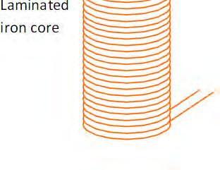
4 What is a TC? Double sided Thomson coil Single sided Thomson Coil Helix- shaped Thomson coil Single sided Thomson Coil with a concentrator
5 Theory i c = I sin( ω t) c B ( t ) = B c ( r, z ) sin ( ωt ) B B z r F z = = = B zsin( ωt) B rsin( ωt) i B φ r FTotal = ma

6 Modelling 2D axisymmetric model The Aluminum is in silver color, the coil turns are in red, the surrounding air in light blue
7 Static model (DC) 10kA constant current source connected across the terminals of a TC Constant magnetic field will be generated No eddy currents are induced in the aluminum disk Surface: Total Current density [A/m 2 ] Surface: Magnetic flux density [T] Contour: Magnetic vector potential [Wb/m] Arrow: Magnetic flux density
8 Stationary model (AC) Applied current: 10 ka Frequency: 1kHz Skin effect Proximity effect The magnetic flux density is concentrated in the air gap region between the coil and the aluminum disk
9 Transient multiphysics model The single sided TC is highly dependent on position of the aluminum disk As the disk moves away, the inductance, resistance, and induced currents change greatly influencing the exerted force A multiphysics model with a moving mesh is indispensible. COMSOL modules used: Azimuthal induction currents, and moving mesh (ALE) with dynamic remeshing. Setup Characteristics TC Capacitor bank 7 mf Initial voltage 400 V Al Cross section area 50 x 14 in (mm^2) Coil cross section area 2 mm x 4mm Air gap between coil and Al 1 mm Number of coil turns 9 Inter-distance coil turns 0.1 mm Stray resistance 10 mω Stray inductance 1 µh
10 Transient multiphysics model x 104 Capacitor voltag ge in volts (V) Force in newtons Time in milliseconds(ms) Time in milliseconds(ms) ) Current in amps(a) Displacement in millimeter ers (mm) Time in milliseconds(ms) Time in milliseconds(ms)
11 Transient multiphysics model Time: 0.18ms Arrow: magnetic field Surface: Total current density Time: 0.1ms Arrow: magnetic field Surface: Total current density Time: 0.3 ms Arrow: magnetic field Surface: Total current density
12 Transient multiphysics model Time: 0.18ms Contour lines: A [Wb/m] Surface: Magnetic flux density [T] Time: 0.1ms Contour lines: A [Wb/m] Surface: Magnetic flux density [T] Time: 0.3ms Contour lines: A [Wb/m] Surface: Magnetic flux density [T]
13 Transient multiphysics model Penetration depth wiith respect to time along the blue line

14 TC simulation 1 ABB Group November 23, 2010 Slide 14


15 TC simulation 2 ABB Group November 23, 2010 Slide 15


16 TC simulation 3 ABB Group November 23, 2010 Slide 16
17 Model verification Experimental verification is carried out to verify the results simulated in COMSOL. The results are compared with two experiments: Experiment I was already carried out at ABB Experiment II is the custom built prototype of the TC ABB Group November 23, 2010 Slide 17

18 Model verification Exp I Setup Characteristics Capacitor bank 33 mf Initial voltage 400 V Al Cross section area 50 mm x 20 mm Coil conductor cross section area 2 mm x 4 mm Air gap between coil and Al 1 mm Number of coil turns 10 Gap between coil turns 0.1 mm Stray resistance 10 mω Stray inductance 1 µh
19 Model verification Exp 2 Three series of tests were carried out: Test 1: The 33 mf capacitor bank is discharged in the coil with no aluminum ring on top at three voltage levels: 25, 50, and 100V Aim: Determine the stray impedance Step 1: The oscilloscope is used to measure the voltage and current pulse without any influence from the aluminum ring. Step 2:The resistance and inductance of the coil are determined by running a COMSOL simulation with no aluminum disk. Step3: The stray impedance can be approximated by solving for the following differential equations in MATLAB and comparing with the voltage and current waveforms measured in the lab:
20 Model verification Exp Current pulse at 50 V Scope Estimated dvc i = dt C di 1 = ( VC RStray i RTC i ) dt L + L Stray Curre ent in amps(a) Curre ent in amps(a) Scope Estimated ) Current in amps(a) Time in milliseconds(ms) Scope Estimated Time in milliseconds(ms) Current pulse at 25 V Time in milliseconds(ms) Current pulse at 100 V
21 Model verification Exp 2 Test 2: A Teflon cylinder is used to guide the aluminum ring. Test 3: The guide is removed to record the displacement of the aluminum disk without friction COMSOL Lab test run 1 Lab test run 2 Lab test run 3 2 Displaceme ent [mm] Time [ms]
22 Model verification Exp 2 The sources of error are: The coil is modeled as concentric rings in COMSOL and not as a spiral Air resistance is neglected The impedance of the coil is not 100% accurate The stray impedance is not constant The discharged voltage from the capacitor bank is not 100% exact : No need for a guide since the aluminum follows a straight trajectory. The model predicts the exerted forces on the aluminum disk with high accuracy.
23 Conclusions Static and stationary models serve as a good start to study the behavior and characteristics of a TC at different frequencies A single equivalent frequency in a stationary model is not sufficient This experimentally validated multiphysics finite element transient model can be used to design a TC to meet the needed requirements
24 Movies- TC 50 V No guide, No bottom damper ABB Group November 23, 2010 Slide 24
25 Movies- TC 150 V with guide and bottom damper ABB Group November 23, 2010 Slide 25
26 ABB Group November 23, 2010 Slide 26 Royal Institute of Technology
Multidomain Design and Optimization based on Comsol Multiphysics: Applications for Mechatronic Devices
 Multidomain Design and Optimization based on Comsol Multiphysics: Applications for Mechatronic Devices A. Bissal 1*, O. Craciun 2, V. Biagini 2, J. Magnusson 3 1 ABB AB Corporate Research, Västerås, Sweden
Postprint. This is the accepted version of a paper presented at ACTUATOR 2014, Bremen, Germany, June 2014.
 http://www.diva-portal.org Postprint This is the accepted version of a paper presented at ACTUATOR 0, Bremen, Germany, 5 June 0. Citation for the original published paper: Chen, C., Bissal, A., Salinas,
Electromagnetics in COMSOL Multiphysics is extended by add-on Modules
 AC/DC Module Electromagnetics in COMSOL Multiphysics is extended by add-on Modules 1) Start Here 2) Add Modules based upon your needs 3) Additional Modules extend the physics you can address 4) Interface
Modeling and Optimizing Ultra-fast Thomson-type Actuators for Electrical Switches
 Master's Degree Thesis ISRN: BTH-AMT-EX--2011/D-03--SE Modeling and Optimizing Ultra-fast Thomson-type Actuators for Electrical Switches Mohammadali Honarpardaz Department of Mechanical Engineering Blekinge
Modelling the Electrical Parameters Of A Loudspeaker Motor System With The AC-DC Module (MEPLMSAM)
") Modelling the Electrical Parameters Of A Loudspeaker Motor System With The AC-DC Module (MEPLMSAM) M. Cobianchi *1,Dr. M. Rousseau *1 and S. Xavier* 1 1 B&W Group Ltd, Worthing, West Sussex, England. *Corresponding
Modelling the Electrical Parameters Of A Loudspeaker Motor System With The AC-DC Module (MEPLMSAM) M. Cobianchi *1,Dr. M. Rousseau *1 and S. Xavier* 1 1 B&W Group Ltd, Worthing, West Sussex, England. *Corresponding
Work, Energy and Power
 1 Work, Energy and Power Work is an activity of force and movement in the direction of force (Joules) Energy is the capacity for doing work (Joules) Power is the rate of using energy (Watt) P = W / t,
CHAPTER 5 SIMULATION AND TEST SETUP FOR FAULT ANALYSIS
 47 CHAPTER 5 SIMULATION AND TEST SETUP FOR FAULT ANALYSIS 5.1 INTRODUCTION This chapter describes the simulation model and experimental set up used for the fault analysis. For the simulation set up, the
Physics 102, Learning Guide 4, Spring Learning Guide 4
 Physics 102, Learning Guide 4, Spring 2002 1 Learning Guide 4 z B=0.2 T y a R=1 Ω 1. Magnetic Flux x b A coil of wire with resistance R = 1Ω and sides of length a =0.2m and b =0.5m lies in a plane perpendicular
Multidomain Design and Optimization based on COMSOL Multiphysics: Applications for Mechatronic Devices Ara Bissal, Octavian Craciun, Veronica
 Multidomain Design and Optimization based on COMSOL Multiphysics: Applications for Mechatronic Devices Ara Bissal, Octavian Craciun, Veronica Biagini, & Jesper Magnusson Table of contents Introduction
MCE380: Measurements and Instrumentation Lab. Chapter 5: Electromechanical Transducers
 MCE380: Measurements and Instrumentation Lab Chapter 5: Electromechanical Transducers Part I Topics: Transducers and Impedance Magnetic Electromechanical Coupling Reference: Holman, CH 4. Cleveland State
Work, Energy and Power
 1 Work, Energy and Power Work is an activity of force and movement in the direction of force (Joules) Energy is the capacity for doing work (Joules) Power is the rate of using energy (Watt) P = W / t,
Philippe Wendling
 Flux: Transformers xxx Philippe Wendling info@tianyuantech.com Create,,Design, sg Engineer! www.magsoft-flux.com www.cedrat.com Possible analysis Modeling any type of industrial transformers: three-phase,
Induction_P1. 1. [1 mark]
![Induction_P1. 1. [1 mark]](/thumbs/88/115570773.jpg "Induction_P1. 1. [1 mark]") Induction_P1 1. [1 mark] Two identical circular coils are placed one below the other so that their planes are both horizontal. The top coil is connected to a cell and a switch. The switch is closed and
Induction_P1 1. [1 mark] Two identical circular coils are placed one below the other so that their planes are both horizontal. The top coil is connected to a cell and a switch. The switch is closed and
Revision Guide for Chapter 15
 Revision Guide for Chapter 15 Contents Revision Checklist Revision otes Transformer...4 Electromagnetic induction...4 Lenz's law...5 Generator...6 Electric motor...7 Magnetic field...9 Magnetic flux...
Revision Guide for Chapter 15
 Revision Guide for Chapter 15 Contents tudent s Checklist Revision otes Transformer... 4 Electromagnetic induction... 4 Generator... 5 Electric motor... 6 Magnetic field... 8 Magnetic flux... 9 Force on
Transient Finite Element Analysis of a Spice-Coupled Transformer with COMSOL-Multiphysics
 Presented at the COMSOL Conference 2010 Paris Thomas Bödrich 1, Holger Neubert 1, Rolf Disselnkötter 2 Transient Finite Element Analysis of a Spice-Coupled Transformer with COMSOL-Multiphysics 2010-11-17
Review of Basic Electrical and Magnetic Circuit Concepts EE
 Review of Basic Electrical and Magnetic Circuit Concepts EE 442-642 Sinusoidal Linear Circuits: Instantaneous voltage, current and power, rms values Average (real) power, reactive power, apparent power,
EXPERIMENT 07 TO STUDY DC RC CIRCUIT AND TRANSIENT PHENOMENA
 EXPERIMENT 07 TO STUDY DC RC CIRCUIT AND TRANSIENT PHENOMENA DISCUSSION The capacitor is a element which stores electric energy by charging the charge on it. Bear in mind that the charge on a capacitor
Solution for Fq. A. up B. down C. east D. west E. south
 Solution for Fq A proton traveling due north enters a region that contains both a magnetic field and an electric field. The electric field lines point due west. It is observed that the proton continues
Introduction. HFSS 3D EM Analysis S-parameter. Q3D R/L/C/G Extraction Model. magnitude [db] Frequency [GHz] S11 S21 -30
![Introduction. HFSS 3D EM Analysis S-parameter. Q3D R/L/C/G Extraction Model. magnitude [db] Frequency [GHz] S11 S21 -30](/thumbs/81/83311716.jpg "Introduction. HFSS 3D EM Analysis S-parameter. Q3D R/L/C/G Extraction Model. magnitude [db] Frequency [GHz] S11 S21 -30") ANSOFT Q3D TRANING Introduction HFSS 3D EM Analysis S-parameter Q3D R/L/C/G Extraction Model 0-5 -10 magnitude [db] -15-20 -25-30 S11 S21-35 0 1 2 3 4 5 6 7 8 9 10 Frequency [GHz] Quasi-static or full-wave
ANSOFT Q3D TRANING Introduction HFSS 3D EM Analysis S-parameter Q3D R/L/C/G Extraction Model 0-5 -10 magnitude [db] -15-20 -25-30 S11 S21-35 0 1 2 3 4 5 6 7 8 9 10 Frequency [GHz] Quasi-static or full-wave
Exercise 1: Capacitors
 Capacitance AC 1 Fundamentals Exercise 1: Capacitors EXERCISE OBJECTIVE When you have completed this exercise, you will be able to describe the effect a capacitor has on dc and ac circuits by using measured
Lecture 24. April 5 th, Magnetic Circuits & Inductance
 Lecture 24 April 5 th, 2005 Magnetic Circuits & Inductance Reading: Boylestad s Circuit Analysis, 3 rd Canadian Edition Chapter 11.1-11.5, Pages 331-338 Chapter 12.1-12.4, Pages 341-349 Chapter 12.7-12.9,
INSTITUTE OF AERONAUTICAL ENGINEERING Dundigal, Hyderabad Electronics and Communicaton Engineering
 INSTITUTE OF AERONAUTICAL ENGINEERING Dundigal, Hyderabad - 00 04 Electronics and Communicaton Engineering Question Bank Course Name : Electromagnetic Theory and Transmission Lines (EMTL) Course Code :
Review of DC Electric Circuit. DC Electric Circuits Examples (source:
 Review of DC Electric Circuit DC Electric Circuits Examples (source: http://hyperphysics.phyastr.gsu.edu/hbase/electric/dcex.html) 1 Review - DC Electric Circuit Multisim Circuit Simulation DC Circuit
Transformer Fundamentals
 Transformer Fundamentals 1 Introduction The physical basis of the transformer is mutual induction between two circuits linked by a common magnetic field. Transformer is required to pass electrical energy
RADIO AMATEUR EXAM GENERAL CLASS
 RAE-Lessons by 4S7VJ 1 CHAPTER- 2 RADIO AMATEUR EXAM GENERAL CLASS By 4S7VJ 2.1 Sine-wave If a magnet rotates near a coil, an alternating e.m.f. (a.c.) generates in the coil. This e.m.f. gradually increase
18 - ELECTROMAGNETIC INDUCTION AND ALTERNATING CURRENTS ( Answers at the end of all questions ) Page 1
 Page 1") ( Answers at the end of all questions ) Page ) The self inductance of the motor of an electric fan is 0 H. In order to impart maximum power at 50 Hz, it should be connected to a capacitance of 8 µ F (
( Answers at the end of all questions ) Page ) The self inductance of the motor of an electric fan is 0 H. In order to impart maximum power at 50 Hz, it should be connected to a capacitance of 8 µ F (
Sensibility Analysis of Inductance Involving an E-core Magnetic Circuit for Non Homogeneous Material
 Sensibility Analysis of Inductance Involving an E-core Magnetic Circuit for Non Homogeneous Material K. Z. Gomes *1, T. A. G. Tolosa 1, E. V. S. Pouzada 1 1 Mauá Institute of Technology, São Caetano do
Power and Energy Measurement
 Power and Energy Measurement EIE 240 Electrical and Electronic Measurement April 24, 2015 1 Work, Energy and Power Work is an activity of force and movement in the direction of force (Joules) Energy is
3 d Calculate the product of the motor constant and the pole flux KΦ in this operating point. 2 e Calculate the torque.
 Exam Electrical Machines and Drives (ET4117) 11 November 011 from 14.00 to 17.00. This exam consists of 5 problems on 4 pages. Page 5 can be used to answer problem 4 question b. The number before a question
What happens when things change. Transient current and voltage relationships in a simple resistive circuit.
 Module 4 AC Theory What happens when things change. What you'll learn in Module 4. 4.1 Resistors in DC Circuits Transient events in DC circuits. The difference between Ideal and Practical circuits Transient
ELECTRO MAGNETIC INDUCTION
 ELECTRO MAGNETIC INDUCTION 1) A Circular coil is placed near a current carrying conductor. The induced current is anti clock wise when the coil is, 1. Stationary 2. Moved away from the conductor 3. Moved
Thermal Analysis for the Solar Concentrating Energy and Induction Heating for Metals
 Thermal Analysis for the Solar Concentrating Energy and Induction Heating for Metals A. Rojas-Morín* 1, Y. Flores-Salgado 2, A. Barba-Pingarrón 1, R. Valdez-Navarro 1, F. Mendez 1, O. Álvarez-Brito 3,
Opening move. 30 times faster than the blink of an eye, simulating the extreme in HVDC switchgear
 30 times faster than the blink of an eye, simulating the extreme in HVDC switchgear Daniel Ohlsson, Jakub Korbel, Per Lindholm, Ueli Steiger, Per Skarby, Christian Simonidis, Sami Kotilainen One of ABB
Experiment Guide for RC Circuits
 Guide-P1 Experiment Guide for RC Circuits I. Introduction 1. Capacitors A capacitor is a passive electronic component that stores energy in the form of an electrostatic field. The unit of capacitance is
CHAPTER 6. Inductance, Capacitance, and Mutual Inductance
 CHAPTER 6 Inductance, Capacitance, and Mutual Inductance 6.1 The Inductor Inductance is symbolized by the letter L, is measured in henrys (H), and is represented graphically as a coiled wire. The inductor
Coupled Electrical Oscillators Physics Advanced Physics Lab - Summer 2018 Don Heiman, Northeastern University, 5/24/2018
 Coupled Electrical Oscillators Physics 3600 - Advanced Physics Lab - Summer 08 Don Heiman, Northeastern University, 5/4/08 I. INTRODUCTION The objectives of this experiment are: () explore the properties
Assessment Schedule 2015 Physics: Demonstrate understanding of electrical systems (91526)
") NCEA Level 3 Physics (91526) 2015 page 1 of 6 Assessment Schedule 2015 Physics: Demonstrate understanding of electrical systems (91526) Evidence Q Evidence Achievement Achievement with Merit Achievement
NCEA Level 3 Physics (91526) 2015 page 1 of 6 Assessment Schedule 2015 Physics: Demonstrate understanding of electrical systems (91526) Evidence Q Evidence Achievement Achievement with Merit Achievement
Chapter 15 Magnetic Circuits and Transformers
 Chapter 15 Magnetic Circuits and Transformers Chapter 15 Magnetic Circuits and Transformers 1. Understand magnetic fields and their interactio with moving charges. 2. Use the right-hand rule to determine
ELECTROMAGNETIC OSCILLATIONS AND ALTERNATING CURRENT
 Chapter 31: ELECTROMAGNETIC OSCILLATIONS AND ALTERNATING CURRENT 1 A charged capacitor and an inductor are connected in series At time t = 0 the current is zero, but the capacitor is charged If T is the
TRANSIENT NUMERICAL ANALYSIS OF INDUCTION HEATING OF GRAPHITE CRUCIBLE AT DIFFERENT FREQUENCY
 TRANSIENT NUMERICAL ANALYSIS OF INDUCTION HEATING OF GRAPHITE CRUCIBLE AT DIFFERENT FREQUENCY Abstract B. Patidar, M.M.Hussain, A. Sharma, A.P. Tiwari Bhabha Atomic Research Centre, Mumbai Mathematical
Switched Mode Power Conversion
 Inductors Devices for Efficient Power Conversion Switches Inductors Transformers Capacitors Inductors Inductors Store Energy Inductors Store Energy in a Magnetic Field In Power Converters Energy Storage
Inductance, Inductors, RL Circuits & RC Circuits, LC, and RLC Circuits
 Inductance, Inductors, RL Circuits & RC Circuits, LC, and RLC Circuits Self-inductance A time-varying current in a circuit produces an induced emf opposing the emf that initially set up the timevarying
Modelling, Simulation and Temperature Effect Analysis of Mutual Induction based High Temperature Level Sensor using COMSOL Multiphysics
 Modelling, Simulation and Temperature Effect Analysis of Mutual Induction based High Temperature Level Sensor using COMSOL Multiphysics Rajalakshmi R. Subhasis Dutta Bhabha Atomic Research Center, Mumbai
Contactless Excitation of MEMS Resonant Sensors by Electromagnetic Driving
 Excerpt from the Proceedings of the COMSOL Conference 2009 Milan Contactless Excitation of MEMS Resonant Sensors by Electromagnetic Driving M. Baù *, V. Ferrari, D. Marioli Department of Electronics for
RC Studies Relaxation Oscillator
 RC Studies Relaxation Oscillator Introduction A glass tube containing neon gas will give off its characteristic light when the voltage across the tube exceeds a certain value. The value corresponds to
Alternating Current. Chapter 31. PowerPoint Lectures for University Physics, Twelfth Edition Hugh D. Young and Roger A. Freedman
 Chapter 31 Alternating Current PowerPoint Lectures for University Physics, Twelfth Edition Hugh D. Young and Roger A. Freedman Lectures by James Pazun Modified by P. Lam 8_8_2008 Topics for Chapter 31
Keywords: Electric Machines, Rotating Machinery, Stator faults, Fault tolerant control, Field Weakening, Anisotropy, Dual rotor, 3D modeling
 Analysis of Electromagnetic Behavior of Permanent Magnetized Electrical Machines in Fault Modes M. U. Hassan 1, R. Nilssen 1, A. Røkke 2 1. Department of Electrical Power Engineering, Norwegian University
Electromagnetic Induction (Chapters 31-32)
") Electromagnetic Induction (Chapters 31-3) The laws of emf induction: Faraday s and Lenz s laws Inductance Mutual inductance M Self inductance L. Inductors Magnetic field energy Simple inductive circuits
Electromagnetic Induction (Chapters 31-3) The laws of emf induction: Faraday s and Lenz s laws Inductance Mutual inductance M Self inductance L. Inductors Magnetic field energy Simple inductive circuits
ECE 241L Fundamentals of Electrical Engineering. Experiment 5 Transient Response
 ECE 241L Fundamentals of Electrical Engineering Experiment 5 Transient Response NAME PARTNER A. Objectives: I. Learn how to use the function generator and oscilloscope II. Measure step response of RC and
Electromagnetic Induction & Inductors
 Electromagnetic Induction & Inductors 1 Revision of Electromagnetic Induction and Inductors (Much of this material has come from Electrical & Electronic Principles & Technology by John Bird) Magnetic Field
Time-Harmonic Modeling of Squirrel-Cage Induction Motors: A Circuit-Field Coupled Approach
 Time-Harmonic Modeling of Squirrel-Cage Induction Motors: A Circuit-Field Coupled Approach R. Escarela-Perez 1,3 E. Melgoza 2 E. Campero-Littlewood 1 1 División de Ciencias Básicas e Ingeniería, Universidad
An Optimised High Current Impulse Source
 An Optimised High Current Impulse Source S. Kempen, D. Peier Institute of High Voltage Engineering, University of Dortmund, Germany Abstract Starting from a predefined 8/0 µs impulse current, the design
MASSACHUSETTS INSTITUTE OF TECHNOLOGY Department of Physics 8.02 Spring 2003 Experiment 17: RLC Circuit (modified 4/15/2003) OBJECTIVES
 OBJECTIVES") MASSACHUSETTS INSTITUTE OF TECHNOLOGY Department of Physics 8. Spring 3 Experiment 7: R Circuit (modified 4/5/3) OBJECTIVES. To observe electrical oscillations, measure their frequencies, and verify energy
MASSACHUSETTS INSTITUTE OF TECHNOLOGY Department of Physics 8. Spring 3 Experiment 7: R Circuit (modified 4/5/3) OBJECTIVES. To observe electrical oscillations, measure their frequencies, and verify energy
Low Voltage Contact Electrostatic Discharge Phenomena
 Conf Presentation - >SESSION.PAPER< - replace with your Session & Paper # (DOUBLE-CLICK HERE TO EDIT) < 1 Low Voltage Contact Electrostatic Discharge Phenomena Tetsuji Oda, Yuto Ono, Hiraku Miyasaka Abstract
5SGA 15F2502. Gate turn-off Thyristor. V DRM = 2500 V I TGQM = 1500 A I TSM = 10 ka V T0 = 1.55 V r T = 0.63 mω V DClin = 1400 V
 V DRM = 2500 V I TGQM = 1500 A I TSM = 10 ka V T0 = 1.55 V r T = 0.63 mω V DClin = 1400 V Gate turn-off Thyristor 5SGA 15F2502 Doc. No. 5SYA 1214-01 Aug. 2000 Patented free-floating silicon technology
MODULE I. Transient Response:
 Transient Response: MODULE I The Transient Response (also known as the Natural Response) is the way the circuit responds to energies stored in storage elements, such as capacitors and inductors. If a capacitor
University of California, Berkeley Physics H7B Spring 1999 (Strovink) SOLUTION TO PROBLEM SET 11 Solutions by P. Pebler
 SOLUTION TO PROBLEM SET 11 Solutions by P. Pebler") University of California Berkeley Physics H7B Spring 999 (Strovink) SOLUTION TO PROBLEM SET Solutions by P. Pebler Purcell 7.2 A solenoid of radius a and length b is located inside a longer solenoid of
University of California Berkeley Physics H7B Spring 999 (Strovink) SOLUTION TO PROBLEM SET Solutions by P. Pebler Purcell 7.2 A solenoid of radius a and length b is located inside a longer solenoid of
SECOND ENGINEER REG III/2 MARINE ELECTRO-TECHNOLOGY. 1. Understands the physical construction and characteristics of basic components.
 SECOND ENGINEER REG III/ MARINE ELECTRO-TECHNOLOGY LIST OF TOPICS A B C D Electric and Electronic Components Electric Circuit Principles Electromagnetism Electrical Machines The expected learning outcome
Modelling Thomson Coils with Axis-symmetric Problems: Practical Accuracy Considerations
 TEC-65-16 1 Modelling Thomson Coils with Axis-symmetric Problems: Practical Accuracy Considerations D.S. Vilchis-Rodriguez, Member, IEEE, R. Shuttleworth, Member, IEEE and M. Barnes, Member, IEEE Abstract
Analysis of Geometrical Aspects of a Kelvin Probe
 Analysis of Geometrical Aspects of a Kelvin Probe Stefan Ciba 1, Alexander Frey 2 and Ingo Kuehne* 1 1 Heilbronn University, Institute for Fast Mechatronic Systems (ISM), Kuenzelsau, Germany 2 University
Equipotentials and Electric Fields
 Equipotentials and Electric Fields PURPOSE In this lab, we will investigate the relationship between the equipotential surfaces and electric field lines in the region around several different electrode
APPLICATION OF THE FINITE ELEMENT METHOD TO MODEL THE NONLINEAR VOICE COIL MOTION PRODUCED BY A LOUDSPEAKER MAGNET ASSEMBLY.
 APPLICATION OF THE FINITE ELEMENT METHOD TO MODEL THE NONLINEAR VOICE COIL MOTION PRODUCED BY A LOUDSPEAKER MAGNET ASSEMBLY. Mark Dodd Celestion International & KEF Audio (UK) Ltd. 1. INTRODUCTION Moving
a. Clockwise. b. Counterclockwise. c. Out of the board. d. Into the board. e. There will be no current induced in the wire
 Physics 1B Winter 2012: Final Exam For Practice Version A 1 Closed book. No work needs to be shown for multiple-choice questions. The first 10 questions are the makeup Quiz. The remaining questions are
Basic Electronics. Introductory Lecture Course for. Technology and Instrumentation in Particle Physics Chicago, Illinois June 9-14, 2011
 Basic Electronics Introductory Lecture Course for Technology and Instrumentation in Particle Physics 2011 Chicago, Illinois June 9-14, 2011 Presented By Gary Drake Argonne National Laboratory drake@anl.gov
ELECTRICITY AND MAGNETISM, A. C. THEORY AND ELECTRONICS, ATOMIC AND NUCLEAR PHYSICS
 UNIT 2: ELECTRICITY AND MAGNETISM, A. C. THEORY AND ELECTRONICS, ATOMIC AND NUCLEAR PHYSICS MODULE 1: ELECTRICITY AND MAGNETISM GENERAL OBJECTIVES On completion of this Module, students should: 1. understand
PHYS 241 EXAM #2 November 9, 2006
 1. ( 5 points) A resistance R and a 3.9 H inductance are in series across a 60 Hz AC voltage. The voltage across the resistor is 23 V and the voltage across the inductor is 35 V. Assume that all voltages
Experiment 5. Simple Harmonic Motion
 Reading and Problems: Chapters 7,8 Problems 7., 8. Experiment 5 Simple Harmonic Motion Goals. To understand the properties of an oscillating system governed by Hooke s Law.. To study the effects of friction
AC Circuits. The Capacitor
 The Capacitor Two conductors in close proximity (and electrically isolated from one another) form a capacitor. An electric field is produced by charge differences between the conductors. The capacitance
5SGA 20H2501. Gate turn-off Thyristor. V DRM = I TGQM = 2000 A I TSM = 16 ka V T0 = 1.66 V r T = 0.57 mω V DClin = 1400 V
 V DRM = 25 V I TGQM = 2 A I TSM = 16 ka V T = 1.66 V r T =.57 mω V DClin = 14 V Gate turn-off Thyristor Doc. No. 5SYA125-1 Jun. 4 Patented free-floating silicon technology Low on-state and switching losses
Magnetic Field Analysis
 NISA - EMAG EMAG is the electromagnetic module of the family of general purpose finite element based program NISA. It can determine electric and magnetic field distributions in a wide class of electromagnetic
5SGF 30J4502. Gate turn-off Thyristor PRELIMINARY. V DRM = 4500 V I TGQM = 3000 A I TSM = 24 ka V T0 = 1.80 V r T = 0.70 mω V DClin = 3000 V
 V DRM = 4500 V I TGQM = 3000 A I TSM = 24 ka V T0 = 1.80 V r T = 0.70 mω V DClin = 3000 V Gate turn-off Thyristor 5SGF 30J4502 PRELIMINARY Doc. No. 5SYA 1211-04 Aug. 2000 Patented free-floating silicon
Dynamic simulation of a coaxial magnetic gear using global ODE's and DAE s and the rotating machinery, magnetic interface
 Dynamic simulation of a coaxial magnetic gear using global ODE's and DAE s and the rotating machinery, magnetic interface M. Ostroushko 1, W. Zhang 1, W. M. Rucker 1 1. Institute of Theory of Electrical
Solutions to these tests are available online in some places (but not all explanations are good)...
...") The Physics GRE Sample test put out by ETS https://www.ets.org/s/gre/pdf/practice_book_physics.pdf OSU physics website has lots of tips, and 4 additional tests http://www.physics.ohiostate.edu/undergrad/ugs_gre.php
The Physics GRE Sample test put out by ETS https://www.ets.org/s/gre/pdf/practice_book_physics.pdf OSU physics website has lots of tips, and 4 additional tests http://www.physics.ohiostate.edu/undergrad/ugs_gre.php
CHAPTER FOUR MUTUAL INDUCTANCE
 CHAPTER FOUR MUTUAL INDUCTANCE 4.1 Inductance 4.2 Capacitance 4.3 Serial-Parallel Combination 4.4 Mutual Inductance 4.1 Inductance Inductance (L in Henry is the circuit parameter used to describe an inductor.
1. An isolated stationary point charge produces around it. a) An electric field only. b) A magnetic field only. c) Electric as well magnetic fields.
 An electric field only. b) A magnetic field only. c) Electric as well magnetic fields.") 1. An isolated stationary point charge produces around it. a) An electric field only. b) A magnetic field only. c) Electric as well magnetic fields. 2. An isolated moving point charge produces around it.
1. An isolated stationary point charge produces around it. a) An electric field only. b) A magnetic field only. c) Electric as well magnetic fields. 2. An isolated moving point charge produces around it.
Sliding Conducting Bar
 Motional emf, final For equilibrium, qe = qvb or E = vb A potential difference is maintained between the ends of the conductor as long as the conductor continues to move through the uniform magnetic field
Module 4: Dynamic Vibration Absorbers and Vibration Isolator Lecture 19: Active DVA. The Lecture Contains: Development of an Active DVA
 The Lecture Contains: Development of an Active DVA Proof Mass Actutor Application of Active DVA file:///d /chitra/vibration_upload/lecture19/19_1.htm[6/25/2012 12:35:51 PM] In this section, we will consider
Chapter 4 Transients. Chapter 4 Transients
 Chapter 4 Transients Chapter 4 Transients 1. Solve first-order RC or RL circuits. 2. Understand the concepts of transient response and steady-state response. 1 3. Relate the transient response of first-order
Sinusoidal Response of RLC Circuits
 Sinusoidal Response of RLC Circuits Series RL circuit Series RC circuit Series RLC circuit Parallel RL circuit Parallel RC circuit R-L Series Circuit R-L Series Circuit R-L Series Circuit Instantaneous
Driven RLC Circuits Challenge Problem Solutions
 Driven LC Circuits Challenge Problem Solutions Problem : Using the same circuit as in problem 6, only this time leaving the function generator on and driving below resonance, which in the following pairs
Physics 2B Spring 2010: Final Version A 1 COMMENTS AND REMINDERS:
 Physics 2B Spring 2010: Final Version A 1 COMMENTS AND REMINDERS: Closed book. No work needs to be shown for multiple-choice questions. 1. A charge of +4.0 C is placed at the origin. A charge of 3.0 C
MULTIPLE CHOICE. Choose the one alternative that best completes the statement or answers the question.
 Exam Name MULTIPLE CHOICE. Choose the one alternative that best completes the statement or answers the question. 1) A jeweler needs to electroplate gold (atomic mass 196.97 u) onto a bracelet. He knows
Prof. Krishna Vasudevan, Prof. G. Sridhara Rao, Prof. P. Sasidhara Rao
 2 Basic Principles As mentioned earlier the transformer is a static device working on the principle of Faraday s law of induction. Faraday s law states that a voltage appears across the terminals of an
ELECTROMANETIC PULSE PROPAGATION IN A COAXIAL CABLE
 ELECTROMANETIC PULSE PROPAGATION IN A COAXIAL CABLE The mechanical waves on a stretched string are easily generated and observed but not easily studied in quantitative detail. The propagating waves in
BE 3600 BIOMEDICAL INSTRUMENTATION (LAB) - WEEK 2
 - WEEK 2") BE 3600 BIOMEDICAL INSTRUMENTATION (LAB) - WEEK 2 Principles of Biosensors OBJECTIVE: Learn the various modalities for construction of sensors utilizing electrical and optical measurement techniques. EXPERIMENT
BE 3600 BIOMEDICAL INSTRUMENTATION (LAB) - WEEK 2 Principles of Biosensors OBJECTIVE: Learn the various modalities for construction of sensors utilizing electrical and optical measurement techniques. EXPERIMENT
Electrostatics. Apparatus:
 Electrostatics Object: This experiment allows you to investigate the production of static charge, conservation of charge and the behavior of charges on conductors, which are interacting via Coulomb forces.
Inductance, RL Circuits, LC Circuits, RLC Circuits
 Inductance, R Circuits, C Circuits, RC Circuits Inductance What happens when we close the switch? The current flows What does the current look like as a function of time? Does it look like this? I t Inductance
PROBLEMS TO BE SOLVED IN CLASSROOM
 PROLEMS TO E SOLVED IN LSSROOM Unit 0. Prerrequisites 0.1. Obtain a unit vector perpendicular to vectors 2i + 3j 6k and i + j k 0.2 a) Find the integral of vector v = 2xyi + 3j 2z k along the straight
Power and Energy Measurement
 Power and Energy Measurement ENE 240 Electrical and Electronic Measurement Class 11, February 4, 2009 werapon.chi@kmutt.ac.th 1 Work, Energy and Power Work is an activity of force and movement in the direction
Flux: Examples of Devices
 Flux: Examples of Devices xxx Philippe Wendling philippe.wendling@magsoft-flux.com Create, Design, Engineer! www.magsoft-flux.com www.cedrat.com Solenoid 2 1 The Domain Axisymmetry Open Boundary 3 Mesh
Numerical Simulation and Experimental Study of Electromagnetic Forming
 11 th International LS-DYNA Users Conference Metal Forming Numerical Simulation and Experimental Study of Electromagnetic Forming Jianhui Shang 1, Pierre L Eplattenier 2, Larry Wilkerson 1, Steve Hatkevich
Electricity & Magnetism Study Questions for the Spring 2018 Department Exam December 4, 2017
 Electricity & Magnetism Study Questions for the Spring 2018 Department Exam December 4, 2017 1. a. Find the capacitance of a spherical capacitor with inner radius l i and outer radius l 0 filled with dielectric
Homework due next Tuesday 11:59 PM Next Sunday: no in-person office hour (try a skype office hour 7:45 8:15?)
") Homework due next Tuesday 11:59 PM Next Sunday: no in-person office hour (try a skype office hour 7:45 8:15?) SUNDAY Nov 18: SECOND HOUR EXAM 6:10-7:30 PM in SEC 111 (Ch. 26-30) -- no recitations the previous
Homework due next Tuesday 11:59 PM Next Sunday: no in-person office hour (try a skype office hour 7:45 8:15?) SUNDAY Nov 18: SECOND HOUR EXAM 6:10-7:30 PM in SEC 111 (Ch. 26-30) -- no recitations the previous
AP Physics C Mechanics Objectives
 AP Physics C Mechanics Objectives I. KINEMATICS A. Motion in One Dimension 1. The relationships among position, velocity and acceleration a. Given a graph of position vs. time, identify or sketch a graph
ENGG4420 LECTURE 7. CHAPTER 1 BY RADU MURESAN Page 1. September :29 PM
 CHAPTER 1 BY RADU MURESAN Page 1 ENGG4420 LECTURE 7 September 21 10 2:29 PM MODELS OF ELECTRIC CIRCUITS Electric circuits contain sources of electric voltage and current and other electronic elements such
TRANSFORMERS B O O K P G
 TRANSFORMERS B O O K P G. 4 4 4-449 REVIEW The RMS equivalent current is defined as the dc that will provide the same power in the resistor as the ac does on average P average = I 2 RMS R = 1 2 I 0 2 R=
Chapter 23: Magnetic Flux and Faraday s Law of Induction
 Chapter 3: Magnetic Flux and Faraday s Law of Induction Answers Conceptual Questions 6. Nothing. In this case, the break prevents a current from circulating around the ring. This, in turn, prevents the
AC Circuits III. Physics 2415 Lecture 24. Michael Fowler, UVa
 AC Circuits III Physics 415 Lecture 4 Michael Fowler, UVa Today s Topics LC circuits: analogy with mass on spring LCR circuits: damped oscillations LCR circuits with ac source: driven pendulum, resonance.
Ch. 23 Electromagnetic Induction, AC Circuits, And Electrical Technologies
 Ch. 23 Electromagnetic Induction, AC Circuits, And Electrical Technologies Induced emf - Faraday s Experiment When a magnet moves toward a loop of wire, the ammeter shows the presence of a current When