Philippe Wendling
|
|
|
- Alisha Edwards
- 6 years ago
- Views:
Transcription


1 Flux: Transformers xxx Philippe Wendling Create,,Design, sg Engineer!


 References ABB, Alstom, Electricité De")

2 Possible analysis Modeling any type of industrial transformers: three-phase, single-phase, auto transformer, reactors.. Simulating classical tests: Analyzing No-load Short-circuit i Inrush current Iron losses Stray losses Joule losses Magnetizing reactance Performing thermal and mechanical analysis Multiphysics (3 rd party tools) References ABB, Alstom, Electricité De France (EDF), Federal Mogul, General Electric, Hydro Quebec, Iskra Stikala, Sh Schneider Electric, Trafomec, Trasfor, Transrail, VATech, Westinghouse 2

3 Transformers Geometry: Direct Input Import Full or reduced model ¼th 3-phase transformer 3
4 Physical domain in Flux Steady state AC magnetic: Flux: Transformers and Coils common tests (short circuit, open circuit, rated conditions) Single Frequency/Harmonic Transient Magnetic: common tests (short circuit, open circuit, rated conditions) Full signal Steady state thermal : thermal behavior 4


5 An example: HV transformer 150 MVA kv / 14.1 kv Flux Model: (courtesy of WTC) Flux: Transformers and Coils The Electric Circuit V1 HV_1 LV_1 R1 V2 HV_2 LV_2 R2 V3 HV_3 LV_3 R3 5
6 Flux: Transformers and Coils Transformer Flux region Description Core, Shunts: Laminated Tank frames: δ<<sheet thickness Shunt for fastening: thin sheet thickness Conductive parts with eddy current Windings, Bus bars, current sources, no eddy currents Magnetic non conductive volume region Surface impedance (face region) Thin conducting surface region Solid conductor volume region Coil conductor volume region or non meshed coils µr µr, ρ µr, ρ thickness µr, ρ Coil component Number of turns 6
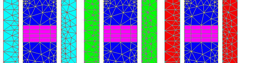
7 Modeling of laminated magnetic core Allows reducing the eddy current losses in Flux Problem of dimensional disproportion (sheet length compared to the sheet thickness) Need to simplify the model 7


8 Equivalent macroscopic model Simplifying i by homogenization i the block of insulated laminations is replaced by a homogeneous block takes into consideration anisotropy, saturation and eddy currents technique Ongoing PhD work taking into account forbidden current loops (paper) User version Lamination available in Flux 3D permits the modeling of the ferromagnetic material by means of the Analytical anisotropic saturation 8
 Meshed coils : Coil conductor volume region Simplification")
 3) Meshed coils : representing every conductor (only for specific")
9 Windings definitions iti 1) Non-meshed coils Fast computation Independent from the mesh 2) Meshed coils : Coil conductor volume region Simplification of the representation as an homogeneous volume region (if thin wires and many turns) 3) Meshed coils : representing every conductor (only for specific studies) 9
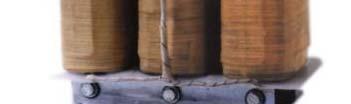
10 Real transformer model Transformer model parameters 10


11 Flux - Transformer See how it works! 11
12 Open Circuit it Open Circuit Test Case (No Load) Magnetizing current in the primary Saturated core Neglected leakages V1 HV_1 LV_1 R1 R>>1 I=0A V2 HV_2 LV_2 R2 V3 HV_3 LV_3 R3 12

: 416")
13 Open Circuit it Color shades of B Arrows of B Joule losses on the tank: 10 W Energy on the domain: 73 Joules Magnetizing reactance Iron losses on the core (Bertotti): 416 Joules 13
14 Open Circuit it Flux Computes Results Current in each primary phase Magnetic energy E on the domain Magnetizing current Reactive power/phase E=1/2*L*I² Qtot=2*E*ω Q=Qtot/3 X_1=Q/(I_1)² Magnetizing reactance Xm1, Xm2 Magnetic flux density in core + Bertotti tti coefficients i Iron Losses 14
15 Principle Magnetizing current neglected Core non saturated low flux density Large flux leakage Short-circuit it test t simulation V1 HV_1 LV_1 R1 R<<1 U=0 V2 HV_2 LV_2 R2 V3 HV_3 LV_3 R3 15
16 Short-circuit it test t simulation Color shades of B Arrows of B Joule losses on the tank: 1395 W Stray losses Energy on the domain: 1024 Joules Leakage Reactance Laplace forces Joule losses in the windings 16
17 Short-circuit it test t simulation Flux computes Voltage in each primary phase Magnetic energy E on the domain R1, R2, I1, I2 Radial magnetic induction Stray losses density Short-circuit voltages Results Reactive power/phase p E=1/2*L*I² Qtot=2*E*ω Q=Qtot/3 X_1=Q/(I_1)² Leakage reactance X1, X2 Pj=3*R1*I1²+3*R2*I2² Joule losses in the winding Eddy current losses in the winding Total Stray losses 17


18 Stray losses Flux leakage ~Eddy current in conductive parts ~Joule losses - «Stray losses» In Flux use of surface impedance region Short-circuit it test t simulation 18
 1 b sinh( a / δ ) sin( a / δ )")

19 Eddy current losses in the winding Short-circuit it test t simulation Losses per conductor per winding linked to radial magnetic induction Brad In Flux: export on 2D grid of B in the coil use formula P( eddy) 1 b sinh( a / δ ) sin( a / δ ) 2 a sinh( b / δ ) sin( b / δ ) + 2 cosh( a / ) + cos( a / ) Brad σ μ δ δ δ δ cosh( b / δ ) + cos( b / δ ) b 2 = Bax o This methods refer to : Calculation lation of Extra losses in shell transformers s windings, T.Ngneugueu, IEEE,
 = cos(2wt).f21+sin(2wt).")
 DF Laplace/DV 2w = Pulsating component F2(t) (double frequency)")
20 Laplace forces analysis Definition df(t)=pvec(j,b) = F1+F2(t) with F1 = 1/2Re(JxB*) and F2(t) = cos(2wt).f21+sin(2wt).f22 Display color shades or arrows of Laplace force density on coils DF Laplace/DV = Component F1 (Fundamental) DF Laplace/DV 2w = Pulsating component F2(t) (double frequency) Compute total force Integral of the above quantities in all coils 20
21 Export Joule losses from short-circuit simulation Thermal analysis of heating For example the Joule losses on the tank Define a Steady State Thermal application Use of thin conducting region with ihexchange and thermal source Create a spatial parameter for import Imported losses will be used as heat source 21
22 Example Eddy Currents Computation of eddy currents in tank Surface Impedance formulation 22
23 Power Transformer A three-phase h transformer with an air core reactor inside id of the tank was considered as the application of this analysis 23
24 Objectives Calculate eddy current losses in the clamping plate, tank and electromagnetic shielding of a power transformer using FLUX3D Analyze the effects of electromagnetic shielding and magnetic shunts on the eddy current loss reduction in the transformer tank 24
25 Surface Impedance Method The 3D Time-Harmonic Magnetodynamic Formulation was used in this analysis This formulation takes into account the currents induced in the conducting regions (eddy currents) and also considers the skin effects and the proximity effects in the conducting regions. Some devices such as clamping plate, bus bars of transformers and shielding are mainly made up of sheet or line type parts of thin air-gaps. Modeling these parts using traditional finite volume elements available in 3D software is tiresome, and even impossible. Moreover, the skin effect in ferromagnetic materials increases the difficulties of meshing eddy current problems in under sinusoidal conditions. 25
26 Surface Impedance Method An alternative to this difficulty of meshing the thin regions is the use special shell elements for the modeling of magnetic or thin conducting regions, and surface impedance elements for the modeling of conducting regions having a strong skin depth Special surface elements, using the concept of surface impedance, which describe the surface of the conducting region, allow the exponential decay to be taken into account. They also allow the magnetic field to only be calculated on the surface and outside 26
27 Power Transformer Description The tank and the clamping plates are made of mild steel (modeled by Surface Impedance Method - SIM) The core and the magnetic shunts are made of silicon-steel laminations The tank wall (side A) was modeled considering three cases: No Shielding Aluminum Electromagnetic Shielding (modeled by SIM) Magnetic Shunts 27
28 FLUX-3D Geometry Electromagnetic Shielding 28
29 FLUX-3D Geometry Magnetic Shunts 29
30 FLUX-3D Coupled Circuit it Electrical circuit feeding the active part of the transformer Electrical circuit coupled to the winding of the air core reactor 30
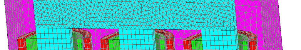
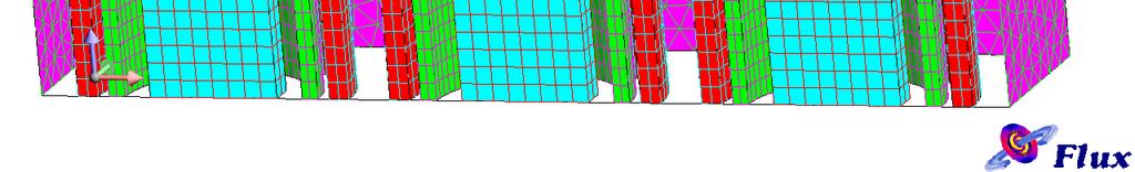
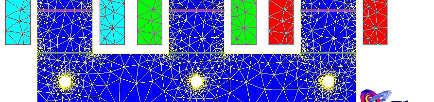
31 FLUX-3D Mesh 31
32 RESULTS 32
33 Magnetic Field Distribution ib ti in the Oil No Shielding There is only tangential ti component of the magnetic field in the tank walls (modeled by Surface Impedance) 33
34 Magnetic Field Distribution ib ti in the Oil Aluminum Electromagnetic Shielding There is only tangential component of the magnetic field in the tank walls and Electromagnetic Shielding (modeled by Surface Impedance) 34
35 Magnetic Field Distribution ib ti in the Oil Magnetic Shunts The magnetic flux tends to pass through the shunts 35
36 Eddy Current Losses in the Transformer Tank No Shielding The eddy current losses in the tank are larger in this first case 36
37 Eddy Current Losses in the Transformer Tank Aluminum Electromagnetic Shielding The eddy current losses in the tank are reduced in this second case 37
38 Eddy Current Losses in the Transformer Tank Magnetic Shunts The tank wall protected by the magnetic shunts has a loss concentration bigger than the tank wall protected by the aluminum electromagnetic shielding 38
39 Thermal Image of the Tank Wall with Magnetic Shunts One can see the presence of hot spots in position behind the magnetic shunts (red region). This shows that the magnetic shunts concentrate ce the eddy current losses at the top of shunts 39


40 Transformer winding HV winding Leg A Leg B The winding on leg A and B are parallel connected. LV winding has 2 layers for each leg and 2 layers are series connected with each other. LV winding 40
41 Eddy Current Losses in Coils 1 54 HV TAP HV HV TAP HV Section1 to section 54 are series. Section55 to section 108 are series. Then, upper and lower part are parallel connected. Each section is consist with 9-turn continuously transposed conductors (CTC). 55 HV leg HV A TAP TAP HV HV 108 CTC Single section 41
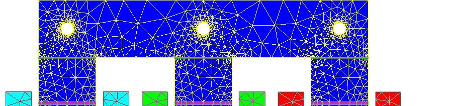
42 FLUX MODEL Axisymmetric i Just take 3 sections of HV winding and 1 section of LV winding. core A for this area /2 A for this area 42
43 External circuit it LV HV 43
44 Current density - hv DC 60Hz 44
45 Current density - lv DC 60 Hz 45
46 Joule Losses vs. Frequency on HV 46


47 Thank you for your interest in our modelling solutions 47
Flux: Examples of Devices
 Flux: Examples of Devices xxx Philippe Wendling philippe.wendling@magsoft-flux.com Create, Design, Engineer! www.magsoft-flux.com www.cedrat.com Solenoid 2 1 The Domain Axisymmetry Open Boundary 3 Mesh
Electromagnetic Analysis Applied to the Prediction of Stray Losses in Power Transformer
 Electromagnetic Analysis Applied to the Prediction of Stray Losses in Power Transformer L. Susnjic 1), Z. Haznadar 2) and Z. Valkovic 3) 1) Faculty of Engineering Vukovarska 58, 5 Rijeka, Croatia, e-mail:
Eddy Current Losses in the Tank Wall of Power Transformers
 Eddy Current Losses in the Tank Wall of Power Transformers Erich Schmidt Institute of Electrical Drives and Machines, Vienna University of Technology A 14 Vienna, Austria, Gusshausstrasse 25 29 Phone:
Electromagnetics in COMSOL Multiphysics is extended by add-on Modules
 AC/DC Module Electromagnetics in COMSOL Multiphysics is extended by add-on Modules 1) Start Here 2) Add Modules based upon your needs 3) Additional Modules extend the physics you can address 4) Interface
Coupled electromagnetic, thermal and stress analysis of large power electrical transformers
 Coupled electromagnetic, thermal and stress analysis of large power electrical transformers DANIELA CÂRSTEA High-School Group of Railways, Craiova ROMANIA ALEXANDRU ADRIAN CÂRSTEA University of Craiova
Review of Basic Electrical and Magnetic Circuit Concepts EE
 Review of Basic Electrical and Magnetic Circuit Concepts EE 442-642 Sinusoidal Linear Circuits: Instantaneous voltage, current and power, rms values Average (real) power, reactive power, apparent power,
Analysis of Stray Losses Calculation in Auto-Transformer Using Coupled IEM and FEM Technique
 Analysis of Stray Losses Calculation in Auto-Transformer Using Coupled IEM and FEM Technique Ankit M. Patel 1, Aniruddha S. Jhala 2, Hitesh M. Karkar 3 1 M.E Student, Electrical Dept., Atmiya Institute
MODELING AND MODIFICATION FOR DISTRIBUTION TRANSFORMER (250 KVA, 11/0.416 KV) TO REDUCE THE TOTAL LOSSES
 TO REDUCE THE TOTAL LOSSES") MODELING AND MODIFICATION FOR DISTRIBUTION TRANSFORMER (250 KVA, 11/0.416 KV) TO REDUCE THE TOTAL LOSSES Assist. Prof. Ibtisam A. Hasan Dr. Sahar R. Fafraj Eng. Azhar K. Azeez Electromechanical Eng. Dept.
MODELING AND MODIFICATION FOR DISTRIBUTION TRANSFORMER (250 KVA, 11/0.416 KV) TO REDUCE THE TOTAL LOSSES Assist. Prof. Ibtisam A. Hasan Dr. Sahar R. Fafraj Eng. Azhar K. Azeez Electromechanical Eng. Dept.
Transformer Fundamentals
 Transformer Fundamentals 1 Introduction The physical basis of the transformer is mutual induction between two circuits linked by a common magnetic field. Transformer is required to pass electrical energy
ROEVER COLLEGE OF ENGINEERING & TECHNOLOGY ELAMBALUR, PERAMBALUR DEPARTMENT OF ELECTRICAL AND ELECTRONICS ENGINEERING ELECTRICAL MACHINES I
 ROEVER COLLEGE OF ENGINEERING & TECHNOLOGY ELAMBALUR, PERAMBALUR-621220 DEPARTMENT OF ELECTRICAL AND ELECTRONICS ENGINEERING ELECTRICAL MACHINES I Unit I Introduction 1. What are the three basic types
Sensibility Analysis of Inductance Involving an E-core Magnetic Circuit for Non Homogeneous Material
 Sensibility Analysis of Inductance Involving an E-core Magnetic Circuit for Non Homogeneous Material K. Z. Gomes *1, T. A. G. Tolosa 1, E. V. S. Pouzada 1 1 Mauá Institute of Technology, São Caetano do
Equivalent Circuits with Multiple Damper Windings (e.g. Round rotor Machines)
") Equivalent Circuits with Multiple Damper Windings (e.g. Round rotor Machines) d axis: L fd L F - M R fd F L 1d L D - M R 1d D R fd R F e fd e F R 1d R D Subscript Notations: ( ) fd ~ field winding quantities
Equivalent Circuits with Multiple Damper Windings (e.g. Round rotor Machines) d axis: L fd L F - M R fd F L 1d L D - M R 1d D R fd R F e fd e F R 1d R D Subscript Notations: ( ) fd ~ field winding quantities
Module 3 : Sequence Components and Fault Analysis
 Module 3 : Sequence Components and Fault Analysis Lecture 12 : Sequence Modeling of Power Apparatus Objectives In this lecture we will discuss Per unit calculation and its advantages. Modeling aspects
Electric Power Systems Research
 Electric Power Systems Research 78 (2008) 84 88 Contents lists available at ScienceDirect Electric Power Systems Research journal homepage: www.elsevier.com/locate/epsr 3D finite-element determination
Assessing COMSOL Performances on Typical Electromagnetic Problems Faced by Turbo-Generator Manufacturers
 1 Assessing COMSOL Performances on Typical Electromagnetic Problems Faced by Turbo-Generator Manufacturers E. A. Badea *1, J. Oesterheld 1, S. Friedel 2 and M. Olsson 2 1 Alstom (Switzerland) LTD, 2 COMSOL
An Introduction to Electrical Machines. P. Di Barba, University of Pavia, Italy
 An Introduction to Electrical Machines P. Di Barba, University of Pavia, Italy Academic year 0-0 Contents Transformer. An overview of the device. Principle of operation of a single-phase transformer 3.
Induction Motors. The single-phase induction motor is the most frequently used motor in the world
 Induction Motor The single-phase induction motor is the most frequently used motor in the world Most appliances, such as washing machines and refrigerators, use a single-phase induction machine Highly
The Effect of Harmonic Distortion on a Three phase Transformer Losses
 The Effect of Harmonic Distortion on a Three phase Transformer Losses Hussein I. Zynal, Ala'a A. Yass University of Mosul Abstract-Electrical transformers are designed to work at rated frequency and sinusoidal
PESIT Bangalore South Campus Hosur road, 1km before Electronic City, Bengaluru -100 Department of Electronics & Communication Engineering
 QUESTION PAPER INTERNAL ASSESSMENT TEST 2 Date : /10/2016 Marks: 0 Subject & Code: BASIC ELECTRICAL ENGINEERING -15ELE15 Sec : F,G,H,I,J,K Name of faculty : Dhanashree Bhate, Hema B, Prashanth V Time :
Introduction to Synchronous. Machines. Kevin Gaughan
 Introduction to Synchronous Machines Kevin Gaughan The Synchronous Machine An AC machine (generator or motor) with a stator winding (usually 3 phase) generating a rotating magnetic field and a rotor carrying
Tutorial Sheet Fig. Q1
 Tutorial Sheet - 04 1. The magnetic circuit shown in Fig. Q1 has dimensions A c = A g = 9 cm 2, g = 0.050 cm, l c = 30 cm, and N = 500 turns. Assume the value of the relative permeability,µ r = 70,000
EN Power Electronics and Machines
 1/19 - Power Electronics and Machines Transformers Suryanarayana Doolla Department of Energy Science and Engineering Indian Institute of Technology, Bombay suryad@iitb.ac.in Lecture Organization - Modules
Induction Heating: fundamentals
 LEP ELECTROMAGNETIC PROCESSING OF MATERIALS TECNOLGIE DEI PROCESSI ELETTROTERMICI Induction Heating: fundamentals Fabrizio Dughiero 2017-2018 Induction heating fundamentals May 28-30, 2014 1 Summary 1.
The synchronous machine (detailed model)
") ELEC0029 - Electric Power System Analysis The synchronous machine (detailed model) Thierry Van Cutsem t.vancutsem@ulg.ac.be www.montefiore.ulg.ac.be/~vct February 2018 1 / 6 Objectives The synchronous
ELEC0029 - Electric Power System Analysis The synchronous machine (detailed model) Thierry Van Cutsem t.vancutsem@ulg.ac.be www.montefiore.ulg.ac.be/~vct February 2018 1 / 6 Objectives The synchronous
Finite Element Method based investigation of IPMSM losses
 Finite Element Method based investigation of IPMSM losses Martin Schmidtner 1, Prof. Dr. -Ing. Carsten Markgraf 1, Prof. Dr. -Ing. Alexander Frey 1 1. Augsburg University of Applied Sciences, Augsburg,
EE Branch GATE Paper 2010
 Q.1 Q.25 carry one mark each 1. The value of the quantity P, where, is equal to 0 1 e 1/e 2. Divergence of the three-dimensional radial vector field is 3 1/r 3. The period of the signal x(t) = 8 is 0.4
UNIT I INTRODUCTION Part A- Two marks questions
 ROEVER COLLEGE OF ENGINEERING & TECHNOLOGY ELAMBALUR, PERAMBALUR-621220 DEPARTMENT OF ELECTRICAL AND ELECTRONICS ENGINEERING DESIGN OF ELECTRICAL MACHINES UNIT I INTRODUCTION 1. Define specific magnetic
RNM2D_0 Fast Stray Losses Hazard Evaluation on Transformer Tank Wall & Cover due to Zero Sequence
 RNM2D_0 Fast Stray Losses Hazard Evaluation on Transformer Tank Wall & Cover due to Zero Sequence Xose M. LOPEZ-FERNANDEZ, Casimiro ALVAREZ-MARIÑO and Patricia PENABAD-DURAN Department of Electrical Engineering,
Large-Scale 3D Electromagnetic Field Analysis for Estimation of Stator End Region Loss in Turbine Generators
 IEEJ Journal of Industry Applications Vol.6 No.6 pp.340 345 DOI: 10.1541/ieejjia.6.340 Paper Large-Scale 3D Electromagnetic Field Analysis for Estimation of Stator End Region Loss in Turbine Generators
SECOND ENGINEER REG III/2 MARINE ELECTRO-TECHNOLOGY. 1. Understands the physical construction and characteristics of basic components.
 SECOND ENGINEER REG III/ MARINE ELECTRO-TECHNOLOGY LIST OF TOPICS A B C D Electric and Electronic Components Electric Circuit Principles Electromagnetism Electrical Machines The expected learning outcome
Cahier Technique N 13 Principe de réduction des courants d enclenchement des transformateurs
 Cahier Technique N 13 Principe de réduction des courants d enclenchement des transformateurs Numerical transformer inrush current minimizer Principle of the operation Rev 1.0 Document version information
CHAPTER 3 CONVENTIONAL DESIGN SOLUTIONS
 31 CHAPTER 3 CONVENTIONAL DESIGN SOLUTIONS 3.1 CONVENTIONAL DESIGN Conventional design is a trial and error method. It makes use of empirical relations, approximations and assumptions. (Say 1958) A method
EE 742 Chapter 3: Power System in the Steady State. Y. Baghzouz
 EE 742 Chapter 3: Power System in the Steady State Y. Baghzouz Transmission Line Model Distributed Parameter Model: Terminal Voltage/Current Relations: Characteristic impedance: Propagation constant: π
ELECTROMAGNETIC OSCILLATIONS AND ALTERNATING CURRENT
 Chapter 31: ELECTROMAGNETIC OSCILLATIONS AND ALTERNATING CURRENT 1 A charged capacitor and an inductor are connected in series At time t = 0 the current is zero, but the capacitor is charged If T is the
Analytical and numerical computation of the no-load magnetic field in induction motors
 Analytical and numerical computation of the no-load induction motors Dan M. Ionel University of Glasgow, Glasgow, Scotland, UK and Mihai V. Cistelecan Research Institute for Electrical Machines, Bucharest
Mutual Inductance: This is the magnetic flux coupling of 2 coils where the current in one coil causes a voltage to be induced in the other coil.
 agnetically Coupled Circuits utual Inductance: This is the magnetic flux coupling of coils where the current in one coil causes a voltage to be induced in the other coil. st I d like to emphasize that
Study and Characterization of the Limiting Thermal Phenomena in Low-Speed Permanent Magnet Synchronous Generators for Wind Energy
 1 Study and Characterization of the Limiting Thermal Phenomena in Low-Speed Permanent Magnet Synchronous Generators for Wind Energy Mariana Cavique, Student, DEEC/AC Energia, João F.P. Fernandes, LAETA/IDMEC,
Module 3 Electrical Fundamentals
 3.1 Electron Theory Structure and distribution of electrical charges within: atoms, molecules, ions, compounds; Molecular structure of conductors, semiconductors and insulators. 3.2 Static Electricity
Simulation and verification of
 Presented at the COMSOL Conference 2010 Paris Simulation and verification of Thomson actuator systems COMSOL Conference Paris 2010 Ara Bissal, Göran Engdahl, Ener Salinas, Magnus Öhström Table of contents
Synchronous Machines
 Synchronous machine 1. Construction Generator Exciter View of a twopole round rotor generator and exciter. A Stator with laminated iron core C Slots with phase winding B A B Rotor with dc winding B N S
Iron core loss calculation with QuickField
 Iron core loss calculation with QuickField Vladimir Podnos, Director of Marketing and Support, Tera Analysis Ltd. Alexander Lyubimtsev Support Engineer Tera Analysis Ltd. QuickField Analysis Options Magnetic
Energy Converters. CAD and System Dynamics
 Institut für Elektrische Energiewandlung Energy Converters CAD and System Dynamics - Tutorials - Issue 2017/2018 M.Sc. Sascha Neusüs / M.Sc. Marcel Lehr Professor Dr.-Ing. habil. Dr. h.c. Andreas Binder
Massachusetts Institute of Technology Department of Electrical Engineering and Computer Science Electric Machines
 Massachusetts Institute of Technology Department of Electrical Engineering and Computer Science 6.685 Electric Machines Problem Set 10 Issued November 11, 2013 Due November 20, 2013 Problem 1: Permanent
TRANSFORMERS B O O K P G
 TRANSFORMERS B O O K P G. 4 4 4-449 REVIEW The RMS equivalent current is defined as the dc that will provide the same power in the resistor as the ac does on average P average = I 2 RMS R = 1 2 I 0 2 R=
HOTTEST SPOT AND LIFE EVALUATION OF POWER TRANSFORMER DESIGN USING FINITE ELEMENT METHOD
 HOTTEST SPOT AND LIFE EVALUATION OF POWER TRANSFORMER DESIGN USING FINITE ELEMENT METHOD 1 Ankireddypalli S. Reddy, 2 Dr M. Vijaykumar 1 Research Scholar, JNT University, Hyderabad, India. 2 Prof. & Head,
Longitudinal and Circumferential Cracks in a Ferromagnetic Bar Detected Simultaneously
 ECNDT 006 - Poster 0 Longitudinal and Circumferential Cracks in a Ferromagnetic Bar Detected Simultaneously Božidar BRUDAR, International Center for Sustainable Development, Ljubljana, Slovenia. Janez
NUMERICAL ANALYSES OF ELECTROMAGNETIC FIELDS IN HIGH VOLTAGE BUSHING AND IN ELECTROMAGNETIC FLOW METER
 Intensive Programme Renewable Energy Sources May 2011, Železná Ruda-Špičák, University of West Bohemia, Czech Republic NUMERICAL ANALYSES OF ELECTROMAGNETIC FIELDS IN HIGH VOLTAGE BUSHING AND IN ELECTROMAGNETIC
Book Page cgrahamphysics.com Transformers
 Book Page 444-449 Transformers Review The RMS equivalent current is defined as the dc that will provide the same power in the resistor as the ac does on average P average = I 2 RMS R = 1 2 I 0 2 R= V RMS
IEEE TRANSACTIONS ON POWER DELIVERY, VOL. 22, NO. 1, JANUARY /$ IEEE
 IEEE TRANSACTIONS ON POWER DELIVERY, VOL. 22, NO. 1, JANUARY 2007 195 Analysis of Half-Turn Effect in Power Transformers Using Nonlinear-Transient FE Formulation G. B. Kumbhar, S. V. Kulkarni, Member,
Magnetic Field Analysis
 NISA - EMAG EMAG is the electromagnetic module of the family of general purpose finite element based program NISA. It can determine electric and magnetic field distributions in a wide class of electromagnetic
Electromagnetic Induction & Inductors
 Electromagnetic Induction & Inductors 1 Revision of Electromagnetic Induction and Inductors (Much of this material has come from Electrical & Electronic Principles & Technology by John Bird) Magnetic Field
The Linear Induction Motor, a Useful Model for examining Finite Element Methods on General Induction Machines
 The Linear Induction Motor, a Useful Model for examining Finite Element Methods on General Induction Machines Herbert De Gersem, Bruno Renier, Kay Hameyer and Ronnie Belmans Katholieke Universiteit Leuven
Different Techniques for Calculating Apparent and Incremental Inductances using Finite Element Method
 Different Techniques for Calculating Apparent and Incremental Inductances using Finite Element Method Dr. Amer Mejbel Ali Electrical Engineering Department Al-Mustansiriyah University Baghdad, Iraq amerman67@yahoo.com
Unit-2.0 Circuit Element Theory
 Unit2.0 Circuit Element Theory Dr. Anurag Srivastava Associate Professor ABVIIITM, Gwalior Circuit Theory Overview Of Circuit Theory; Lumped Circuit Elements; Topology Of Circuits; Resistors; KCL and KVL;
Identification of the Equivalent Permeability of Step-Lap Joints of Transformer. E.Napieralska Juszczak
 Identification of the Equivalent Permeability of Step-Lap Joints of Transformer E.Napieralska Juszczak Universite Artois, France COMPUTATION OF THE EQUIVALENT CHARACTERISTICS OF LAMINATED ANISOTROPIC MAGNETIC
SECTION 3 BASIC AUTOMATIC CONTROLS UNIT 12 BASIC ELECTRICITY AND MAGNETISM
 SECTION 3 BASIC AUTOMATIC CONTROLS UNIT 12 BASIC ELECTRICITY AND MAGNETISM Unit Objectives Describe the structure of an atom. Identify atoms with a positive charge and atoms with a negative charge. Explain
APPLICATION OF THE FINITE ELEMENT METHOD TO MODEL THE NONLINEAR VOICE COIL MOTION PRODUCED BY A LOUDSPEAKER MAGNET ASSEMBLY.
 APPLICATION OF THE FINITE ELEMENT METHOD TO MODEL THE NONLINEAR VOICE COIL MOTION PRODUCED BY A LOUDSPEAKER MAGNET ASSEMBLY. Mark Dodd Celestion International & KEF Audio (UK) Ltd. 1. INTRODUCTION Moving
Chapter 6: Efficiency and Heating. 9/18/2003 Electromechanical Dynamics 1
 Chapter 6: Efficiency and Heating 9/18/2003 Electromechanical Dynamics 1 Losses As a machine transforms energy from one form to another there is always a certain power loss the loss is expressed as heat,
EE 212 PASSIVE AC CIRCUITS
 EE 212 PASSIVE AC CIRCUITS Condensed Text Prepared by: Rajesh Karki, Ph.D., P.Eng. Dept. of Electrical Engineering University of Saskatchewan About the EE 212 Condensed Text The major topics in the course
MAGNETIC FIELDS & UNIFORM PLANE WAVES
 MAGNETIC FIELDS & UNIFORM PLANE WAVES Name Section Multiple Choice 1. (8 Pts) 2. (8 Pts) 3. (8 Pts) 4. (8 Pts) 5. (8 Pts) Notes: 1. In the multiple choice questions, each question may have more than one
Pretest ELEA1831 Module 11 Units 1& 2 Inductance & Capacitance
 Pretest ELEA1831 Module 11 Units 1& 2 Inductance & Capacitance 1. What is Faraday s Law? Magnitude of voltage induced in a turn of wire is proportional to the rate of change of flux passing through that
RLC Circuit (3) We can then write the differential equation for charge on the capacitor. The solution of this differential equation is
 We can then write the differential equation for charge on the capacitor. The solution of this differential equation is") RLC Circuit (3) We can then write the differential equation for charge on the capacitor The solution of this differential equation is (damped harmonic oscillation!), where 25 RLC Circuit (4) If we charge
RLC Circuit (3) We can then write the differential equation for charge on the capacitor The solution of this differential equation is (damped harmonic oscillation!), where 25 RLC Circuit (4) If we charge
Dynamics of the synchronous machine
 ELEC0047 - Power system dynamics, control and stability Dynamics of the synchronous machine Thierry Van Cutsem t.vancutsem@ulg.ac.be www.montefiore.ulg.ac.be/~vct October 2018 1 / 38 Time constants and
Induction_P1. 1. [1 mark]
![Induction_P1. 1. [1 mark]](/thumbs/88/115570773.jpg "Induction_P1. 1. [1 mark]") Induction_P1 1. [1 mark] Two identical circular coils are placed one below the other so that their planes are both horizontal. The top coil is connected to a cell and a switch. The switch is closed and
Induction_P1 1. [1 mark] Two identical circular coils are placed one below the other so that their planes are both horizontal. The top coil is connected to a cell and a switch. The switch is closed and
EDEXCEL NATIONAL CERTIFICATE/DIPLOMA UNIT 5 - ELECTRICAL AND ELECTRONIC PRINCIPLES NQF LEVEL 3. OUTCOME 3 - MAGNETISM and INDUCTION
 EDEXCEL NATIONAL CERTIFICATE/DIPLOMA UNIT 5 - ELECTRICAL AND ELECTRONIC PRINCIPLES NQF LEVEL 3 OUTCOME 3 - MAGNETISM and INDUCTION 3 Understand the principles and properties of magnetism Magnetic field:
Computer aided techniques for estimation and reduction of electromagnetic measurement devices uncertainties
 Int. J. Metrol. Qual. Eng. 1, 89 97 (2010) c EDP Sciences 2010 DOI: 10.1051/ijmqe/2010018 Computer aided techniques for estimation and reduction of electromagnetic measurement devices uncertainties M.
Eddy Current Heating in Large Salient Pole Generators
 Eddy Current Heating in Large Salient Pole Generators C.P.Riley and A.M. Michaelides Vector Fields Ltd., 24 Bankside, Kidlington, Oxford OX5 1JE, UK phone: (+44) 1865 370151, fax: (+44) 1865 370277 e-mail:
ECE 325 Electric Energy System Components 5 Transmission Lines. Instructor: Kai Sun Fall 2015
 ECE 325 Electric Energy System Components 5 Transmission Lines Instructor: Kai Sun Fall 2015 1 Content (Materials are from Chapter 25) Overview of power lines Equivalent circuit of a line Voltage regulation
Magnetic Fields from Power Cables 1
 Power Electronics Notes 30H Magnetic Fields from Power Cables (Case Studies) Marc T. Thompson, Ph.D. Thompson Consulting, Inc. 9 Jacob Gates Road Harvard, MA 01451 Phone: (978) 456-7722 Fax: (240) 414-2655
ECEN 460 Exam 1 Fall 2018
 ECEN 460 Exam 1 Fall 2018 Name: KEY UIN: Section: Score: Part 1 / 40 Part 2 / 0 Part / 0 Total / 100 This exam is 75 minutes, closed-book, closed-notes. A standard calculator and one 8.5 x11 note sheet
Power System Stability and Control. Dr. B. Kalyan Kumar, Department of Electrical Engineering, Indian Institute of Technology Madras, Chennai, India
 Power System Stability and Control Dr. B. Kalyan Kumar, Department of Electrical Engineering, Indian Institute of Technology Madras, Chennai, India Contents Chapter 1 Introduction to Power System Stability
HOW TO DEAL WITH ELECTROMAGNETIC DISTURBANCES CAUSED BY NEW INVERTER TECHNOLOGIES CONNECTED TO PUBLIC NETWORK
 HOW TO DEAL WITH ELECTROMAGNETIC DISTURBANCES CAUSED BY NEW INVERTER TECHNOLOGIES CONNECTED TO PUBLIC NETWORK Xavier YANG EDF R&D - France xavier.yang@edf.fr Ludovic BERTIN EDF R&D - France ludovic-g.bertin@edf.fr
coil of the circuit. [8+8]
![coil of the circuit. [8+8]](/thumbs/80/81218867.jpg "coil of the circuit. [8+8]") Code No: R05310202 Set No. 1 III B.Tech I Semester Regular Examinations, November 2008 ELECTRICAL MEASUREMENTS (Electrical & Electronic Engineering) Time: 3 hours Max Marks: 80 Answer any FIVE Questions
Code No: R05310202 Set No. 1 III B.Tech I Semester Regular Examinations, November 2008 ELECTRICAL MEASUREMENTS (Electrical & Electronic Engineering) Time: 3 hours Max Marks: 80 Answer any FIVE Questions
CAD package for electromagnetic and thermal analysis using finite elements. The modeling of magnetic core made of laminations in Flux
 CAD package for electromagnetic and thermal analysis using finite elements The modeling of magnetic core made of laminations in Flux Table of contents Table of contents 1. Introduction...1 2. Aim of magnetic
Determination of Mechanical Force between two Planar Inductors in the Problem of Electrodynamic Excitation of Seismic Waves
 Journal of Siberian Federal University. Mathematics & Physics 2014, 7(3), 389 397 УДК 621.318.38 Determination of Mechanical Force between two Planar Inductors in the Problem of Electrodynamic Excitation
The initial magnetization curve shows the magnetic flux density that would result when an increasing magnetic field is applied to an initially
 MAGNETIC CIRCUITS The study of magnetic circuits is important in the study of energy systems since the operation of key components such as transformers and rotating machines (DC machines, induction machines,
EE 6501 POWER SYSTEMS UNIT I INTRODUCTION
 EE 6501 POWER SYSTEMS UNIT I INTRODUCTION PART A (2 MARKS) 1. What is single line diagram? A Single line diagram is diagrammatic representation of power system in which the components are represented by
Comparison of Finite Element Analysis to IEC for Predicting Underground Cable Ampacity
 Comparison of Finite Element Analysis to IEC-60287 for Predicting Underground Cable Ampacity Simon Dubitsky Tor Ltd, St. Petersburg, Russia simon.dubitsky@ieee.org Georgy Greshnyakov Sevkabel Research
CHAPTER 3 INFLUENCE OF STATOR SLOT-SHAPE ON THE ENERGY CONSERVATION ASSOCIATED WITH THE SUBMERSIBLE INDUCTION MOTORS
 38 CHAPTER 3 INFLUENCE OF STATOR SLOT-SHAPE ON THE ENERGY CONSERVATION ASSOCIATED WITH THE SUBMERSIBLE INDUCTION MOTORS 3.1 INTRODUCTION The electric submersible-pump unit consists of a pump, powered by
The Influence of Core Shape and Material Nonlinearities to Corner Losses of Inductive Element
 The Influence of Core Shape and Material Nonlinearities to Corner Losses of Inductive Element Magdalena Puskarczyk 1, Brice Jamieson 1, Wojciech Jurczak 1 1 ABB Corporate Research Centre, Kraków, Poland
TRANSMISSION LINES. All aluminum alloy conductor (AAAC) Aluminum conductor alloy reinforced (ACAR)
 Aluminum conductor alloy reinforced (ACAR)") TRANSMISSION LINES. Transmission Structures An overhead transmission line consists of conductor, insulators, support structures and in most cases shield wires. Overhead power transmission lines are classified
TRANSMISSION LINES. Transmission Structures An overhead transmission line consists of conductor, insulators, support structures and in most cases shield wires. Overhead power transmission lines are classified
Definition Application of electrical machines Electromagnetism: review Analogies between electric and magnetic circuits Faraday s Law Electromagnetic
 Definition Application of electrical machines Electromagnetism: review Analogies between electric and magnetic circuits Faraday s Law Electromagnetic Force Motor action Generator action Types and parts
STRUCTURAL INTEGRITY OF POWER TRANSFORMERS GÖKHAN KALKAN. May Mechanics of Materials. Department of Mechanical Engineering
 STRUCTURAL INTEGRITY OF POWER TRANSFORMERS GÖKHAN KALKAN May 2012 Mechanics of Materials Department of Mechanical Engineering Imperial College London A thesis submitted for the degree of Doctor of Philosophy
Dynamic Modelling of Induction Motor Squirrel Cage for Different Shapes of Rotor Deep Bars with Estimation of the Skin Effect
 Progress In Electromagnetics Research M, Vol 59, 147 160, 2017 Dynamic Modelling of Induction Motor Squirrel Cage for Different Shapes of Rotor Deep Bars with Estimation of the Skin Effect Zakari Maddi
Measurements of a 37 kw induction motor. Rated values Voltage 400 V Current 72 A Frequency 50 Hz Power 37 kw Connection Star
 Measurements of a 37 kw induction motor Rated values Voltage 4 V Current 72 A Frequency 5 Hz Power 37 kw Connection Star Losses of a loaded machine Voltage, current and power P = P -w T loss in Torque
3 d Calculate the product of the motor constant and the pole flux KΦ in this operating point. 2 e Calculate the torque.
 Exam Electrical Machines and Drives (ET4117) 11 November 011 from 14.00 to 17.00. This exam consists of 5 problems on 4 pages. Page 5 can be used to answer problem 4 question b. The number before a question
Prince Sattam bin Abdulaziz University College of Engineering. Electrical Engineering Department EE 3360 Electrical Machines (II)
") Chapter # 4 Three-Phase Induction Machines 1- Introduction (General Principles) Generally, conversion of electrical power into mechanical power takes place in the rotating part of an electric motor. In
Chapter # 4 Three-Phase Induction Machines 1- Introduction (General Principles) Generally, conversion of electrical power into mechanical power takes place in the rotating part of an electric motor. In
Electromagnetics in LS-DYNA
 Electromagnetics in LS-DYNA Fully implicit. Double precision. 2D axisymmetric solver /3D solver. SMP and MPP versions available. Automatically coupled with LS-DYNA solid and thermal solvers. FEM for conducting
STAR-CCM+ and SPEED for electric machine cooling analysis
 STAR-CCM+ and SPEED for electric machine cooling analysis Dr. Markus Anders, Dr. Stefan Holst, CD-adapco Abstract: This paper shows how two well established software programs can be used to determine the
Chapter 15 Magnetic Circuits and Transformers
 Chapter 15 Magnetic Circuits and Transformers Chapter 15 Magnetic Circuits and Transformers 1. Understand magnetic fields and their interactio with moving charges. 2. Use the right-hand rule to determine
GATE 2010 Electrical Engineering
 GATE 2010 Electrical Engineering Q.1 Q.25 carry one mark each 1. The value of the quantity P, where P = xe dx, is equal to (A) 0 (B) 1 (C) e (D) 1/e 2. Divergence of the three-dimensional radial vector
fusion production of elements in stars, 345
 I N D E X AC circuits capacitive reactance, 278 circuit frequency, 267 from wall socket, 269 fundamentals of, 267 impedance in general, 283 peak to peak voltage, 268 phase shift in RC circuit, 280-281
Module 4. Single-phase AC Circuits
 Module 4 Single-phase AC Circuits Lesson 14 Solution of Current in R-L-C Series Circuits In the last lesson, two points were described: 1. How to represent a sinusoidal (ac) quantity, i.e. voltage/current
Research on Magnetostriction Property of Silicon Steel Sheets
 International Journal of Energy and Power Engineering 216; 5(1-1): 65-74 Published online December 17, 215 (http://www.sciencepublishinggroup.com/j/ijepe) doi: 1.11648/j.ijepe.s.216511.2 ISSN: 2326-957X
Calculations of Capacitance for Transposed Bundled Conductor Transmission Lines
 Calculations of Capacitance for Transposed Bundled Conductor Transmission Lines Multi-conductor Lines. An example with a conductor bundle r: conductor radius, d: distance between conductors of the same
Physics 240 Fall 2005: Exam #3 Solutions. Please print your name: Please list your discussion section number: Please list your discussion instructor:
 Physics 4 Fall 5: Exam #3 Solutions Please print your name: Please list your discussion section number: Please list your discussion instructor: Form #1 Instructions 1. Fill in your name above. This will
Alternating Current Circuits
 Alternating Current Circuits AC Circuit An AC circuit consists of a combination of circuit elements and an AC generator or source. The output of an AC generator is sinusoidal and varies with time according
Transient Finite Element Analysis of a Spice-Coupled Transformer with COMSOL-Multiphysics
 Presented at the COMSOL Conference 2010 Paris Thomas Bödrich 1, Holger Neubert 1, Rolf Disselnkötter 2 Transient Finite Element Analysis of a Spice-Coupled Transformer with COMSOL-Multiphysics 2010-11-17
ELECTRICAL AND THERMAL DESIGN OF UMBILICAL CABLE
 ELECTRICAL AND THERMAL DESIGN OF UMBILICAL CABLE Derek SHACKLETON, Oceaneering Multiflex UK, (Scotland), DShackleton@oceaneering.com Luciana ABIB, Marine Production Systems do Brasil, (Brazil), LAbib@oceaneering.com
Tutorial 1 (EMD) Rotary field winding
 Rotary field winding") Tutorial 1 (EMD) Rotary field winding The unchorded two-layer three-phase winding of a small synchronous fan drive for a computer has the following parameters: number of slots per pole and phase q = 1,
Tutorial 1 (EMD) Rotary field winding The unchorded two-layer three-phase winding of a small synchronous fan drive for a computer has the following parameters: number of slots per pole and phase q = 1,