1447. Finite element method for dynamic modelling of an underwater flexible single-link manipulator
|
|
|
- Jordan Watkins
- 5 years ago
- Views:
Transcription
1 1447. Finite element method for dynamic modelling of an underwater flexible single-link manipulator Ali A. M. Al-khafaji 1, Intan Z. Mat Darus 2 Department of Applied Mechanics & Design, Faculty of Mechanical Engineering, Universiti Teknologi Malaysia, Kuala Lumpur, Malaysia 2 Corresponding author 1 ali1977abdalhusain@gmail.com, 2 intan@fkm.utm.my (Received 29 May 2014; received in revised form 14 July 2014; accepted 20 September 2014) Abstract. In order to control the angular displacement of the hub and to suppress the vibration at the end point of an underwater flexible single-link manipulator system efficiently, it is required to obtain an adequate model of the structure. In this study, a mathematical model of an underwater flexible single-link manipulator system has been developed and modelled as a pinned-free, an Euler-Bernoulli flexible beam using finite element method based on Lagrangian approach analysis. Damping, hub inertia and payload are incorporated in the dynamic model, which is then represented in a state-space form. The simulation algorithm was developed using matlab and its performance, on the basis of accuracy in characterizing the behavior of the manipulator, is assessed. Keywords: dynamic modelling, underwater flexible single-link manipulator, finite element method. 1. Introduction Since most of the deep undersea cannot be reached by human divers and because of difficult, hazardous deep-sea environments, the use of underwater manipulators have become vital tools for underwater remotely operated vehicle (ROV) operations. An underwater rigid link manipulator system has been employed in exploring the whole ocean and its abundant resources. Examples are found in various unmanned/manned underwater missions such as pipeline inspection, coral reefs exploration and ship hull inspection, inspect and maintain the components of nuclear power plants to reduce the radiation exposure to human operators and so on [1]. The flexible structure is a subject that has received considerable attention in recent years because of its technical importance. The flexible link manipulator system, comparing with rigid link manipulator system offers many advantages for example low inertia, light weight, few powerful actuators, cheaper construction, fast in response, safer operation, higher payload carrying capacity and longer reach. In general, the flexibility in modern robot manipulators system is an unwanted feature since it causes a serious of vibration problem when subjected to disturbance forces [1]. It is very challenging to control the underwater rigid manipulator due to some factors such as highly nonlinear, time-variant, uncertainties in hydrodynamic effects, disturbances by ocean currents and changes in the centers of gravity and buoyancy due to the motion [2]. Therefore, the control of an underwater flexible link manipulator robot will be much more complex than rigid link robots due to an additional vibration problem. Accordingly, there is a growing need to develop suitable control strategies for such kind of systems. To develop an effective control mechanism for a dynamic system such as flexible link manipulator system, it is often required to obtain a good model of the structure which results in satisfactory and good control. Thus, finding an appropriate model of a dynamic system such as the underwater flexible manipulator structure would be important to design an effective controller to control the angular displacement of the hub and to suppress vibration at the end point as the next step [3]. Such a model can be constructed using a mathematical formulation of the dynamics of the underwater manipulator structure. Simulation study for the manipulator is an important method 3620 JVE INTERNATIONAL LTD. JOURNAL OF VIBROENGINEERING. NOV 2014, VOLUME 16, ISSUE 7. ISSN
2 when deal with complex construction or environment such as underwater manipulator. It is effective to use simulation tests to obtain a better understanding of the underwater manipulators which can improve the robotic arm design and avoid the costs and risks of high pressure and wet tests in a preliminary environment. From the simulation platform, the dynamic behavior of the underwater flexible manipulators can be recognized before online control can be implemented [4]. There is a wide literature on the land manipulators with flexible links and there is big lack in a literature have done on an underwater flexible manipulators. Studies on the dynamic modelling and control strategies of flexible land manipulators have been carried out by many researchers and some well documented reviews are present in the literature. A previous review in this work was carried out by Gaultier [5]. Benosman and Vey carried out a partial survey on the control aspect of flexible multi-link manipulators and Dwivedy and Eberhard showed the dynamic analysis of flexible manipulators [6, 7]. A commonly used approach for characterizing the dynamic behavior of a flexible manipulator system is to utilize numerical analysis methods based on finite difference method (FDM) and finite element method (FEM). Finite difference (FDM) has been previously utilized to simulate the land flexible manipulator systems by many researchers [8]. An advantage of (FDM) is that it is simple in mathematical terms and it is more appropriate in applications involving uniform structures such as flexible manipulator systems. The (FEM) has been successfully used to solve many material and structural problems. The method involves discretizing the actual system into a number of elements with associated elastic and inertia properties of the system. This gives approximate static and dynamic characterization of the actual system [9]. The performance of this technique in modelling of flexible land manipulators has also been investigated [10-12]. These investigations have shown that the method can be used to obtain a good representation of the system. Moreover, the (FEM) exhibits several advantages over the FD method [12]. Previous literature presents a finite element method and Lagrangian approach for the mathematical modeling of lightweight land flexible manipulators. Until now, the research on underwater manipulators carried out have totally used rigid links [1].So, the goal of this research is to study and give the dynamic characteristics of an underwater flexible single-link manipulator system using finite element method and Lagrangian approach. The manipulator addressed in this study is considered moving in horizontal plane. 2. Modeling of an underwater flexible single-link manipulator system The underwater flexible single-link manipulator system considered in this study is shown in Fig. 1. The link has been modelled as a pinned-free flexible beam. The pinned end of the flexible beam of length is attached to the hub with inertia h, where the input torque () is applied at the hub by a motor, and a payload mass is attached at the free end., and ρ represent the young modulus, second moment of inertia and mass density per unit length of the flexible link respectively. 0 0 axis and axis represent the stationary and moving coordinate respectively. Both axes lie in a horizontal plane and all rotation occurs about a vertical axis passing through. The flexible link, viewed as an Euler-Bernoulli beam, is modeled based on the following assumptions and constraints: The flexible link is viewed as a pinned-free flexible beam. The flexible link is assumed to be moving in the horizontal plane. So, the perpendicular deformation is neglected. Cross-section area and material properties keep constant in each segment. In order to model the underwater manipulator system efficiently and precisely, it is required to consider an additional forces on the manipulator during motion. These forces, along with the manipulator weight and payload, determine the torques required for generating a motion. There are different forces acting on the manipulator under the water such as lift force, buoyancy and JVE INTERNATIONAL LTD. JOURNAL OF VIBROENGINEERING. NOV 2014, VOLUME 16, ISSUE 7. ISSN
3 gravity force, fluid acceleration, add mass and drag force [13-15]. Fig. 1. Schematic diagram of the flexible single-link manipulator system Lift force is on the outer way of horizontal plane but perpendicular to the velocity vector. Therefore, the term of the lift force does not appear in the dynamic equations since the movement occurs in the horizontal plane. Buoyancy is the force which is created due to the volume of the fluid displaced by the submerged body. The buoyant force is acting in opposite direction of the gravity force. Both the gravity and the buoyant forces are not included in the equations because they are opposite to each other and outward direction from the horizontal plane. Fluid acceleration is produced whenever a fluid is accelerated past a body. The fluid acceleration force is equal to the mass of the water displaced by the body times the acceleration of the fluid and acts in the direction of the fluid acceleration. In the case of a fixed cylinder in an accelerating fluid, there is a fluid-acceleration force (in addition to the added-mass force). For a cylinder accelerating in a still fluid, there is no fluid-acceleration force that accompanies the added-mass force produced. For the research presented here, the fluid was not accelerating, so fluid-acceleration forces were not present. The mathematical modeling of a land flexible single-link manipulator was derived using a finite element method based on Lagrangian approach [10-12]. The main steps in a finite element analysis can be divided into six sections as follows: 1. Decompose the structure into finite elements, the elements are assumed to be interconnected at certain points, known as nodes. Number of elements determines the accuracy of analyses. 2. For each element, select an approximating polynomials function describing the behavior of the element using an approximation technique to interpolate the result. 3. Formulate the element characteristic matrices and vectors, the equation can be derived from the properties of the material and kinetic and potential energies. 4. Assemble the element matrices and vectors and derivation of system equation, this equation describes the dynamic behavior of the system. 5. Incorporate the boundary condition. 6. Solve the system equation with the inclusion of the boundary condition. In this manner, the overall approach involves treating the link of the manipulator as an assemblage of elements of equal length =. For each of these elements the kinetic energy and potential energy are computed in terms of a suitably selected system of five generalized variables and their rate of change. The development of the algorithm can be divided into three main steps; finite element method and Lagrangian approach analysis, state space representation and obtaining the result. An outline of this process is given below. For a small angular displacement () and small elastic deflection (, ), the overall displacement (, ) of a point along the link at a distance from the hub can be described as a function of both the rigid body motion () and elastic deflection (, ) measured from the line that passing through : 3622 JVE INTERNATIONAL LTD. JOURNAL OF VIBROENGINEERING. NOV 2014, VOLUME 16, ISSUE 7. ISSN
4 (, ) =θ() +(, )(, ) =() +(, ). (1) The first step is to find a generalized inertia matrix and a stiffness matrix for a single finite element. As a consequence of using the Euler-Bernoulli beam theory, the finite element method requires each of the nodes through which we divide the beam into elements, to possess two degrees of freedom (DOF), a transverse deflection and rotation. The displacements of the two nodes of the ith element are denoted by and, and the rotations of the nodes by,. The flexural displacement (, ) can be described in terms of these DOF and certain shape functions (Hermitian polynomials). In other words, the flexible displacement (, ) can be approximately expressed as: (, ) = () (), (2) where,, represent the local variable, () and () represent the shape function and nodal displacement respectively. The shape function can be obtained as: () = [ () () () ()], where: () =1 (3 ) + (2 ) () = (3 ) (2 ), () = ( ) ( ),, () = (2 ) + ( ), and nodal displacement, () = [ () () () ()]. Substituting Eq. (2) into (1) gives: (, ) =() + () () = () (), (3) where: () = [ ()], () = [() ()]. (4) (5) The new shape function () in Eq. (4) and new nodal displacement vector () in Eq. (5) incorporate local and global variables. Among these, the angle () and the distance are global variables while () and () are local variables. Define, = as a local variable of the ith element, where is the length of the ith element. The Eq. (3) and (4) can be expressed as: (, ) = () (), () =+( 1) (). (6) (7) According to the basic finite element method and energy principle, the kinetic energy and potential energy of ith element of the link can be acquired according to Eq. (8) and (10) as follow: = 1 ) (, = = 1 2 = 1 2 [ ], (8) where: JVE INTERNATIONAL LTD. JOURNAL OF VIBROENGINEERING. NOV 2014, VOLUME 16, ISSUE 7. ISSN
5 =( ), (9) is element mass matrix: = 1 (, ) 2 = 1 2 ( ) ( ) = 1 2 ( ) = 1 2 [ ], (10) where: =( ), (11) is element stiffness matrix and = (). When a body moves relative to the fluid in which it is immersed, a portion of the fluid surrounding the body will moves as well. When a body is accelerated relative to the fluid, the acceleration of the surrounding fluid with the cylinder results in an increase in the force required to produce the acceleration. The added mass effect is normally neglected in land-based robots due to the low density of the air compared to water, while the water can cause much more reaction force for the same manipulator motion. So, added mass has considerable effect in underwater manipulator. The added mass term will be included in the mass term on the left hand side of the equation of motion [16, 17]. Therefore, for the underwater flexible single-link manipulator system, the mass matrix consists of four terms; mass matrix due to the structural mass of the manipulator, mass matrix due to the hydrodynamic added mass, mass matrix due to hub inertia and mass matrix due to tip payload mass. A brief outline of the mass matrices is given below. The kinetic energy of the ith element due to the structural mass of the manipulator can be obtained using Eq. (8). Thus, = 1 2 [ ], (12) and the element structural mass matrix yields: [ ] = , (13) where, is the cross section area of the manipulator, and is the density of the material of the manipulator and: = 140 (3 3+1), = = 21(10 7), = =7 (5 3), = = 21(10 3), = = 7 (5 2) JVE INTERNATIONAL LTD. JOURNAL OF VIBROENGINEERING. NOV 2014, VOLUME 16, ISSUE 7. ISSN
6 The kinetic energy of the ith element due to the hydrodynamic add mass can be obtained using Eq. (8). Thus: = 1 2 [ ], (14) and the element add mass matrix yields: [ ] = , (15) where, is the area that equal to exterior cross section area of the manipulator, is the density of water, is the hydrodynamic added mass coefficient: = 140 (3 3+1), = = 21(10 7), = =7 (5 3), = = 21(10 3), = = 7 (5 2). The kinetic energy of tip payload mass can be found using Eq. (16): = 1 2 (, ) = 1 2 = 1 2 = 1 2 = 1 2 [], (16) where, [] =. Hence, the inertia matrix of tip payload mass is: [] = Rotational kinetic energy of driving end can be found using Eq. (18): (17) = 1 2 () = 1 2 = 1 2 [], (18) and the inertia matrix of driving end is expressed as: [] = (19) Similarly, the potential energy due to the elasticity of the FE can be obtained using Eq. (10) and the element stiffness matrices can be expressed as: JVE INTERNATIONAL LTD. JOURNAL OF VIBROENGINEERING. NOV 2014, VOLUME 16, ISSUE 7. ISSN
7 [ ] = FINITE ELEMENT METHOD FOR DYNAMIC MODELLING OF AN UNDERWATER FLEXIBLE SINGLE-LINK MANIPULATOR , (20) where and are Young Modulus and second moment of inertia of the flexible manipulator respectively. Summing over all finite elements, the total kinetic and total potential energies and of the arbitrary link can be obtained from Eqs. (12), (14), (16), (18) and (20) as: = = 1 2, (21) = = 1 2. The global mass matrix has been achieved by assembling the element mass matrices in Eqs. (13) and (15) and modifies it by adding the payload mass matrix Eq. (17) and hub inertia mass matrix Eq. (19) as in Eq. (23): (22) [] 0 =. 0 [] (23) The global elements stiffness matrix has been achieved by assembling the element stiffness matrix in Eq. (20) as in Eq. (24): [] 0 =. 0 [] (24) While taking boundary conditions into account, the beam is fixed on one end and there holds = =0. Then and can be removed from the general coordinates, while the corresponding row and column in the mass matrix and stiffness matrix can also be removed. The dynamic equations of motion of the flexible manipulator can be derived utilizing the Lagrange equation based on general coordinates: =, (25) where = is the Lagrantian and is a vector of external forces. Considering the damping, the desired dynamic equations of motion of the system can be obtained as: + [ +] + =, (26) where is the global mass matrix, is global rigidity matrix, is structural damping matrix due to structural material, [] is the viscous damping matrix due to the fluid drag, is the general coordinates given as () = [ ] when substituting boundary conditions, = [1 0 0] and is input torque. For the flexible manipulator under consideration, the global mass matrix can be represented as: 3626 JVE INTERNATIONAL LTD. JOURNAL OF VIBROENGINEERING. NOV 2014, VOLUME 16, ISSUE 7. ISSN
8 =, where is associated with the elastic degrees of freedom (residual motion), represents the coupling between these elastic degrees of freedom and the hub angle and is associated with the total rotary inertia of the system about the motor axis. Similarly, the global stiffness matrix can be written as: = 0 0 0, where is associated with the elastic degrees of freedom (residual motion). It can be shown that the elastic degrees of freedom do not couple with the hub angle through the stiffness matrix. The global damping matrix in Eq. (26) can be represented as: = 0 0 0, where denotes the sub-matrix associated with the material damping. The matrix is obtained by assuming that the beam exhibits the characteristics of Rayleigh damping. This proportional damping model has been assumed because it allows experimentally determined damping ratios of individual modes to be used directly in forming the global matrix. It also allows assignment of individual damping ratios to individual modes, such that the total beam damping is the sum of the damping in the modes. Using this assumption, the damping can be obtained as: [ ] =[ ] +[ ], (27) where,, and, are the Rayleigh damping coefficients related to the modal damping and frequency of the manipulator by: + =2, (28) where and are the ith modal damping ratio and frequency, respectively. Eq. (28) indicates that the more samples of the modal damping ratio and frequency, the more accurate estimation of the Rayleigh damping coefficients. However, it is a common practice in engineering application to use the lower and upper cutoff frequencies of the manipulator system and the corresponding modal damping ratios to define the values of the Rayleigh damping coefficients, such that: =2 ( ), =2, (29) (30) where and are the modal frequency and damping ratio and the subscripts 1 and 2 are the lower and upper bounds ofthe frequency region in interest, respectively. There are two types of drag, skin drag which is due to shearing of the fluid in the boundary layer as it flows over the body and pressure drag which is due to the distribution of pressure around the body. For bluff bodies undergoing relatively fast motions, like the cylinders considered here, the flow over the link is separated. Therefore, skin drag is negligible, leaving pressure drag as the primary source of drag. Drag is typically considered as a function of the square of the relative velocity of the body with respect the fluid. The drag torque contribution comes from underwater environment, which is formed because of drag force will be included in the damping term on the JVE INTERNATIONAL LTD. JOURNAL OF VIBROENGINEERING. NOV 2014, VOLUME 16, ISSUE 7. ISSN
9 left hand side of the equation of motion [16, 18 and 19]. The drag torque is developed on the opposite direction of the links angular velocity. The drag torque matrix of ith element of the link can be acquired according to Eq. (31): = 1 2 = 1 2 (, ) = 1 2 = 1 2 ( ). (31) Defining: [] = ( ). Hence: [] = , (32) where: m = , = = , = = , = = , = = The, [ +], matrices are of size and = [1 0 0] has 1 size and =2+1. Now, the equation of motion is expressed in state-space form, so that it can be solved using control system approaches. The state-space form of the equation of motion is: = +, = +. where: 0 =, 0 =, = [ ], = [0 ] JVE INTERNATIONAL LTD. JOURNAL OF VIBROENGINEERING. NOV 2014, VOLUME 16, ISSUE 7. ISSN
10 0 is an null matrix, is an identity matrix, is an 2 2 identity matrix, 0 is an 2 1 null vector, and the vector is the first column of the identity matrix: =[ 0 0], = [ ]. 3. Simulation results To study the dynamic behavior of the underwater flexible single-link manipulator system, a computer program was written within Matlab environment and implemented on Intel (R) Core (TM) 2.10GHz processor to simulate the state space matrices derived from the mathematical modeling done above. A cylindrical rod Poly vinyl chloride (PVC) with the specifications shown in Table 1 is considered. Table 1. Physical parameters of an underwater single-link flexible manipulator Components Value Length () 900 mm Outer diameter ( ) 30 mm Inner diameter ( ) 28 mm Mass density per unit volume () 1110 kg m -3 The second moment of inertia () m 4 The young modulus () N m -2 For simplicity purposes, the effects of mass payload and hub inertia are neglected in implementing the simulation algorithm within Matlab as shown in Fig. 2. Fig. 2. SIMULINK diagram of state space matrices Throughout this simulation, a bang-bang torque input with an amplitude ±0.3 Nm was applied at the hub of the manipulator as shown in Fig. 3. Bang-bang input reflects the nature of the task achieved by the manipulator, i.e. to accelerate from an initial position and then decelerate to a target location. The bang-bang signal is chosen because it consists of one positive pulse and one negative pulse and is considered adequate to study the control performance using this signal. System responses were monitored for the duration of 3 sec with sampling time of 1 msec. To demonstrate the effects of damping on the system response, the responses of the underwater flexible manipulator are observed and recorded for three cases; without the presence of damping, JVE INTERNATIONAL LTD. JOURNAL OF VIBROENGINEERING. NOV 2014, VOLUME 16, ISSUE 7. ISSN
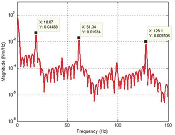
11 with the presence of structural damping and with the presence of structural damping in addition to drag moment damping in both time and frequency domain respectively. Fig. 3. Bang-bang input torque To investigate the accuracy of the FEM simulation in characterizing the behavior of the system, the algorithm was implemented on the basis of varying the number of the element from 1 to 25. Number of elements determines the accuracy of analyses and by increasing the numbers of elements, the system resonance frequencies converge to more accurate values [11]. Resonant frequencies of the system were obtained by transforming the time domain representation of the system into the frequency domain using FFT analysis. The work carried out to show the relation between the resonance modes of the system and the number of element used is summarized in Table 2. It is noted from Table 2 that the number of resonance modes identified increases with an increasing number of elements. A satisfactory dynamic behavior of a flexible manipulator, up to the second mode, could be achieved with one element. Further modes of the system are obtained with increasing the number of elements.the resonance frequency corresponding to the first mode of vibration of the system converges to the reasonably steady value with the algorithm using 2 element or more, for the second mode of vibration with 8 element and for the third mode of vibration 10 element or more. Table 2. Resonance modes of the system in relation to the number of element used Number of element Mode 1 (Hz) Mode 2 (Hz) Mode 3 (Hz) By increasing the number of elements, the system resonance frequencies converge to more accurate values, but, execution times will be high. This is mainly due to an increase in the size of the mass, damping, stiffness and state-space matrices. Figs. 4 and 5 show the end point displacement, end point residual motion, hub angle and spectral density of hub angle of the manipulator without the presence of damping using 1 and 10 elements, respectively. It is noted that the response of the system at the end point displacement and hub angle due to the bang-bang torque input reached a steady-state levels of m and rad respectively, within 0.95 sec using one and ten elements and the system response exhibits persistent oscillation JVE INTERNATIONAL LTD. JOURNAL OF VIBROENGINEERING. NOV 2014, VOLUME 16, ISSUE 7. ISSN


12 a) End-point displacement b) End-point residual c) Hub angle d) Spectral density of hub angle Fig. 4. Simulated response of the flexible manipulator without damping; Number of elements = 1 a) End-point displacement b) End-point residual c) Hub angle d) Spectral density of hub angle Fig. 5. Simulated response of the flexible manipulator without damping; Number of elements = 10 JVE INTERNATIONAL LTD. JOURNAL OF VIBROENGINEERING. NOV 2014, VOLUME 16, ISSUE 7. ISSN
13 a) End-point displacement b) End-point residual c) Hub angle d) Spectral density of hub angle Fig. 6. Simulated response of the flexible manipulator with structural damping; Number of elements =1 a) End-point displacement b) End-point residual c) Hub angle d) Spectral density of hub angle Fig. 7. Simulated response of the flexible manipulator with structural damping; Number of elements = JVE INTERNATIONAL LTD. JOURNAL OF VIBROENGINEERING. NOV 2014, VOLUME 16, ISSUE 7. ISSN
 End-point displacement b) End-point residual c) Hub angle d) Spectral density of hub")
14 a) End-point displacement b) End-point residual c) Hub angle d) Spectral density of hub angle Fig. 8. Simulated response of the flexible manipulator with structural and drag torque damping; Number of elements = 1 a) End-point displacement b) End-point residual c) Hub angle d) Spectral density of hub angle Fig. 9. Simulated response of the flexible manipulator with structural and drag torque damping; Number of elements = 10 JVE INTERNATIONAL LTD. JOURNAL OF VIBROENGINEERING. NOV 2014, VOLUME 16, ISSUE 7. ISSN
15 For the dynamic behavior of the system in the presence of structural damping, the damping ratios were assumed as and 0.01 for vibration modes 1 and 2 respectively. Using Hz and Hz as the first two resonance frequencies, and in Eq. (27) can be obtained as and respectively. Figs. 6 and 7 show the dynamic behavior of the system in the presence of structural damping with 1 and 10 elements respectively. It is noted from Fig. 7 that the damping has not affected the resonance frequencies of the system, but has resulted in considerable attenuation in the system response amplitude. Analyzing the system time response, it is noted that the hub angle, end point displacement and end point residual motion of the system converged to zero within 1.2 sec. In fluid dynamics, the drag coefficient (cd) is a dimensionless quantity that is used to quantify the drag or resistance of an object in a fluid environment, such as air or water. In this study, the drag coefficient was assumed as 1.2 to investigate the dynamic behavior of the system in the presence of structural damping and drag torque. Fig. 8 and 9 show the end point displacement, end point residual motion, hub angle and spectral density of hub angle of the manipulator with the presence of structural damping and drag torque using 1 and 10 elements, respectively. It is noted that the damping has reduce the oscillation in the system response. It is also evidenced from the spectral densities of the system response of Fig. 9, that the damping has not affected the resonance frequencies of vibration of the system. However, with damping, the level of vibration reduces as expected. To show the effects of the in-line forces on an underwater flexible single-link manipulator system model, the algorithm was compared with the land flexible single-link manipulator model. A bang-bang torque input with an amplitude ±0.3 Nm was applied at the hub of both underwater and land manipulator as shown in Fig. 3, the responses of the underwater and land flexible manipulator at the hub angle, for five elements, are monitored for duration of 1.3 second with sampling time of 1 msec and recorded as shown in Fig. 10 and Fig. 11 in time domain respectively. It can be noted that the resulted angle for an underwater manipulator was (0.763 rad) and the resulted angle for land manipulator (6.23 rad). That mean, the in-line forces on an underwater single-link manipulator are much larger than the land single-link manipulator. In other word, the torque required for the motion in water is much larger than in air to cope the effect of the in-line forces on an underwater manipulator. Fig. 10. Hub angle response of underwater manipulator Fig. 11. Hub angle response of land manipulator 4. Conclusions Theoretical investigation into the dynamic characterization of an underwater flexible single-link manipulator system has been presented. A dynamic model of an underwater manipulator has been developed using FEM based on Lagrangian approach. The performance and accuracy of the algorithm have been studied on the basis of varying the number of the element from 1 to 25. It has been demonstrated that by increasing the number of elements, better accuracy 3634 JVE INTERNATIONAL LTD. JOURNAL OF VIBROENGINEERING. NOV 2014, VOLUME 16, ISSUE 7. ISSN
16 in the characterization of the system is achieved but, at the expense of higher execution times. Effects of damping on the system due to structural damping and drag moment damping have been addressed. It is noted that the damping has not affected the resonance frequencies of the system, but has resulted in considerable attenuation in the system response amplitude. Moreover, the effects of the in-line forces on the underwater manipulator were compared with the land flexible manipulator. It has been demonstrated that the in-line forces on the underwater manipulator are much larger than the land manipulator. This study represent the base for further investigations into the application of the modeling approach considered to underwater multilink flexible manipulators and the computational requirements of complex systems of this nature. Moreover, this study can be extended to include the effect of the hub inertia and payload. This simulation platform forms the basis to implement different control structures before online control can be implemented. Acknowledgements The authors would like to express their gratitude to Minister of Education Malaysia (MOE) and Universiti Teknologi Malaysia (UTM) for funding and providing facilities to conduct this research. This research is supported using FRGS Vote No. 4F395 and UTM Research University grant, Vote No. 05H71. References [1] Gümüşel L., Özmen N. G. Modelling and control of manipulators with flexible links working on land and underwater environments. Robotica, Vol. 29, 2011, p [2] Suboh S. M., Rahman I. A., Arshad M. R., Mahyuddin M. N. Modeling and Control of 2-DOF Underwater Planar Manipulator. Indian Journal of Marine Sciences, Vol. 38, Issue 3, 2009, p [3] Darus I. Z. M., Al-Khafaji A. A. M. Nonparametric modelling of a rectangular flexible plate structure. International Journal of Engineering Application of Artificial Intelligence, Vol. 25, 2012, p [4] Guo P., Anvar A., Tan K. M. Intelligent submersible manipulator-robot, design, modeling, simulation and motion optimization for maritime robotic research. 20th International Congress on Modelling and Simulation, Adelaide, Australia, [5] Gaultier P. E., Cleghorn W. L. Modeling of flexible manipulator dynamics: a literature survey. Proceedings of First National Applied Mechanism and Robot Conference, Cincinnati, 1989, p [6] Benosman M., LeVey G. Control of flexible manipulators: A survey. Robotica, Vol. 22, p , [7] Dwivedy S. K., Eberhard P. Dynamic analysis of flexible manipulators, a literature review. Mechanism and Machine Theory, Vol. 41, p , [8] Tokhi M. O., Azad A. K. M. Real time finite difference simulation of a single-link flexible manipulator incorporating hub inertia and payload. Journal of Systems and Control Engineering Vol. 209, Issue I1, p , [9] Rao S. S. The finite element method in engineering. Fourth Edition, Butterworth Heinemann, [10] Tokhi M. O., Azad A. K. M. Flexible Robot Manipulators Modelling, Simulation and Control. The Institution of Engineering and Technology, London, United Kingdom, [11] Tokhi M. O., Mohamed Z., Shaheed H. M. Dynamic characterisation of a flexible manipulator system. Robotica, Vol. 19, Issue 5, 2001, p [12] Tokhi M. O., Mohamed Z., Azad A. K. M. Finite difference and finite element approaches to dynamic modelling of a flexible manipulator. Proceedings of the Institution of Mechanical Engineers, Part I: Journal of Systems and Control Engineering, Vol. 211, 1997, p [13] Rahman I. A., Suboh S. M., Arshad M. R. Theory and design issues of underwater manipulator. International Conference on Control, Instrumentation and Mechatronics Engineering, Malaysia, [14] Li R., Anvar A. P., Anvar A. M., Lu T. Dynamic modeling of underwater manipulator and its simulation. World Academy of Science, Engineering and Technology, Vol. 72, 2012, p JVE INTERNATIONAL LTD. JOURNAL OF VIBROENGINEERING. NOV 2014, VOLUME 16, ISSUE 7. ISSN
![[15] Mclain T. W. Modeling of underwater manipulator hydrodynamics with application to the coordinated control of an arm/vehicle system. Ph.D.](/docs-images/92/110995207/images/17-0.jpg "thesis, Department of Mechanical Engineering and the Committee on Graduate Studies of Stanford University, 1995. [16] Lionel L.")
![Underwater Robots Part II: Existing Solutions and Open Issues, Mobile Robots: towards New Applications. InTech, 2006. [17] Rustad A. M. Modeling and control of top tensioned risers. Ph.D.](/docs-images/92/110995207/images/17-1.jpg "thesis, Department of Marine Technology, Norwegian University of Science and Technology, 2007. [18] Zhu Z. H., Meguid S. A. Modeling and simulation of aerial refueling by finite element method.")
17 [15] Mclain T. W. Modeling of underwater manipulator hydrodynamics with application to the coordinated control of an arm/vehicle system. Ph.D. thesis, Department of Mechanical Engineering and the Committee on Graduate Studies of Stanford University, [16] Lionel L. Underwater Robots Part II: Existing Solutions and Open Issues, Mobile Robots: towards New Applications. InTech, [17] Rustad A. M. Modeling and control of top tensioned risers. Ph.D. thesis, Department of Marine Technology, Norwegian University of Science and Technology, [18] Zhu Z. H., Meguid S. A. Modeling and simulation of aerial refueling by finite element method. International Journal of Solids and Structures, Vol. 44, 2007, p [19] Zhang Z., Zhao X., Li Y., Zhao S. Review on the type of damping and its common models in civil engineering. 9th International Conference on Fracture and Strength of Solids, Jeju, Korea, Ali A. M. Al-khafaji was born in Baghdad, Iraq, in July 3st, He received his Bachelor degree in Mechanical Engineering from the University of Technology-Baghdad, Iraq in the year 1999 and completed his Master s Degree in Mechanical Engineering from the University Teknologi Malaysia (UTM), Malaysia in the year His field of research is in control engineering and currently extending his knowledge by undergoing Ph.D. studies on Active Vibration Control in UTM. Intan Z. M. Darus was born in Melaka, Malaysia, in September 16th, She received her First Class B.Eng. (Hons.) degree in Mechanical Engineering from the University of Wales College Cardiff, Wales, United Kingdom in 1998 and later her Ph.D. in Automatic Control and Systems Engineering from the University of Sheffield, United Kingdom in Currently, she is an Associate Professor in the Department of System Dynamics and Control, Faculty of Mechanical Engineering, University Teknologi Malaysia. Her current research interests are active vibration control, modeling and simulation of dynamical system, soft computing and artificial intelligent techniques for system identification and control JVE INTERNATIONAL LTD. JOURNAL OF VIBROENGINEERING. NOV 2014, VOLUME 16, ISSUE 7. ISSN
Shape Optimization of Revolute Single Link Flexible Robotic Manipulator for Vibration Suppression
 15 th National Conference on Machines and Mechanisms NaCoMM011-157 Shape Optimization of Revolute Single Link Flexible Robotic Manipulator for Vibration Suppression Sachindra Mahto Abstract In this work,
1820. Selection of torsional vibration damper based on the results of simulation
 8. Selection of torsional vibration damper based on the results of simulation Tomasz Matyja, Bogusław Łazarz Silesian University of Technology, Faculty of Transport, Gliwice, Poland Corresponding author
1859. Forced transverse vibration analysis of a Rayleigh double-beam system with a Pasternak middle layer subjected to compressive axial load
 1859. Forced transverse vibration analysis of a Rayleigh double-beam system with a Pasternak middle layer subjected to compressive axial load Nader Mohammadi 1, Mehrdad Nasirshoaibi 2 Department of Mechanical
1439. Numerical simulation of the magnetic field and electromagnetic vibration analysis of the AC permanent-magnet synchronous motor
 1439. Numerical simulation of the magnetic field and electromagnetic vibration analysis of the AC permanent-magnet synchronous motor Bai-zhou Li 1, Yu Wang 2, Qi-chang Zhang 3 1, 2, 3 School of Mechanical
1410. Fuzzy-PID controller on ANFIS, NN-NARX and NN-NAR system identification models for cylinder vortex induced vibration
 1410. Fuzzy-PID controller on ANFIS, NN-NARX and NN-NAR system identification models for cylinder vortex induced vibration Mohammed Jawad Mohammed 1, Intan Z. Mat Darus 2 1, 2 Department of Applied Mechanics,
Study of the influence of the resonance changer on the longitudinal vibration of marine propulsion shafting system
 Study of the influence of the resonance changer on the longitudinal vibration of marine propulsion shafting system Zhengmin Li 1, Lin He 2, Hanguo Cui 3, Jiangyang He 4, Wei Xu 5 1, 2, 4, 5 Institute of
 University of California at Berkeley Structural Engineering Mechanics & Materials Department of Civil & Environmental Engineering Spring 2012 Student name : Doctoral Preliminary Examination in Dynamics
2040. Damage modeling and simulation of vibrating pipe with part-through circumferential crack
 24. Damage modeling and simulation of vibrating pipe with part-through circumferential crack Zhihong Yu 1, Laibin Zhang 2, Jinqiu Hu 3, Jiashun Hu 4 1, 2, 3 College of Mechanical and Transportation Engineering,
Structural Dynamics Lecture Eleven: Dynamic Response of MDOF Systems: (Chapter 11) By: H. Ahmadian
 By: H. Ahmadian") Structural Dynamics Lecture Eleven: Dynamic Response of MDOF Systems: (Chapter 11) By: H. Ahmadian ahmadian@iust.ac.ir Dynamic Response of MDOF Systems: Mode-Superposition Method Mode-Superposition Method:
Structural Dynamics Lecture Eleven: Dynamic Response of MDOF Systems: (Chapter 11) By: H. Ahmadian ahmadian@iust.ac.ir Dynamic Response of MDOF Systems: Mode-Superposition Method Mode-Superposition Method:
Effect of Angular movement of Lifting Arm on Natural Frequency of Container Lifting Mechanism using Finite Element Modal Analysis
 Effect of Angular movement of Lifting Arm on Natural Frequency of Container Lifting Mechanism using Finite Element Modal Analysis Khodu M Dhameliya, 2 Utpal V Shah, 3 Dhaval Makwana, 4 Mansi Yadav, 5 Ishankumar
Structural Dynamics A Graduate Course in Aerospace Engineering
 Structural Dynamics A Graduate Course in Aerospace Engineering By: H. Ahmadian ahmadian@iust.ac.ir The Science and Art of Structural Dynamics What do all the followings have in common? > A sport-utility
DREDGING DYNAMICS AND VIBRATION MEASURES
 DREDGING DYNAMICS AND VIBRATION MEASURES C R Barik, K Vijayan, Department of Ocean Engineering and Naval Architecture, IIT Kharagpur, India ABSTRACT The demands for dredging have found a profound increase
Modeling and Control of 2-DOF Underwater Planar Manipulator
 Modeling and Control of 2-DOF Underwater Planar Manipulator Surina Mat Suboh, Irfan Abd Rahman, Mohd Rizal Arshad, Muhammad Nasiruddin Mahyuddin USM Robotics Research Group (URRG), School of Electrical
2044. Dynamics analysis for the clamping mechanisms of a rotary inchworm piezoelectric motor
 2044. Dynamics analysis for the clamping mechanisms of a rotary inchworm piezoelectric motor Yongfei Gu 1, Jichun Xing 2 1, 2 School of Mechanical Engineering, Yanshan University, Qinhuangdao, China 1
Structural Dynamics Lecture 4. Outline of Lecture 4. Multi-Degree-of-Freedom Systems. Formulation of Equations of Motions. Undamped Eigenvibrations.
 Outline of Multi-Degree-of-Freedom Systems Formulation of Equations of Motions. Newton s 2 nd Law Applied to Free Masses. D Alembert s Principle. Basic Equations of Motion for Forced Vibrations of Linear
Dynamics of assembled structures of rotor systems of aviation gas turbine engines of type two-rotor
 Dynamics of assembled structures of rotor systems of aviation gas turbine engines of type two-rotor Anatoly А. Pykhalov 1, Mikhail А. Dudaev 2, Mikhail Ye. Kolotnikov 3, Paul V. Makarov 4 1 Irkutsk State
Modelling of lateral-torsional vibrations of the crank system with a damper of vibrations
 Modelling of lateral-torsional vibrations of the crank system with a damper of vibrations Bogumil Chiliński 1, Maciej Zawisza 2 Warsaw University of Technology, Institute of Machine Design Fundamentals,
International Journal of Scientific & Engineering Research, Volume 5, Issue 7, July-2014 ISSN
 ISSN 2229-5518 692 In literature, finite element formulation uses beam element or plate element for structural modelling which has a limitation on transverse displacement. Atkinson and Manrique [1] studied
0000. Finite element modeling of a wind turbine blade
 ArticleID: 16033; Draft date: 2015-07-27 0000. Finite element modeling of a wind turbine blade Mohammad Sheibani 1, Ali Akbar Akbari 2 Department of Mechanical Engineering, Ferdowsi University of Mashhad,
Student name: This is a closed book examination. You are allowed 1 sheet of 8.5 x 11 paper with notes.
 13.012 Marine Hydrodynamics for Ocean Engineers Fall 2004 Quiz #2 Student name: This is a closed book examination. You are allowed 1 sheet of 8.5 x 11 paper with notes. For the problems in Section A, fill
2108. Free vibration properties of rotate vector reducer
 2108. Free vibration properties of rotate vector reducer Chuan Chen 1, Yuhu Yang 2 School of Mechanical Engineering, Tianjin University, Tianjin, 300072, P. R. China 1 Corresponding author E-mail: 1 chenchuan1985728@126.com,
Name: Fall 2014 CLOSED BOOK
 Name: Fall 2014 1. Rod AB with weight W = 40 lb is pinned at A to a vertical axle which rotates with constant angular velocity ω =15 rad/s. The rod position is maintained by a horizontal wire BC. Determine
Structural Dynamics. Spring mass system. The spring force is given by and F(t) is the driving force. Start by applying Newton s second law (F=ma).
 is the driving force. Start by applying Newton s second law (F=ma).") Structural Dynamics Spring mass system. The spring force is given by and F(t) is the driving force. Start by applying Newton s second law (F=ma). We will now look at free vibrations. Considering the free
Structural Dynamics Spring mass system. The spring force is given by and F(t) is the driving force. Start by applying Newton s second law (F=ma). We will now look at free vibrations. Considering the free
THE subject of the analysis is system composed by
 MECHANICAL VIBRATION ASSIGNEMENT 1 On 3 DOF system identification Diego Zenari, 182160, M.Sc Mechatronics engineering Abstract The present investigation carries out several analyses on a 3-DOF system.
Trajectory Tracking of a Near-Surface Torpedo using Numerical Methods
 ISSN (Print) : 2347-671 An ISO 3297: 27 Certified Organization Vol.4, Special Issue 12, September 215 Trajectory Tracking of a Near-Surface Torpedo using Numerical Methods Anties K. Martin, Anubhav C.A.,
Numerical simulation of the coil spring and investigation the impact of tension and compression to the spring natural frequencies
 Numerical simulation of the coil spring and investigation the impact of tension and compression to the spring natural frequencies F. D. Sorokin 1, Zhou Su 2 Bauman Moscow State Technical University, Moscow,
DYNAMIC CHARACTERISTICS OF OFFSHORE TENSION LEG PLATFORMS UNDER HYDRODYNAMIC FORCES
 International Journal of Civil Engineering (IJCE) ISSN(P): 2278-9987; ISSN(E): 2278-9995 Vol. 3, Issue 1, Jan 214, 7-16 IASET DYNAMIC CHARACTERISTICS OF OFFSHORE TENSION LEG PLATFORMS UNDER HYDRODYNAMIC
ANALYSIS OF HIGHRISE BUILDING STRUCTURE WITH SETBACK SUBJECT TO EARTHQUAKE GROUND MOTIONS
 ANALYSIS OF HIGHRISE BUILDING SRUCURE WIH SEBACK SUBJEC O EARHQUAKE GROUND MOIONS 157 Xiaojun ZHANG 1 And John L MEEK SUMMARY he earthquake response behaviour of unframed highrise buildings with setbacks
Model Reference Adaptive Control of Underwater Robotic Vehicle in Plane Motion
 Proceedings of the 11th WSEAS International Conference on SSTEMS Agios ikolaos Crete Island Greece July 23-25 27 38 Model Reference Adaptive Control of Underwater Robotic Vehicle in Plane Motion j.garus@amw.gdynia.pl
Study on Structural Deflection in Attitude Maneuvers of Flexible Satellite Equipped with Fuel-Efficient Input Shaper
 -Science and Engineering-, Vol.4 October 3, 15 Study on Structural Deflection in Attitude Maneuvers of Flexible Satellite Equipped with Fuel-Efficient nput Shaper Setyamartana Parman a,* a) Department
Dynamics and Control of the GyroPTO Wave Energy Point Absorber under Sea Waves
 Available online at www.sciencedirect.com ScienceDirect Procedia Engineering 99 (7) 88 8 X International Conference on Structural Dynamics, EURODYN 7 Dynamics and Control of the GyroPTO Wave Energy Point
GAME PHYSICS (INFOMGP) FINAL EXAM
 FINAL EXAM") GAME PHYSICS (INFOMGP) FINAL EXAM 15/JUN/ 016 LECTURER: AMIR VAXMAN Student name: Student number: This exam is 3 hours long and consists of 5 exercises. The points add up to 100. Answer only in English.
GAME PHYSICS (INFOMGP) FINAL EXAM 15/JUN/ 016 LECTURER: AMIR VAXMAN Student name: Student number: This exam is 3 hours long and consists of 5 exercises. The points add up to 100. Answer only in English.
VIBRATION ENERGY FLOW IN WELDED CONNECTION OF PLATES. 1. Introduction
 ARCHIVES OF ACOUSTICS 31, 4 (Supplement), 53 58 (2006) VIBRATION ENERGY FLOW IN WELDED CONNECTION OF PLATES J. CIEŚLIK, W. BOCHNIAK AGH University of Science and Technology Department of Robotics and Mechatronics
Frequency response analysis of the gear box in a lathe machine using transfer functions
 International Journal of Scientific and Research Publications, Volume 4, Issue 11, November 2014 1 Frequency response analysis of the gear box in a lathe machine using transfer functions V Suma Priya 1a,
D : SOLID MECHANICS. Q. 1 Q. 9 carry one mark each.
 GTE 2016 Q. 1 Q. 9 carry one mark each. D : SOLID MECHNICS Q.1 single degree of freedom vibrating system has mass of 5 kg, stiffness of 500 N/m and damping coefficient of 100 N-s/m. To make the system
IDENTIFICATION OF FRICTION ENERGY DISSIPATION USING FREE VIBRATION VELOCITY: MEASUREMENT AND MODELING
 IDENTIFICATION OF FRICTION ENERGY DISSIPATION USING FREE VIBRATION VELOCITY: MEASUREMENT AND MODELING Christoph A. Kossack, Tony L. Schmitz, and John C. Ziegert Department of Mechanical Engineering and
Preliminary Examination - Dynamics
 Name: University of California, Berkeley Fall Semester, 2018 Problem 1 (30% weight) Preliminary Examination - Dynamics An undamped SDOF system with mass m and stiffness k is initially at rest and is then
1330. Comparative study of model updating methods using frequency response function data
 1330. Comparative study of model updating methods using frequency response function data Dong Jiang 1, Peng Zhang 2, Qingguo Fei 3, Shaoqing Wu 4 Jiangsu Key Laboratory of Engineering Mechanics, Nanjing,
Influence of electromagnetic stiffness on coupled micro vibrations generated by solar array drive assembly
 Influence of electromagnetic stiffness on coupled micro vibrations generated by solar array drive assembly Mariyam Sattar 1, Cheng Wei 2, Awais Jalali 3 1, 2 Beihang University of Aeronautics and Astronautics,
STRUCTURAL DYNAMICS BASICS:
 BASICS: STRUCTURAL DYNAMICS Real-life structures are subjected to loads which vary with time Except self weight of the structure, all other loads vary with time In many cases, this variation of the load
AA 242B/ ME 242B: Mechanical Vibrations (Spring 2016)
") AA 242B/ ME 242B: Mechanical Vibrations (Spring 2016) Homework #2 Due April 17, 2016 This homework focuses on developing a simplified analytical model of the longitudinal dynamics of an aircraft during
AA 242B/ ME 242B: Mechanical Vibrations (Spring 2016) Homework #2 Due April 17, 2016 This homework focuses on developing a simplified analytical model of the longitudinal dynamics of an aircraft during
LANMARK UNIVERSITY OMU-ARAN, KWARA STATE DEPARTMENT OF MECHANICAL ENGINEERING COURSE: MECHANICS OF MACHINE (MCE 322). LECTURER: ENGR.
. LECTURER: ENGR.") LANMARK UNIVERSITY OMU-ARAN, KWARA STATE DEPARTMENT OF MECHANICAL ENGINEERING COURSE: MECHANICS OF MACHINE (MCE 322). LECTURER: ENGR. IBIKUNLE ROTIMI ADEDAYO SIMPLE HARMONIC MOTION. Introduction Consider
LANMARK UNIVERSITY OMU-ARAN, KWARA STATE DEPARTMENT OF MECHANICAL ENGINEERING COURSE: MECHANICS OF MACHINE (MCE 322). LECTURER: ENGR. IBIKUNLE ROTIMI ADEDAYO SIMPLE HARMONIC MOTION. Introduction Consider
UNITS AND DEFINITIONS RELATED TO BIOMECHANICAL AND ELECTROMYOGRAPHICAL MEASUREMENTS
 APPENDIX B UNITS AND DEFINITIONS RELATED TO BIOMECHANICAL AND ELECTROMYOGRAPHICAL MEASUREMENTS All units used are SI (Système International d Unités). The system is based on seven well-defined base units
Mathematical modeling of three-layer beam hydroelastic oscillations
 Mathematical modeling of three-layer beam hydroelastic oscillations L. I. Mogilevich 1, V. S. Popov, A. A. Popova 3, A. V. Christoforova 4, E. V. Popova 5 1,, 3 Yuri Gagarin State Technical University
NONLINEAR STRUCTURAL DYNAMICS USING FE METHODS
 NONLINEAR STRUCTURAL DYNAMICS USING FE METHODS Nonlinear Structural Dynamics Using FE Methods emphasizes fundamental mechanics principles and outlines a modern approach to understanding structural dynamics.
Computational Simulation of Dynamic Response of Vehicle Tatra T815 and the Ground
 IOP Conference Series: Earth and Environmental Science PAPER OPEN ACCESS Computational Simulation of Dynamic Response of Vehicle Tatra T815 and the Ground To cite this article: Jozef Vlek and Veronika
Design and Comparison of Different Controllers to Stabilize a Rotary Inverted Pendulum
 ISSN (Online): 347-3878, Impact Factor (5): 3.79 Design and Comparison of Different Controllers to Stabilize a Rotary Inverted Pendulum Kambhampati Tejaswi, Alluri Amarendra, Ganta Ramesh 3 M.Tech, Department
Dynamic Model of a Badminton Stroke
 ISEA 28 CONFERENCE Dynamic Model of a Badminton Stroke M. Kwan* and J. Rasmussen Department of Mechanical Engineering, Aalborg University, 922 Aalborg East, Denmark Phone: +45 994 9317 / Fax: +45 9815
This equation of motion may be solved either by differential equation method or by graphical method as discussed below:
 2.15. Frequency of Under Damped Forced Vibrations Consider a system consisting of spring, mass and damper as shown in Fig. 22. Let the system is acted upon by an external periodic (i.e. simple harmonic)
1653. Effect of cut-out on modal properties of edge cracked temperature-dependent functionally graded plates
 1653. Effect of cut-out on modal properties of edge cracked temperature-dependent functionally graded plates A. Shahrjerdi 1, T. Ezzati 2 1 Department of Mechanical Engineering, Malayer University, Malayer
C. points X and Y only. D. points O, X and Y only. (Total 1 mark)
") Grade 11 Physics -- Homework 16 -- Answers on a separate sheet of paper, please 1. A cart, connected to two identical springs, is oscillating with simple harmonic motion between two points X and Y that
Grade 11 Physics -- Homework 16 -- Answers on a separate sheet of paper, please 1. A cart, connected to two identical springs, is oscillating with simple harmonic motion between two points X and Y that
EQUIVALENT SINGLE-DEGREE-OF-FREEDOM SYSTEM AND FREE VIBRATION
 1 EQUIVALENT SINGLE-DEGREE-OF-FREEDOM SYSTEM AND FREE VIBRATION The course on Mechanical Vibration is an important part of the Mechanical Engineering undergraduate curriculum. It is necessary for the development
Table of Contents. Preface... 13
 Table of Contents Preface... 13 Chapter 1. Vibrations of Continuous Elastic Solid Media... 17 1.1. Objective of the chapter... 17 1.2. Equations of motion and boundary conditions of continuous media...
TOPIC E: OSCILLATIONS EXAMPLES SPRING Q1. Find general solutions for the following differential equations:
 TOPIC E: OSCILLATIONS EXAMPLES SPRING 2019 Mathematics of Oscillating Systems Q1. Find general solutions for the following differential equations: Undamped Free Vibration Q2. A 4 g mass is suspended by
A new cantilever beam-rigid-body MEMS gyroscope: mathematical model and linear dynamics
 Proceedings of the International Conference on Mechanical Engineering and Mechatronics Toronto, Ontario, Canada, August 8-10 2013 Paper No. XXX (The number assigned by the OpenConf System) A new cantilever
CFD ANALYSIS FOR A REMOTELY OPERATED VEHICLE IN HORIZONTAL PLAN
 Mechanical Testing and Diagnosis ISSN 47 9635, 018 (VIII), Volume 1, pp. 5-10 CFD ANALYSIS FOR A REMOTELY OPERATED VEHICLE IN HORIZONTAL PLAN Andra Teodora NEDELCU 1)*, Catalin FAITARB, Mihail Lucian DUMITRACHE
PROJECT 1 DYNAMICS OF MACHINES 41514
 PROJECT DYNAMICS OF MACHINES 454 Theoretical and Experimental Modal Analysis and Validation of Mathematical Models in Multibody Dynamics Ilmar Ferreira Santos, Professor Dr.-Ing., Dr.Techn., Livre-Docente
The basic principle to be used in mechanical systems to derive a mathematical model is Newton s law,
 Chapter. DYNAMIC MODELING Understanding the nature of the process to be controlled is a central issue for a control engineer. Thus the engineer must construct a model of the process with whatever information
Estimation of Rotational FRFs via Cancellation Methods
 Estimation of Rotational FRFs via Cancellation Methods Nomenclature ij ( l, k ) ij M. Reza shory, Semnan university, Iran Email: mashoori@semnan.ac.ir exact ccelerance measured accelerance when two mechanical
PHY 001 (Physics I) Lecture 7
 Lecture 7") PHY 001 (Physics I) Instructor: Dr. Mohamed Fouad Salem mohamed.salem@gmail.com Textbook University Physics, 12 th edition, Young and Freedman Course Material Website http://meryesk.wordpress.com/phy001/
PHY 001 (Physics I) Instructor: Dr. Mohamed Fouad Salem mohamed.salem@gmail.com Textbook University Physics, 12 th edition, Young and Freedman Course Material Website http://meryesk.wordpress.com/phy001/
PROPELLER INDUCED STRUCTURAL VIBRATION THROUGH THE THRUST BEARING
 PROPELLER INDUCED TRUCTURAL VIBRATION THROUGH THE THRUT BEARING Jie Pan, Nabil Farag, Terry Lin and Ross Juniper* DEPARTMENT OF MECHANICAL AND MATERIAL ENGINEERING THE UNIVERITY OF WETERN AUTRALIA 35 TIRLING
Dynamic behavior of turbine foundation considering full interaction among facility, structure and soil
 Dynamic behavior of turbine foundation considering full interaction among facility, structure and soil Fang Ming Scholl of Civil Engineering, Harbin Institute of Technology, China Wang Tao Institute of
available online at CONTROL OF THE DOUBLE INVERTED PENDULUM ON A CART USING THE NATURAL MOTION
 Acta Polytechnica 3(6):883 889 3 Czech Technical University in Prague 3 doi:.43/ap.3.3.883 available online at http://ojs.cvut.cz/ojs/index.php/ap CONTROL OF THE DOUBLE INVERTED PENDULUM ON A CART USING
Integration simulation method concerning speed control of ultrasonic motor
 Integration simulation method concerning speed control of ultrasonic motor R Miyauchi 1, B Yue 2, N Matsunaga 1 and S Ishizuka 1 1 Cybernet Systems Co., Ltd. 3 Kanda-neribeicho,Chiyoda-ku, Tokyo,101-0022,Japan
on the figure. Someone has suggested that, in terms of the degrees of freedom x1 and M. Note that if you think the given 1.2
 1) A two-story building frame is shown below. The mass of the frame is assumed to be lumped at the floor levels and the floor slabs are considered rigid. The floor masses and the story stiffnesses are
Analytical Solution for a Fluid-Structure Interaction Problem in Comparison with Finite Element Solution
 Analytical Solution for a Fluid-Structure Interaction Problem in Comparison with Finite Element Solution Amirhossein Keivani & Ahmad Shooshtari Ferdowsi University of Mashhad, Mashhad, Iran. Ahmad Aftabi
Dynamics of Machinery
 Dynamics of Machinery Two Mark Questions & Answers Varun B Page 1 Force Analysis 1. Define inertia force. Inertia force is an imaginary force, which when acts upon a rigid body, brings it to an equilibrium
Stockbridge-Type Damper Effectiveness Evaluation: Part II The Influence of the Impedance Matrix Terms on the Energy Dissipated
 1470 IEEE TRANSACTIONS ON POWER DELIVERY, VOL. 18, NO. 4, OCTOBER 2003 Stockbridge-Type Damper Effectiveness Evaluation: Part II The Influence of the Impedance Matrix Terms on the Energy Dissipated Giorgio
Effect of Liquid Viscosity on Sloshing in A Rectangular Tank
 International Journal of Research in Engineering and Science (IJRES) ISSN (Online): 2320-9364, ISSN (Print): 2320-9356 Volume 5 Issue 8 ǁ August. 2017 ǁ PP. 32-39 Effect of Liquid Viscosity on Sloshing
Simple Modeling and Modal Analysis of Reciprocating Compressor Crankshaft System
 Purdue University Purdue e-pubs International Compressor Engineering Conference School of Mechanical Engineering 2010 Simple Modeling and Modal Analysis of Reciprocating Compressor Crankshaft System Binyan
COPYRIGHTED MATERIAL. Index
 Index A Admissible function, 163 Amplification factor, 36 Amplitude, 1, 22 Amplitude-modulated carrier, 630 Amplitude ratio, 36 Antinodes, 612 Approximate analytical methods, 647 Assumed modes method,
ELASTODYNAMIC ANALYSIS OF FOUR BAR MECHANISM USING MATLAB AND ANSYS WB
 International Journal of Mechanical and Production Engineering Research and Development (IJMPERD ) ISSN 49-689 Vol., Issue Sep 1 76-8 TJPRC Pvt. td., EASTODYNAMIC ANAYSIS OF FOUR BAR MECHANISM USING MATAB
Deflections and Strains in Cracked Shafts due to Rotating Loads: A Numerical and Experimental Analysis
 Rotating Machinery, 10(4): 283 291, 2004 Copyright c Taylor & Francis Inc. ISSN: 1023-621X print / 1542-3034 online DOI: 10.1080/10236210490447728 Deflections and Strains in Cracked Shafts due to Rotating
Finite Element Analysis Prof. Dr. B. N. Rao Department of Civil Engineering Indian Institute of Technology, Madras. Module - 01 Lecture - 11
 Finite Element Analysis Prof. Dr. B. N. Rao Department of Civil Engineering Indian Institute of Technology, Madras Module - 01 Lecture - 11 Last class, what we did is, we looked at a method called superposition
T1 T e c h n i c a l S e c t i o n
 1.5 Principles of Noise Reduction A good vibration isolation system is reducing vibration transmission through structures and thus, radiation of these vibration into air, thereby reducing noise. There
ANALYSIS AND IDENTIFICATION IN ROTOR-BEARING SYSTEMS
 ANALYSIS AND IDENTIFICATION IN ROTOR-BEARING SYSTEMS A Lecture Notes Developed under the Curriculum Development Scheme of Quality Improvement Programme at IIT Guwahati Sponsored by All India Council of
Advanced Vibrations. Elements of Analytical Dynamics. By: H. Ahmadian Lecture One
 Advanced Vibrations Lecture One Elements of Analytical Dynamics By: H. Ahmadian ahmadian@iust.ac.ir Elements of Analytical Dynamics Newton's laws were formulated for a single particle Can be extended to
Lecture 6 mechanical system modeling equivalent mass gears
 M2794.25 Mechanical System Analysis 기계시스템해석 lecture 6,7,8 Dongjun Lee ( 이동준 ) Department of Mechanical & Aerospace Engineering Seoul National University Dongjun Lee Lecture 6 mechanical system modeling
3 Mathematical modeling of the torsional dynamics of a drill string
 3 Mathematical modeling of the torsional dynamics of a drill string 3.1 Introduction Many works about torsional vibrations on drilling systems [1, 12, 18, 24, 41] have been published using different numerical
ScienceDirect. The Stability of a Precessing and Nutating Viscoelastic Beam with a Tip Mass
 Available online at www.sciencedirect.com ScienceDirect Procedia Engineering 144 (2016 ) 68 76 12th International Conference on Vibration Problems, ICOVP 2015 The Stability of a Precessing and Nutating
PRELIMINARY MODELLING OF A MARINE PROPULSION SYSTEM
 PRELIMINARY MODELLING OF A MARINE PROPULSION SYSTEM Andrew Youssef 1 Andrew Guzzomi 2, Jie Pan 3 and Paul Dylejko 4 1-3 School of Mechanical and Chemical Engineering UWA Australia, Perth WA 6009, Australia
The sensitivity analysis of the translation and the rotation angle of the first-order mode shape of the joints in frame structures
 The sensitivity analysis of the translation and the rotation angle of the first-order mode shape of the joints in frame structures Yi Chen Yuan 1, Lin Li 2, Hongping Zhu 3 School of Civil Engineering and
Answers to questions in each section should be tied together and handed in separately.
 EGT0 ENGINEERING TRIPOS PART IA Wednesday 4 June 014 9 to 1 Paper 1 MECHANICAL ENGINEERING Answer all questions. The approximate number of marks allocated to each part of a question is indicated in the
COMPARATIVE STUDY OF VARIOUS BEAMS UNDER DIFFERENT LOADING CONDITION USING FINITE ELEMENT METHOD
 COMPARATIVE STUDY OF VARIOUS BEAMS UNDER DIFFERENT LOADING CONDITION USING FINITE ELEMENT METHOD A THESIS SUBMITTED IN PARTIAL FULLFILLMENT OF THE REQUIREMENTS FOR THE DEGREE OF Bachelor of Technology
Q. 1 Q. 5 carry one mark each.
 General ptitude G Set-8 Q. 1 Q. 5 carry one mark each. Q.1 The chairman requested the aggrieved shareholders to him. () bare with () bore with (C) bear with (D) bare Q.2 Identify the correct spelling out
Vortex-induced vibration of a slender single-span cylinder
 Vortex-induced vibration of a slender single-span cylinder N. Oikou Delft University of Technology, the Netherlands The goal of this paper is to study the vortex-induced vibration of slender cylindrical
Pierre Bigot 2 and Luiz C. G. de Souza 3
 INTERNATIONAL JOURNAL OF SYSTEMS APPLICATIONS, ENGINEERING & DEVELOPMENT Volume 8, 2014 Investigation of the State Dependent Riccati Equation (SDRE) adaptive control advantages for controlling non-linear
DHANALAKSHMI COLLEGE OF ENGINEERING, CHENNAI DEPARTMENT OF MECHANICAL ENGINEERING ME 6603 FINITE ELEMENT ANALYSIS PART A (2 MARKS)
") DHANALAKSHMI COLLEGE OF ENGINEERING, CHENNAI DEPARTMENT OF MECHANICAL ENGINEERING ME 6603 FINITE ELEMENT ANALYSIS UNIT I : FINITE ELEMENT FORMULATION OF BOUNDARY VALUE PART A (2 MARKS) 1. Write the types
DHANALAKSHMI COLLEGE OF ENGINEERING, CHENNAI DEPARTMENT OF MECHANICAL ENGINEERING ME 6603 FINITE ELEMENT ANALYSIS UNIT I : FINITE ELEMENT FORMULATION OF BOUNDARY VALUE PART A (2 MARKS) 1. Write the types
Application of singular perturbation theory in modeling and control of flexible robot arm
 Research Article International Journal of Advanced Technology and Engineering Exploration, Vol 3(24) ISSN (Print): 2394-5443 ISSN (Online): 2394-7454 http://dx.doi.org/10.19101/ijatee.2016.324002 Application
CHAPTER 4 DESIGN AND ANALYSIS OF CANTILEVER BEAM ELECTROSTATIC ACTUATORS
 61 CHAPTER 4 DESIGN AND ANALYSIS OF CANTILEVER BEAM ELECTROSTATIC ACTUATORS 4.1 INTRODUCTION The analysis of cantilever beams of small dimensions taking into the effect of fringing fields is studied and
2032. Dynamic characteristics of pipe-soil interaction for steel catenary riser in touchdown zone
 2032. Dynamic characteristics of pipe-soil interaction for steel catenary riser in touchdown zone Yong-hong Cao 1, Yong-qiang Jing 2, Zheng-hong Guo 3 1, 2 School of Science, North University of China,
Introduction to Continuous Systems. Continuous Systems. Strings, Torsional Rods and Beams.
 Outline of Continuous Systems. Introduction to Continuous Systems. Continuous Systems. Strings, Torsional Rods and Beams. Vibrations of Flexible Strings. Torsional Vibration of Rods. Bernoulli-Euler Beams.
Effect of Tethers Tension Force in the Behavior of a Tension Leg Platform Subjected to Hydrodynamic Force Amr R. El-Gamal, Ashraf Essa, Ayman Ismail
 Vol:7, No:1, 13 Effect of Tethers Tension Force in the Behavior of a Tension Leg Platform Subjected to Hydrodynamic Force Amr R. El-Gamal, Ashraf Essa, Ayman Ismail International Science Index, Bioengineering
2028. Life estimation of the beam with normal distribution parameters and subjected to cyclic load
 2028. Life estimation of the beam with normal distribution parameters and subjected to cyclic load Changyou Li 1, Xuchu Wang 2, Wei Wang 3, Yimin Zhang 4, Song Guo 5 1, 2, 3, 4 School of Mechanical Engineering
Multibody dynamics of mechanism with secondary system
 University of Iowa Iowa Research Online Theses and Dissertations Spring 212 Multibody dynamics of mechanism with secondary system Jun Hyeak Choi University of Iowa Copyright 212 Jun Choi This thesis is
Numerical investigation on vortex-induced motion of a pivoted cylindrical body in uniform flow
 Fluid Structure Interaction VII 147 Numerical investigation on vortex-induced motion of a pivoted cylindrical body in uniform flow H. G. Sung 1, H. Baek 2, S. Hong 1 & J.-S. Choi 1 1 Maritime and Ocean
CHAPTER 14 BUCKLING ANALYSIS OF 1D AND 2D STRUCTURES
 CHAPTER 14 BUCKLING ANALYSIS OF 1D AND 2D STRUCTURES 14.1 GENERAL REMARKS In structures where dominant loading is usually static, the most common cause of the collapse is a buckling failure. Buckling may
Finite Element Analysis of Piezoelectric Cantilever
 Finite Element Analysis of Piezoelectric Cantilever Nitin N More Department of Mechanical Engineering K.L.E S College of Engineering and Technology, Belgaum, Karnataka, India. Abstract- Energy (or power)
1615. Nonlinear dynamic response analysis of a cantilever beam with a breathing crack
 65. Nonlinear dynamic response analysis of a cantilever beam with a breathing crack ShaoLin Qiu, LaiBin Zhang 2, JiaShun Hu 3, Yu Jiang 4, 2 College of Mechanical, Storage and Transportation Engineering,
A body is displaced from equilibrium. State the two conditions necessary for the body to execute simple harmonic motion
 1. Simple harmonic motion and the greenhouse effect (a) A body is displaced from equilibrium. State the two conditions necessary for the body to execute simple harmonic motion. 1. 2. (b) In a simple model