CHAPTER 2. Structural Geology. Section I. Structural Features in Sedimentary Rocks FM 5-410
|
|
|
- Dora Dixon
- 5 years ago
- Views:
Transcription
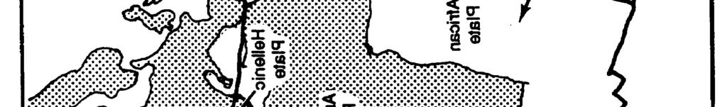
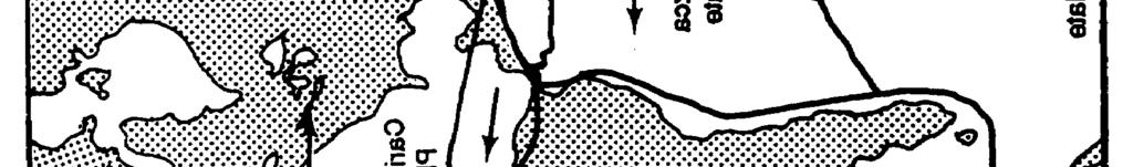
1 CHAPTER 2 Structural Geology Structural geology describes the form, pattern, origin, and internal structure of rock and soil masses. Tectonics, a closely related field, deals with structural features on a larger regional, continental, or global scale. Figure 2-1, page 2-2, shows the major plates of the earth s crust. These plates continually undergo movement as shown by the arrows. Figure 2-2, page 2-3, is a more detailed representation of plate tectonic theory. Molten material rises to the earth s surface at midoceanic ridges, forcing the oceanic plates to diverge. These plates, in turn, collide with adjacent plates, which may or may not be of similar density. If the two colliding plates are of approximately equal density, the plates will crumple, forming mountain range along the convergent zone. If, on the other hand, one of the plates is more dense than the other, it will be subducted, or forced below, the lighter plate, creating an oceanic trench along the convergent zone. Active volcanism and seismic activity can be expected in the vicinity of plate boundaries. In addition, military engineers must also deal with geologic features that exist on a smaller scale than that of plate tectonics but which are directly related to the reformational processes resulting from the force and movements of plate tectonics. The determination of geologic structure is often made by careful study of the stratigraphy and sedimentation characteristics of layered rocks. The primary structure or original form and arrangement of rock bodies in the earth s crust is often altered by secondary structural features. These secondary features include folds, faults, joints, and schistosity. These features can be identified and m appeal in the field through site investigation and from remote imagery. Section I. Structural Features in Sedimentary Rocks BEDDING PLANES Structural features are most readily recognized in the sedimentary rocks. They are normally deposited in more or less regular horizontal layers that accumulate on top of each other in an orderly sequence. Individual deposits within the sequence are separated by planar contact surfaces called bedding planes (see Figure 1-7, page 1-9). Bedding planes are of great importance to military engineers. They are planes of structural weakness in sedimentary rocks, and masses of rock can move along them causing rock slides. Since over 75 percent of the earth s surface is made up of sedimentary rocks, military engineers can expect to frequently encounter these rocks during construction. Undisturbed sedimentary rocks may be relatively uniform, continuous, and predictable across a site. These types of rocks offer certain advantages to military engineers in completing horizontal and vertical construction missions. They are relatively stable rock bodies that allow for ease of rock excavation, as they will normally support steep rock Structural Geology 2-1


2 Structural Geology 2-2
3 faces. Sedimentary rocks are frequently oriented at angles to the earth s horizontal surface; therefore, movements in the earth s crust may tilt, fold, or break sedimentary layers. Structurally deformed rocks add complexity to the site geology and may adversely affect military construction projects by contributing to rock excavation and slope stability problems. Vegetation and overlying soil conceal most rock bodies and their structural features. Outcrops are the part of a rock formation exposed at the earth s surface. Such exposures, or outcrops, commonly occur along hilltops, steep slopes, streams, and existing road cuts where ground cover has been excavated or eroded away (see Figure 2-3). Expensive delays and/or failures may result when military engineers do not determine the subsurface conditions before committing resources to construction projects. Therefore, where outcrops are scarce, deliberate excavations may be required to determine the type and structure of subsurface materials. To determine the type of rock at an outcrop, the procedures discussed in Chapter 1 must be followed. To interpret the structure of the bedrock, the military engineer must measure and define the trend of the rock on the earth s surface. FOLDS Rock strata react to vertical and horizontal forces by bending and crumpling. Folds are undulating expressions of these forces. They are the most common type of deformation. Folds are most noticeable in layered rocks but Structural Geology 2-3
4 rarely occur on a scale small enough to be observed in a single exposure. Their size varies considerably. Some folds are miles across, while others may be less than an inch. Folds are of significant importance to military engineers due to the change in attitude, or position, of bedding planes within the rock bodies (see Figure 2-4). These can lead to rock excavation problems and slope instability. Folds are common in sedimentary rocks in mountainous areas where their occurrence may be inferred from ridges of durable rock strata that are tilted at opposite angles in nearby rock outcrops. They may also be recognized by topographic and geologic map patterns and from aerial photographs. The presence of tilted rock layers within a region is usually evidence of folding. Types There are several basic types of folds. They are Homocline. Monocline. Anticline. Syncline. Plunging. Dome. Basin. A rock body that dips uniformly in one direction (at least locally) is called a homocline (see Figure 2-5a). A rock body that exhibits local steplike slopes in otherwise flat or gently inclined rock layers is called a monocline (see Figure 2-5b). Monoclines are common in plateau areas where beds may locally assume dips up to 90 degrees. The elevation of the beds on opposite sides of the fold may differ by hundreds or thousands of feet. Anticlines are upfolds, and synclines are downfolds (see Figure 2-5c and d, respectively). They are the most common of all fold types and are typically found together in a series of fold undulations. Differential weathering of the rocks composing synclines and anticlines tends to produce linear valleys and ridges. Folds that dip back into the ground at one or both ends are said to be plunging (see Figure 2-6). Plunging anticline and plunging syncline folds are common. Upfolds that plunge in all directions are called domes. Folds that are bowed toward their centers are called basins. Domes and basins normally exhibit roughly circular outcrop patterns on geologic maps. Symmetry Folds are further classified by their symmetry. Examples are- Asymmetrical (inclined). Symmetrical (vertical). Overturned (greatly inclined). Recumbent (horizontal). The axial plane of a fold is the plane that bisects the fold as symmetrically as possible. The sides of the fold as divided by the axial plane are called the limbs. In some folds, the plane is vertical or near vertical, and the fold is said to be symmetrical. In others, the axial plane is inclined, indicating an asymmetrical fold. If the axial plane is greatly Structural Geology 2-4
5 Structural Geology 2-5
6 inclined so that the opposite limbs dip in the same direction, the fold is overturned. A recumbent fold has an axial plane that has been inclined to the point that it is horizontal. Figure 2-7 shows the components of an idealized fold. An axial line or fold axis is the intersection of the axial plane and a particular bed. The crest of a fold is the axis line along the highest point on an anticline. The trough denotes the line along the lowest part of the fold. It is a term associated with synclines. CLEAVAGE AND SCHISTOSITY Foliation is the general term describing the tendency of rocks to break along parallel surfaces. Cleavage and schistosity are foliation terms applied to metamorphic rocks. Metamorphic rocks have been altered by heat and/or pressure due to mountain building or other crustal movements. They may have a pronounced cleavage, such as the metamorphic rock slate that was at one time the sedimentary rock shale. Certain igneous rocks may be deformed into schists or igneisses with alignment of minerals to produce schistosity or gneissic foliation. The attitudes of planes of cleavages and schistosity can be mapped to help determine the structure of a rock mass. Their attitudes can complicate rock excavation and, if unfavorable, lead to slope stability problems. FAULTS Faults are fractures along which there is displacement of the rock parallel to the fracture plane; once-continuous rock bodies have been displaced by movement in the earth s crust (see Figure 2-8). The magnitude of the displacement may be inches, feet, or even miles along the fault plane. Overall fault displacement often occurs along a series of small faults. A zone of crushed and broken rock may be produced as the walls are dragged past each other. This zone is called a fault zone (see Figure 2-9). It often contains crushed and altered rock, or gouge, and angular fragments of broken rock called breccia. Fault zones may consist of materials that have been altered (reduced in strength) by both fault movement and accelerated weathering by water introduced along the fault surface. Alteration of fault gouge to clay lowers the resistance of the faulted rock mass to sliding. Recognition of Structural Geology 2-6

7 faults is extremely important to military engineers, as they represent potential weakness in the rock mass. Faults that cut very young sediments may be active and create seismic (earthquake) damage. Recognition Faults are commonly recognized on rock outcrop surfaces by the relative displacement of strata on opposite sides of the fault plane and the presence of gouge or breccia. Slickensides, which are polished and striated surfaces that result from movement along the fault plane, may develop on the broken rock faces in a direction parallel to the direction of movement. Faulting may cause a discontinuity of structure that maybe observed at rock outcrops where one rock layer suddenly ends against a completely different layer. This is often observed in road cuts, cliff faces, and stream beds. Although discontinuity of rock beds often indicates faulting, it may also be caused by igneous intrusions and unconformities in deposition. Faults that are not visibly identifiable can be inferred by sudden changes in the characteristics of rock strata in an outcrop or borehole, by missing or repeated strata in a stratigraphic sequence, or (on a larger scale) by the presence of long straight mountain fronts thrust up along the fault. Rock strata may show evidence of dragging along the fault. Drag is the folding of rock beds adjacent to the fault (see Figure 2-8 and Figure 2-10, page 2-8). Faults are identifiable on aerial photographs by long linear traces (lineations) on the ground surface and by the offset of linear features such as strata, streams, fences, and roads. Straight fault traces often indicate near-vertical fault planes since traces are not distorted by topographic contours. Terminology The strike and dip of a fault plane is measured in the same manner as it is for a layer of rock. (This procedure will be described later.) The fault plane intersection with the surface is called the fault line. The fault line is drawn on geologic maps. The block above the fault plane is called the hanging wall; the block below the fault plane is called the footwall. In the case of a vertical fault, there would be neither a hanging wall nor a footwall. The vertical displacement along a fault is called the throw. The horizontal displacement is the heave. The slope on the surface produced by movement along a fault is called the fault scarp. It may vary in Structural Geololgy 2-7
. Reverse (thrust). Strike-slip.")

8 height from a few feet to thousands of feet or may be eroded away (see Figure 2-11). Types Faults are classified by the relative direction of movement of the rock on opposite sides of the fault. The major type of movement determines their name. These types are Normal (gravity). Reverse (thrust). Strike-slip. Normal faults are faults along which the hanging wall has been displaced downward relative to the footwall (see Figure 2-12a). They are common where the earth s surface is under tensional stress so that the rock bodies are pulled apart. Normal faults are also called gravity faults and usually are characterized by high-angle (near-vertical) fault planes. In a reverse fault, the hanging wall has been displaced upward relative to the footwall (see Figure 2-12b). Reverse faults are frequently associated with compressional forces that accompany folding. Low-angle (near-horizontal) reverse faults are called overthrust faults. Thrust faulting is common in many mountainous regions, and overthrusting rock sheets may be displaced many kilometers over the underlying rocks (see Figure 2-10). Strike-slip faults are characterized by one block being displaced laterally with respect to the other; there is little or no vertical displacement (see Figure 2-12c). Many faults exhibit both vertical and lateral displacement. Some faults show rotational movement, with one block rotated in the fault plane relative to the opposite block. A block that is downthrown between two faults to form a depression is called a graben (see Figure 2-13a). An upthrown block between two faults produces a horst (see Figure 2-13b). Horsts and grabens are common in the Basin and Range Province located in the western continental United States. The grabens comprise the valleys or basins between horst mountains. JOINTS Rock masses that fracture in such a way that there is little or no displacement parallel to the fractured surface are said to be jointed, and the fractures are called joints (see Figure 2-14, page 2-10). Joints influence the way the rock mass behaves when subjected to the Structural Geology 2-8
9 stresses of construction. Joints characteristically form planar surfaces. They may have any attitude; some are vertical, others are horizontal, and many are inclined at various angles. Strike and dip are used to measure the attitude of joints. Some joints may occur as curved surfaces. Joints vary greatly in magnitude, from a few feet to thousands of feet long. They commonly occur in more or less parallel fractures called joint sets. Joint systems are two or more related joint sets or any group of joints with a characteristic pattern, such as a radiating or concentric pattern. Formation Joints in rock masses may result from a number of processes, including deformation, expansion, and contraction. In sedimentary rocks, deformation during lithification or folding may cause the formation of joints. Igneous rocks may contain joints formed as lava cooled and contracted. In dense, extrusive igneous rocks, like basalt, a form of prismatic fracturing known as columnar jointing often develops as the rock cools rapidly and shrinks. Jointing may also occur when overlying rock is removed by erosion, causing a rock mass to expand. This is known as exfoliation. The outer layers of the rock peel, similar to the way that an onion does. Significance Because of their almost universal presence, joints are of considerable engineering importance, especially in excavation operations. It is desirable for joints to be spaced close enough to minimize secondary plugging and blasting requirements without impairing the stability of excavation slopes or increasing Structural Geology 2-9
10 the overbreakage in tunnels. The spacing of the joints can control the size of the material removed and can also affect drilling and blasting. The ideal condition is seldom encountered. In quarry operations, jointing can lead to several problems. Joints oriented approximately at right angles to the working face present the most unfavorable condition. Joints oriented approximately parallel to the working face greatly facilitate blasting operations and ensure a fairly even and smooth break, parallel to the face (see Figure 2-14). Joints offer channels for groundwater circulation. In excavations below the groundwater table, they may greatly increase water problems. They also may exert an important influence on weathering. STRIKE AND DIP The orientation of planar features is determined by the attitude of the rock. The attitude is described in terms of the strike and dip of the planar feature. The most common planar feature encountered is a sedimentary bed. Strike is defined as the trend of the line of intersection formed between a horizontal plane and the bedding plane being measured (see Figure 2-15). The strike line direction is given as a compass bearing that is always in reference to true north. Typical strikes would thereby fall between north 0 to 90 degrees east or north 0 to 90 degrees west. They are never expressed as being to the southeast or southwest. Azimuths may be readily converted to bearings (for example, an azimuth of 350 degrees would be converted to a bearing of north 10 degrees west). The dip is the inclination of the bedding plane. It is the acute angle between the bedding plane and a horizontal plane (see Figure 2-16). It is a vertical angle measured at right angles from the strike line. The dip direction is defined as the quadrant of the compass the bed is dipping into (northeast, northwest, southeast, or southwest). By convention, the dip angle is given in degrees followed by the Structural Geology 2-10

11 dip direction quadrant (for example, 30 degrees northeast). The strike and dip measurements are taken in the field on rock outcrops with a standard Brunton compass. The Brunton compass is graduated in degrees and has a bull s-eye level for determining the horizontal plane when measuring the strike direction. The strike is determined by aligning the compass along the strike direction and reading the value directly from the compass. Included with the Brunton compass is a clinometer to measure the dip angle. This angle is measured by placing the edge of the compass on the dipping surface at right angles to the strike direction and reading the acute angle indicated by the clinometer (see Figure 2-17, page 2-12). Strike and dip symbols are used on geologic maps and overlays to convey structural orientation. Basic symbols include those for inclined, vertical, and horizontal beds (see Figure 2-18, page 2-12). For inclined beds, the direction of strike is designated as a long line that is oriented in reference to the map grid lines in exactly the same compass direction as it was measured. The direction of the dip is represented by a short line that is always drawn perpendicular to the strike line and in the direction of the dip. The angle of the dip is written next to the symbol (see Figure 2-18a, page 2-12). For vertical beds, the direction of the strike is designated as it is for inclined beds. The direction of the dip is a short line crossing the strike line at a right angle extending on both sides of the strike line (see Figure 2-18b, page 2-12). For horizontal beds, the direction of strike is represented by crossed lines which indicate that the rock strikes in every direction. The dip is represented by a circle encompassing the crossed lines. The circle implies that there is no dip direction and the dip angle is zero (see Figure 2-18c, page 2-12). These basic symbols are commonly used to convey attitudes of sedimentary rocks (see Figure 2-19, page 2-13). Similar symbols are used to convey attitudes of other types of planar features, such as folds, faults, foliation, and jointing in other rock bodies. Section II. Geologic Maps TYPES Geologic maps show the distribution of geologic features and materials at the earth s surface. Most are prepared over topographic base maps using aerial photography and field survey data. From a knowledge of geologic processes, the user of a geologic map can draw many inferences as to the geologic relationships beneath the surface and also much of the geologic history of an area. In engineering practice, geologic maps are important guides to the location of construction Structural Geology 2-11
12 Structural Geology 2-12
13 materials and the evaluation of foundation, excavation, and ground water conditions. The following geologic maps are used for military planning and operations: Bedrock or aerial maps. Surficial maps. Special purpose maps. Bedrock or Aerial Maps These maps show the distribution of rock units as they would appear at the earth s surface if all unconsolidated materials were removed. Symbols on such maps usually show the age of the rock unit as well as major structural details, such as faults, fold axes, and the attitudes of planar rock units or features. Thick deposits of alluvium (material deposited by running water) may also be shown. Surficial Maps These maps show the distribution of unconsolidated surface materials and exposed bedrock. Surface materials are usually differentiated according to their physical and/or chemical characteristics. To increase their usefulness as an engineering tool, most surficial maps show the distribution of materials at some shallow mapping depth (often one meter) so that minor residual soils and deposits do not mask the essential features of engineering concern. Special Purpose Maps These maps show selected aspects of the geology of a region to more effectively present information of special geologic, military, or engineering interest. Special purpose maps are often prepared to show the distribution of Engineering hazards. Construction materials. Foundation conditions. Excavation conditions. Groundwater conditions. Trafficability conditions. Agricultural soils. Surface-water conditions. Very detailed, large-scale geologic maps may show individual rock bodies, but the smallest unit normally mapped is the formation. A formation is a reasonably extensive, distinctive series of rocks deposited during a particular portion of geologic time (see Table 2-1, page 2-15). A formation may consist of a single rock type or a continuous series of related rocks. Generally, formations are Structural Geology 2-13
14 named after the locality where they were first defined. Formations may be grouped by age, structure, or lithology for mapping purposes. SYMBOLS Symbols are used to identify various features on a geologic map. Some of those features are Formations (see Figure 2-21, page 2-18). Contacts (see Figure 2-21, page 2-18). Attitudes (see Figure 2-21, page 2-18). Fault lines and fold axes (see Figure 2-21, page 2-18). Cross sections (see Figure 2-23, page 2-19). Formations Letters, colors, or symbolic patterns are used to distinguish formations or rock units on a geologic map. These designators should be defined in a legend on the map. Letter symbols usually consist of a capital letter indicating the period of deposition of the formation with subsequent letters (usually lower case) that stand for the formal name of the unit, (see Table 2-1). Maps prepared by the US Geological Survey and many other agencies use tints of yellow and orange for Cenozoic rocks, tints of green for Mesozoic rocks, tints of blue and purple for Paleozoic rocks, and tints of red for Precambrian rocks, Symbolic patterns for various rock types are given in Figure 2-20, page Contacts A thin, solid line shows contacts or boundaries between rock units if the boundaries are accurately located. A dashed line is used for an approximate location and a dotted line if the cointact, is covered or concealed. Questionable or gradational contacts are shown by a dashed or dotted line with question marks. Attitudes Strike and dip symbols describe planes of stratification, faulting, and jointing. These symbols consist of a strike line long enough so that its bearing can be determined from the map, a dip mark to indicate the dip direction of the plane being represented, and a number to show the value (in degrees) of the dip angle. The number is omitted on representations of both horizontal and vertical beds, because the values of the dips are automatically acknowledged to be 0 and 90 degrees, respectively. Figure 2-22, page 2-19, shows the placement of strike and dip symbols on a geologic map with respect to the location and orientation of a sedimentary rockbed. Fault Lines and Fold Axes Heavy black lines, which may be solid, dashed, or dotted (as described for contacts), show fault lines and fold axes. The direction of movement along faults is shown by arrows or by the use of symbols to indicate up thrown and down thrown sides. The arrows accompanying fold axes indicate the dip direction of the limbs and/or the plunge direction of the fold. Cross Sections Cross sections show the distribution of geologic features and materials in a vertical plane along a line on a map. Cross sections are prepared in much the same way as topographic profiles using map, field, and borehole data. Geologic sections accompany many geologic maps to clarify subsurface relationships, Like geologic maps, geologic sections are often highly interpretive, especially where data is limited and structures are complex or concealed by overburden. Maps and sections use similar symbols and conventions. Because of the wealth of data that can be shown, geologic maps and sections are the two most important means of recording and communicating geologic information. OUTCROP PATTERNS An outcrop is that part of a rock formation that is exposed at the earth s surface. Outcrops are located where there is no existing soil cover or where the soil has been removed, leaving the rock beneath it exposed. Outcrops may indicate both the type and the structure of the local bedrock. Major types of structural features can be easily recognized on geologic maps because of the distinctive patterns they produce. Figures 2-24 through 2-31, pages 2-20 through 2-21, show basic examples of common structural patterns. Structural Geology 2-14
15
16 Structural Geology 2-16


17 Each illustration contains a block diagram showing a particular structural feature along with its topographic expression. The outcrop pattern of each rock unit shown on the block diagram is projected to a horizontal plane, resulting in the production of a geologic map that is also shown. This allows the reader to readily relate the structure shown on the block diagram to the map pattern. Structural details can be added to basic maps using the symbols in Figure 2-21, page The illustrations include some of the following structural features: Horizontal strata. Inclined strata. Domes. Basins. Plunging folds. Faults. Intrusive rocks. Surficial deposits. Structural Geology 2-17
18 Structural Geology 2-18
. The result is that the map patterns of horizontal strata parallel stream valleys, producing dendritic pattern on the geologic map.")
19 Horizontal Strata Dendritic (branching or treelike) drainage patterns typically develop on horizontal strata and cut canyons or valleys in which progressively older rock units are exposed at depth (see Figure 2-24, page 2-20). The result is that the map patterns of horizontal strata parallel stream valleys, producing dendritic pattern on the geologic map. Although all maps do not show topographic contour lines, the contacts of horizontal rock units parallel the contours. Escarpments and gentle slopes generally develop on resistant and nonresistant beds, respectively, producing variations in the width of the map outcrop pattern. The upper and lower contacts are close together on steep cliffs; on gentle slopes of the same formation, the contacts are further apart. The map width of the outcrops of horizontal beds does not indicate the thickness of the strata. Gently dipping beds develop the same basic outcrop pattern as horizontal beds. Structural Geology 2-19
20 Structural Geology 2-20
21 Structural Geology 2-21
22 However, the contacts of gently dipping strata, if traced far enough up a valley, cross topographic contours and form a large V- shaped pattern that points in the direction the beds dip, assuming that the beds do not, dip in the direction of the stream gradient, but at a smaller angle. Inclined Strata When a sequence of rocks is tilted and cut off by erosion, the outcrop pattern appears as bands that, on a regional basis, are roughly parallel. Where dipping strata cross a valley, they produce a V-shaped outcrop pattern that points in the direction of dip, except in cases where the beds dip in the direction of the stream gradient at smaller angles than the gradient. The size of the V is inversely proportional to the degree of dip. Low-angle dip (large V) (see front part of Figure 2-25, page 2-20). High-angle dip (small V). Vertical dip (no V) (see back part of Figure 2-25, page 2-20). Other relationships that are basic to the interpretation of geologic maps are also shown in Figure 2-25, page For example, they show that older beds dip toward younger beds unless the sequence has been overturned (as by folding or faulting). Maps also show that outcrop width depends on the thickness of the beds, the dip of the beds (low dip, maximum width), and the slope of the topography (steep slope, minimum width). Domes Eroded dome-shaped structures form a roughly circular outcrop pattern with beds dipping away from a central area in which the oldest rocks outcrop (see Figure 2-26, page 2-20). These structures range from small features only a few meters across to great Upwarps covering areas of hundreds or thousands of square kilometers. Drainage patterns are helpful in interpreting a domal structure. Radial drainage patterns tend to form on domes. Streams cutting across the resistant beds permit one to apply the rule of Vs as explained above to interpret the direction of dip. Basins Eroded structural basins form an outcrop pattern very similar to that of an eroded dome (see Figure 2-27, page 2-20). However, two major features serve to distinguish them: younger rocks outcrop in the center of a basin and, if the structure has been dissected by stream erosion, the outcrop Vs normally point toward the center of a basin, whereas they usually point away from the center of a dome. Plunging Folds Folding is found in complex mountain ranges and sometimes in lowlands and plateaus. When folds erode, the oldest rocks outcrop in the center of the anticlines (or upfolds) and the youngest rocks outcrop in the center of the synclines (or downfolds). The axes of folded beds are horizontal in some folds, but they are usually inclined. In this case, the fold is said to plunge. Plunging folds form a characteristic zigzag outcrop pattern when eroded (see Figure 2-28, page 2-21). A plunging anticline forms a V-shaped pattern with the apex (or nose) of the V pointing in the direction of the plunge. Plunging synclines form a similar pattern, but the limbs of the fold open in the direction of the plunge. Faults Fault patterns on geologic maps are distinctive in that they abruptly offset structures and terminate contacts (see Figure 2-29, page 2-21). They are expressed on the geologic map by heavy lines in order to be readily distinguished. Some common types are Normal. Reverse. Thrust. Normal and Reverse (see A and B, respectively, in Figure 2-29, page 2-21). Both normal and reverse fault planes generally dip at a high angle, so outcrop patterns are relatively straight. Older rocks are usually exposed on the upthrown block. It is thus possible to determine the relative movement on most Structural Geology 2-22
23 high-angle faults from map relations alone. Linear streams, offsets, linear scarps, straight valleys, linear-trending springs or ponds, and omitted or repeated strata are common indications of faulting (see paragraph on recognition of faults, page 2-7). Thrust (see C in Figure 2-29, page 2-21). Thrust faults are reverse faults that dip at low angles (less than 15 degrees) and have strati graphic displacements, commonly measured in kilometers (see Figure 2-10, page 2-8). The trace of the thrust commonly forms Vs where it intersects the valleys. The Vs point in the direction of the fault plane dip, except in cases where the fault plane dips in the direction of the stream gradient, but a smaller angle. Erosion may form windows (fensters) through the thrust sheet so that underlying rocks are exposed or produce isolation remnants (klippen) above the underlying rocks. Hachure symbols are used to designate the overthrust block that usually contains the oldest rocks. Intrusions Larger igneous intrusions, such as batholiths and stocks, are typically discordant and appear on geologic maps as elliptical or roughly circular areas that cut across the contacts of surrounding formations (see Figure 2-30, page 2-21). Smaller discordant intrusions, such as dikes, are usually tabular and appear on geologic maps as straight, usually short, bands. However, some dikes are lenticular and appear as such on the map. Concordant intrusions, such as sills and laccoliths, have contacts that parallel those of the surrounding formations (see Figure 1-5, page 1-7). The relative age of igneous bodies can be recognized from crosscutting relationships. The younger intrusions cut the older ones. With this in mind, it is clear from the relationships in Figure 2-30, page 2-21, that the elliptical stock is the oldest intrusion, the northeast trending dike the next oldest, and the northwest trending dike the youngest. The age of the small discontinuous dikes near the western part of the map is younger than that of the stock, but the age relation with the other dikes is not indicated. Surficial Deposits Surficial deposits are recent accumulations of various types of sediment or volcanic debris on the surface of the landscape (see Figure 2-31, page 2-21). The primary types are Windblown sand and loess. Stream channel and floodplain deposits. Landslide deposits. Glacial deposits. Present beaches and other shoreline sediments. Section III. Engineering Considerations ROCK DISTRIBUTION Geologic structure controls the distribution of rock bodies and features along and beneath the earth s surface. The presence and orientation of such features as bedding, folding, faulting, and unconformities must be determined before construction begins. Otherwise, foundation, excavation, and groundwater conditions cannot be properly evaluated. ROCK FRAGMENTATION Rocks tend to fracture along existing zones of weakness. The presence and spacing of bedding, foliation, and joint planes can control the size and shape of rock fragments produced in quarries and other excavations. Operational and production costs may be prohibitive if rock fragments are too large, too small, too slabby, or too irregular for aggregate requirements. Advantageous joint or bedding spacings can significantly reduce excavation and aggregate production costs. Many weak, thinly bedded, or highly fractured rocks can be excavated without blasting by using ripping devices drawn by heavy crawler tractors. When ripping is used to break up and loosen rock for removal, the work should proceed in the direction of the dip. This prevents the ripping devices from riding up the dip surfaces and out of the rock mass (see Figure 2-32, page 2-24). Structural Geology 2-23


 are usually feasible in such cases unless weak rocks underlie the excavation sidewalls.")

24 Most rock must be drilled and blasted for removal. Where joints or bedding planes incline across the axis of the drill hole, drill bits tend to follow these planes, causing the holes to be misaligned; or, more often, the bits to bind, stick, or break off in the holes (see Figure 2-33). Open fractures and layers of weak rock greatly reduce blasting effectiveness by allowing the force of the blast to escape before the surrounding rock has been properly fragmented. Such situations require special drilling and blasting techniques that generally lower the efficiency of quarrying operations. (1 foot horizontal to 2 feet vertical) are usually feasible in such cases unless weak rocks underlie the excavation sidewalls. Some rocks may slide on surfaces that dip between about 18 degrees and 35 degrees toward an excavation, particularly if the surfaces are wet, clayey, smooth, and continuous. Side slopes of 1:1 or flatter may be required to stabilize such surfaces. It may be necessary to remove the hazardous rock entirely. Where excessive excavations must be avoided for economic, environmental, or other reasons, artificial supports or drainage works may be employed to stabilize the rock. Unless rock surfaces are discontinuous or very rough and uneven, ROCK SLIDES AND SLUMPS Massive rock slides may occur where unconfined rock masses overlie inclined bedding, foliation, fault, or joint surfaces (see Figure 2-34). The risk of such slides is generally greatest over smooth, continuous, water- or clay-lubricated surfaces that dip steeply toward natural or man-made excavations. The following general observations may assist in evaluating hazards (see Figure 2-35): Most rocks are stable above surfaces that dip less than about 18 degrees toward an excavation. Excavation slopes with horizontal to vertical ratios of 1:2 Structural Geology 2-24
25 rocks are weak or the planes of weakness are closely spaced. WEAK ROCKS Weak rocks, such as shales, may shear or crush under the weight of overlying rock and allow excavation sidewalls to slump or cave in. Such failures can be prevented by installing artificial supports or by using flattened or terraced side slopes to reduce the load on the potential failure zone. most unconfined rocks will slide over surfaces steeper than about 35 degrees. Excavation side slopes should be cut back to the dipping surface or slightly beyond to assure stability against sliding. Rocks along planes of weakness that dip almost vertically toward or away from excavation sidewalls should be cut on horizontal to vertical ratios of 1:4 or 1:2 to prevent toppling failures. This is particularly important if the FAULT ZONES Fault zones are often filled with crushed and broken rock material. When these materials are water-soaked, they may weaken and cause the fault zone to become unstable. Such zones are extremely hazardous when encountered in tunneling and deep excavations because they frequently slump or cave in. Artificial supports are usually required to stabilize such materials. GROUNDWATER Water entering the ground percolates downward, through open fractures and permeable rocks, until it reaches a subsurface zone below which all void spaces are filled Structural Geology 2-25
26 with water. Where such ground water is intersected in an excavation, such as a road cut or tunnel, drainage problems may occur; rock slides triggered by the weakening and/or lubricating of the rock mass may result. In addition, water trapped under hydrostatic pressure in fault zones, joints, and permeable rock bodies can cause sudden flooding problems when released during excavation. Permeable rock zones may also permit water to escape from canals and reservoirs. However, if properly evaluated, the structural conditions that produce ground water problems can also provide potential supplies of groundwater or subsurface drainage for engineering projects. ROAD CUT ALIGNMENT The most advantageous alignment for road cuts is generally at right angles (perpendicular) to the strike of the major planes of weakness in the rock (usually the bedding). This allows the rock surfaces to dip along the cut rather than into it (see Figure 2-36a and 2-36 b). Where roads must be aligned parallel to the strike of the major planes of weakness, the most stable alignment is one in which the major planes of weakness dip away from the excavation; however, some overhang should be expected (see Figure 2-36c). QUARRY FACES Quarries should normally be developed in the direction of strike so that the quarry face itself is perpendicular to strike (see Figure 2-37a, page 2-28). This particular orientation is especially important where rocks are steeply inclined, because it allows for the optimization of drilling and blasting efforts by creating a vertical or near-vertical rock face after each blast. If necessary, quarries maybe worked perpendicular to the strike direction in instances where the rocks are not steeply inclined, but drilling and blasting will prove to be more difficult. In addition, if the rocks dip away from the excavation, overhang and oversized rocks can be expected (See Figure 2-37b, page 2-28). If the rocks dip toward the excavation, problems with slope instability and toeing may result (See Figure 2-37c, page 2-28). In massive igneous rock bodies and horizontal sedimentary rock layers, the direction of quarrying should be chosen based on the most prominent joint set or other discontinuity. ROCK DEFORMATION Rocks may behave as elastic, plastic, or viscous solids under stress. Heavy loads, such as dams, massive fills, tall buildings, or bridge piers, may cause underlying rocks to compress, shear, or squeeze laterally. Particular problems exist where rocks of different strength underlie a site. For example, where weak shale and stronger limestone support different parts of the same structure, the structure may tile or crack due to uneven settlement. The removal of confining stresses during excavation may cause rocks to expand or squeeze into the excavated area. Such problems seldom cause more than an increase in excavation or maintenance costs for roads, airfields, and railroads; however, they may cause serious damage to dams, buildings, canals, and tunnels where deformation cannot be tolerated. Weak clays and shales (especially compaction shales) are the most common cause of such problems. Other rocks can also cause trouble if they are weathered or if they have been under great stress. To neutralize the effects of rock flow or rebound, the following may be required: Additional excavation. Artificial supports or hold-downs. Compensating loads. Adjustment periods before construction. EARTHQUAKES (FAULT MOVEMENTS) Movement along active faults produces powerful ground vibrations and rock displacements that can seriously disrupt engineering works. Unless proven otherwise by geological or historical evidence, all faults that disrupt recent geologic deposits should be considered active. Many areas suffer earthquakes as a result of deep-seated faults that do not appear at the earth s surface. Consequently, seismic hazards must be thoroughly investigated before any major Structural Geology 2-26
27 Structural Geology 2-27
28 structure is undertaken. Power lines, dams, vertical structures must be designed to accanals, tunnels, bridges, and pipelines across commodate the lateral movements and active faults must be designed to accom- vibrations associated with earthquakes modate earth movements without failure, where seismic hazards exist. Expect in- Buildings and airfields should be located creased seismic risk in marginal areas of away from known active fault zones. All continental plates (see Figure 2-1, page 2-2). Structural Geology 2-28
Answers: Internal Processes and Structures (Isostasy)
") Answers: Internal Processes and Structures (Isostasy) 1. Analyse the adjustment of the crust to changes in loads associated with volcanism, mountain building, erosion, and glaciation by using the concept
Answers: Internal Processes and Structures (Isostasy) 1. Analyse the adjustment of the crust to changes in loads associated with volcanism, mountain building, erosion, and glaciation by using the concept
What Causes Rock to Deform?
 Crustal Deformation Earth, Chapter 10 Chapter 10 Crustal Deformation What Causes Rock to Deform? Deformation is a general term that refers to all changes in the shape or position of a rock body in response
Crustal Deformation Earth - Chapter Pearson Education, Inc.
 Crustal Deformation Earth - Chapter 10 Structural Geology Structural geologists study the architecture and processes responsible for deformation of Earth s crust. A working knowledge of rock structures
Crustal Deformation. (Building Earth s Surface, Part 1) Science 330 Summer Mapping geologic structures
 Science 330 Summer Mapping geologic structures") Crustal Deformation (Building Earth s Surface, Part 1) Science 330 Summer 2005 Mapping geologic structures When conducting a study of a region, a geologist identifies and describes the dominant rock structures
Crustal Deformation (Building Earth s Surface, Part 1) Science 330 Summer 2005 Mapping geologic structures When conducting a study of a region, a geologist identifies and describes the dominant rock structures
Lab 7: STRUCTURAL GEOLOGY FOLDS AND FAULTS
 Lab 7: STRUCTURAL GEOLOGY FOLDS AND FAULTS This set of labs will focus on the structures that result from deformation in earth s crust, namely folds and faults. By the end of these labs you should be able
Geologic Structures. Changes in the shape and/or orientation of rocks in response to applied stress
 Geologic Structures Changes in the shape and/or orientation of rocks in response to applied stress Figure 15.19 Can be as big as a breadbox Or much bigger than a breadbox Three basic types Fractures >>>
Name. GEOL.5220 Structural Geology Faults, Folds, Outcrop Patterns and Geologic Maps. I. Properties of Earth Materials
 I. Properties of Earth Materials GEOL.5220 Structural Geology Faults, Folds, Outcrop Patterns and Geologic Maps Name When rocks are subjected to differential stress the resulting build-up in strain can
Chapter 15 Structures
 Chapter 15 Structures Plummer/McGeary/Carlson (c) The McGraw-Hill Companies, Inc. TECTONIC FORCES AT WORK Stress & Strain Stress Strain Compressive stress Shortening strain Tensional stress stretching
How mountains are made. We will talk about valleys (erosion and weathering later)
") How mountains are made We will talk about valleys (erosion and weathering later) http://www.ilike2learn.com/ilike2learn/mountainmaps/mountainranges.html Continent-continent plate convergence Less dense,
How mountains are made We will talk about valleys (erosion and weathering later) http://www.ilike2learn.com/ilike2learn/mountainmaps/mountainranges.html Continent-continent plate convergence Less dense,
CRUSTAL DEFORMATION. Chapter 10
 CRUSTAL DEFORMATION and dgeologic Structures t Chapter 10 Deformation Df Deformation involves: Stress the amount of force applied to a given area. Types of Stress: Confining Stress stress applied equally
Stress and Strain. Stress is a force per unit area. Strain is a change in size or shape in response to stress
 Geologic Structures Geologic structures are dynamically-produced patterns or arrangements of rock or sediment that result from, and give information about, forces within the Earth Produced as rocks change
GEOLOGIC MAPS PART II
 EARTH AND ENVIRONMENT THROUGH TIME LABORATORY - EES 1005 LABORATORY FIVE GEOLOGIC MAPS PART II Introduction Geologic maps of orogenic belts are much more complex than maps of the stable interior. Just
Staple this part to part one of lab 6 and turn in. Lab 6, part two: Structural geology (analysis)
") Geology 101 Staple this part to part one of lab 6 and turn in Lab 6, part two: Structural geology (analysis) Recall that the objective of this lab is to describe the geologic structures of Cougar Mountain
Geology 101 Staple this part to part one of lab 6 and turn in Lab 6, part two: Structural geology (analysis) Recall that the objective of this lab is to describe the geologic structures of Cougar Mountain
Crustal Deformation. Earth Systems 3209
 Crustal Deformation Earth Systems 3209 Crustal Deformation pg. 415 Refers to all changes in the original form and/or size of a rock body. May also produce changes in the location and orientation of rocks.
UNIT 10 MOUNTAIN BUILDING AND EVOLUTION OF CONTINENTS
 UNIT 10 MOUNTAIN BUILDING AND EVOLUTION OF CONTINENTS ROCK DEFORMATION Tectonic forces exert different types of stress on rocks in different geologic environments. STRESS The first, called confining stress
How to Build a Mountain and other Geologic Structures. But first a short review
 How to Build a Mountain and other Geologic Structures But first a short review Where do we see deep earthquakes? What is happening there? What can happen at a plate boundary? 1. Plates can move apart
Lecture # 6. Geological Structures
 1 Lecture # 6 Geological Structures ( Folds, Faults and Joints) Instructor: Dr. Attaullah Shah Department of Civil Engineering Swedish College of Engineering and Technology-Wah Cantt. 2 The wavy undulations
Lecture 6 Folds, Faults and Deformation Dr. Shwan Omar
 Fold: A fold is a bend or wrinkle of rock layers or foliation; folds form as a sequence of ductile deformation. Folding is the processes by which crustal forces deform an area of crust so that layers of
Lab 6: Plate tectonics, structural geology and geologic maps
 Geology 103 Name(s): Lab 6: Plate tectonics, structural geology and geologic maps Objective: To show the effects of plate tectonics on a large-scale set of rocks and to reconstruct the geological history
Study the architecture and processes responsible for deformation of Earth s crust. Folding and Faulting
 Crustal Deformation AKA Structural geology (adapted from Brunkel, 2012) Study the architecture and processes responsible for deformation of Earth s crust. Folding and Faulting How Rocks Deform: 4 Controls
Structural Geology and Geology Maps Lab
 Structural Geology and Geology Maps Lab Mesa College Geology 101 Lab Ray Rector: Instructor Structural Geology Lab Pre-Lab Resources Pre-Lab Internet Links 1) Fundamentals of Structural Geology 2) Visualizing
Geomorphology Final Exam Study Guide
 Geomorphology Final Exam Study Guide Geologic Structures STRUCTURAL GEOLOGY concerned with shapes, arrangement, interrelationships of bedrock units & endogenic (within) forces that cause them. Tectonic
Part I. PRELAB SECTION To be completed before labs starts:
 Student Name: Physical Geology 101 Laboratory #13 Structural Geology II Drawing and Analyzing Folds and Faults Grade: Introduction & Purpose: Structural geology is the study of how geologic rock units
How to Build a Mountain and other Geologic Structures. But first, questions
 How to Build a Mountain and other Geologic Structures But first, questions Questions your students might ask How were Montana s mountains formed? How old are the mountains? What are the different ways
Mountains and Mountain Building: Chapter 11
 Mountains and Mountain Building: Chapter 11 Objectives: 1)Explain how some of Earth s major mountain belts formed 2) Compare and contrast active and passive continental margins 3) Explain how compression,
A. Refer to Appendix F in back of lab manual for list of commonly used geologic map symbols
 Structural Geology Lab 2: Outcrop Patterns and Structure Contours I. Geologic Map Symbols A. Refer to Appendix F in back of lab manual for list of commonly used geologic map symbols 1. Emphasis: a. strike
Strike-Slip Faults. ! Fault motion is parallel to the strike of the fault.
 Strike-Slip Faults! Fault motion is parallel to the strike of the fault.! Usually vertical, no hanging-wall/footwall blocks.! Classified by the relative sense of motion. " Right lateral opposite block
KEY CHAPTER 12 TAKE-HOME QUIZ INTERNAL STRUCTURES AND PROCESSES Score Part B = / 55 PART B
 GEOLOGY 12 KEY CHAPTER 12 TAKE-HOME QUIZ INTERNAL STRUCTURES AND PROCESSES Score Part B = / 55 PART B CHAPTER 12 Isostacy and Structural Geology 1. Using the terms below, label the following diagrams and
11.1 Rock Deformation
 Tarbuck Lutgens Mountain Building 11.1 Rock Deformation Factors Affecting Deformation Factors that influence the strength of a rock and how it will deform include temperature, confining pressure, rock
Lecture 9 faults, folds and mountain building
 Lecture 9 faults, folds and mountain building Rock deformation Deformation = all changes in size, shape, orientation, or position of a rock mass Structural geology is the study of rock deformation Deformation
LAB 1: ORIENTATION OF LINES AND PLANES
 LAB 1: ORIENTATION OF LINES AND PLANES Read the introductory section, chapter 1, pages 1-3, of the manual by Rowland et al (2007) and make sure you understand the concepts of bearing, strike, dip, trend,
Lecture Outline Friday March 2 thru Wednesday March 7, 2018
 Lecture Outline Friday March 2 thru Wednesday March 7, 2018 Questions? Lecture Exam Friday March 9, 2018 Same time, Same room Bring Pencils and WSU ID 50 question Multiple Choice, Computer Graded Interlude
Structural Geology Lab. The Objectives are to gain experience
 Geology 2 Structural Geology Lab The Objectives are to gain experience 1. Drawing cross sections from information given on geologic maps. 2. Recognizing folds and naming their parts on stereoscopic air
December 21, Chapter 11 mountain building E.notebook. Feb 19 8:19 AM. Feb 19 9:28 AM
 Mountains form along convergent plate boundaries. Typically (usually) if you look at a mountain range, you know that it is at a plate boundary (active continental margin) or has been some time in the past
Chapter 16. Mountain Building. Mountain Building. Mountains and Plate Tectonics. what s the connection?
 Chapter 16 Mountains and Plate Tectonics what s the connection? Mountain Building Most crustal deformation occurs along plate margins. S.2 Active Margin Passive Margin Mountain Building Factors Affecting
Section 3 Deforming Earth s Crust
 Section 3 Deforming Earth s Crust Key Concept Tectonic plate motions deform Earth s crust. Deformation causes rock layers to bend and break and causes mountains to form. What You Will Learn Stress is placed
1. classic definition = study of deformed rocks in the upper crust
 Structural Geology I. Introduction 1. classic definition = study of deformed rocks in the upper crust deformed includes translation, rotation, and strain (change of shape) All rocks are deformed in some
Crags, Cracks, and Crumples: Crustal Deformation and Mountain Building
 Crags, Cracks, and Crumples: Crustal Deformation and Mountain Building Updated by: Rick Oches, Professor of Geology & Environmental Sciences Bentley University Waltham, Massachusetts Based on slides prepared
GEOL 110. Sedimentary Layering. Geologic Structures (faults, joints, folds), Unconformities, Karst. Sedimentary Layering 9/23/17. Geologic Structures
, Unconformities, Karst. Sedimentary Layering 9/23/17. Geologic Structures") GEOL 110 Sedimentary Layering Geologic Structures (faults, joints, folds), Unconformities, Karst Layering = horizontal, continuous banding produced during sediment deposition Sedimentary Layering Geologic
GEOL 110 Sedimentary Layering Geologic Structures (faults, joints, folds), Unconformities, Karst Layering = horizontal, continuous banding produced during sediment deposition Sedimentary Layering Geologic
Characteristics and processes associated with the development of Hilly Landscapes
 GRADE 11 GEOGRAPHY SESSION 1: GEOMORPHOLOGY I (TOPOGRAPHY) Key Concepts In this lesson we will focus on summarising what you need to know about: Topography associated with Horizontally Layered Rocks Topography
GEOL 02: Historical Geology Lab 14: Topographic Maps. Name: Date:
 GEOL 02: Historical Geology Lab 14: Topographic Maps Name: Date: A topographic map is a two dimensional (flat) representation (model) of a three dimensional land surface (landscape). It shows landforms
Tectonics is a study of the major structural features of the Earth s crust or a broad structure of a region. Tecto- means building
 TECTONICS AND TECTONIC STRUCTURES Tectonics is a study of the major structural features of the Earth s crust or a broad structure of a region. Tecto- means building The plate theory Different stages are
Chapter. Mountain Building
 Chapter Mountain Building 11.1 Rock Deformation Factors Affecting Deformation Factors that influence the strength of a rock and how it will deform include temperature, confining pressure, rock type, and
Faults, folds and mountain building
 Faults, folds and mountain building Mountain belts Deformation Orogens (Oro = Greek all changes for mountain, in size, shape, genesis orientation, = Greek for or formation) position of a rock mass Structural
Deformation of Rocks. Orientation of Deformed Rocks
 Deformation of Rocks Folds and faults are geologic structures caused by deformation. Structural geology is the study of the deformation of rocks and its effects. Fig. 7.1 Orientation of Deformed Rocks
Downloaded from Downloaded from
 IV SEMESTER BACK-PAPER EXAMINATION-2004 Q. [1] [a] Describe internal structure of the earth with a neat sketch. Write down the major land forms and their characteristics on the earth surface. [8] [b] What
Earth Science - Lab #11 Geologic Time
 Earth Science - Lab #11 Geologic Time Page # Below are standard geologic symbols for the 3 main categories of rocks. Although these symbols are not universal, they are generally accepted by most geologists
Section 10.1 The Nature of Volcanic Eruptions This section discusses volcanic eruptions, types of volcanoes, and other volcanic landforms.
 Chapter 10 Section 10.1 The Nature of Volcanic Eruptions This section discusses volcanic eruptions, types of volcanoes, and other volcanic landforms. Reading Strategy Previewing Before you read the section,
Pratice Surface Processes Test
 1. The cross section below shows the movement of wind-driven sand particles that strike a partly exposed basalt cobble located at the surface of a windy desert. Which cross section best represents the
NAME HOMEWORK ASSIGNMENT #3 MATERIAL COVERS CHAPTERS 8, 9, 10, 11
 NAME HOMEWORK ASSIGNMENT #3 MATERIAL OVERS HAPTERS 8, 9, 10, 11 Assignment is due the beginning of the class period on November 23, 2004. Answers for each chapter will be discussed in class, as Exam #3
UNIT 3 GEOLOGY VOCABULARY FLASHCARDS THESE KEY VOCABULARY WORDS AND PHRASES APPEAR ON THE UNIT 3 CBA
 UNIT 3 GEOLOGY VOCABULARY FLASHCARDS THESE KEY VOCABULARY WORDS AND PHRASES APPEAR ON THE UNIT 3 CBA A map that shows Earth s Topographic Map surface topography, which is Earth s shape and features Contour
4 Deforming the Earth s Crust
 CHAPTER 7 4 Deforming the Earth s Crust SECTION Plate Tectonics BEFORE YOU READ After you read this section, you should be able to answer these questions: What happens when rock is placed under stress?
Continental Landscapes
 Continental Landscapes Landscape influenced by tectonics, climate & differential weathering Most landforms developed within the last 2 million years System moves toward an equilibrium Continental Landscapes
B) color B) Sediment must be compacted and cemented before it can change to sedimentary rock. D) igneous, metamorphic, and sedimentary rocks
 color B) Sediment must be compacted and cemented before it can change to sedimentary rock. D) igneous, metamorphic, and sedimentary rocks") 1. Which characteristic of nonsedimentary rocks would provide the least evidence about the environment in which the rocks were formed? A) structure B) color C) crystal size D) mineral composition 2. Which
1. Which characteristic of nonsedimentary rocks would provide the least evidence about the environment in which the rocks were formed? A) structure B) color C) crystal size D) mineral composition 2. Which
Forces That Shape Earth. How do continents move? What forces can change rocks? How does plate motion affect the rock cycle?
 Forces That Shape Earth How do continents move? What forces can change rocks? How does plate motion affect the rock cycle? Plate Motion Mountain ranges are produced by plate tectonics. The theory of plate
Landforms and Rock Structure
 Landforms and Rock Structure Rock Structure as a Landform Control Landforms of Horizontal Strata and Coastal Plains Landforms of Warped Rock Layers Landforms Developed on Other Land-Mass Types Landforms
Theme 7. Metamorphic rocks. Distinguishing rock types
 Theme 7. Metamorphic rocks. Distinguishing rock types 7.1. Metamorphic rocks formation 7.2. Classification of metamorphic rocks 7.3. Distinguishing rock types 7.1. Metamorphic rocks formation 7.1. Metamorphic
Chapter 10: Deformation and Mountain Building. Fig. 10.1
 Chapter 10: Deformation and Mountain Building Fig. 10.1 OBJECTIVES Describe the processes of rock deformation and compare and contrast ductile and brittle behavior in rocks. Explain how strike and dip
An aerial view from the south of the eruption of Mount St. Helens volcano on May 18, 1980.
 1 2 3 4 5 6 7 8 9 10 Building Earth s Surface Tillery, Chapter 21 Science 330 Summer 2007 An aerial view from the south of the eruption of Mount St. Helens volcano on May 18, 1980. Interpreting Earth s
STUDY GUIDE FOR MID-TERM EXAM KEY. Color, luster, cleavage, fracture, hardness, taste, smell, fluorescence, radioactivity, magnetism
 STUDY GUIDE FOR MID-TERM EXAM KEY 1. In which type of rock are fossils most likely to be found? Sedimentary Rocks 2. Which mineral is easily identified by smell? Sulfur 3. Which natural resource makes
Blocks Module Content Guide
 Blocks Module Content Guide This guide covers the basics of the content within the Interactive 3D Geologic Blocks Module. The content guide is intended to assist you, the teacher, in creating effective
Geologic Mapping Regional Tournament Trial Event
 Geologic Mapping Regional Tournament Trial Event A TEAM OF UP TO: 2 Team Name AVAILABLE TIME: 50 min Required Materials: Each team MUST have a protractor, ruler, non-programmable calculator, colored pencils,
Chapter 10: Volcanoes and Other Igneous Activity Section 1: The Nature of Volcanic Eruptions I. Factors Affecting Eruptions Group # Main Idea:
 Chapter 10: Volcanoes and Other Igneous Activity Section 1: The Nature of Volcanic Eruptions I. Factors Affecting Eruptions Group # A. Viscosity Group # B. Dissolved Gases Group # II. Volcanic Material
!'f \, w. Alan Stewart Colorado Exploration Company, Golden STRUCTURE OF THE FOOTHILLS AREA WEST OF DENVER, COLORADO. Introduction
 STRUCTURE OF THE FOOTHLLS AREA WEST OF DENVER, COLORADO w. Alan Stewart Colorado Exploration Company, Golden ntroduction i ; The dominant structural features west of Denver and along the mountain front
Principles of Geology
 Principles of Geology Essential Questions What is Uniformitarianism? What is Catastrophism? What is Steno s s Law? What are the other geologic principles? How is relative age determined using these principles?
Shape Earth. Plate Boundaries. Building. Building
 Chapter Introduction Lesson 1 Lesson 2 Lesson 3 Lesson 4 Chapter Wrap-Up Forces That Shape Earth Landforms at Plate Boundaries Mountain Building Continent Building How is Earth s surface shaped by plate
EPS 50 Lab 6: Maps Topography, geologic structures and relative age determinations
 Name: EPS 50 Lab 6: Maps Topography, geologic structures and relative age determinations Introduction: Maps are some of the most interesting and informative printed documents available. We are familiar
Name. 4. The diagram below shows a soil profile formed in an area of granite bedrock. Four different soil horizons, A, B, C, and D, are shown.
 Name 1. In the cross section of the hill shown below, which rock units are probably most resistant to weathering? 4. The diagram below shows a soil profile formed in an area of granite bedrock. Four different
Earth Science, (Tarbuck/Lutgens) Chapter 10: Mountain Building
 Chapter 10: Mountain Building") Earth Science, (Tarbuck/Lutgens) Chapter 10: Mountain Building 1) A(n) fault has little or no vertical movements of the two blocks. A) stick slip B) oblique slip C) strike slip D) dip slip 2) In a(n) fault,
Earth Science, (Tarbuck/Lutgens) Chapter 10: Mountain Building 1) A(n) fault has little or no vertical movements of the two blocks. A) stick slip B) oblique slip C) strike slip D) dip slip 2) In a(n) fault,
Name: Date: Use the following to answer question 2.
 Name: Date: 1. Which of the following statements regarding the scientific method is false? A) A hypothesis must be agreed upon by more than one scientist. B) A theory is a hypothesis that has withstood
sedimentary cover a) marine sediments b) continental sediments depth of crust: 5-10 km
 marine sediments b) continental sediments depth of crust: 5-10 km") Deformation and Brittle Fracture I. Primary Rock Structure A. Tectonic Control of Rock Structure 1. Lithospheric Plates a. plate = crust + upper mantle above asthenosphere (1) Layered Crust (a) oceanic
Deformation and Brittle Fracture I. Primary Rock Structure A. Tectonic Control of Rock Structure 1. Lithospheric Plates a. plate = crust + upper mantle above asthenosphere (1) Layered Crust (a) oceanic
Provided by Tasa Graphic Arts, Inc. for An Introduction to Structural Methods DVD-ROM
 Provided by Tasa Graphic Arts, Inc. for An Introduction to Structural Methods DVD-ROM http://www.tasagraphicarts.com/progstruct.html AN INTRODUCTION TO STRUCTURAL METHODS - DETAILED CONTENTS: (Navigate
Mass Wasting. Revisit: Erosion, Transportation, and Deposition
 Mass Wasting Revisit: Erosion, Transportation, and Deposition While landslides are a normal part of erosion and surface processes, they can be very destructive to life and property! - Mass wasting: downslope
Name Student ID Exam 2c GEOL 1113 Fall 2009
 Name Student ID Exam 2c GEOL 1113 Fall 2009 1. When a marine geologist collects a core of undeformed ocean-floor sediment, she knows that the youngest layer is on the top of the core and the oldest is
depression above scarp scarp
 1 LAB 1: FIELD TRIP TO McKINLEYVILLE AND MOUTH OF THE MAD RIVER OBJECTIVES: a. to look at geomorphic and geologic evidence for large scale thrust-faulting of young sediments in the Humboldt Bay region
Name: Mid-Year Review #2 SAR
 Name: Mid-Year Review #2 SAR Base your answers to questions 1 through 3 on on the diagram below, which shows laboratory materials used for an investigation of the effects of sediment size on permeability,
Name Class Date. Study Guide for 7 th Grade Final Exam (Semester One)
") Name Class Date Study Guide for 7 th Grade Final Exam (Semester One) 1. What are the steps of the scientific method? Define the problem or question Form a hypothesis (MUST BE TESTABLE) o (identify variables)
Name Class Date Study Guide for 7 th Grade Final Exam (Semester One) 1. What are the steps of the scientific method? Define the problem or question Form a hypothesis (MUST BE TESTABLE) o (identify variables)
Unit 4 Lesson 3 Mountain Building. Copyright Houghton Mifflin Harcourt Publishing Company
 Stressed Out How can tectonic plate motion cause deformation? The movement of tectonic plates causes stress on rock structures. Stress is the amount of force per unit area that is placed on an object.
Unit 4 Lesson 7 Mountain Building
 Indiana Standards 7.2.4 Explain how convection currents in the mantle cause lithospheric plates to move causing fast changes like earthquakes and volcanic eruptions, and slow changes like creation of mountains
GLY 155 Introduction to Physical Geology, W. Altermann. Press & Siever, compressive forces. Compressive forces cause folding and faulting.
 Press & Siever, 1995 compressive forces Compressive forces cause folding and faulting. faults 1 Uplift is followed by erosion, which creates new horizontal surface. lava flows Volcanic eruptions cover
Earthquakes. Earthquakes are caused by a sudden release of energy
 Earthquakes Earthquakes are caused by a sudden release of energy The amount of energy released determines the magnitude of the earthquake Seismic waves carry the energy away from its origin Fig. 18.1 Origin
Convergent plate boundary.
 Crustal Deformation Convergent plate boundary http://my.execpc.com/~acmelasr/mountains/geogramsnf.html Plate Tectonic Settings and Magma Where plates CONVERGE, water is driven off the subducting plate,
Lecture Outlines PowerPoint. Chapter 10 Earth Science, 12e Tarbuck/Lutgens
 Lecture Outlines PowerPoint Chapter 10 Earth Science, 12e Tarbuck/Lutgens 2009 Pearson Prentice Hall This work is protected by United States copyright laws and is provided solely for the use of instructors
Siva Bharatha Murthy. T Page 4.31
 Importance of Geological Structures: The physical properties of rocks, mineral and other materials of civil engineering, like textures, grain size are very important for a civil engineer. Similarly the
Earth s Many Landforms. Earth s Many Landforms. Earth s Many Landforms. Crustal Deformation. Crustal Deformation 10/22/2014
 Hewitt/Lyons/Suchocki/Yeh Conceptual Integrated Science Chapter 24 EARTH S SURFACE LAND AND WATER Earth s Many Landforms Earth consists of seven continents: Africa, Antarctica, Asia, Australia, Europe,
Plate Tectonics. entirely rock both and rock
 Plate Tectonics I. Tectonics A. Tectonic Forces are forces generated from within Earth causing rock to become. B. 1. The study of the origin and arrangement of Earth surface including mountain belts, continents,
ENVI.2030L Geologic Time
 Name ENVI.2030L Geologic Time I. Introduction There are two types of geologic time, relative and absolute. In the case of relative time geologic events are arranged in their order of occurrence. No attempt
Structural Geology Lab. The Objectives are to gain experience
 Geology 2 Structural Geology Lab The Objectives are to gain experience 1. Drawing cross sections from information given on geologic maps. 2. Recognizing folds and naming their parts on stereoscopic air
4. The map below shows a meandering stream. Points A, B, C, and D represent locations along the stream bottom.
 1. Sediment is deposited as a river enters a lake because the A) velocity of the river decreases B) force of gravity decreases C) volume of water increases D) slope of the river increases 2. Which diagram
N30 E-45 SE S25 E-10 SW N85 W-80 NE
 Geologic aps and tructures Name Geology 100 Harbor section Read h. 7 before you begin. The objectives of this lab are for you to learn the basic geologic structures in 3- and to develop some facility in
Plate Tectonics - Demonstration
 Name: Reference: Prof. Larry Braile - Educational Resources Copyright 2000. L. Braile. Permission granted for reproduction for non-commercial uses. http://web.ics.purdue.edu/~braile/indexlinks/educ.htm
Section 7. Reading the Geologic History of Your Community. What Do You See? Think About It. Investigate. Learning Outcomes
 Chapter 3 Minerals, Rocks, and Structures Section 7 Reading the Geologic History of Your Community What Do You See? Learning Outcomes In this section, you will Goals Text Learning Outcomes In this section,
4 Deforming the Earth s Crust
 CHAPTER 7 4 Deforming the Earth s Crust SECTION Plate Tectonics BEFORE YOU READ After you read this section, you should be able to answer these questions: What happens when rock is placed under stress?
Name: KEY. Examine all possible answers; some may not satisfy the question criteria and should be left blank. mica crystals big enough to see
 GE 50 Exam #3, FS07 Name: KEY_ Examine all possible answers; some may not satisfy the question criteria and should be left blank. 1. Match the metamorphic rock with its foliated texture. [10 pts] slate
Team Name. Name(s) SSSS Unome Geologic Mapping Test Packet p1
 SSSS Unome Geologic Mapping Test Packet p1") Scioly Summer Study Session 2018-2019 Geologic Mapping Test Packet Written by Unome Instructions 1) This test is based on the 2016 rules for Geologic Mapping. 2) This test is out of 115 points. Questions
Scioly Summer Study Session 2018-2019 Geologic Mapping Test Packet Written by Unome Instructions 1) This test is based on the 2016 rules for Geologic Mapping. 2) This test is out of 115 points. Questions
General Geology Lab #7: Geologic Time & Relative Dating
 General Geology 89.101 Name: General Geology Lab #7: Geologic Time & Relative Dating Purpose: To use relative dating techniques to interpret geological cross sections. Procedure: Today we will be interpreting
A) B) C) D) 4. Which diagram below best represents the pattern of magnetic orientation in the seafloor on the west (left) side of the ocean ridge?
 B) C) D) 4. Which diagram below best represents the pattern of magnetic orientation in the seafloor on the west (left) side of the ocean ridge?") 1. Crustal formation, which may cause the widening of an ocean, is most likely occurring at the boundary between the A) African Plate and the Eurasian Plate B) Pacific Plate and the Philippine Plate C)
1. Crustal formation, which may cause the widening of an ocean, is most likely occurring at the boundary between the A) African Plate and the Eurasian Plate B) Pacific Plate and the Philippine Plate C)
Essentials of Geology, 11e
 Essentials of Geology, 11e Crustal Deformation and Mountain Building Chapter 17 Instructor Jennifer Barson Spokane Falls Community College Geology 101 Stanley Hatfield Southwestern Illinois College Jennifer
A Geological Tour of Tumbledown Mountain, Maine
 Maine Geologic Facts and Localities April, 1998 A Geological Tour of Tumbledown Mountain, Maine 44 45 3.21 N, 70 32 50.24 W Text by Robert G. Marvinney, Department of Agriculture, Conservation & Forestry
Surface Processes Focus on Mass Wasting (Chapter 10)
") Surface Processes Focus on Mass Wasting (Chapter 10) 1. What is the distinction between weathering, mass wasting, and erosion? 2. What is the controlling force in mass wasting? What force provides resistance?
Surface Processes Focus on Mass Wasting (Chapter 10) 1. What is the distinction between weathering, mass wasting, and erosion? 2. What is the controlling force in mass wasting? What force provides resistance?