Upper mantle structure in the south central Chilean subduction zone (30 to 36 S)
|
|
|
- Cathleen Manning
- 5 years ago
- Views:
Transcription
1 JOURNAL OF GEOPHYSICAL RESEARCH, VOL. 110,, doi: /2004jb003238, 2005 Upper mantle structure in the south central Chilean subduction zone (30 to 36 S) L. S. Wagner, S. Beck, and G. Zandt Department of Geosciences, University of Arizona, Tucson, Arizona, USA Received 17 June 2004; revised 14 October 2004; accepted 28 October 2004; published 21 January [1] Regional P and S wave travel time data were used to obtain three-dimensional seismic tomography models for V p, V s, and V p /V s above the subducting slab in central Chile and Argentina. In this region, there is an abrupt change from a normal subduction geometry south of 33 S to a flat subduction geometry to the north. We find low V p,lowv s, and high V p /V s ratios in the southern half of our study area directly beneath the modern active volcanic arc, which we interpret as localized pockets of melt. In the northern half of our study area, above where the subducting Nazca plate flattens at 100 km depth, we find low V p, high V s, and low V p /V s ratios. These unusual results point to a lack of melt or hydrated mineralogies such as serpentine, both of which are characterized by high V p /V s values. The only mantle rocks that have low V p /V s and high V s are Mg-rich compositions, such as dehydrated serpentinite or orthopyroxenite. We suggest that significant portions of the mantle overlying the flat slab consist of orthopyroxenite, formed by a transient fluxing of silica-rich fluids. Such fluids may have come from sediments that were subducted during the initiation of flat subduction at this latitude at 10 Ma. This would imply that the hydration of mantle material above a flat slab can be a transient phenomenon, which leaves little residual-free water behind but significantly alters the mantle chemistry. Citation: Wagner, L. S., S. Beck, and G. Zandt (2005), Upper mantle structure in the south central Chilean subduction zone (30 to 36 S), J. Geophys. Res., 110,, doi: /2004jb Introduction [2] The relationship between flat slab subduction, changes in arc volcanism, and back-arc thick-skinned deformation has been under investigation for some time. In the early 1980s, several authors [e.g., Cross and Pilger, 1982; Bird, 1984] investigated the possible relationship between a period of flat slab subduction in the Farallon plate and the basement cored uplifts of the Rocky Mountain Laramide province. Jordan and Allmendinger [1986] studied the Sierras Pampeanas in Argentina as a modern analogue to the Laramide province and suggested that both were due to shallow or flat subduction geometries. Similarly, the spatial correlation between a lack of modern arc volcanism and the location of the current flat slab in central Chile and Argentina has been noted for some time. However, exactly why flat slab subduction causes volcanism to cease and inland deformation to occur has never been completely explained. At issue is the state of the thin sliver of mantle lithosphere wedged between the top of the horizontal slab at 100 km depth and the overlying crust which ranges in thickness from 35 km to over 65 km in this region [Fromm et al., 2004]. It has been proposed that the asthenospheric corner flow which usually introduces hot mantle material above a normally dipping slab is Copyright 2005 by the American Geophysical Union /05/2004JB003238$09.00 pinched out, resulting in an unusually cool environment [Gutscher et al., 2000; Gutscher, 2002]. In a normal subduction zone, the downgoing slab dehydrates at km depth, releasing water into the hot overlying mantle, inducing melting. In the case of a flat slab, it has been proposed that the slab is continuously dehydrating, but that the overlying mantle is too cool to melt [Kay et al., 1988]. Gutscher et al. [2000] suggest that the cooling of this mantle sliver results in increased strength of the lithosphere, and thus increased interplate coupling, which could explain the transfer of stress far inland to create the basement cored uplifts of the Sierras Pampeanas. However, a hydrated mantle would likely contain significant amounts of serpentine, which would weaken it [Maggi et al., 2000]. Therefore a better understanding of the amount of water present above the flat slab is needed to evaluate the possible inland stress transfer mechanism. [3] Direct information about the rheology of the mantle sliver is difficult to attain, but the physical state and composition of this material can be constrained from the study of seismic velocities. Hydrated mantle mineralogies such as serpentine are characterized by decreases in P and S wave velocities and an increase in the ratio between P wave velocities and S wave velocities (V p /V s ratio). Similarly, the presence of melt lowers S wave velocities more than it lowers P wave velocities, also resulting in an increase in the V p /V s ratio. We use P and S wave travel times to determine the three-dimensional (3-D) velocity structure above the 1of20
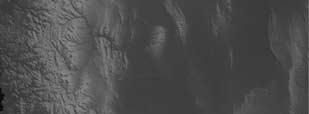
![Figure 1. Map of our study area showing CHARGE seismic stations and regional seismic stations. Solid lines indicate depth contours of the subducting Nazca plate from Cahill and Isacks [1992].](/docs-images/82/86608262/images/2-0.jpg "Nazca plate between 30 and 36 S (Figure 1). The northern half of this study area overlies the central Chilean flat slab segment associated with the Sierras Pampeanas.")
2 Figure 1. Map of our study area showing CHARGE seismic stations and regional seismic stations. Solid lines indicate depth contours of the subducting Nazca plate from Cahill and Isacks [1992]. Nazca plate between 30 and 36 S (Figure 1). The northern half of this study area overlies the central Chilean flat slab segment associated with the Sierras Pampeanas. The southern half overlies a section of Nazca plate that subducts at a normal angle. Our results to the north indicate that while P wave velocities are reduced above the flat slab, S wave velocities are increased, resulting in a dramatic decrease in the V p /V s ratio. The absence of low S wave velocities indicates a lack of fluids or melt above the flat slab, which explains the cessation of volcanism in this region. To the south, we find decreases in V p and V s and increased V p /V s ratios below the modern active arc consistent with the presence of melt. 2. Tectonic Setting [4] The Andean Cordillera of Chile and Argentina can be divided into three segments. North of 28 S and south of 33 S, the modern active volcanic arc overlies regions where the subducting Nazca plate dips at a relatively constant angle of 30. Between these areas lies the central Chilean flat slab segment, which is spatially correlated with the basement cored uplifts of the Sierras Pampeanas and the cessation of modern arc volcanism. The northern and southern transition zones between normal and flat slab subduction are very different from one another. The transition at 28 S is very gradual, starting with the formation of a small bench [Cahill and Isacks, 1992] at 20 S, which gradually widens until the flat slab reaches its broadest extent at 32 S. The northern edge of the flat slab region is better defined by the cessation of arc volcanism at 28 S and the increased seismic activity in the slab between 29 S and 32 S. In contrast, the transition at 33 S is fairly abrupt, going from a very broad flat slab region to a normally dipping slab in less than 2 latitude. The nature of the southern transition zone is ill defined due to a paucity of seismicity below 125 km depth, so it is possible that this change in dip is accommodated either by a tear in the slab or by a sharp bend in the downgoing plate. [5] The history of this region of flat slab subduction has been inferred both by looking at the timing of possible causes for this flattening, and by looking at the age of observable geologic features for which this flattening is presumed responsible. While the causes of flat slab subduction are not indisputably confirmed, one likely contributing factor is the subduction of aseismic oceanic ridges. The spatial correlation between subducting or subducted bathymetric features and regions of flat slab subduction along the Andean margin has been noted repeatedly [Cross and Pilger, 1982; McGeary et al., 1985; von Huene et al., 1997; Gutscher et al., 2000; Ramos et al., 2002]. In the case of the central Chilean flat slab segment, it is the Juan Fernandez Ridge (JFR) which is subducting beneath the South American continent at a rate of about 8.4 cm/yr [Gutscher et al., 2000]. At the time of the breakup of the Farallon plate and the formation of the Nazca plate some 25 Myr ago, the JFR was being subducted obliquely at 20 S. After the breakup, convergence between the plates became almost normal, and between 20 and 12 Ma, the JFR moved rapidly southward, reaching current latitudes 2of20
3 Table 1. Station Information Station Longitude Latitude Elevation, m Seismometer AMER CMG-3ESP AREN CMG-40T BARD STS2 CONS CMG-3ESP ELBO STS2 FCH CMG-3ESP HEDI CMG-3ESP HUER STS2 HURT STS2 JUAN STS2 LENA STS2 LITI CMG-3ESP LLAN CMG-3ESP LOIC STS2 MAUL CMG-3ESP NEGR CMG-3ESP NIEB STS2 PACH STS2 PENA STS2 PICH STS2 RAFA CMG-40T RINC CMG-3ESP SJAV CMG-3ESP USPA STS2 10 Ma [Yanez et al., 2002]. This correlates well with the eastward progression of deformation and arc volcanism, beginning between 20 and 18 Ma and increasing rapidly after 11 Ma [Kay and Abruzzi, 1996; Ramos et al., 2002]. Eventually, volcanism would move over 500 km east before ending completely between 5 and 1.9 Ma [Ramos et al., 2002; Kay and Mpodozis, 2002]. The timing of the uplift in the Sierras Pampeanas is not well constrained, but it is believed to have begun between 10 and 3 Ma [Jordan and Allmendinger, 1986], roughly coeval with the sweep of volcanism through this area. This evidence suggests flattening began to the north between 20 and 18 Ma, with the most dramatic changes at current latitudes occurring between 10 and 5 Ma, reaching its present configuration no later than 2 Ma. [6] The southern half of our study area is characterized today by comparatively normal subduction at a constant dip angle of 30. Modern volcanism is concentrated along the main Cordillera, roughly following the Chile/Argentina border, and is consistent in location and geochemistry with normal subduction-related arc volcanism. 3. Field Deployment and Data [7] The Chile Argentina Geophysical Experiment (CHARGE) consisted of 22 broadband portable seismometers deployed in roughly two transects for 18 months starting in late The seismometers were primarily a mix of STS-2s and Guralp CMG-3ESPs (Table 1). Data were collected using RefTek 72A-08 digitizers recording at 40 samples per second and stored on 80 GB hard drives which were exchanged every 3 4 months. Timing at each station was synchronized using GPS receivers. Instrumentation for this deployment was provided by the Program for Array Seismic Studies of the Continental Lithosphere (PASSCAL) of the Incorporated Research Institutions for Seismology (IRIS). [8] The two transects of this deployment both trended roughly east-west (Figure 1). The northern line was located at 30 S above the flat slab region. The southern line was located at 36 S, above the normally dipping slab. Four stations were deployed between these two transects, complementing previously existing regional networks run by the University of Chile in Santiago, the Instituto Nacional de Prevencion Sismica, and the University of San Juan, Argentina, which report data to the International Seismological Centre (ISC). [9] For this tomography study, we used a total of 142 well located events consisting of 84 events below 70 km depth, presumed to be in the subducting Nazca plate, and 58 crustal events (Figure 2). We picked P and S wave first arrivals and relocated each event using Hypocenter [Lienert and Havskov, 1995]. Only events with azimuthal gaps of less than 180 were used. P waves were picked exclusively on the vertical component, and S waves were picked on the transverse component, initially using the global catalog location to rotate the data. After relocating all the events, events were re-rotated using new hypocenter locations, and all S wave picks were reviewed on the transverse component. We discuss any possible S wave anisotropic effects in section 6.1. The impulsive P and S wave arrivals generated by the deep events were significantly easier to pick than the emergent arrivals generated by the shallow events. However, the large impulsive P wave arrivals from the deep events (and some close in recordings of shallow events) produced acausal precursory arrivals due to the antialiasing FIR filter applied by the RefTek 72A-08 digitizer. We removed the FIR filter effect using the method of Scherbaum and Bouin [1997] before picking the P wave arrival times. The acausal FIR arrival was typically less than 0.25 s before the true first arrival, which is significantly less than the final average travel time residuals of the inversions, which are between 0.45 and 0.5 s. 3of20
![Figure 2. Map of geologic features in our study area. Slab contours are from Cahill and Isacks [1992]. Triangles indicate active volcanos.](/docs-images/82/86608262/images/4-0.jpg "Open circles indicate slab events, and solid circles indicate crustal events. Shaded grey lines indicate the locations of the Juan Fernandez Ridge at the indicated times [Yanez et al., 2001].")
![[10] P and S wave arrivals for the shallow events were more difficult to pick.](/docs-images/82/86608262/images/4-1.jpg "Most recordings were made at distances beyond the crossover distance where the Mohorefracted Pn or Sn phases become the first arrivals. These phases are very emergent and difficult to pick accurately.")


4 Figure 2. Map of geologic features in our study area. Slab contours are from Cahill and Isacks [1992]. Triangles indicate active volcanos. Open circles indicate slab events, and solid circles indicate crustal events. Shaded grey lines indicate the locations of the Juan Fernandez Ridge at the indicated times [Yanez et al., 2001]. [10] P and S wave arrivals for the shallow events were more difficult to pick. Most recordings were made at distances beyond the crossover distance where the Mohorefracted Pn or Sn phases become the first arrivals. These phases are very emergent and difficult to pick accurately. Complicating matters, Sn arrivals for travel paths crossing the southern back-arc region were severely attenuated and impossible to pick. In order to avoid a systematic bias caused by picking all Sn arrivals too late and to maintain a consistent data set, we do not use any S wave picks from shallow events with epicentral distances of greater than 150 km. In total, we used over 1600 P wave picks and over 900 S wave picks from CHARGE stations. After inverting for V p, V s, and V p /V s using only CHARGE station picks, we added data from the regional networks as reported to the ISC catalog. We did not include S wave picks from shallow events beyond 150 km epicentral distance in order to avoid potential bias. Adding the ISC data did not change any of the major features of the tomography, but did improve resolution. With the ISC data included, the data set consists of over 2600 P wave picks and over 1600 S wave picks. 4. Methods [11] There is continuing debate on the best methodology for determining V p, V s, and the V p /V s ratio through seismic tomography. Each of these three quantities gives us important information on the composition and physical state of the volume being studied, yet they are each obviously not entirely independent from one another. We can determine V p and V s relatively independently (assuming fixed event parameters), as they are each tied to the absolute travel times of a particular phase. Errors in P wave picks map directly to errors in the P wave velocity structure but not necessarily to errors in the S wave velocity structure, and vice versa. The V p /V s ratio, on the other hand, is derived from the difference in travel times between the P and S wave arrivals, and as such the accuracy of a given V p /V s measurement is sensitive to errors in both P and S picks and velocity structures. Further complicating the determination of V p /V s is the generally uneven distribution and quality of P and S wave picks. Even if all picks were made with total accuracy, an underresolved S wave anomaly that is related to a well resolved P wave anomaly would produce a spurious V p /V s ratio. A number of authors [e.g., Thurber, 1993; Eberhart-Phillips and Reyners, 1997; Graeber and Asch, 1999] have addressed this issue by inverting directly for V p and V p /V s. This should guarantee that deviations in V p /V s are mandated by the data and are not merely artifacts of uneven resolution. Unfortunately, V s deviations determined from this method by dividing V p by V p /V s suffer from many of the same problems associated with determining V p /V s by inverting for V p and V s. In particular, large P wave anomalies in areas with better P wave coverage than S wave coverage tend to bleed over into the S wave anomalies via an underresolved V p /V s anomaly. Thus, to ensure that observed anomalies either in V p, V s,orv p /V s are not due to a bleed-over effect, it is necessary to invert directly for each quantity. 4of20
5 [12] To that end, in addition to inverting simultaneously for V p and V s, we modified the code of Zhao et al. [1992] to invert simultaneously for V p and the V p /V s ratio. Zhao et al. s method allows for the input of a priori information on crustal structure and the location of the subducting slab which improves ray tracing by allowing for sharp velocity gradients at discontinuities. The ray tracer iteratively uses Snell s law across the model discontinuities, and the pseudobending technique described by Um and Thurber [1987] to determine ray paths through the rest of the volume. A priori information about discontinuities also allows for a more accurate starting model, as initial velocities for crust and mantle follow the contours of the model Moho discontinuity. Velocity deviations are assigned to grid nodes, and are linearly interpolated between these grid nodes when velocities are calculated. We used a grid spacing of km in latitude, longitude, and depth, respectively. Because seismic travel time equations are nonlinear, the equations are linearized and the tomography is performed iteratively using the sparse matrix LSQR inversion method of Paige and Saunders [1982]. [13] Before the inversion in each iteration, events are relocated using the updated 3-D P and S wave velocity models, and travel time residuals recalculated based on the revised locations and velocity models. For the P and S inversion, we tested the effects of including event parameters in the inversion as opposed to relocating events through the 3-D model after each iteration, and found essentially no difference in the velocity models or the event locations between the two methods. [14] For the simultaneous inversion of V p and V p /V s,we added the derivatives for the difference in S wave travel times from P wave travel times (S-P time) to Zhao et al. s [1992] original code (see auxiliary material 1 ). Data for the V p /V s inversion came from stations/event pairs with good P and S picks. To obtain predicted S-P times, we calculated P and S wave ray paths independently. Because the derivatives assume identical ray paths (see auxiliary material), we also tried calculating predicted times along identical ray paths, but the change in predicted S-P times was much smaller than our uncertainty and thus had no significant effect on the tomography results. [15] Our starting mantle model is that of IASPEI-91 [Kennett, 1991], and our input for the slab discontinuity is from Cahill and Isacks [1992]. The tomography allows for an initial velocity deviation in the slab to more closely approximate the likely higher velocities in the cold subducting plate. We tried inverting with and without this slab deviation of 5% and found that it had no significant effect on our upper mantle results. Since our results are insensitive to initial slab deviations and we are uncertain of the exact slab structure, we decided not to include an initial slab deviation in our starting model. Our crustal thicknesses and velocities were taken from Pn [Fromm et al., 2004] and receiver function studies [Gilbert et al., 2003] from the CHARGE experiment. Because most of our crustal earthquake picks are from Pn arrivals, we have very poor crustal resolution. We therefore fix our crustal P wave 1 Auxiliary material is available at ftp://ftp.agu.org/apend/jb/ 2004JB velocity at 6.0 km/s, as determined by Fromm et al. [2004], and a V p /V s ratio of We tested the effects of changing the initial P and S velocities in the crust on the mantle tomography and found that differences tended to affect only amplitudes, and not the general patterns of velocity perturbations. We discuss the effects of different crustal models in section 6.1. [16] In order to remove outliers due to mispicks, we imposed a residual cutoff of 2 s for P waves, 3 s for S waves in the P and S inversion, and 3 s for S-P times in the P and V p /V s inversion. These values were determined by looking at the distribution of residuals versus travel times for the initial model (Figure 3). Damping is necessary in this inversion due to the instability caused by incomplete and inconsistent data [Menke, 1989]. For details on the damping used in this inversion, see the auxiliary material. 1 There are two main ways to determine damping parameters. The traditional method sets the damping equal to the data variance divided by the model variance. This is difficult in seismic tomography because of problems quantifying error in the data prior to the inversion. The other method proposed by Eberhart-Phillips [1986] involves running the tomography for one iteration over a range of damping parameters and plotting data variance versus model variance. The ideal damping value is at the corner of the resulting L curve, beyond which increases in model variance do not produce significant decreases in data variance, and vice versa. In our case, this method produces an ideal damping value of 20 for both the P and S and the P and V p /V s inversions (Figure 4). Changing this damping value ±10 does little to change the basic patterns in the results, but it does affect the amplitude of the deviations. These amplitudes are also affected by the number of iterations used. In order to find the optimal number of iterations, we use our previously determined damping values over 10 iterations, and again plot data variance versus model variance, this time for each iteration. In our case, 2 iterations are optimal for both the P and S and P and V p /V s inversions (Figure 5). Additional iterations may reduce variance more, but would serve only to increase the size of the observed anomalies. The improvement in the residuals can be seen in Figure 3. These constitute a 40.9% and a 44.3% improvement in data fit for the P and S and P and V p /V s inversions, respectively. 5. Resolution Tests [17] To test the resolution of our study, we calculated synthetic travel times through a checkerboard model where the velocity deviation at each grid node used in the original inversion is ±5%. We used the same source-receiver distribution as the actual data set. These calculated times were then inverted for V p and V s to see how much of the original checkerboard pattern could be recovered (Figure 6). Our checkerboard pattern is best recovered for both P and S above the flat slab region. Amplitudes for V p are somewhat underestimated whereas amplitudes for V s are accurately recovered in this area. The overall checkerboard pattern is clearly observable in both V p and V s. To the south, the checkerboard pattern is well recovered for V p, but V s indicates some vertical smearing. Amplitudes for both V p and V s are well recovered in this area. 5of20
6 Figure 3. Residuals versus travel time plots for P, S, and S-P. (top) Residuals before the inversions. (bottom) Residuals after the inversions. P and S-P final residuals are from the P and V p /V s inversion. Final residuals for S are from the P and S inversion. Dashed lines indicate residual cutoffs for P, S, and S-P times. [18] While checkerboard tests are good for observing streaking anomalies, they are not good tests for the recoverability of larger features [Leveque et al., 1993]. To this end, we tested the ability of our inversion to recover a broad flat horizontal anomaly to the north similar in size and amplitude to our observed anomaly above the flat slab and a long narrow thicker anomaly to the south, similar in shape and amplitude to the low velocity zone observed there, following the method of Husen et al. [2003]. This test is also well suited for demonstrating the bleed-over effect discussed in section 4. We generated a synthetic data set by ray tracing through a specified model, and then inverted this synthetic data set without allowing events to be relocated. If we allow events to be relocated, the results are similar, but the bleed-over effect is less pronounced. We performed three different tests, the first with an initial anomaly only in P, the second with an initial anomaly only in S, and the third with an initial anomaly in both P and S resulting in no V p /V s anomaly. We performed this test using both the P and V p /V s inversion and the P and S inversion. The results of these tests indicate that the best way to determine S wave velocity structure is through a simultaneous inversion of V p and V s, and the best way to determine the V p /V s ratio is to invert directly for V p and V p /V s (see Appendix A and Figure 7). V p was insensitive to the inversion method. [19] In Figure 8, we show cross sections for V p, V s, and V p /V s anomalies which we feel best reflect the true resolvability of these synthetic anomalies. V p and V p /V s cross sections are from the P and V p /V s inversion recovering a P only anomaly (i.e., no S anomaly). V s cross sections are from the P and S inversion recovering an S-only anomaly (i.e., no P anomaly). The V p anomaly is best recovered, with good resolution extending east of 68 W. For V s and V p /V s, resolution of the amplitude of the anomaly begins to degrade east of 69 W, with very little resolution east of 68 W. Vertical smearing is also more pronounced to the east in V s and V p /V s than in V p. 6. Results and Sensitivity Analysis [20] We present results for V p and V p /V s from our P and V p /V s inversion and V s from our P and S inversion. Even though we invert for structure below the slab, resolution is poor, so we only show results between the crust and the top of the subducted plate. Results for V p are virtually identical in the two inversions. Results for V s and V p /V s are very similar, except for specific areas (such as the far eastern flat slab region), where there are bleed-over effects. For an example of this effect in the V s results, see Figure 9. Figure 9 also shows initial and final event locations along the subducting flat slab. Prior work [e.g., Reta, 1992] had noted the apparent reverse dip of the subducting plate as determined by earthquake locations, caused by the apparent deeper depths of events below the main cordillera than those located farther east. This effect is seen when events are relocated independently using a 1-D velocity model. However, when these events are relocated in the tomography using full 3-D V p and V s models, these events flatten out, aligning themselves closely at approximately 100 km depth, as suggested by Cahill and Isacks [1992]. [21] We present V p and V s deviations from the starting model in color, and provide absolute velocity contours to facilitate interpretation (Figures 10 15). For V p /V s, we present absolute values in color, where cooler colors (green, blue, purple) indicate V p /V s values that are lower than the starting model, and where warmer colors (yellow, orange, red) indicate V p /V s values that are higher than the starting 6of20
7 wave velocities, high S wave velocities, and an unusually low V p /V s ratio, as can be seen in the cross sections in Figure 10 and the map view slice at 85 km depth in Figure 14. This feature extends some 300 km E-W, 120 km N-S and appears to be between 20 and 40 km thick. P wave velocities in this region range from 7.4 to 8.0 km/s, with the Figure 4. Model versus data variance plots for different damping parameters. Open circles indicate the optimal damping values for each inversion. (a) Model versus data variance for the inversion of V p and the V p /V s ratio. (b) Model versus data variance for the inversion of V p and V s. model. Green dots indicate the earthquake locations determined using the final 3-D velocity models Flat Slab Region [22] Above the flat slab in the northern half of our study area, we find a continuous layer characterized by low P Figure 5. Model versus data variance plots with fixed damping parameters over multiple iterations. Open circles indicate the ideal number of iterations. (a) Model versus data variance for the inversion of V p and the V p /V s ratio. (b) Model versus data variance for the inversion of V p and V s. 7of20
8 Figure 6. Checkerboard resolution test for V p and V s. Input velocity deviation is ±5%. most common velocities lying between 7.6 and 7.8 km/s. At km depth, this is % lower than IASPEI-91 (8.046 km/s), and is similar or even somewhat lower than values found by Myers et al. [1998] under the Altiplano in Bolivia (7.8 km/s). Unlike typical volcanic arcs, however, the S wave velocities above the flat slab are higher than usual. Absolute S wave velocities range between 4.5 and 4.8 km/s with the most common velocities lying between 4.6 and 4.7 km/s, where IASPEI-91 is km/s. This corresponds to a % increase over the starting model. [23] The obvious result of decreased P wave velocities and increased S wave velocities is a decrease in the V p /V s ratio. We find V p /V s ratios between 1.63 and 1.76, with the most common values lying between 1.68 and IASPEI-91 at this depth is This corresponds to a % decrease in V p /V s from the starting model. While absolute values are often less well resolved in tomographies, general patterns of deviations are generally consistent. In our case, the pattern of low V p, high V s, and low V p /V s has been remarkably consistent over a range of methods, starting models, and parameters. Even a conservative velocity deviation of 1.5% for V p and V s, respectively, results in a V p /V s ratio of A 2% deviation produces a V p /V s ratio of [24] We tested the sensitivity of our results to crustal structure by inverting over a range of crustal thicknesses and velocities, and by testing the effect of fixing the crust versus allowing the crustal velocities to change during the inversion. In the case of a fixed crust, the effect of increasing crustal P wave velocities while keeping V p /V s fixed, or thinning the crust (for example, by using a flat Moho at 40 km depth) was to decrease the amplitude of the V p /V s deviation. In general, P wave velocities remained slow, S wave velocities remained fast, but due to the very low amplitudes in V p,thev p /V s ratio ranged from 1.70 to However, constraints from Pn studies [Fromm et al., 2004] indicate that increases in crustal P wave velocities 8of20
9 Figure 7. Map view of the results of the first recovery test for a V p only anomaly. (right) Recovery of V p, V s, and V p /V s using the P and V p /V s inversion. Note the bleed over of the V p anomaly into V s where V p is better recovered than V p /V s. (left) Same test done with the P and S inversion. Note the lack of bleed over into V s. must be coupled with increases in crustal thickness. Thus if we use a higher P wave velocity, we must also use a thicker Moho, and vice versa. The net effect is that if our crust has a velocity/thickness combination that is plausible with respect to the Pn data, our V p, V s, and V p /V s results remain stable. We also looked at the effect of fixing the crustal P wave velocity while varying the crustal V p /V s ratio. While the general pattern of low V p, high V s and low V p /V s persists above the flat slab, decreasing the crustal V p /V s ratio has the effect of raising the observed V p /V s ratio above the flat slab to between 1.69 and 1.77, with typical ratios ranging between 1.71 and However, receiver function studies [Gilbert et al., 2003] indicate that the V p /V s ratio below the main cordillera above the flat slab may be higher than Raising the crustal V p /V s ratio to 1.79 in this study has the effect of lowering the V p /V s ratio above the flat slab to between 1.60 and Thus we feel our estimate of is conservative. 9of20
10 Figure 8. Cross sections of recovery tests for V p, V s, and V p /V s which most accurately represent the true resolvability of these synthetic anomalies. V p and V p /V s are from the P only test using the P and V p /V s inversion. V s is from the S-only anomaly test using the P and S inversion. [25] If we allow the inversion to vary the crustal structure, we again find the same general pattern of low V p, high V s, and low V p /V s, but much of this pattern is smeared into the crust. The result is an extremely low V p /V s ratio in the crust and an only moderately low V p /V s ratio in the mantle above the flat slab. As discussed earlier, independent receiver function analyses, which have much better resolution on crustal structure than this inversion, indicate a much higher V p /V s ratio in the crust, especially west of 67 W. Thus we believe our low V p /V s ratio in the crust to be due to smearing of this anomaly from the mantle sliver into the overlying structure due to poor vertical resolution above the Moho. [26] We also investigated the possibility that our high S wave velocities are due to anisotropy associated with the alignment of olivine crystals in the mantle overlying the flat slab. For the most part, the good azimuthal distribution of rays above the flat slab makes it unlikely that our result is due to anisotropy. We calculated the average V p /V s ratio as a function of back azimuth using Wadati diagrams with picks from deep events north of 33. Results are shown in Figure 16, along with the number of S wave data points in each partition. If azimuthal anisotropy were the cause of changes in V p /V s, we would expect to see 180 periodicity in the results, meaning wedges opposite each other would have similar V p /V s values. While we do see variations in V p /V s, we do not observe this periodicity. We also tried inverting picks from deep events with fixed event parameters as a function of back azimuth, first using only picks with back azimuths between 0 and 180 where the V p /V s ratio is low and then using only picks with back azimuths between 180 and 330 where the V p /V s ratio is high. We find that the latter mostly samples the westernmost portion of the study below the main cordillera where both V p and V s are low, but to the extent that there is coverage above the flat slab, we observe the same characteristic low V p /V s ratio. In the former, the flat slab is well sampled, and again, we observe the same low V p /V s ratio. This suggests that the differences in V p /V s observed in the Wadati diagrams is due to structure, not anisotropy. We recognize that this method may not be sensitive to anisotropy where the fast axis is aligned vertically and the slow axis is horizontally isotropic. However, the fast axis tends to preferentially align itself in the direction of shear [Zhang and Karato, 1995], and it is unlikely above the flat slab that we have any mechanism for vertical shearing. As such, we do not consider this to be a likely cause of our observed results. Seismic recordings at JUAN, located above the center of the flat slab, of events located directly below the station show less than 0.3 s of shear wave splitting (M. Anderson, personal communication, 2004), which is within noise levels for this study. In general, we cannot find any evidence of anisotropy and therefore do not think it has significant effects on the results of this study. This is consistent with the findings of Russo and Silver [1994], who found most of the anisotropy in this region to be located below the Nazca plate. [27] One notable exception to the pervasive low-v p, high-v s, low-v p /V s regime above the flat slab lies beneath the main Cordillera between 70 W and 70.5 W. Here we find a small shallow low-velocity zone in both P and S wave velocities, corresponding to a moderately high V p /V s ratio. This anomaly can be seen in the 65 km depth map view in Figure 13 and in the cross sections of Figure 10. This small anomaly is reminiscent of the low-velocity, 10 of 20
11 Figure 9. Bleed-over effect in CHARGE results at 31.1 S. (top) Cross section of V s deviations from the P and S inversion. (middle) Cross section of V s deviations from the P and V p /V s inversions. (bottom) Cross section of V p from the P and V p /V s inversion. Notice how the low-v p anomaly between 69 W and 68 W bleeds over into the V s anomaly in the P and V p /V s inversion. This low-v s anomaly is not present in the results from the P and S inversion. Open circles indicate final event locations, and solid circles indicate initial event locations. high-v p /V s ratio results commonly found beneath active volcanic arcs, and indeed this anomaly underlies the early Miocene volcanic arc. In map view at 65 km depth, it appears to form a continuous feature from the south below the active arc to the north above the flat slab. However, for reasons discussed in section 6.3, we believe this feature is not due to the same causes as those responsible for low velocities and high V p /V s ratios below normal arc settings but rather has a distinct genesis that happens to have similar seismic effects Transition Zone [28] In the region between the anomalous low-v p, high-v s, low-v p /V s zone to the north and the modern active arc to the south lies the transition zone where the slab rapidly changes from a flat geometry to a normally dipping one. While we cannot resolve whether the slab is torn or continuous in this region, we can image the area immediately above it. We find an ENE trending feature characterized by high V p, high V s, and relatively high V p /V s ratios that extends from the southern edge of the flat slab to the northern edge of modern arc volcanism. This feature is most clearly seen in the 85-km-depth map of the P wave velocity anomalies (Figure 14), extending from between 33 S and 34 S in the west at 71 W to between 32 S and 33 S in the east at 69 W. It is approximately 80 km wide and 280 km long and between 20 and 40 km thick (Figure 11). [29] The high-v p, high-v s, high-v p /V s velocities in this region are consistent with cooled depleted mantle peridotites (Figure 17). This can occur when asthenospheric corner flow is pinched out by the shallowing of the slab in the transition zone. The high velocities indicate that this material is no longer hydrated or melted to any significant extent because the presence of melt or hydrated mineralogies would decrease both P and S wave velocities. Immediately above this region, below the main cordillera, is an area of 11 of 20
12 Figure 10. Results for V p, V s, and V p /V s at 31.1 S latitude. The Moho is from a Pn study by Fromm et al. [2004]. The slab contours are from Cahill and Isacks [1992], and the green dots indicate event locations. V p and V s colors are in percent velocity deviations. Numbers on the contours indicate absolute velocities in km/s. V p contours are in 0.2 km/s increments. V s contours are in 0.1 km/s increments. V p /V s ratio colors are absolute values. Black dots show the locations of grid nodes. pronounced low V p,lowv s, and high V p /V s, which can be seen in the 65-km map view plots (Figure 13) at 32.5 S and 69.5 W. This area is north of the modern active arc, so the anomaly is unlikely to be entirely due to the presence of melt. The high-v p, high-v s anomaly immediately below this area may indicate it is too cool for melt to exist. Instead, it may be a large volume of serpentinized mantle material that was formed when the last of the water from the normally subducting slab was released and moved up through the lower part of the mantle wedge to pool beneath the thickened arc crust. It is probably not coincidence that this pronounced feature lies directly at the corner of the transition zone, and the complicated slab geometry in this region may aid in trapping the fluid-rich serpentinites in this area Southern Region [30] Results from the southern half of this study above the normally subducting slab are consistent with results from other subduction zones around the world [e.g., Graeber and Asch, 1999; Nakajima et al., 2001; Zhao et al., 1992; Zhang et al., 2004]. The mantle is characterized by a low-v p, low-v s, high-v p /V s zone immediately below the active arc (Figures 12, 13, and 14). The exact dimensions of this region are ill defined, but it appears to extend the full length of the active volcanic arc our study area, averaging 80 km E-W and km in thickness. While resolution to the south is not as good as to the north as evidenced by the checkerboard test, we still find resolvable localized P and S velocities of 7.8 and 4.3 km/s, respectively, indicating velocity reductions of 3% and 4.2%. We also find corresponding V p /V s ratios of 1.81, a 1.1% increase over IASP91. These deviations are very similar in amplitude to those found in Bolivia beneath the Western Cordillera and the Los Frailes volcanic field [Myers et al., 1998]. [31] This pattern of low V p,lowv s, and high V p /V s can generally be interpreted as either a serpentinization of 12 of 20
13 Figure 11. Results for V p, V s, and V p /V s at 32.6 S latitude. V p and V s colors are in percent velocity deviations. Numbers on the contours indicate absolute velocities in km/s. V p contours are in 0.2 km/s increments. V s contours are in 0.1 km/s increments. V p /V s ratio colors are absolute values. Black dots show the locations of grid nodes. mantle peridotites or as an indicator of melt. There is virtually no difference between the seismic signatures of melt and those of hydration, so we must look to other information in order to determine which is the cause of a particular low-velocity, high-v p /V s ratio area. Temperature is the key determining factor in most cases. Serpentine is generally unstable at temperatures above 700 [Bose and Ganguly, 1995; Hacker et al., 2003], and melt is unlikely at cooler temperatures, even if water is present. Temperature above a subducting slab is dependent on many factors including rate of subduction, age of the subducting plate, and the amount of frictional heating between the downgoing plate and the overlying mantle [Peacock, 1996]. Given an age of 50 Ma and a convergence rate of 80 mm/yr, temperatures at the location of this low-v p, low-v s, high-v p /V s anomaly are expected to be well above the stability field for serpentinite [Peacock, 1996; Hyndman and Peacock, 2003]. Therefore we believe these results indicate localized pockets of melt, probably induced by the introduction of water into the mantle by the subducting slab. The percent melt represented by these velocity reductions is dependent on the assumed geometry of the melt inclusions. If we assume ellipsoidal melt geometry as done by Schmeling [1985], the percent melt is likely to be between 1% and 1.5% (see Figure 17). However, recent work with more realistic melt geometries [e.g., Hammond and Humphreys, 2000] indicates that shear velocities are likely more affected by small percent melts than previously predicted, resulting in higher predicted V p /V s ratios. This would imply that our results either represent a smaller percent melt than that indicated by Schmeling [1985] and the amplitude of our P wave anomaly is exaggerated or, more likely, our S wave anomaly is underresolved in amplitude. If we assume the latter case is true and our P wave amplitudes are correct, Hammond and Humphreys [2000] predict between 0.6% and 1.1% melt, depending on geometry. [32] In contrast, the low-velocity, high-v p /V s region located above the flat slab which we mentioned in 13 of 20

14 Figure 12. Results for V p, V s, and V p /V s at 34.0 S latitude. The red triangles indicate the locations of active volcanism. V p and V s colors are in percent velocity deviations. Numbers on the contours indicate absolute velocities in km/s. V p contours are in 0.2 km/s increments. V s contours are in 0.1 km/s increments. V p /V s ratio colors are absolute values. Black dots show the locations of grid nodes. section 6.1 is unlikely to be due to melt. Although this feature looks spatially continuous with the low-velocity, high-v p /V s zone to the south, it exists only at shallow levels (65 km), and is located in an area believed to have unusually cool temperatures within the stability field of serpentine [Gutscher et al., 2000; Kay et al., 1988; Hacker et al., 2003]. The northern anomaly is therefore unlikely to be melt, and is probably due to a 15 20% hydration of mantle peridotites (see Figure 17). Although this area is not forearc, the hydration processes may be similar to those responsible for the hydration of the Cascadia forearc [Bostock et al., 2002; Brocher et al., 2003]. The apparent continuity of the low-velocity, high-v p /V s zone from south to north may simply be a consequence of the fact that fluids released at depths of 100 km are causing both anomalies, but the different ambient temperatures result in melt in one case and hydration in the other. Alternatively, the northern anomaly may be due to leftover hydrated mantle from earlier normal geometry subduction. 7. Discussion [33] While the tomography results to the south beneath the active arc are very similar to tomographic results from other subduction zone studies [e.g., Myers et al., 1998; Graeber and Asch, 1999; Nakajima et al., 2001; Zhao et al., 1992; Zhang et al., 2004], the results to the north are unusual and do not lend themselves to simple interpretation. Normally, the pervasive low V p values found above the flat slab might have been interpreted as the presence of hydrous mineralogies or melt, as both are commonly found in subduction zones and both result in P wave velocity 14 of 20


![and Isacks [1992], green stars](/docs-images/82/86608262/images/15-2.jpg "are CHARGE stations, and red")


15 Figure 13. Map views of results for V p, V s, and V p /V s at 65 km depth. Slab contours are from Cahill and Isacks [1992], green stars are CHARGE stations, and red triangles are active volcanoes. V p and V s colors are in percent velocity deviations. Numbers on the contours indicate absolute velocities in km/s. V p contours are in 0.2 km/s increments. V s contours are in 0.1 km/s increments. V p /V s ratio colors are absolute values. Black dots show the locations of grid nodes. Figure 14. Map views of results for V p, V s, and V p /V s at 85 km depth. Shaded lines show the path of the Juan Fernandez Ridge. V p and V s colors are in percent velocity deviations. Numbers on the contours indicate absolute velocities in km/s. V p contours are in 0.2 km/s increments. V s contours are in 0.1 km/s increments. V p /V s ratio colors are absolute values. Black dots show the locations of grid nodes. 15 of 20
16 Figure 15. Map views of results for V p, V s, and V p /V s at 105 km depth. V p and V s colors are in percent velocity deviations. Numbers on the contours indicate absolute velocities in km/s. V p contours are in 0.2 km/s increments. V s contours are in 0.1 km/s increments. V p /V s ratio colors are absolute values. Black dots show the locations of grid nodes. reductions [Hacker et al., 2003; Carlson and Miller, 2003; Christensen, 1996; Hyndman and Peacock, 2003]. In fact, many previous tomography studies of subduction zones investigate only P wave velocity structure, and interpret their low-v p findings as melt or hydrated mineralogies without the benefit of supporting V s or V p /V s results [e.g., Husen et al., 2003; Zhao et al., 1995]. However, the equally pervasive high V s values found in our study contradict this interpretation as both melt and hydrated mineralogies would serve to decrease V s, not increase it. This combination of low V p and high V s is reflected in the unusually low V p /V s ratio which characterizes large volumes of material above the flat slab. [34] While low V p /V s values in the crust are not uncommon [e.g., Nakajima et al., 2001; Zhang et al., 2004], low V p /V s values in the mantle are very rare. One exception is Zhang et al. [2004], who find evidence of low-v p /V s zones in the subducted Pacific plate beneath northern Japan at depths of over 150 km. They interpret these as regions of dehydrated serpentine, where the water released from the crystal structure collects as free water in pore spaces. The effect of free water in pore spaces is dependent on the geometry of the pores, but according to Sato and Ito [2002], spheroidal pore spaces produce decreased V p /V s ratios. This interpretation cannot be applied to our findings, as the presence of free water in spheroidal pore spaces has the effect of decreasing V s, not increasing it. [35] In order to determine which mineralogies might exhibit our observed seismic behavior, we investigate the seismic properties of common upper mantle end-member compositions using the method of Hacker et al. [2003]. Figure 17a shows the V s and V p /V s properties for the Mg and Fe end-member compositions of the most common mantle mineralogies: olivine, orthopyroxene, and clinopyroxene. It is clear that in all cases, the Mg end-member is closer to our flat slab result than the Fe end-member. The best fit is to pure enstatite, the Mg end-member of orthopyroxene. [36] We then investigated specific compositions which are likely to be found in a subduction zone environment (Figure 17b). A 95% enstatite, 5% ferrosilicate orthopyroxene composition comes fairly close to our observed high V s,lowv p /V s values. Orthopyroxenites have been found to constitute minor populations in mantle xenoliths [Smith et al., 1999; Ertan and Leeman, 1996] and are generally interpreted as being samples of metasomatized mantle due to the interaction of silica-rich fluids with mantle peridotites. These fluids react with olivine to form orthopyroxenites at temperature conditions between 700 C and 1000 C [McInnes, 1996] which are above the stability field of serpentinite at these pressures [Hacker et al., 2003] but are below the solidus. This provides information about the temperature above the slab at the time this metasomatization occurred but does not constrain any subsequent changes in temperature. [37] It is possible that this metasomatization of olivine to orthopyroxene occurred on a massive scale above the flat slab. Fluids involved in this process can no longer be present in large quantity because this would result in a decrease in the S wave velocities [Sato and Ito, 2002; Hacker et al., 2003]. This implies the transit time of the fluid through the lower portion of the overlying mantle must be short, and that this fluxing by silicious fluids was a 16 of 20
Seismological laboratory in Agua Negra tunnel
 Instituto Geofísico Sismológico Volponi Universidad Nacional de San Juan Seismological laboratory in Agua Negra tunnel Buenos Aires, Abril 2011 Why a Seismological laboratory in Agua Negra tunnel? Earthquake
The importance of the South-American plate motion and the Nazca Ridge subduction on flat subduction below South Peru
 Chapter 7 The importance of the South-American plate motion and the Nazca Ridge subduction on flat subduction below South Peru Abstract Flat subduction near Peru occurs only where the thickened crust of
Tracing rays through the Earth
 Tracing rays through the Earth Ray parameter p: source receiv er i 1 V 1 sin i 1 = sin i 2 = = sin i n = const. = p V 1 V 2 V n p is constant for a given ray i 2 i 3 i 4 V 2 V 3 V 4 i critical If V increases
Tomographic imaging of P wave velocity structure beneath the region around Beijing
 403 Doi: 10.1007/s11589-009-0403-9 Tomographic imaging of P wave velocity structure beneath the region around Beijing Zhifeng Ding Xiaofeng Zhou Yan Wu Guiyin Li and Hong Zhang Institute of Geophysics,
Crustal structure of the south-central Andes Cordillera and backarc region from regional waveform modelling
 Geophys. J. Int. (27) 17, 858 875 doi: 1.1111/j.1365-246X.27.3452.x Crustal structure of the south-central Andes Cordillera and backarc region from regional waveform modelling P. Alvarado, 1,2 S. Beck
2008 Monitoring Research Review: Ground-Based Nuclear Explosion Monitoring Technologies
 STRUCTURE OF THE KOREAN PENINSULA FROM WAVEFORM TRAVEL-TIME ANALYSIS Roland Gritto 1, Jacob E. Siegel 1, and Winston W. Chan 2 Array Information Technology 1 and Harris Corporation 2 Sponsored by Air Force
USU 1360 TECTONICS / PROCESSES
 USU 1360 TECTONICS / PROCESSES Observe the world map and each enlargement Pacific Northwest Tibet South America Japan 03.00.a1 South Atlantic Arabian Peninsula Observe features near the Pacific Northwest
Data Repository Item
 Data Repository Item 2009003 An abrupt transition from magma-starved to magma-rich rifting in the eastern Black Sea Donna J. Shillington, Caroline L. Scott, Timothy A. Minshull, Rosemary A. Edwards, Peter
Lithospheric and upper mantle structure of central Chile and Argentina
 Geophys. J. Int. (2006) 165, 383 398 doi: 10.1111/j.1365-246X.2006.02867.x Lithospheric and upper mantle structure of central Chile and Argentina Hersh Gilbert, Susan Beck and George Zandt University of
Seismic Anisotropy and Mantle Flow in the Izu-Bonin-Mariana Subduction System
 Seismic Anisotropy and Mantle Flow in the Izu-Bonin-Mariana Subduction System Matthew J. Fouch (Department of Geological Sciences, Arizona State University, Tempe, AZ 85287, email: fouch@asu.edu) INTRODUCTION
4-D Geodynamic Modeling With Data Assimilation: Subduction and Continental Evolution
 4-D Geodynamic Modeling With Data Assimilation: Subduction and Continental Evolution PI: Lijun Liu Department of Geology, University of Illinois at Urbana-Champaign Corresponding author: Lijun Liu, ljliu@illinois.edu
overlie the seismogenic zone offshore Costa Rica, making the margin particularly well suited for combined land and ocean geophysical studies (Figure
 Chapter 1 Introduction Historically, highly destructive large magnitude (M w >7.0) underthrusting earthquakes nucleate along the shallow segment of subduction zone megathrust fault, and this region of
Supplementary Figure 1. Distribution of seismic event locations determined using the final 3-D velocity model. We separate the crust-related
 Supplementary Figure 1. Distribution of seismic event locations determined using the final 3-D velocity model. We separate the crust-related seismicity at depths of less than 40 km (panel A) from the deeper
Seismic anisotropy above and below the subducting Nazca lithosphere in southern South America
 JOURNAL OF GEOPHYSICAL RESEARCH, VOL. 117,, doi:10.1029/2012jb009538, 2012 Seismic anisotropy above and below the subducting Nazca lithosphere in southern South America Julia G. MacDougall, 1 Karen M.
09/06/2017. The orogenic cycle in the Andes: Arc magmatism and delamination as control of the fold and thrust belts
 The orogenic cycle in the Andes: Arc magmatism and delamination as control of the fold and thrust belts Victor A. Ramos Laboratorio de Tectónica Andina Instituto de Estudios Andinos Don Pablo Groeber Universidad
Tomography of the 2011 Iwaki earthquake (M 7.0) and Fukushima
 and Fukushima") 1 2 3 Auxiliary materials for Tomography of the 2011 Iwaki earthquake (M 7.0) and Fukushima nuclear power plant area 4 5 6 7 8 9 Ping Tong 1,2, Dapeng Zhao 1 and Dinghui Yang 2 [1] {Department of Geophysics,
1 2 3 Auxiliary materials for Tomography of the 2011 Iwaki earthquake (M 7.0) and Fukushima nuclear power plant area 4 5 6 7 8 9 Ping Tong 1,2, Dapeng Zhao 1 and Dinghui Yang 2 [1] {Department of Geophysics,
GEOPHYSICAL RESEARCH LETTERS, VOL. 35, L14308, doi: /2008gl034461, 2008
 Click Here for Full Article GEOPHYSICAL RESEARCH LETTERS, VOL. 35,, doi:10.1029/2008gl034461, 2008 Tomographic evidence for hydrated oceanic crust of the Pacific slab beneath northeastern Japan: Implications
M. Koch and T.H. Münch. Department of Geohydraulics and Engineering Hydrology University of Kassel Kurt-Wolters-Strasse 3 D Kassel
 Simultaneous inversion for 3D crustal and lithospheric structure and regional hypocenters beneath Germany in the presence of an anisotropic upper mantle M. Koch and T.H. Münch Department of Geohydraulics
A seismic refraction study of the Cocos plate offshore Nicaragua and Costa Rica Harm Van Avendonk (UTIG, UT Austin)
") A seismic refraction study of the Cocos plate offshore Nicaragua and Costa Rica Harm Van Avendonk (UTIG, UT Austin)! October 18, 2012 "#$%&'($)*!+,!-&./(!01!2/(+! Plate tectonics:!!large fluxes of solids
A seismic refraction study of the Cocos plate offshore Nicaragua and Costa Rica Harm Van Avendonk (UTIG, UT Austin)! October 18, 2012 "#$%&'($)*!+,!-&./(!01!2/(+! Plate tectonics:!!large fluxes of solids
Seismic structure in southern Peru: Evidence for a smooth contortion between flat and normal subduction of the Nazca plate
 Chapter 4 Seismic structure in southern Peru: Evidence for a smooth contortion between flat and normal subduction of the Nazca plate 4.1 Abstract Rapid changes in slab geometry are typically associated
Plate Tectonics. entirely rock both and rock
 Plate Tectonics I. Tectonics A. Tectonic Forces are forces generated from within Earth causing rock to become. B. 1. The study of the origin and arrangement of Earth surface including mountain belts, continents,
Activity Pacific Northwest Tectonic Block Model
 Activity Pacific Northwest Tectonic Block Model The Cascadia tectonic margin is caught between several tectonic forces, during the relentless motions of the giant Pacific Plate, the smaller subducting
Some aspects of seismic tomography
 Some aspects of seismic tomography Peter Shearer IGPP/SIO/U.C. San Diego September 7, 2009 Earthquake Research Institute Part 1: Global Tomography P velocity perturbations 200 km 1000 km 2700 km MIT 2006
Structural Cause of Missed Eruption in the Lunayyir Basaltic
 GSA DATA REPOSITORY 2015140 Supplementary information for the paper Structural Cause of Missed Eruption in the Lunayyir Basaltic Field (Saudi Arabia) in 2009 Koulakov, I., El Khrepy, S., Al-Arifi, N.,
Subduction zones are complex plate boundaries in which variable geometry and structure can be
 1 Chapter 1 Introduction Subduction zones are complex plate boundaries in which variable geometry and structure can be seismically observed. The along-strike transition from flat to normal subduction is
Dynamic Subsidence and Uplift of the Colorado Plateau. Supplementary Material
 GSA DATA REPOSITORY 2010177 Liu and Gurnis Dynamic Subsidence and Uplift of the Colorado Plateau Supplementary Material Lijun Liu and Michael Gurnis Seismological Laboratory California Institute of Technology
Directed Reading. Section: The Theory of Plate Tectonics. to the development of plate tectonics, developed? HOW CONTINENTS MOVE
 Skills Worksheet Directed Reading Section: The Theory of Plate Tectonics 1. The theory that explains why and how continents move is called. 2. By what time period was evidence supporting continental drift,
GEOPHYSICAL RESEARCH LETTERS, VOL. 37, L02304, doi: /2009gl041835, 2010
 Click Here for Full Article GEOPHYSICAL RESEARCH LETTERS, VOL. 37,, doi:10.1029/2009gl041835, 2010 Seismic structure of the Longmen Shan region from S wave tomography and its relationship with the Wenchuan
9th Workshop on Three-Dimensional Modelling of Seismic Waves Generation, Propagation and their Inversion
 1965-36 9th Workshop on Three-Dimensional Modelling of Seismic Waves Generation, Propagation and their Inversion 22 September - 4 October, 2008 Tomography and Active Tectonics in Kanto, Japan Francis T.
Late 20 th Century Tests of the Continental Drift Hypothesis
 Late 20 th Century Tests of the Continental Drift Hypothesis 5 Characteristics of the Ocean Trenches Unless otherwise noted the artwork and photographs in this slide show are original and by Burt Carter.
A) B) C) D) 4. Which diagram below best represents the pattern of magnetic orientation in the seafloor on the west (left) side of the ocean ridge?
 B) C) D) 4. Which diagram below best represents the pattern of magnetic orientation in the seafloor on the west (left) side of the ocean ridge?") 1. Crustal formation, which may cause the widening of an ocean, is most likely occurring at the boundary between the A) African Plate and the Eurasian Plate B) Pacific Plate and the Philippine Plate C)
1. Crustal formation, which may cause the widening of an ocean, is most likely occurring at the boundary between the A) African Plate and the Eurasian Plate B) Pacific Plate and the Philippine Plate C)
PLATE TECTONIC PROCESSES
 Lab 9 Name Sec PLATE TECTONIC PROCESSES 1. Fill in the blank spaces on the chart with the correct answers. Refer to figures 2.3, 2.4 p.33 (2.2 and 2.3 on p. 23) as needed. 2. With your knowledge of different
Seismic ray path variations in a 3D global velocity model
 Physics of the Earth and Planetary Interiors 141 (2004) 153 166 Seismic ray path variations in a 3D global velocity model Dapeng Zhao, Jianshe Lei Geodynamics Research Center, Ehime University, Matsuyama
Structure of the Earth and the Origin of Magmas
 Page 1 of 12 EENS 2120 Petrology Tulane University Prof. Stephen A. Nelson Structure of the Earth and the Origin of Magmas This document last updated on 23-Jan-2015 Magmas do not form everywhere beneath
Travel time tomography of western North America with a new arrival time data set
 Chapter 7 Travel time tomography of western North America with a new arrival time data set 7.1 Introduction The west coast of North America has been, and still continues to be, a site of complex deformation
Whole Earth Structure and Plate Tectonics
 Whole Earth Structure and Plate Tectonics Processes in Structural Geology & Tectonics Ben van der Pluijm WW Norton+Authors, unless noted otherwise 4/5/2017 14:45 We Discuss Whole Earth Structure and Plate
Earthquake patterns in the Flinders Ranges - Temporary network , preliminary results
 Earthquake patterns in the Flinders Ranges - Temporary network 2003-2006, preliminary results Objectives David Love 1, Phil Cummins 2, Natalie Balfour 3 1 Primary Industries and Resources South Australia
Crustal thickness estimation beneath the southern central Andes at 30 S and 36 SfromS wave receiver function analysis
 Geophys. J. Int. (2008) 174, 249 254 doi: 10.1111/j.1365-246X.2008.03780.x Crustal thickness estimation beneath the southern central Andes at 30 S and 36 SfromS wave receiver function analysis Benjamin
5: ABSOLUTE PLATE MOTIONS & HOTSPOTS
 5-1 5: ABSOLUTE PLATE MOTIONS & HOTSPOTS 1 Relative motions between plates are most important In some applications important to consider absolute plate motions, those with respect to the deep mantle ABSOLUTE
The Earth s Structure from Travel Times
 from Travel Times Spherically symmetric structure: PREM - Crustal Structure - Upper Mantle structure Phase transitions Anisotropy - Lower Mantle Structure D D - Structure of of the Outer and Inner Core
Earth Movement and Resultant Landforms
 Earth Movement and Resultant Landforms Structure of the Earth Lithosphere : earth s crust Asthenosphere : upper mantle zone where material is near its melting point & acts almost like liquid (appprox.
Chapter 12 Lecture. Earth: An Introduction to Physical Geology. Eleventh Edition. Earth s Interior. Tarbuck and Lutgens Pearson Education, Inc.
 Chapter 12 Lecture Earth: An Introduction to Physical Geology Eleventh Edition Earth s Interior Tarbuck and Lutgens Earth s Internal Structure Earth s interior can be divided into three major layers defined
4 Deforming the Earth s Crust
 CHAPTER 7 4 Deforming the Earth s Crust SECTION Plate Tectonics BEFORE YOU READ After you read this section, you should be able to answer these questions: What happens when rock is placed under stress?
Plate Tectonics: The New Paradigm
 Earth s major plates Plate Tectonics: The New Paradigm Associated with Earth's strong, rigid outer layer: Known as the lithosphere Consists of uppermost mantle and overlying crust Overlies a weaker region
3. PLATE TECTONICS LAST NAME (ALL IN CAPS): FIRST NAME: PLATES
: FIRST NAME: PLATES") LAST NAME (ALL IN CAPS): FIRST NAME: PLATES 3. PLATE TECTONICS The outer layers of the Earth are divided into the lithosphere and asthenosphere. The division is based on differences in mechanical properties
LAST NAME (ALL IN CAPS): FIRST NAME: PLATES 3. PLATE TECTONICS The outer layers of the Earth are divided into the lithosphere and asthenosphere. The division is based on differences in mechanical properties
Imaging the Gutenberg Seismic Discontinuity beneath the Oceanic Crust of the North American Plate
 Imaging the Gutenberg Seismic Discontinuity beneath the Oceanic Crust of the North American Plate Robbie Burgess 11-25-15 Dr. Nicholas Schmerr GEOL 394 1 1. Abstract: The lithosphere-asthenosphere boundary
Subduction zones 3 arc magmatism
 5. 3 Subduction zones 3 arc magmatism Where can we observe magmatic/volcanic activities along subduction zones? Characteristics of arc magmatism (vs. mid-ocean ridge/intraplate magmatism) Structure of
ANOTHER MEXICAN EARTHQUAKE! Magnitude 7.1, Tuesday Sept. 19, 2017
 ANOTHER MEXICAN EARTHQUAKE! Magnitude 7.1, Tuesday Sept. 19, 2017 Why is there no oceanic crust older than 200 million years? SUBDUCTION If new oceanic crust is being continuously created along the earth
Sendai Earthquake NE Japan March 11, Some explanatory slides Bob Stern, Dave Scholl, others updated March
 Sendai Earthquake NE Japan March 11, 2011 Some explanatory slides Bob Stern, Dave Scholl, others updated March 14 2011 Earth has 11 large plates and many more smaller ones. Plates are 100-200 km thick
Estimation of S-wave scattering coefficient in the mantle from envelope characteristics before and after the ScS arrival
 GEOPHYSICAL RESEARCH LETTERS, VOL. 30, NO. 24, 2248, doi:10.1029/2003gl018413, 2003 Estimation of S-wave scattering coefficient in the mantle from envelope characteristics before and after the ScS arrival
Magnitude 7.0 PERU. This region of the Andes is a sparsely populated area, there were no immediate reports of injuries or damage.
 A magnitude 7.0 earthquake occurred in southeastern Peru on Friday about 27 kilometers northeast of the town of Azángaro, Peru, near the border with Bolivia. The earthquake occurred at a depth of 257.4
Controlled-source electromagnetic imaging of the Middle America Trench o"shore Nicaragua
 Controlled-source electromagnetic imaging of the Middle America Trench o"shore Nicaragua Kerry Key Scripps Institution of Oceanography Collaborators: Samer Naif (SIO, now LDEO), Steven Constable (SIO),
Unit Topics. Topic 1: Earth s Interior Topic 2: Continental Drift Topic 3: Crustal Activity Topic 4: Crustal Boundaries Topic 5: Earthquakes
 The Dynamic Earth Unit Topics Topic 1: Earth s Interior Topic 2: Continental Drift Topic 3: Crustal Activity Topic 4: Crustal Boundaries Topic 5: Earthquakes Topic 1: Earth s Interior Essential Question:
Beneath our Feet: The 4 Layers of the Earty by Kelly Hashway
 Beneath our Feet: The 4 Layers of the Earty by Kelly Hashway The Earth is more than a giant ball made up of dirt, rocks, and minerals. The Earth may look like a giant ball from when looking at it from
Figures S1 S4 show the measurements taken from the synthetic vespagrams where a)
") Figures S1 S4 show the measurements taken from the synthetic vespagrams where a) is the differential travel time versus the Dʺ discontinuity height, b) is the differential travel time versus δv S, c) is
Figures S1 S4 show the measurements taken from the synthetic vespagrams where a) is the differential travel time versus the Dʺ discontinuity height, b) is the differential travel time versus δv S, c) is
Imaging Moho topography beneath the Alps by multdisciplinary seismic tomography
 Imaging Moho topography beneath the Alps by multdisciplinary seismic tomography Edi Kissling ETH Zürich SPP short course February 1+2, 218, Berlin, Germany Alpine Moho map from CSS Moho uncertainty derived
Captain s Tryouts 2017
 Captain s Tryouts 2017 Dynamic Planet Test Written by: Araneesh Pratap (Chattahoochee High School) Name: Date: Answer all questions on the answer sheet. Point values are given next to each question or
Supplementary Material
 1 Supplementary Material 2 3 4 Interseismic, megathrust earthquakes and seismic swarms along the Chilean subduction zone (38-18 S) 5 6 7 8 9 11 12 13 14 1 GPS data set We combined in a single data set
Plate Tectonics. Structure of the Earth
 Plate Tectonics Structure of the Earth The Earth can be considered as being made up of a series of concentric spheres, each made up of materials that differ in terms of composition and mechanical properties.
Mantle flow and multistage melting beneath the Galápagos hotspot revealed by seismic imaging
 Mantle flow and multistage melting beneath the Galápagos hotspot revealed by seismic imaging Darwin R. Villagómez, Douglas R. Toomey, Dennis J. Geist, Emilie E. E. Hooft, & Sean C. Solomon Joint Inversion
Continental Margin Geology of Korea : Review and constraints on the opening of the East Sea (Japan Sea)
") Continental Margin Geology of Korea : Review and constraints on the opening of the East Sea (Japan Sea) Han-Joon Kim Marine Satellite & Observation Tech. Korea Ocean Research and Development Institute
Continental Margin Geology of Korea : Review and constraints on the opening of the East Sea (Japan Sea) Han-Joon Kim Marine Satellite & Observation Tech. Korea Ocean Research and Development Institute
Along the center of the mid-ocean ridge is a rift valley that forms when the plates separate.
 Newly formed rock from rising magma rises above sea floor and forms mountain ranges known as midocean ridges. Along the center of the mid-ocean ridge is a rift valley that forms when the plates separate.
Global surface-wave tomography
 Global surface-wave tomography Lapo Boschi (lapo@erdw.ethz.ch) October 7, 2009 Love and Rayleigh waves, radial anisotropy Whenever an elastic medium is bounded by a free surface, coherent waves arise that
27th Seismic Research Review: Ground-Based Nuclear Explosion Monitoring Technologies
 P AND S WAVE VELOCITY STRUCTURE OF THE CRUST AND UPPER MANTLE UNDER CHINA AND SURROUNDING AREAS FROM BODY AND SURFACE WAVE TOMOGRAPHY M. Nafi Toksöz, Robert D. Van der Hilst, Youshun Sun, and Chang Li
Ambient Noise Tomography in the Western US using Data from the EarthScope/USArray Transportable Array
 Ambient Noise Tomography in the Western US using Data from the EarthScope/USArray Transportable Array Michael H. Ritzwoller Center for Imaging the Earth s Interior Department of Physics University of Colorado
GEO-DEEP9300 Lithosphere and Asthenosphere: Composition and Evolution
 GEO-DEEP9300 Lithosphere and Asthenosphere: Composition and Evolution Summary Presentation The Structural Evolution of the Deep Continental Lithosphere Focused on the Junction of Arabian, Eurasian and
2. Explain why there are these two predominate elevations. (Hint: think about isostasy and the type of materials we used to demonstrate buoyancy).
.") IDS 102 Plate Tectonics Questions Part I: Observations- Four maps of world are positioned around the room. Answer the questions associated with each map and record your general observations about the maps.
IDS 102 Plate Tectonics Questions Part I: Observations- Four maps of world are positioned around the room. Answer the questions associated with each map and record your general observations about the maps.
The influence of short wavelength variations in viscosity on subduction dynamics
 1 Introduction Deformation within the earth, driven by mantle convection due primarily to cooling and subduction of oceanic lithosphere, is expressed at every length scale in various geophysical observations.
3D IMAGING OF THE EARTH S MANTLE: FROM SLABS TO PLUMES
 3D IMAGING OF THE EARTH S MANTLE: FROM SLABS TO PLUMES Barbara Romanowicz Department of Earth and Planetary Science, U. C. Berkeley Dr. Barbara Romanowicz, UC Berkeley (KITP Colloquium 9/11/02) 1 Cartoon
SUPPLEMENTARY INFORMATION
 SUPPLEMENTARY INFORMATION Miocene drainage reversal of the Amazon River driven by plate-mantle interaction. Shephard, G.E., Müller, R.D., Liu, L., Gurnis, M. Supplementary Figures SOM Figure 1. Non-dimensional
Continental Drift and Plate Tectonics
 Continental Drift and Plate Tectonics Continental Drift Wegener s continental drift hypothesis stated that the continents had once been joined to form a single supercontinent. Wegener proposed that the
crustal thicknesses. earthquakes as in recorded
 LEVEU 42 P& 4 9 Source: Cornell University, Ithaca NY, Department of Geological Sciences. Contract N00014-75-C-1121 Date: 1979 Title: Pn, Sn Seismic Propagation in the Upper Mantle SUMMARY OF RESULTS OF
Dynamic Crust Practice
 1. Base your answer to the following question on the cross section below and on your knowledge of Earth science. The cross section represents the distance and age of ocean-floor bedrock found on both sides
Full file at
 Chapter 2 PLATE TECTONICS AND PHYSICAL HAZARDS MULTIPLE-CHOICE QUESTIONS 1. What direction is the Pacific Plate currently moving, based on the chain of Hawaiian Islands with only the easternmost island
C3.4.1 Vertical (radial) variations in mantle structure
 variations in mantle structure") C3.4 Mantle structure Mantle behaves as a solid on short time scales (seismic waves travel through it and this requires elastic behaviour). Over geological time scales the mantle behaves as a very viscous
C3.4 Mantle structure Mantle behaves as a solid on short time scales (seismic waves travel through it and this requires elastic behaviour). Over geological time scales the mantle behaves as a very viscous
SOEE3250/5675/5115 Inverse Theory Lecture 10; notes by G. Houseman
 SOEE3250/5675/5115 Inverse Theory Lecture 10; notes by G. Houseman Travel-time tomography Examples of regional lithospheric tomography CBP / SCP projects data acquisition: array / sources arrival time
Changbaishan volcanism in northeast China linked to subduction-induced mantle upwelling
 SUPPLEMENTARY INFORMATION DOI: 10.1038/NGEO2166 Changbaishan volcanism in northeast China linked to subduction-induced mantle upwelling Youcai Tang, Masayuki Obayashi, Fenglin Niu, Stephen P. Grand, Yongshun
Data Repository Item For: Kinematics and geometry of active detachment faulting beneath the TAG hydrothermal field on the Mid-Atlantic Ridge
 GSA Data Repository Item: 2007183 Data Repository Item For: Kinematics and geometry of active detachment faulting beneath the TAG hydrothermal field on the Mid-Atlantic Ridge Brian J. demartin 1*, Robert
Plate Tectonics Lab II: Background Information
 Plate Tectonics Lab II: Background Information This lab is based on a UW ESS101 Lab. Note: Hand in only the Answer Sheet at the back of this guide to your Instructor Introduction One of the more fundamental
28th Seismic Research Review: Ground-Based Nuclear Explosion Monitoring Technologies
 GROUND TRUTH HYPOCENTERS AND 3D CRUSTAL VELOCITY STRUCTURE IN CENTRAL ASIA FROM IN-COUNTRY NETWORKS Thomas de la Torre 1, Gaspar Monsalve-Mejia 1, Anne F. Sheehan 1, Charlotte Rowe 2, and Michael Begnaud
29th Monitoring Research Review: Ground-Based Nuclear Explosion Monitoring Technologies
 SASIA3D: A 3-D CRUST AND UPPER-MANTLE VELOCITY MODEL OF SOUTH ASIA DERIVED FROM JOINT INVERSION OF P-WAVE TRAVEL TIMES AND SURFACE-WAVE DISPERSION DATA William L. Rodi 1 and Delaine T. Reiter 2 Massachusetts
Earthquakes. Earthquakes are caused by a sudden release of energy
 Earthquakes Earthquakes are caused by a sudden release of energy The amount of energy released determines the magnitude of the earthquake Seismic waves carry the energy away from its origin Fig. 18.1 Origin
The ~ Ma magmatism along the Mesozoic arc is far more voluminous than would be expected for a typical arc.
 The ~120-80 Ma magmatism along the Mesozoic arc is far more voluminous than would be expected for a typical arc. Is Hildebrand s model substantially different from the under-thrusting of continental sediments
Caribbean OBS Fault Research Survey. Iniciative (COFRESI)
") Caribbean OBS Fault Research Survey Iniciative (COFRESI) May 6, 2013 PROPOSAL Submitted to: National Science Fundation Submitted by: Department of Geology, University of Puerto Rico at Mayagüez Proposal
Caribbean OBS Fault Research Survey Iniciative (COFRESI) May 6, 2013 PROPOSAL Submitted to: National Science Fundation Submitted by: Department of Geology, University of Puerto Rico at Mayagüez Proposal
Earth. Temp. increases with depth, the thermal gradient is 25 o C/km. Pressure and density also increase with depth.
 Plate Tectonics Earth Earth overall average density = 5.5 g/cm 3. Temp. increases with depth, the thermal gradient is 25 o C/km. Pressure and density also increase with depth. Spheroid: with a longer major
Regional and local variations in geochemistry and tectonics along and across Central America
 Regional and local variations in geochemistry and tectonics along and across Central America Michael J. Carr, Department of Geological Sciences, Wright Lab Rutgers University, 610 Taylor Rd., Piscataway
Plate Tectonics 3. Where Does All the Extra Crust Go?
 Plate Tectonics 3 Where Does All the Extra Crust Go? Unless otherwise noted the artwork and photographs in this slide show are original and by Burt Carter. Permission is granted to use them for non-commercial,
Lecture 2: Deformation in the crust and the mantle. Read KK&V chapter 2.10
 Lecture 2: Deformation in the crust and the mantle Read KK&V chapter 2.10 Tectonic plates What are the structure and composi1on of tectonic plates? Crust, mantle, and lithosphere Crust relatively light
Effects of Change in Slab Geometry on the Mantle Flow and Slab Fabric in Southern. Peru
 Effects of Change in Slab Geometry on the Mantle Flow and Slab Fabric in Southern Peru Sanja Knezevic Antonijevic a*, Lara S. Wagner b, Susan L. Beck c, Maureen D. Long d, George Zandt c, Hernando Tavera
High-precision location of North Korea s 2009 nuclear test
 Copyright, Seismological Research Letters, Seismological Society of America 1 High-precision location of North Korea s 2009 nuclear test Lianxing Wen & Hui Long Department of Geosciences State University
Structure of the Earth
 Structure of the Earth Compositional (Chemical) Layers Crust: Low density Moho: Density boundary between crust and mantle Mantle: Higher density High in Magnesium (Mg) and Iron (Fe) Core: High in Nickel
12. The diagram below shows the collision of an oceanic plate and a continental plate.
 Review 1. Base your answer to the following question on the cross section below, which shows the boundary between two lithospheric plates. Point X is a location in the continental lithosphere. The depth
Chapter Two. Figure 02_02. Geography of the Ocean Basins. The Sea Floor
 Chapter Two The Sea Floor Geography of the Ocean Basins Figure 02_02 The world ocean is the predominant feature on the Earth in total area. In the Northern Hemisphere, 61% of the total area is ocean. In
Plate Tectonics. In 1912 Alfred Wegener ( ) proposed that: the continents were once compressed into a single protocontinent which he called
 proposed that: the continents were once compressed into a single protocontinent which he called") Plate Tectonics In 1912 Alfred Wegener (1880-1930) proposed that: the continents were once compressed into a single protocontinent which he called Pangaea (meaning "all lands"), and over time they have
Plate Tectonics In 1912 Alfred Wegener (1880-1930) proposed that: the continents were once compressed into a single protocontinent which he called Pangaea (meaning "all lands"), and over time they have
DR
 DR2003071 0 0 270 0 30 0 90 0 60 0 120 0 150 0 90 0 180 0 180 0 A) RadialReceiverFunctions B ackazimuth (in degrees relative to north) -135-90 -45 0 45 90 135 180-5.0-2.5 Tangential R eceiver Functions
Plate Tectonics: A Scientific Revolution Unfolds
 Chapter 2 Lecture Earth: An Introduction to Physical Geology Eleventh Edition Plate Tectonics: A Scientific Revolution Unfolds Tarbuck and Lutgens From Continental Drift to Plate Tectonics Prior to the
Seismic characterization of mantle flow in subduction systems: Can we resolve a hydrated mantle wedge?
 Earth and Planetary Science Letters 243 (2006) 632 649 www.elsevier.com/locate/epsl Seismic characterization of mantle flow in subduction systems: Can we resolve a hydrated mantle wedge? Teresa Mae Lassak
Basic Ray Tracing. Rick Aster and Sue Bilek. October 3, 2003
 Basic Ray Tracing Rick Aster and Sue Bilek October 3, 3 A key observation that we can make about a seismic signal is its arrival time. From systematic observations of arrival times, we can deduce useful
Moho (Mohorovicic discontinuity) - boundary between crust and mantle
 - boundary between crust and mantle") Earth Layers Dynamic Crust Unit Notes Continental crust is thicker than oceanic crust Continental Crust Thicker Less Dense Made of Granite Oceanic Crust Thinner More Dense Made of Basalt Moho (Mohorovicic
Earth Layers Dynamic Crust Unit Notes Continental crust is thicker than oceanic crust Continental Crust Thicker Less Dense Made of Granite Oceanic Crust Thinner More Dense Made of Basalt Moho (Mohorovicic
Imaging sharp lateral velocity gradients using scattered waves on dense arrays: faults and basin edges
 2017 SCEC Proposal Report #17133 Imaging sharp lateral velocity gradients using scattered waves on dense arrays: faults and basin edges Principal Investigator Zhongwen Zhan Seismological Laboratory, California