Guidelines for Geotechnical Reports City of Santa Monica Building and Safety
|
|
|
- Russell Peters
- 5 years ago
- Views:
Transcription
1 Guidelines for Geotechnical Reports Building and Safety Version 1.6
2 TABLE OF CONTENTS 1. INTRODUCTION Purpose The Review Process Definition of Roles Applicable Codes Courtesy Calling SOME DEFINITIONS AND SUBMITTAL REQUIREMENTS Types of Projects New Construction Large Additions/Major Remodels/Specialty Projects Small Additions and Remodels Swimming Pools and Spas Repairs Types of Geotechnical Reports Feasibility Reports Preliminary Design Reports Design-Level Reports Seismic Hazard Evaluation Reports Fault Rupture Hazard Reports Building/Grading-Plan Review Reports Swimming Pool Reports Update Reports Interim Building/Grading Reports As-Built/Compaction Reports Change of Consultant of Record Exploration Permits Submittal Requirements for Geotechnical Reports and Plans Initial Submittal Requirements Submittal of Responses to City Review Letters Seismic Hazard Zones Plan-Check Requirements Building Site and Restricted Use Area Building Site Restricted Use Area Hilly or Hillside Areas Habitable Structures Version 1.6 i
3 3 GUIDELINES FOR GEOTECHNICAL REPORTS Geotechnical Reference Standards Report Organization and Content Purpose and Scope Site Description Proposed Development Previous Geotechnical Data Clay Pit Areas Field Exploration Cone Penetrometer Data Groundwater Conditions Shoreline Erosion Materials Testing Geotechnical Analyses and Findings Identification and Mitigation of Risks Conclusions and Recommendations Figures Signatures of Registered Professionals References Appendices Computer-Assisted Analyses Seismic Hazard Evaluation Fault Rupture Hazards Ground Shaking CBC Seismic Design Factors Liquefaction Seismically Induced Settlement Seismically Induced Slope Instability Tsunami Static Slope Stability General Geologic Interpretation Shear Strength Selection for Slope Stability Evaluation Impact of Defects on Shear Strength Selection Soil Creep Surficial Stability Slope Stability Analysis Hydrocollapse Expansive Soils Settlement/Heave Geotechnical Recommendations Foundations Shallow Foundations [e.g., wall (continuous) and spread (pad) footings] Deep Foundations Soil-Pile Structure Interaction during Seismic Events Slab-on-Grade Construction Expansive Soils Version 1.6 ii
4 Vapor Barrier Requirements Drainage Grading Recommendations Removal and Recompaction Compaction Requirements Subdrains Cut/Fill Transition Areas Organic Content in Fills and Backfills Existing Fills Fill Slopes Swimming Pools and Spas Retaining Structures Standard Retaining Walls Non-Standard Retaining Structures Surcharge Behind Retaining Walls Seismic Considerations Shoring and Temporary Excavations APPENDIX Appendix A References FIGURES Figure 1 Figure 2 Geotechnical Review Process Flow Chart Geologic Hazards Version 1.6 iii
5 1. INTRODUCTION 1.1 Purpose These guidelines provide the minimum standards and recommended format for geotechnical reports submitted to the. The Guidelines are intended to explain the City s geotechnical review process, clarify the City s minimum geotechnical standards, and ultimately expedite project approval. It is not the intent of these guidelines to specify engineering methods or scope of studies for individual projects or to supplant the geologic and engineering judgment of the project professionals. Nevertheless, these guidelines provide specific requirements that can affect the scope and in some cases engineering methods that are required to meet minimum standards for acceptance. For the purposes of this document, geotechnical is defined as the application of scientific methods and engineering principles to the materials of the earth s crust for the solution of engineering problems. 1 It encompasses both the fields of geotechnical (soils) engineering and engineering geology. 1.2 The Review Process Technical peer review is an important aspect of many professional activities. The reviews geotechnical reports submitted as part of the Building and Safety permitting process. Technical review of geologic and geotechnical engineering reports is conducted by appropriately licensed professionals, either a direct City employee or a geotechnical consultant under contract with the City. It is important that Geotechnical Consultants and their clients understand and anticipate that geotechnical reports are subject to technical review. Figure 1 presents a flow chart and general schedule for the Santa Monica geotechnical review process. A brief description of the process follows. Submittal: Project Applicant must submit geotechnical reports, maps, and related documents in electronic format (pdf), which are routed to geotechnical review staff. Geotechnical Review: Geotechnical review entails evaluation of the submittal for completeness and conformance to City Guidelines, professional standards of practice, and to City, County, and State code requirements. For new projects, the Reviewer may perform a field reconnaissance of the project site. Approval/Review Letter: Based on the review, the Reviewer will prepare a letter recommending either: 1. Approval of the project. 2. Response required by Applicant and/or Consultants, with specific comments that shall be addressed to obtain approval. 1 Bates, R.L., and Jackson, J.A.; Dictionary of Geological Terms, 3 rd edition, American Geological Institute, 1984 Version 1.6 1
6 Response must be submitted to the Building and Safety Division. To expedite the review process, an additional copy of the response may be submitted directly to the Reviewer, in addition to the City. A review letter will not be issued until the response is submitted to the City and forwarded for review. Project Applicant Submits Geotechnical Reports and/or Building Plans to Building & Safety Figure 1 - Geotechnical Review Process Flow Chart Geotechnical Submittals Forwarded to Geotechnical Review Staff Geotechnical Staff Reviews Submittals Response Report Submitted to Building and Safety Division Geotechnical Consultants Prepare Response to Review Letter Reports Acceptable As Submitted? NO Review Letter ed to Geotechnical Consultant and To Building and Safety Division. YES Approval Letter ed To Consultant and To Building and Safety Division. 1.3 Definition of Roles For the purpose of these guidelines, the following roles are defined as follows: Building Official: The Building Official issues permits based, in part, upon approved geotechnical review of project plans and reports. The Building Official determines issues or conflicts regarding City policy or code interpretations. Geotechnical Reviewer: The City Geotechnical Reviewers (hereafter referred to as Reviewer) are appropriately licensed and registered geotechnical professionals, whom are either a direct City employee or a geotechnical consultant under contract with the City. Reviewers evaluate submittals for compliance with applicable City Standards, Codes, and guidelines from engineering geologic and geotechnical engineering perspectives. Project Applicant: Project Applicants (hereafter referred to as Applicant) include developers, landowners, and others directly involved with development activities. Applicants are responsible for submittal of complete documents and payment of fees. Project Consultants: Appropriately registered and licensed professionals provide geologic and engineering services for project applicants. These Project Consultants (hereafter referred to as Consultant, Engineering Geologist, Geotechnical Engineer, Civil Engineer, or Structural Engineer) provide design recommendations and review and approve project plans and Version 1.6 2
7 specifications. The Consultants also provide construction observation services. o Engineering Geologist: A State of California Certified Engineering Geologist (CEG). o Geotechnical Engineer: A State of California Certified Geotechnical Engineer (GE) or a State of California licensed Civil Engineer practicing in the field of soils engineering. 1.4 Applicable Codes The current codes and ordinances that are applicable to developments within the City include the current editions of Municipal Code and the California Building Code (CBC). Applicants and Consultants can find the City Municipal Code on the s Internet site at These guidelines do not supersede applicable Federal, State, and local codes. In particular, geotechnical reports must comply with the Seismic Hazards Mapping Act of In addition to applicable codes and guidelines, Applicants and Consultants should be familiar with the selected references listed in Appendix A. If any differences exist between the city s geotechnical guidelines and other references, guidelines, and codes, the more restrictive requirement shall govern. 1.5 Courtesy Calling The review staff has a policy of Courtesy Calling that facilitates and encourages communication between the Reviewer and the Project Geotechnical Consultant. This policy allows the Reviewer to advise the Applicants and Consultants about necessary corrections to submittals for the permit review process, and sometimes avoids written iterative review letters and responses. Version 1.6 3
8 2 SOME DEFINITIONS AND SUBMITTAL REQUIREMENTS 2.1 Types of Projects New Construction This type of project includes new single-family and multi-family residential structures, commercial and industrial structures, pools, guesthouses, garages with habitable space, habitable park amenities, and other accessory buildings (those considered habitable by Code). These projects require site-specific geotechnical explorations and geotechnical reports. Other projects that are subject to geotechnical review are uninhabitable garages and retaining walls encroaching within slope setback requirements or encroach within a 2:1 (horizontal:vertical) projection from building foundations, and retaining walls greater than four feet high Large Additions/Major Remodels/Specialty Projects Large additions include first floor, second floor, and two-story additions to single- and multi-family residential structures, as well as additions to commercial and industrial structures, which add 750 square feet or more of floor area to the existing building area. Major remodels are significant structural alterations of existing structures requiring 40 or more cubic yards of new or underpinned concrete footings, changes to the building use resulting in an increase of foundation loading (increase of live load requirements greater than 25%). Special study projects include projects within the Seismic Hazard Zones, Fault Hazard Management Zones, or hillside areas (gradients steeper than 3(H):1(V)). Large additions, major remodels, and special study projects require site-specific geotechnical explorations and geotechnical reports Small Additions and Remodels Small additions include first floor, second floor, and two-story additions to single-and multi-family residential structures, as well as additions to commercial/industrial structures, that add less than 750 ft 2 of floor area to the existing building floor area and that do not exceed 50% of the existing building floor area. Improvements consisting of basement additions, regardless of size, are categorized as large additions. Minor remodels are significant structural alterations of existing structures requiring less than 40 cubic yards of new or underpinned concrete footings or changes to the building use resulting in an increase foundation live loading of less than 25%. Consultants are required to address geotechnical issues for small additions within the State of California Seismic Hazard Zones, the Fault Hazard Management Zone, and hillside areas, and may be required to address specific geotechnical issues on a site-by-site basis for remodels. Geotechnical recommendations addressing modifications to the existing foundations, floor slabs, and upgrades to the current Building Code may be required on a case-by-case basis. If the existing structure does not show signs of distress and a small addition or remodel is to be supported on shallow foundations, small additions or minor remodels outside of the State of California Seismic Hazard Zones, the Fault Hazard Management Zone, and hillside areas are exempt from the submittal of a geotechnical report, but such small additions and remodels shall comply with the following. Requirements for Small Additions & Minor Remodels Exempted from Geotechnical Reports: For small additions and remodels that are exempt, as defined above, from the requirements of Version 1.6 4
9 geotechnical reports and are supported on shallow foundations, geotechnical recommendations may be based upon conservatively assumed, minimum Building Code values for soil bearing capacity and lateral resistance, footing embedment depth below lowest adjacent grade of at least 24 inches, slab and foundation structurally designed in accordance with Section of the CBC. A weighted plasticity index of 60 shall be used to represent the soil. All foundations shall be continuous. Dowel new footings to old. Dowel across cold joints. Dowel slabs to foundations. Maintain continuity of grade beam at garage door and crawl holes. Footings shall be supported on like material and on two feet of certified compacted fill or on competent older alluvium, or bedrock. Minimum 5% positive drainage away from foundations for a minimum distance of 10 feet shall be established and maintained. If the distance between the foundation and property line is less than 10 feet, 5% drainage shall be provided, and a series of areas drains shall be installed near the property line running parallel to the foundation. All roofs should be guttered and the run-off conducted to a drainage system or natural drainage course in non-erosive devices. Foundation planting should be limited to plants native to the area that require a minimum of hand watering. Planters adjacent to the foundation shall have waterproof sides and bottoms and shall have a drainage system to conduct the water away from the foundation. A French drain system adjacent to the foundation is recommended. Trees shall not be planted closer than 15 feet from the foundation. Also, all slabs shall be supported on at least two feet of prepared subgrade, moisture condition to 2 to 4% above optimum and compacted to a minimum relative compaction of 90%. The subgrade shall be tested, and the results shall be provided in writing to the City. Extreme care should be undertaken when using brittle floor coverings (i.e., marble, limestone, etc.) with slab-on-grade construction. The property owner shall sign an acknowledgment that in using the above requirements in lieu of recommendations based on subsurface exploration and laboratory testing may result in soil related movements to the structure due to lot specific circumstances that could only be identified in a soils report with subsurface exploration and laboratory testing Swimming Pools and Spas Swimming pool and spas are structures containing water over 24 inches deep intended for swimming or recreational bathing. Swimming pool and spa projects are subject to geotechnical review if they encroach within slope setback requirements or encroach within a 2:1 (horizontal to vertical) projection from building foundations Repairs Repairs include either natural or man-made earthen and building structures that are damaged by natural disasters, poor construction, and/or site grading. Engineering geologic and geotechnical engineering reports will be required for repairs to structures damaged by ground movement resulting from hydrocollapse, expansive soils, slopes or an earthquake (ground rupture, liquefaction, seismic settlement, or lateral spread). Engineering reports shall address causes and scope of the damage, as well as repair alternatives and shall be in accordance with these Guidelines as well as the current Building Code and Section of the Santa Monica Municipal Code. Request for modifications from these requirements due to impracticality must be submitted in writing with sufficient justification on the appropriate City form. 2.2 Types of Geotechnical Reports Since geotechnical engineering and engineering geologic reports are prepared for a variety of purposes, Version 1.6 5
10 reports submitted to the City shall indicate the purpose of the report and clearly describe the proposed development Feasibility Reports Feasibility studies, including EIR documents, shall focus on feasibility of the proposed development and potential impacts that the proposed land uses could have on the geologic environment. It must be demonstrated that all potential geotechnical hazards that may affect the proposed development can be mitigated Preliminary Design Reports Preliminary Design Reports address a project at the stage where general development plans have been prepared. Preliminary design reports discuss the feasibility of the project and provide general recommendations for site development. Both Feasibility Reports and Preliminary Geotechnical Reports are often prepared in advance of detailed building or grading plans. Therefore, a supplemental Building/Grading Plan Review Report may be required to insure that the actual building and grading plans comply with the preliminary geotechnical recommendations Design-Level Reports Design-level reports precede development of grading and/or building plans, and they provide site-specific design recommendations related to a specific development concept. Studies at this stage shall relate to specific design recommendations and mitigation of engineering and geologic hazards as they relate to grading and building of the proposed development. Additional geotechnical work may be required when a preliminary design report serves as the feasibility design report and/or it also serves as the design-level report and there are changes in the development plans. Depending on the magnitude and type of changes, a Design-Level report or a Building/Grading Plan Review report may be required. When the current development plan differs significantly from that on which the geotechnical report was prepared, but in the opinion of the Geotechnical Consultant additional geotechnical work is not required, a letter would be required when the plans are submitted for review stating the Consultant has reviewed the current plans and that the recommendations in the geotechnical report are still applicable or revised recommendations shall be provided Seismic Hazard Evaluation Reports Geotechnical reports for sites within a Seismic Hazard Zone, as identified in accordance with the Seismic Hazards Mapping Act, shall include a section evaluating seismic hazards, or a separate report shall be provided meeting all requirements set forth in said Act and these guidelines Fault Rupture Hazard Reports The Safety Element of the General Plan established a Hazard Management Zone for the Santa Monica fault. The City is currently treating the Santa Monica fault as active and requires an evaluation of surface rupture hazard for certain areas within the City. Specific guidelines for sites located within the Hazard Management Zone are provided in Section Building/Grading-Plan Review Reports Building/Grading Plan Review reports entail the review of these plans for conformance with the sitespecific approved geotechnical engineering recommendations. Grading and building plans reviewed and deemed acceptable for construction by the Project Geotechnical Consultants shall indicate that the plans Version 1.6 6
11 conform to all the recommendations made in the applicable reports. Reports shall be signed and stamped by the Project Geotechnical Engineer and Engineering Geologist, as appropriate. If the latest geotechnical report is based on the current building and grading plans or one with only minor revisions, a review, signing, and stamping of the current building and grading plans will be acceptable without the submission of a separate, new geotechnical review report Swimming Pool Reports Geotechnical Reports are required for swimming pool construction where pools encroach within Building Code slope setback requirements or within a 2:1 projection from building foundations. Swimming pool reports shall include a scaled site plan showing all existing and proposed structures within 20 feet of the proposed pool, all slopes, and pool subdrain system. A copy of the tract as-built geotechnical grading plan should also be included, if available Update Reports Geotechnical reports submitted to the City must be current (completed within one year). Reports older than one year may be submitted provided that an update report is also provided. The update report shall: describe the currently proposed development, include a site reconnaissance, plan review, an up-to-date site plan or geotechnical map (see Section ), and reference prior report(s). The update report shall also state if all recommendations of the prior report(s) are applicable, or provide revised recommendations, as appropriate Interim Building/Grading Reports Interim grading reports may be required on a case-by-case basis for large or complex grading projects, particularly where significant shoring or underpinning is required As-Built/Compaction Reports The final compaction and as-built geotechnical reports shall, as a minimum, include the following: Results of all in-place density tests and moisture content determinations. Results of all laboratory compaction curves showing maximum dry density and optimum moisture content. Grain-size curves for all samples for which compaction curves have been generated. One duplicate sand cone test shall be performed for every four nuclear-gage tests. Results of all expansion index tests. Results of all settlement monitoring. Results of revised as-built slope stability analyses (if warranted). Shear tests shall be performed on fill materials during grading to confirm or revise shear strength values used to evaluate slope stability during the design phase. A map indicating the limits of grading, locations of all density tests, removal bottom locations and elevations, keyway locations and bottom elevations, and subdrain locations, including flowline gradients, outlet locations, and outlet elevations. A separate geologic map indicating geologic conditions exposed during grading. Documentation of all bottom approvals. All fill placement and compaction shall be under observation and testing by the Geotechnical Consultant. The dry density and moisture content data shall be presented in a form to show in-place values along with Version 1.6 7
12 the associated laboratory maximum dry densities and optimum moisture contents. All failed tests shall be clearly marked along with the associated re-tests. The Project Geotechnical Engineer and Project Engineering Geologist shall make any comments as appropriate and sign the as-built grading plans. The Geologic Consultant shall observe all excavations in bedrock formational materials. The Project Geotechnical Engineer shall observe the foundation excavations during construction and verify the design assumptions. Footing and slab inspections shall be documented in field memos, which are submitted by the Geotechnical Consultant to a field representative of the building official, along with results of expansion index tests to confirm the expansive characteristics of the supporting materials. An as-built geotechnical report shall also be prepared to document the installation of deep foundations. Geotechnical observation, including verification of pile tip depth and clean out of pile drill-holes is required for the installation of drilled deep pile foundations. When driven piles are used, the Consultant shall confirm that field driving records are consistent with the engineer's design assumptions. Recommendations by the Project Consultant are required when shoring or underpinning adjacent to public right of ways or private existing developments. Provisions to monitor ground deformation to adequately protect and inspect the conditions of infrastructure, buildings, streets, and walkways shall be made. When tiebacks are used, the Contractor shall perform an adequate number of proof tests and performance tests to confirm that anticipated tieback performance is being satisfied. The proof and performance testing shall be under the observation of the Geotechnical Consultant, who shall document the results and submit the observations to the City for review. 2.3 Change of Consultant of Record A letter addressed to the Building Official from the Project Applicant is required when a change of Geotechnical Consultant occurs after the report review process has been initiated. In addition, a letter from the new Project Consultant must be submitted either accepting the previous geotechnical recommendations applicable to the proposed construction and/or clearly identifying new recommendations, as appropriate. 2.4 Exploration Permits Permits for exploratory excavations and monitoring wells must be obtained in compliance with OSHA and County of Los Angeles requirements. 2.5 Submittal Requirements for Geotechnical Reports and Plans Initial Submittal Requirements A complete submittal shall contain the following: Geotechnical reports, maps, and related documents submitted to the City are required to be in electronic format (pdf). The CD shall be clearly labeled with the following information: (1) project address and Assessor's Parcel Number, (2) name and address of consulting firm preparing the geotechnical report, and (3) space to add the Plan-Check Number (e.g. Plan-Check 10PC0000). Also, a signature page form, which is available at the City Hall public counter and on the city s website, shall be submitted with the CD. A set of plans including: site, drainage, grading, and foundation plans for all proposed structures. Version 1.6 8
13 Plans must show the name, address, phone number, and license number of the Project Geotechnical Consultant in charge. Calculations not contained in the reports. All geotechnical reports previously prepared for the subject property. Such reports shall be submitted in electronic format (pdf). All other data and/or reports necessary to substantiate the project engineer s or geologist s recommendations. Such data and/or reports shall be submitted in electronic format (pdf). Maps and cross sections shall be shown entirely on one page (i.e., maps and cross sections shall not be scanned in sections and shown on multiple pages). Faxed copies of reports will not be accepted for submittal. In addition, reports must be less than a year old at the time of submission. See Section of these guidelines for updates of older reports and Section 2.3 for changes of Project Consultant Submittal of Responses to City Review Letters Geotechnical submittals prepared in response to geotechnical review sheets should be submitted directly to Building & Safety. Consultants shall submit their geotechnical response reports and all supporting data on electronic media (CD) in pdf format Seismic Hazard Zones In accordance with the Seismic Hazards Mapping Act, the City will forward an electronic copy of geotechnical reports to the State Geologist upon acceptance Plan-Check Requirements Typical plan-check comments are listed below. Plan-check comments are addressed in Building and Safety, and a separate geotechnical submittal responding to these comments is not required. 1. The name, address, and phone number of the Project Geotechnical Consultant and a list of all the applicable geotechnical reports shall be included on the building/grading plans. 2. Provide a notation on the grading and foundation plans that states: Excavations shall be made in compliance with CAL/OSHA Regulations. 3. The City s geotechnical guidelines require a minimum thickness of 10 mils for vapor barriers. Building plans shall reflect this requirement. 4. Provide a notation on the foundation plans that states: All foundation excavations must be observed and approved, in writing, by the Project Geotechnical Consultant prior to placement of reinforcing steel. 5. The following note must appear on the grading and foundation plans: Tests shall be performed prior to pouring footings and slabs to determine the expansion index of the supporting soils, and foundation and slab plans should be reviewed by the Geotechnical Consultant and revised, if necessary, accordingly. 6. Foundation plans and foundation details shall clearly identify the embedment (supporting) material and depict the minimum depth of embedment for the foundations, as recommended by the Project Geotechnical Consultant. Version 1.6 9
14 7. Drainage plans depicting all surface and subsurface non-erosive drainage devices, flow lines, and catch basins shall be included on the building plans. 8. If all geotechnical reports and response letters (signature page form) have not been stamped by the Project Geotechnical Consultant, a final, complete set of stamped geotechnical documents shall be submitted with the final plans. 9. Final grading, drainage, shoring, and foundation plans shall be reviewed, signed, and wet-stamped by the Project Geotechnical Consultant. 10. Provide a note on the grading and foundation plans that states: An as-built report shall be submitted to the City for review. This report prepared by the Geotechnical Consultant must include documentation of any foundation inspections, the results of all compaction tests as well as a map depicting the limits of fill, locations of all density tests, outline and elevations of all removal bottoms, and location and elevation of all retaining wall backdrains and outlets. Geologic conditions exposed during grading must be depicted on an as-built geologic map. 11. Provide a note on the foundation plans that include pile foundations that states: An as-built report prepared by the Project Geotechnical Consultant documenting the installation of any pile foundation elements shall be submitted to the City for review prior to final approval of the project. The report shall include detailed geologic logs of the pile excavations, including total depth or tip elevation, depth into the recommended bearing material, and depth to groundwater, as well as an as-built map depicting the piles and grade beams. 12. Include a note on shoring plans that states: The as-built report must include documentation of soldier pile excavations including, but not limited to, total depth or tip elevation, depth below the toe of excavation, material profile, and depth to groundwater. 13. Swimming pools and spas shall be equipped with a hydrostatic relief valve. 2.6 Building Site and Restricted Use Area Building Site The building site includes that portion of the lot or parcel of land upon which the building is located as well as the surrounding area that includes hardscape, clearances, proper site drainage improvements, and easements Restricted Use Area Any unmitigated geotechnical hazard within the lot or parcel of land must be designated as Restricted Use Area. Restricted Use Areas shall be shown on the geotechnical map and recorded. Buildings and swimming pools will not be allowed in Restricted Use Areas, although these areas can be modified, provided the geotechnical hazard is subsequently mitigated Hilly or Hillside Areas Hilly areas include (1) areas identified on the CGS seismic hazard maps, (2) areas of natural, fill, and cut slopes without adverse bedding more than 25 feet high at slope gradients 3(H):1(V) or steeper, and (3) areas with natural and cut slope at gradients of 3(H):1(V) or steeper with adverse bedding. Flat sites that may be affected by adjacent hilly areas are included in the hilly area designation Habitable Structures According to the California Code of Regulations Section 3601 (Policies and Criteria of the State Mining and Geology Board, With Reference to the Alquist-Priolo Earthquake Fault Zoning Act), a Version
15 "structure for human occupancy" is any structure used or intended for supporting or sheltering any use of occupancy, which is expected to have a human occupancy rate of more than 2,000 person-hours per year. Version
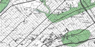
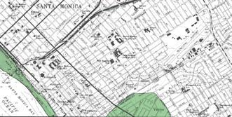
16 3 GUIDELINES FOR GEOTECHNICAL REPORTS Geotechnical work includes both engineering geology and geotechnical engineering. This section provides specific guidelines related to report content for various aspects of most geotechnical reports. 3.1 Geotechnical Reference Standards In general, all geotechnical and geologic reports shall comply with the most recent versions of appropriate standards, codes, and professional guidelines. The citations for some of the appropriate references are included in Appendix A. 3.2 Report Organization and Content All geotechnical reports shall include the following items, as appropriate for each project. Project Consultants determine the specific report format Purpose and Scope The report shall clearly identify the purpose and scope of the study Site Description Describe the existing site conditions including: Site Location, including address and cross streets. Site Topography. Site Drainage. Existing Structures & Improvements. Adjacent Properties, in particular, closely located structures, subterranean structures, and slopes that may affect or be affected by the proposed development Proposed Development Reports shall contain a description of the proposed development. The proposed developments shall be clearly shown on site plans, geologic maps, and cross-sections Previous Geotechnical Data All geotechnical data previously collected for the subject site and adjacent sites that are used to support geologic and geotechnical engineering interpretations shall be included within the report, included on the geologic map and appropriate cross sections, and properly referenced in the geotechnical report. Consultants shall perform a diligent search for previous data and discuss known geotechnical investigations for the site and adjacent sites and include copies of previous reports with the previously collected data (boring logs, laboratory data) for the site or used in the site assessment Clay Pit Areas The Safety Element identifies specific areas within the City where previous clay mining activity resulted in open pits. Clay pit areas are shown in Figure 2. Many of these pits, about 10 to 30 feet deep, were still open into the early 1960 s. Since the cessation of clay mining activities, many of the open pits have been backfilled, but may contain hazardous waste within the backfill. The potential hazards associated with the clay pit area include differential settlement, explosive gases, and hazardous wastes. These hazards shall be recognized and planned for during site exploration, and appropriate mitigation measures shall be Version
17 implemented for development of the site. Since the pit areas are relatively shallow, mitigation can sometimes be readily accomplished by removal of the uncertified fills and landfill debris and backfilled with suitable materials Field Exploration Describe the field exploration, methods of excavation, methods and type of sampling, provide exploration logs, and include dates of exploration. Geotechnical reports shall include logs of all geotechnical explorations (boring, test pit, and trench logs) on the site, including cone penetrometer data and results of other in situ testing. Each exploration point with a depth greater than 20 feet shall be identified with coordinates (longitude and latitude, expressed in decimal format) and elevation. For fault trenches, the end of each straight-line segment shall be identified with coordinates. Additional information that shall be shown on exploration logs or included within the report text includes: Names of the responsible field personnel. Dates of exploration. Exploration method/drill rig type (e.g., hollow-stem auger, bucket auger, wet rotary). Groundwater observations (indicate time of measurement). Sample Depths. Hammer (e.g., safety hammer) and sampler (e.g., SPT with or without liners, modified California sampler) details and method of hammer drop (e.g., automatic, cathead and rope with number of wraps) to convert measured sampler blow counts to an equivalent blow count associated with SPT with a delivered energy of 60% (N 60 ). Detail of Kelly bar weight and drop height (if applicable). Field (unmodified) sampler blow counts. Description of excavation backfill. Results of field tests (e.g. pocket penetrometer, vane shear). Results of soil density and moisture tests and percent fines. Exploration methods shall be sufficient in number and depth to evaluate site conditions, including the lateral and vertical variability in material properties, and acquire data to justify all conclusions and recommendations. In all cases, the depth of exploration shall extend deeper than the proposed foundations. Where applicable, the exploration program shall be coordinated between the Geotechnical Engineer and Engineering Geologist. Subsurface exploration shall be performed in areas most likely to reveal adverse geologic and soil conditions that could affect the proposed development or offsite properties due to the development on the subject site. Conditions to be evaluated include: Exploration and documentation of all geomorphic features that suggest the presence of landslides, mud and debris flows, faults, near-surface groundwater, and other possible adverse conditions. Descriptions of geologic conditions, including bedding, joints, shears, clay seams, fractures, and physical properties of all soils, alluvial deposits, colluvial deposits, weathered bedrock, bedrock, and other earthen materials encountered. Descriptions and locations of springs, artesian conditions, seeps, perched zones of groundwater, aquicludes, aquitards, and confined and unconfined aquifers. For all new construction projects and large additions, the following minimum exploration program is expected: Borings in flat, alluvial areas shall extend below a zone where increases in stress due to imposed loads will not negatively affect the performance of the site improvements and shall be sufficiently deep to evaluate hydrocollapse potential that may affect the proposed improvements, liquefaction potential, and the potential seismically induced settlement of the site. Version
18 Borings in hilly areas shall also be of sufficient depth to locate the upper and lower limits of weak zones potentially controlling slope stability. The factor of safety of a potential slip surface passing beneath the maximum boring depth shall exceed 1.5. In hillside areas, more than one boring will generally be necessary to fully evaluate the site for geologic conditions and slope stability. The ASCE-LA guidelines for mitigating landslide hazards provide additional information that shall be utilized when establishing the scope of the field exploration program. Sampling intervals shall be at 2- to 3-foot intervals in the upper 10 feet or in the upper 10 feet below cuts or basement levels and at five-foot intervals below or at changes in material types when changes occur more frequently than the above sampling intervals. Under the direct supervision of a registered geotechnical professional, qualified personnel shall log in detail all subsurface excavations. Geotechnical logs shall include descriptions of earth units, intervals sampled with uncorrected (field) blow counts, laboratory test results (where appropriate), and logs of the soils and/or geology. Downhole logging of geologic borings by an engineering geologist is expected in hillside areas for the detailed evaluation of geologic conditions under the site, unless safety issues preclude downhole logging. If downhole logging is not performed, then appropriately conservative assumptions regarding geologic structure and lithology shall be incorporated in the project. The method of side-wall preparation for downhole or trench logging shall be described in the report. For small additions, remodels, and limited construction projects not impacted by slope stability issues, exploration shall extend to a minimum depth of twice the width of proposed footings below the bottom of proposed footings (e.g. for a 24-inch wide footing, exploration shall extend to a minimum depth of 48 inches below the proposed footing), a depth of five feet, or extend into competent material, whichever is greater Cone Penetrometer Data Cone penetrometer (CPT) data, when obtained, shall include profiles of cone tip resistance, either sleeve resistance or friction ratio, and porewater pressure, when available. Interpreted results, such as soil type, estimated relative density, friction angle, or undrained shear strength of the soil, and equivalent sample blow counts shall be included also. The methodology for interpreting the CPT data shall be cited. The type and size of cone and penetration rate shall be documented. CPT data shall be substantiated by at least one adjacent soil boring (for every four CPTs) with samples analyzed at least for sampler blow counts and grain-size distribution and compared to interpreted CPT results Groundwater Conditions Groundwater conditions must be evaluated and discussed for the subject site. The term groundwater as used here refers to all subsurface water (i.e., perched water, seepage, acquifers). The report shall address how the proposed development may affect future groundwater conditions and how groundwater may affect the development. Highest anticipated or highest historic groundwater levels, whichever is greater, must be utilized for all analyses. As a minimum, the following items shall be addressed and incorporated in the groundwater assessment: Groundwater encountered during field exploration. Review of the published Highest Historic Groundwater Elevation figures published as part of the Seismic Hazard Evaluation Reports near Santa Monica. Groundwater data, including the current water level or piezometric head, seasonal changes along with historic high and low water tables, if available. Version
19 The effects of potential heavy rainfall (such as strong El Nino years). The effects of irrigation on groundwater levels. The potential for geotechnical hazards associated with groundwater (such as seepage, high groundwater, artesian conditions, springs). The effects of existing or proposed private wastewater disposal systems and dry wells (where applicable) Shoreline Erosion Geotechnical reports for beachfront properties shall provide recommendations to mitigate the potential for shoreline erosion Materials Testing Geotechnical reports shall contain sufficient in-situ and/or laboratory testing data to characterize the subsurface material(s) and to substantiate calculations from which conclusions and recommendations are derived. The report shall include descriptions of the sample preparation and testing procedures and reference applicable ASTM procedures. In general, laboratory procedures shall be selected that will be representative of the site conditions during and post site development from a geotechnical engineering perspective. In addition to the presentation of numerical data for all laboratory testing, plots or illustrations of laboratory data are required. Data plots shall be submitted as necessary to substantiate the Consultant s conclusions and recommendations. Numerical and graphical presentations of laboratory data that shall be included in the report are: Dry density and moisture content of all undisturbed samples. Compaction curves showing maximum dry density and optimum moisture content. Grain-size analyses (sieve and hydrometer) for representative samples. Consolidation tests for representative undisturbed samples and remolded samples to represent fill materials if newly placed compacted fill will support loads. Shear strength tests with plots consisting of normal stress versus shear resistance (failure envelope), normal stress versus shearing resistance if the normal stress is not constant during the shear test, and shear resistance versus displacement. Shear strength data points shall be shown for both peak and ultimate conditions. Shear tests samples are often soaked prior to testing. The degrees of saturation of these test specimens are typically of the order of 80 to 90%. Therefore, reference to the specimens being saturated should not be made routinely unless the data supports that description. Direct shear tests on partially saturated samples may grossly overestimate the cohesion that can be mobilized when the material becomes saturated in the field. This potential overestimation of the cohesion shall be considered when selecting shear strength parameters. The as-tested moisture content shall be reported for all strength testing. A study of direct shear tests on soil samples compacted to 90% relative compactions shows the magnitude of variation in measured strength that can occur in materials with the same group name or category (based on the Unified Soil Classification System, ASTM 2487) and compacted to a relative compaction of 90%. Categories are based on ASTM using the results of grain-size analyses, and all tests were performed by the same laboratory on soaked samples and at a displacement rate of inches/minute for the direct shear tests. The coefficient of variation (COV), the ratio of the standard deviation to the mean, of the ultimate cohesion varies from 0.7 to 1.8, and the coefficient of variation of the ultimate friction angle Version
20 varies from about 0.1 to 0.25 for given material category. For example, silty sand, with 77 direct shear tests, exhibited COVs of 0.98 for cohesion and 0.18 for friction angle. A study of formational materials typical of Southern California show similar range in the COVs of the ultimate cohesion, but larger COVs (0.2 to 0.4) of the ultimate friction angle for direct shear tests on relatively undisturbed, soaked samples. The larger COVs are probably, in part, due to greater ranges in grain-size for a given formational material. A comparison of upper and lower bound failure envelopes for the same material type and at the same site for a given formational material showed ratios of upper bound to lower bound ultimate cohesion to vary from 1.8 to 14 and the ratios of the ultimate friction angles varied from 1 to 2. The number of tests at a site varied from 4 to 9. The studies demonstrate significant variability of soil strength within a site for a given material classification, whether the material is natural or compacted fill. Therefore, the number of shear tests shall be appropriate to evaluate the variability of the strength for a given material and between material types encountered for the project. Direct shear tests shall be performed in accordance with ASTM procedures. When the Consultant uses a rate of shear displacement exceeding inches per minute, the Consultant shall provide adequate data to demonstrate that the rate is sufficiently slow for drained conditions (e.g., the time to failure exceeds 50 times the time for 50% consolidation). Such data may also be required when testing fine-grained soils, regardless of the rate of shear displacement used in the test. The rate of inches per minute is not and should not be taken as a code or City requirement for performing direct shear tests. This rate is only a cutoff rate that is used in the review process to determine in most, but not all, cases when data will be required by the Consultant to demonstrate that the rate of deformation is sufficiently slow for drained conditions. ASTM standards for direct shear tests limit the particle size to 10% of the diameter of the direct shear test specimen. When descriptions of samples or results of grain-size analyses indicate that particle sizes exceed 10% of the diameter of the direct shear box, the measured shear test results may be impacted by larger particle sizes. Grain-size analyses of the tested sample shall be performed when visual descriptions indicate the presence of larger sized particles to demonstrate that the maximum particle size of the material meets ASTM requirements. Alternatively, the Consultant shall split the tested sample along the failure surface and provide a visual description of the material along the failure surface to demonstrate that large particle sizes have not influenced the test results. The Consultant needs to address this issue and provide an appropriate discussion of the selection of shear strength parameters for the project that is supported by data not impacted by particle size. An adequate number of soil index tests shall be performed to characterize the expansive nature of the material. At a minimum, the near-surface soils or the material at the basement level shall be characterized with expansion index tests and preferably a weighted plasticity index. An adequate number of consolidation tests shall be performed to evaluate hydrocollapse potential as well as soil compressibility. Laboratory testing shall include both: (1) odometer tests in which hydrocollapse is simulated, and (2) appropriate soil index testing (e.g., grain-size, Atterberg Limits, dry density, and moisture content). When evaluating hydrocollapse potential, consideration shall extend to depths well below the zone of stress influence of the footings or below any fill, and tests shall be performed at pressures typical of the magnitude to be encountered under design conditions. A discussion regarding potential risks for hydrocollapse are provided in Section 3.5. If soft to firm clayey or silty soils are present and/or anticipated, adequate time-rate consolidation testing shall be performed. Laboratory testing to provide a preliminary evaluation of soil corrosivity shall be performed for projects, although single-family residences, and associated amenities such as garages, swimming pools and spas may be exempted if deemed appropriate by the Geotechnical Consultant. The chemical properties of soils can have deleterious effects on building materials resulting from chemical reactions and electro-chemical processes. Tests that can be performed to provide a preliminary evaluation of these potential hazards include ph, chloride and sulfate contents, and resistivity. Version
21 Tests to determine the R-value of potential subgrade materials should be performed when providing pavements sections. When pavement sections are based on presumed R-values, confirmation tests shall be performed during grading Geotechnical Analyses and Findings The Consultant shall describe their site characterization in terms of geology and soil properties used in the analyses, and relate this description or characterization to the laboratory and field results with appropriate discussion and rationale. The analyses performed and the technical findings shall be clearly described. At a minimum, the geotechnical report shall specifically address each of the following potential hazards: Seismic hazards (see Section 3.3 Seismic Hazard Evaluation). Slope stability, including mud and debris flows and rockfall hazards (see Section 3.4 Static Slope Stability). Hydrocollapse potential (see Section 3.5 Hydrocollapse). Expansive soil (see Section 3.6 Expansive Soils) Identification and Mitigation of Risks The Geotechnical Consultant shall describe, discuss, and evaluate all potential geotechnical hazards (seismic shaking, fault and ground rupture, liquefaction, lateral spreading and surface manifestation associated with liquefaction, seismically induced settlement, tsunami, seiche, expansive soils, hydrocollapse) and either state that such hazard is not present or provide appropriate mitigation measures. Discussions and evaluations of each potential geotechnical hazard and any proposed mitigation measures shall be adequately and clearly supported with geologic and geotechnical data and appropriate analyses to demonstrate that the Consultant has given adequate consideration to each geotechnical hazard and to provide information to the property owner as to which hazards are present and which hazards are not present at the subject site. See Sections , 3.3, 3.4, 3.5, and 3.6. The lack of discussion and evaluation of a particular hazard will not be taken by the Reviewer as a presumption that such hazard does not exist, even if in the opinion of the Reviewer a particular hazard is not present at a site. The Geotechnical Consultant must provide appropriate statements for each of the typical geotechnical hazards. Reports submitted without an evaluation and comments related to all potential hazards will require a response. Although the risks associated with some hazards cannot be totally eliminated, the risk shall be mitigated to a level of preventing structural collapse, injury, loss of life, or undue financial burden, and the report shall identify for the property owner the level of risk. Acceptable mitigation methods can include recommendations related to site improvement, site drainage, maintenance practices, structural design, and obtaining appropriate insurance. In situations where such hazards are not identified at the site, the report shall include statements to that effect and provide support for making such statements. For example, California Geological Survey (CGS) [formerly California Division of Mines and Geology, CDMG] seismic hazard maps could be cited for certain projects, as identified in Sections 3.3, 3.3.4, and 3.3.6, to support statements that liquefaction or seismically induced landslides are low risks. Another example, is using consolidation data from nearby sites to support statements that foundation settlement due to hydrocollapse potential is low risk for small projects where extensive laboratory testing of deeper materials is deemed unwarranted and there is no history of hydrocollapse problems in the area, provided the Geotechnical Consultant is of the opinion that such data is representative of the subject site and the risk is appropriately discussed (see comments below concerning hydrocollapse). Soil classification data (e.g., dry density, moisture content, degree of saturation, and soil type) can also be useful to support such statements concerning hydrocollapse potential. Version
22 Conclusions and Recommendations. All findings, conclusions, and recommendations shall be substantiated by data included within the report. Applicable regional published (and unpublished, if available) geologic reports, maps, aerial photographs, and other technical documents (e.g., geotechnical reports on file with the City) for the immediate area or subject property shall be reviewed and referenced. Site-specific field and/or laboratory data and appropriate analyses shall substantiate all recommendations and conclusions with appropriate discussion and comments. Where professional judgment is utilized to augment the data and analyses, a technical rationale shall be clearly and thoroughly discussed. Potentially hazardous geotechnical processes and site conditions must be disclosed. Additional comments, intended to serve as a guide to the Geotechnical Consultant as to items the Reviewers use when reviewing geotechnical recommendations, are included in Section Figures The following figures shall be included with each report, and all maps shall include a scale and north arrow: Site Location Map. A map with a scale and north arrow shall be provided for all projects that shows the site and surrounding area, encompassing a large enough area to easily and accurately locate the site on regional maps. Regional Geologic Map. Regional geological maps depict conditions that extend out further than the site geologic or geotechnical map. The site location shall be shown on all regional maps. Regional geological maps may be used to locate and generate geological cross-sections that extend offsite, especially where sites encroach into hillside areas. Seismic Hazard Map (for sites near liquefaction or landslide hazard zones and fault management zone). Copies of seismic hazard maps showing the site location are required for all sites located inside or within 500 feet of a Seismic Hazard or Fault Management Zone. The scale of the hazard map shall be such to clearly show the location of the site and the proximity to the hazard. Geotechnical Map (40-scale or less). A site geotechnical map depicting the site and immediate area surrounding the site to be developed is required for all projects. Geologic conditions shall be depicted on the site specific geotechnical map including: o Location of existing onsite structures and the location of closely located offsite structures that have potential to interact with the proposed development. o Location of the proposed improvements. o The location of all exploratory borings and trenches/test pits known to exist on the site. o The location of all geologic cross-sections. o Plotted geologic data from all subsurface excavations. o A geologic legend that clearly defines all contacts, symbols, lithologic units, and other relevant data shown on the map. The site-specific geologic/geotechnical map for projects with significant grading shall use an accurate topographic base map and a scale sufficient to clearly depict the details of the proposed development and geologic and soil conditions. The base map shall clearly indicate the map scale, true north, and who prepared the map. As mentioned earlier, a copy of the tract as-built geotechnical grading plan shall also be included (if available) when submitting reports for swimming pools and spas. Version
23 Geotechnical Cross Sections. Cross sections are required where natural, cut, or fill slope heights or basements, retaining walls, or temporary/permanent excavations exceeds 10 feet, or when an excavation extends below a 1(H):1(V) from adjacent foundations. For basement excavations, at least two sections traversing the building in orthogonal directions shall be provided. The crosssections shall depict interpreted geologic conditions underlying the site. Cross sections shall clearly show site boundary locations, location and size of all existing (including nearby offsite structures) and proposed structures, locations of all exploratory excavations, material contacts, intersections with other cross-sections, and the extent of proposed grading. Geologic data, including the measured and the highest anticipated groundwater conditions across sites in both flat, alluvial areas and hillside areas, shall be interpreted throughout the length of the section. Worst-case geologic and soil conditions (the most adverse conditions that can reasonably be expected given the field conditions and site history) must be illustrated. Historic high groundwater levels as well as current groundwater levels must also be shown on the crosssections. Geologic cross-sections shall extend from the top to the bottom of slopes, without regard for property lines. If offsite geologic conditions could influence a site, cross-sections shall be drawn to illustrate those conditions. This may occur on sites that encroach into hillside areas. Where a grading permit is required, the geotechnical report shall include a proposed grading plan showing existing and proposed contours from which an appropriate number of cross-sections shall be drawn Signatures of Registered Professionals All final reports must be signed and stamped by appropriately registered professionals. Reports in hilly areas and all reports that contain geologic interpretations or subsurface exploration of faulting must be signed by a certified engineering geologist References The report shall include a statement referring to the standards and specifications used for all field and laboratory procedures. Referenced materials shall also include: Literature and records cited and reviewed. Aerial photographs or images interpreted, listing the type, date, scale, source, and index numbers, etc. Compiled data, maps, or plates included or referenced. Other sources of information, including well records, personal communications, procedures, or other data sources Appendices Supporting information can be included in appendices, as needed Computer-Assisted Analyses Engineering analyses assisted by computer programs shall include reference information regarding the software used, methodology, and printouts of applicable input and output files. 3.3 Seismic Hazard Evaluation Geotechnical reports shall address all potential seismically induced hazards that may affect the subject Version
24 property and proposed development, and provide adequate mitigation measures (if necessary). While the Seismic Hazards Mapping Act defines residential project subject to the act as developments of four or more dwellings, the Act does not prohibit the City from establishing guidelines that are stricter than those established by Chapter 7.5 (Section 2624). The City will require geotechnical studies to evaluate seismic hazards for all projects in accordance with these guidelines. In accordance with the Seismic Hazards Mapping Act of 1990 (Sections 2690 through 2699 of the Public Resources Code), portions of the City are included in the Seismic Hazard Maps for the Venice, Topanga, and Beverly Hills Quadrangles. These maps, which are available for review at the City Building & Safety Department and the CGS website, delineate zones that may be subject to liquefaction and earthquakeinduced landslide hazard. The CGS has also published Seismic Hazard Evaluation reports to accompany these seismic hazard maps. The CGS seismic hazard maps are considered to supersede the seismic hazard maps in the 1994 City Safety Element. Seismic hazards shall be evaluated in full conformance with SP117A, Guidelines for Evaluating and Mitigating Seismic Hazards in California (CGS, 2008), the SCEC document, Recommended Procedures for Implementation of DMG Special Publication 117, Guidelines for Analyzing and Mitigating Liquefaction in California (SCEC, 1999), and the papers by Seed et al (2003), Idriss and Boulanger (2004), Boulanger and Idriss (2006), and Boulanger and Idriss (2007). Slope stability evaluation shall conform the guidelines published by ASCE-LA: Recommended Procedures for Implementation of DMG Special Publication 117, Guidelines for Analyzing and Mitigating Landslide Hazards in California, Organized Through the American Society of Civil Engineers, Los Angeles Section (ASCE-LA) and SP117A. For all projects within the, geotechnical reports shall include site-specific assessments of seismic hazards for each project. The degree of the assessment may vary with the project type, as explained in the following paragraphs. The fact that a project site is not located within a seismic hazard zone or Hazard Management Zone does not obviate the requirement that these hazards be discussed in the report. The seismic hazard evaluation shall include a site-specific description of the following: Regional tectonic setting. Location of major and regional fault traces. Distances from the site to faults within two miles of the site shall be based on appropriate geologic maps and not on fault locations determined by computer programs using the CGS fault database. Location of the various traces of the Santa Monica fault with respect to the site. The discussion of the location of the Santa Monica fault shall, at a minimum, refer to the City s Safety Element (1994). Location of the site relative to the Fault Hazard Management Zone established by the City for the Santa Monica fault (Safety Element, 1994). Fault-rupture and ground-rupture hazard evaluation. During the 1994 Northridge earthquake, a seismograph at the city hall building recorded a peak ground acceleration of 0.93g, based on CGS database. Attenuation relationships (1) Boore, Joyner, and Fumal (1997), (2) Bozorgnia, Campbell, and Niazi, (1999), (3) Campbell (1997), and (4) Sadigh, Chang, Egan, Makdisi, and Youngs (1997), using the mean plus one standard deviation, predict peak ground acceleration for the Northridge earthquake of between 0.27g and 0.34g. These predicted accelerations are well below the measured acceleration. Thus, care should be exercised when relying on accelerations using attenuation curves for Santa Monica. To demonstrate the potential magnitude of seismic shaking that has occurred in Santa Monica, a tabulation of recorded peak ground accelerations from nearby recording stations for major events Version
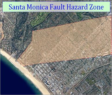
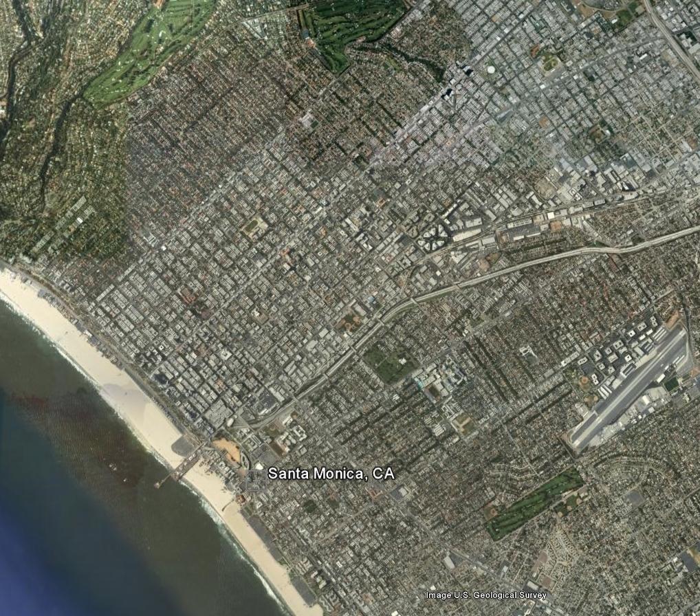
25 (currently only the Northridge event needs to be considered) affecting Santa Monica shall be summarized in tabular form. The tabulation shall include the identification of the recording station, peak ground acceleration, event, date of event, epicenter distances, magnitudes, and distance between recording stations and site. A map showing the locations of the recording stations and the site shall also be included. The tabulation and map are not required for singlefamily residences, but is required for multi-family projects and all municipal, commercial, and industrial projects. Evaluation of ground shaking potential (not required for single-family residences, unless the site is within a Seismic Hazard Zone, but is required for multi-family projects and all municipal, commercial, and industrial projects). Potential for liquefaction. Potential for lurching and topographic-related site effects. Potential for lateral spreading when the site is subject to liquefaction potential. Potential for surface manifestations when the site is subject to liquefaction potential. Potential for seismically induced settlement. Potential for earthquake-induced landsliding in hilly areas. Tsunami potential, for sites located within the zone of tsunami inundation on the maps published by California Emergency Management Agency (2010). Seiche potential Fault Rupture Hazards Data from recent fault investigations performed on the Santa Monica fault have demonstrated that the Santa Monica fault has likely been active within the Holocene period (within 11,000 years before present) (e.g. Dolan, J. F., Sieh, K., and Rockwell, T. K., 2000, Late Quaternary activity and seismic potential of the Santa Monica fault system, Los Angeles, California: GSA Bulletin, v. 112; no. 10; p ). Although the State of California has not zoned the Santa Monica fault as an Earthquake Fault Zone in accordance with the Alquist-Priolo Earthquake Fault Zoning Act of 1972, the City is currently treating the fault as active. The Safety Element of the General Plan established a Hazard Management Zone for the Santa Monica fault. The Hazard Management Zone includes all areas located between about 380 to nearly 500 feet north of the North branch and about 100 to nearly 600 feet south of the South Branch of the Santa Monica fault. The Hazard Management Zone map also indicates areas where researchers have mapped interpreted Strong and Weak geomorphic expressions of the Santa Monica fault. Leighton & Associates, Inc., March 30, 1994, published a detailed map of the Hazard Management Zone in the Technical Background Report to the Safety Element of the General Plan. A map showing the locations of the geomorphic expressions is available on the city s web site ( which is shown on Figure 2, and on the Online Property Information System web site for a specific address ( Fault trench studies are not required for sites within the fault hazard zone. Such sites, however, may still have a risk associated with ground rupture. The fact that a potential for ground rupture exists, does not mean that projects will be denied a permit, but the risk shall be identified and mitigation discussed. One element of the mitigation may be appropriate insurance for partial mitigation of the risk. If fault trenching, or alternative means, is performed to investigate the presence of a fault and the results demonstrate that the fault is present, new construction will not be permitted over the trace of the fault, and Version
26 an adequate setback must be established as mitigation. Minimum setback distances shall be established in accordance with the requirements of CGS Special Publication 42, Fault-Rupture Hazard Zones in California. Projects proposed for development within the Hazard Management Zone must, at a minimum, provide a qualitative evaluation of surface rupture hazard at the site. Such evaluation shall include a discussion of the: o o o Site location relative to the various mapped locations of the Santa Monica fault and geomorphic scarps. Recency of activity on the Santa Monica Fault Zone. Relative risk and consequences (potential damage) of fault rupture at the site if a fault were to extend below the proposed development and an earthquake occurred on that fault. o Measures that could be taken to assess the likelihood of a fault traversing the property. o Mitigation measures (e.g. insurance). When the city eliminated the requirement for fault trenching, the requirement of discussing the risk if a fault were to exist beneath the property and the other above issues were added to the guidelines to alert property owners of what the risk could be so they would be more informed when evaluating whether or not to explore the possibility of a fault s existence Ground Shaking Reports shall discuss the potential hazard from strong seismic ground shaking, where appropriate for quantitative hazard analyses (e.g., liquefaction and seismically induced settlement). Ground acceleration values shall be represented by the peak ground acceleration for either unweighted magnitude and the associated deaggregated magnitude or weighted magnitude (M = 7.5) associated with a 10% probability of exceedance in 50 years. Design accelerations and the probability of occurrence shall be discussed and justified in the report. Data shall be based on earthquake events on faults that may affect the site (i.e., faults within at least 40 miles of the site) using the CGS and USGS fault database. Any deviations from the CGS fault and USGS database shall be described and justified. Earlier versions of SP117 and CBC allowed ground accelerations to be based on CGS seismic hazard evaluation report maps, in lieu of a site-specific study. This is no longer allowed (SP117A), as the fault database and attenuation curves have been updated (Petersen, Frankel, Harmsen, Mueller, Haller, Wheeler, Wesson, Zeng, Boyd, Perkins, Luco, Field, Wills, and Rukstales; 2008). Ground accelerations shall be based on current versions of SP117 and CBC. Section of the CBC states that ground acceleration can be taken as the short-period design spectral acceleration (S DS ) divided by 2.5 in lieu of a site-specific study. Unfortunately this does not provide guidance for selecting the earthquake magnitude, which is required for liquefaction evaluations, seismically induced settlement, and lateral spreading evaluation. Therefore, a site-specific peak ground acceleration associated with a 10% probability of exceedance in 50 years and an unweighted magnitude shall be determined from a USGS web site, or an equivalent program (FRISK is no longer an acceptable program as the fault database and attenuation curves have not been updated) CBC Seismic Design Factors Seismic design factors shall be provided in accordance with the CBC and City policy. The 2007 CBC static-force procedure calls for the following seismic parameters to generate the response spectrum: the maximum spectral accelerations for 0.2 seconds (S S ) and one second (S 1 ) which are influenced by the site location, seismicity of the area, and the site class, and two site coefficients (F a, F v ), which depend on the spectral response accelerations and the site class. Thus, the only information that Version
27 the geotechnical consultant needs to provide is the site class. Knowing the site coordinates and the site class, the remaining items are easily determined by the structural or civil engineer from the web site of the USGS, Earthquakes Hazards Program. The software needed to determine the spectrum can be obtained from CBC Section states: When the soil properties are not known in sufficient detail to determine the site class, Site Class D shall be used unless the building official or geotechnical data determines that Site Class E or F soil is likely to be present at the site. If a site class other than D is recommended, the Consultant shall discuss and support the recommendation with site-specific data. A classification not consistent with the site-condition classification based on correlations between geologic units and the average S-wave velocity (V s ) in the upper 30 meters developed by the California Geological Survey, included within their statewide seismic hazard map and published in the SCEC Phase III report (Wills and others, 2000) will not be accepted without site-specific measurements. If the structural design is based on CBC dynamic lateral-force procedures, the Consultant shall provide an appropriate response spectrum curve and recommendations for vertical as well as horizontal acceleration. The vertical component is often taken as two-thirds of the horizontal component. Studies have shown, however, that the ratio of vertical-to-horizontal components is strongly dependent on oscillator period, source-to-site distance, and local site conditions (Bozorgnia, Campbell, and Niazi, 1999). The geotechnical report shall include a discussion of the rationale for selecting accelerations when developing the response spectra Liquefaction All reports shall address the potential for liquefaction to occur at the site (including lateral spread and surface manifestations) and identify whether the site is located within a Liquefaction Hazard Zone based upon the current Seismic Hazards Maps published by the CGS. The Project Consultant shall evaluate the liquefaction potential in general accordance with the Guidelines for Analyzing and Mitigating Liquefaction in California (Southern California Earthquake Center, March 1999), incorporating recent modifications (current SP117, Youd et al, 2001; Seed, Cetin, Moss, Kammerer, Wu, Pestana, Riemer, Sancio, Bray, Kayen, and Faris, 2003; Idriss and Boulanger, 2004; Boulanger and Idriss, 2006; Boulanger and Idriss, 2007). Deviations from the guideline shall be described and justified. These methods do allow for screening. If an adequate factor of safety against liquefaction cannot be demonstrated (factor of safety against liquefaction must exceed 1.25), and it is determined that the effects of liquefaction exceed tolerable levels, mitigation measures to minimize the effects (i.e., preventing structural collapse, injury, loss of life) shall be provided. In the case of one- and two-story, single-family residences not within a Liquefaction Hazard Zone, if the Consultant does not considered liquefaction to be a hazard at the site, then a rational basis for that conclusion shall be provided. A rational basis may consist of a site not being within a Liquefaction Hazard Zone and the Consultant being of and stating the opinion that the depth to groundwater, density and age of underlying materials, or other factors (all appropriately referenced), are sufficient to preclude the risk of liquefaction. Liquefaction studies are not required for swimming pools and spas, soft-story retrofit projects or small additions and remodel projects, but the potential for liquefaction must be discussed. If the site, however, is within a Liquefaction Hazard Zone, the report shall clearly inform the property owner of the risk, the potential consequences to the proposed improvements, and methods available to quantify the risk Seismically Induced Settlement Granular soils, in particular, are susceptible to settlement during seismic shaking, whether the soils liquefy or not, and the potential for seismically induced settlement to a depth of 50 feet shall be quantified Version
28 for all projects except small additions and remodels, swimming pools and spas, and repairs. For these exempted projects, quantitative analyses are not required, but a discussion of the risk shall be provided. Dense deposits underlie much of Santa Monica. For a magnitude 7.5 earthquake with a peak ground acceleration of 0.5g, the computed seismically induced settlement in a 50-foot thick, dense, dry, granular deposit with a SPT blow count (N 1 60 ) of 30 is less than 0.5 inches. The computed settlement reduces to about 0.25 inches if the blow counts are 40. If, however, the groundwater is at the surface, the computed seismically induced settlement is about 4.7 inches in a deposit with a SPT blow count of 30 to a depth of 50 feet, decreasing to about 0.5 inches when the blow counts increase to 35, and to a negligible amount if the blow counts are 40. If the groundwater is at a depth of 25 feet, the computed seismically induced settlement is about 0.5 inches in a deposit with a SPT blow count of 30 to a depth of 50 feet. When selecting the depths of borings to quantify seismically induced settlement to a depth of 50 feet, consideration can be given to geologic conditions at the site. It may be only necessary to extend the borings to a depth where the deeper soils are expected to be sufficiently dense, based on geology, exploratory data in the area, and experience, that the estimated seismically induced settlement to the depth explored plus the amount anticipated for materials between the depth explored and 50 feet, assuming the highest anticipated groundwater, is within tolerable amounts or adequately mitigated. The presentation of results within the geotechnical report shall clearly present the rationale and supporting data when sitespecific data is not determined to a depth of 50 feet. The fact that a site has been subjected to previous significant earthquakes does not preclude additional seismically induced settlement from occurring. As pointed out by Seed and Idriss (1967), Niigata was subjected to an earthquake of the same intensity as the 1964 earthquake about 130 years earlier. Yet some buildings settled more than 40 inches during the 1964 event. The conditions in Santa Monica differ from those in Niigata, but using the argument that seismically induced settlement will not occur due to having experienced previous shaking will not be accepted, by itself, as a reason for no risk due to seismically induced settlement Seismically Induced Slope Instability Seismically induced slope stability analyses for shallow and deep-seated (gross) failure are required for slopes identified on the CGS seismic hazard maps and on all fill and cut slopes without adverse bedding more than 25 feet high at gradients of 3(H):1(V) or steeper. Seismically induced slope stability shall be performed for all natural and cut slopes at gradients of 3(H):1(V) or steeper with adverse bedding. In hillside areas, the report shall also address the potential for rockfall and mud/debris flow. Slope stability evaluations shall conform with the guidelines published by ASCE-LA: Recommended Procedures for Implementation of DMG Special Publication 117, Guidelines for Analyzing and Mitigating Landslide Hazards in California, organized through the American Society of Civil Engineers, Los Angeles Section (ASCE-LA). Potential topographic effects, including ridge-top amplification and lurching, shall be addressed for areas with steep slopes. The ASCE-LA guideline as well as SP117A require that seismically induced slope stability be evaluated with a displacement criterion. Sometimes consultants use peak strength for seismically induced slope stability evaluation, using the argument that the higher deformation or strain rates for earthquake loading conditions result in higher shear strength resistance. Although true, the cyclic action can degrade the shear resistance. Both the rate effects and cyclic degradation effects need to be considered in the selection of shear strength used in the analyses. The work by Boulanger and Idriss (2007) may provide a framework to evaluate these effects. See the ASCE-LA guidelines for other considerations. Many of the comments for static slope stability are also pertinent to seismically induced slope section. See Section 3.4. Version
29 3.3.7 Tsunami A discussion of tsunami hazard shall be included in geotechnical reports for sites located within the zone of tsunami inundation on the maps published by California Emergency Management Agency (2010). For reference, the Safety Element of the General Plan (Section 3.2) includes a discussion of Tsunami hazards in the. 3.4 Static Slope Stability General Reports shall address the stability of slopes that may affect the site or that the proposed development may affect. Quantitative slope stability evaluations are required for sites on or immediately adjacent to natural, cut, and fill slopes where slope heights exceed 25 feet and the gradient is 3(H):1(V) or steeper or for natural and cut slopes with bedding that is detrimental to slope stability irrespective of the slope height. Slope stability evaluation shall conform with the guidelines published by ASCE-LA: Recommended Procedures for Implementation of DMG Special Publication 117, Guidelines for Analyzing and Mitigating Landslide Hazards in California, organized through the American Society of Civil Engineers, Los Angeles Section (ASCE-LA) and SP117A. Subsurface geologic and groundwater conditions must be evaluated and illustrated on geologic cross-sections and must be utilized by the geotechnical engineer for the slope stability analyses. If on-site wastewater or storm water disposal exists or is proposed, the slope stability analyses shall include the effects of the effluent plume on slope stability. All reports in hillside areas shall address the potential for surficial instability, debris/mudflow, rockfalls, and soil creep on all slopes that may affect the proposed development or be affected by the proposed development. Stability of slopes along access roads shall be addressed Geologic Interpretation Interpretation of geologic conditions shall be clearly explained and must be supported by adequate exploration and laboratory data. Part of the process in developing a geologic interpretation is explaining plausible models and eliminating models that may seem to be plausible but are flawed. Therefore, when the Project Geologist explains their interpretation, they must include comments and discussion to rule out other seemingly plausible interpretations of the data. Geologic cross sections shall clearly show an interpretation of the site stratigraphy across the section and not be limited to only the interpretation at exploration points. Interpretations shall include bedding, faults, material types, and landslides Shear Strength Selection for Slope Stability Evaluation The Geotechnical Consultant shall describe their selection of shear strength parameters for the various materials for use in slope stability analyses, including a discussion explaining the selection of strength parameters for site characterization and how the shear strength testing methods used are appropriate in modeling field conditions and long-term performance of the subject slope. Shear strengths sometimes used in stability analyses can be categorized as peak, ultimate, fully softened, and residual. The peak strength represents the maximum shear resistance on the stress-deformation (or strain) curve. The residual shear resistance is the shear strength at large displacements or strains when the material particles are aligned in the direction of shearing. The ultimate shear resistance for some materials is the same as the peak strength, but for other materials, generally those that experience dilative behavior, the ultimate strength is less than the peak strength but greater than the residual strength and is identified as the point on the stress-displacement (or strain) diagram where there is a reverse in its Version
30 curvature or an inflection point (Skempton, 1985). The reverse in curvature is associated with a zero volume change in a drained test or zero change in porewater pressure in an undrained test on a saturated sample with increasing displacement or strain. According to Sabatini, Bachus, Mayne, Schneider, and Zettler (2002), The fully softened strength is intermediate between the peak strength and the residual strength and there are no specific procedures to identify the fully softened strength. Conceptually, the fully softened strength is close in value to the peak strength of the same soil in a normally-consolidated condition. The ultimate strength and the fully softened strength, in general, are not the same. The fully softened shear strength is associated with a failure envelope having a zero or near zero cohesion. Therefore, the use of the term fully softened shear strength shall not be used unless it can be demonstrated that the shear strength represents that of a normally consolidated sample when the volume change is zero with increasing deformation. The design shear strength values shall be justified with laboratory test data, geologic descriptions and history, along with past performance history, if known, of similar materials. In short, this discussion shall include the rationale of why their selected strength parameters are appropriate for the site. Some of the items that need to be included or considered in such discussions are: Strengths utilized for design shall be no higher than the lowest computed using back calculation. Assumptions regarding pre-sliding topography and groundwater conditions at failure must be discussed and justified. If the calculated factor of safety for a landslide mass is above the value that existed at the time of failure, it shall be shown what changes have taken place to result in the safety factor increase. The literature is full of data on presumptive strength parameters for different material types. Great care, however, must be exercised when attempting to justify a selection of strength parameters by referring to such data. For example, presumptive strength parameters given for siltstone are generally for hard siltstone and may not be appropriate for softer siltstones encountered in this region. If use is made of such presumptive parameters to supplement on-site data, a convincing argument as to why such parameters may be appropriate for the subject site must be given before such parameters will be accepted. Multiple shear tests shall be performed for each project. The number of shear tests shall be appropriate to evaluate the variability of the strength for a given material and between material types encountered for the project. Multiple shear strength tests shall be provided for each material type. When limited strength data are obtained, appropriate conservatism should be used to select shear strength parameters for slope stability (see page 50 of the Recommended Procedures for Implementation of DMG Special Publication 117, Guidelines for Analyzing and Mitigating Landslide Hazards in California, June 2002). Ample site-specific data are required. The Geotechnical Consultant needs to provide a discussion to support their selection of shear strength parameters. The use of composite graphs of shear strength data of similar materials is useful when providing justification for the selected shear strength parameters for slope stability. Reliance is sometimes made on shear strength data in the Seismic Hazards Zone Reports. These strength data were obtained from a number of sources with the quality of sampling and testing varying between the sources. Today s standards differ from those at the time most of the data contained in the Seismic Zone Hazard Reports were obtained. Relying on data from these reports is not acceptable for a specific site. The criteria for strength selection, as described in the ASCE-LA Guideline, rely, in some cases, on the plasticity, as defined by the liquid limit. Although the ASCE-LA Guideline allows visual classifications to distinguish between levels of plasticity, laboratory test data will be required here. Version
31 Shear strength values higher than those obtained through site-specific laboratory testing will not be accepted. The material near bluffs may be more highly weathered and may have lower shear strengths than material more remote from the bluff. Evaluations of the stability of bluffs shall be based on shear strength parameters near the bluff and not remote from the bluff. Descriptions of the materials and mapping of the bluff shall be provided. Shear tests performed on samples taken adjacent to or on the bluff face from adjacent sites should be reviewed and discussed, if available, in addition to the mapping. A clear discussion and evaluation of the selected shear strength parameters, based on appropriate data, shall be included within the report. Direct shear tests do not always provide realistic strength values. Watry and Lade (2000) demonstrate the magnitude of scatter that can result with using the direct shear device to measure residual shear strength. Furthermore, bedding planes may not be parallel to the direction of shear in a direct shear device. The residual shear strength measured in the laboratory parallel to bedding is not necessarily the same as measured perpendicular to bedding (Mesri and Shahien, 2003). Correlations between liquid limit, percent clay fraction, and strength (fully softened and residual) by Stark, Choi, and McCone (2005) will be used during the review process to evaluate strength parameters (failure envelope) used by geotechnical consultants. Strength values used in analyses that exceed those obtained by this correlation must be justified. Therefore, results of grain-size analyses and Atterberg limits shall be submitted for samples with shear-strength test results. If the percent clay and liquid limit are determined after air-drying the specimens or the samples are well indurated, then the ball-milling corrections need to be applied to the measured percent clay and liquid limit. The ASCE/SCEC guidelines state: It is the judgment of the Committee that, based on the current state of knowledge, the residual strength friction angle from a drained test conducted at "normal" strain rates can be used as a first-order approximation of the residual strength friction angle under undrained and rapid loading conditions. As more data is collected and analyzed (e.g., Yoshimine, Kuwano, Kuwano, and Ishihara, 1999; Meehan, Boulanger, and Duncan, 2008), it is becoming apparent that this can result in underestimating the shear resistance on previously sheared surfaces, such as slickensides and landslide failure surfaces, under seismic conditions. For seismic loading conditions, the City will allow the use of residual strengths higher than those for static conditions. The geotechnical consultant must, however, provide justifications for any increases, supported with references and analyses. Shear strengths can and do vary within a site. As discussed in Section , to account for such potential variability, the number of shear tests shall be appropriate to evaluate the variability of the strength for a given material and between material types encountered for the project. The shear strength along bedding is typically less than the strength across bedding. To obtain the shear strength along bedding in a direct shear box, the technician must align the bedding plane in the direction of shear, and locate a bedding plane in the zone of shear. This is not an easy task, and thus it is difficult in many cases to obtain good quality measurements of along bedding strength. The Project Geotechnical Consultant must address this issue in his discussion of site shear-strength characterization. Shear strengths for proposed fill slopes shall be evaluated using samples mixed and remolded to represent anticipated field conditions. Confirming strength testing may be required during grading. Design shear strengths for fill slopes shall be consistent with anticipated long-term movements and obtained from samples that have been soaked in an effort to reach saturated conditions. If direct shear or triaxial shear testing is utilized to model the strength of jointed and fractured Version
32 bedrock masses, the design strengths shall be crosschecked with shear strengths obtained from the overall bedrock mass quality and be consistent with rock mechanics practice. When a material contains fractured bedrock, with abundant tectonic shears, both continuous and discontinuous, or discontinuities, such as slickensides and fissures, the in-situ strength will depend on the frequency and orientation of the discontinuities. The Consultant should provide sufficient data to characterize joint patterns likely to be present below the subject site, and at least a qualitative analysis of the following: Do well-defined joint sets exist that could either individually, collectively, or through their intersections act as planes of weakness along which translational, quasi-rotational, or wedge failures could occur? How might these joint sets either individually or through interaction with each other impact developments proposed in the shallow subsurface? These basic geometric considerations must be defined before an appropriate mode of failure can be defined for analysis and are best defined by a detailed discussion of observed joint patterns based on examination of many joints and joint sets both on- and off-site. Choice of appropriate shear strengths must consider the continuity of joints, the morphology of joints and asperities (planar, irregular, smooth, rough), the presence and nature of any joint linings. Direct shear tests should be completed that represent the materials likely to be present along potential failure surfaces. For example, it may be most appropriate to complete direct shear tests on samples that have been pre-cut to represent the strength along fractures or joints. In short, the Consultant needs to provide a detailed evaluation of the measured shear strengths and discuss how the impact of fractures and joints was taken into account when selecting the shear strength parameters for use in slope stability analyses, the mode of potential failure and in making design recommendations. See Section Impact of Defects on Shear Strength Selection The soil properties measured in the laboratory (e.g., failure envelope, as defined by cohesion, c, and friction angle, φ, or the modulus, E) may differ from the corresponding in situ or operational properties. Factors contributing to inaccuracies or shortcomings of laboratory measurements include: (1) disturbance due to stress release during sampling, (2) mechanical disturbances during sampling, handling, storing, and specimen preparation, (3) soil anisotropy, (4) relative magnitude of intermediate principal stress, (5) rotation of principal planes during shear, (6) rate of shearing, (7) cyclic loading, (8) strain softening, (9) initial in situ stresses, (10) specimen size, (11) calibration errors, and (12) limited testing of a statistically heterogeneous material. All these factors need to be taken into account when selecting shear strength parameters to characterize the site. The influence of these factors on the uncertainly in the material properties have been discussed in a number of papers (Lumb, 1966; Singh and Lee, 1970; Wu and Kraft, 1970; Schultze, 1971; Ray and Krizek, 1971; Fredlund and Dahlman, 1971; Yucemen, 1973; Kraft and Murff, 1975). One item that often is not fully addressed by geotechnical consultants and of significant importance is the influence of defects, such as fissures, slickensides and joints, on the shear strength that can be mobilized in the field compared to what is measured on small diameter test specimens. When the size of a specimen with a system of fissures randomly distributed is increased, the number of fissures included in the sample will increase, the probability of having fissures critically orientated to the applied stress system will increase, the probability of having larger fissures will increase, the probability of having large fissures critically orientated will increase, and the probability of coalescing adjacent defects in the proximity of the potential failure plane will increase. All these factors tend to decrease the applied stress required to rupture the specimen. The apparent strength will therefore decrease as the size Version
33 of the sample increases, and in the limit approach the strength of the soil mass. It is difficult to conceive that failure in the soil mass can take place along a continuous plane of weakness of considerable extent. The operational strength will therefore be higher than the fissure strength of the material, except for cases where failure is along a pre-existing slide surface in which the strength is reduced to, or close to, the residual strength of the material, failure is along predominant bedding planes or the weak layers are sandwiched between stronger strata, or progressive failure occurs in which strengths of portions of the potential sliding surface are successively reduced from the peak value to the residual state. Specimens for direct shear are only one-inch high and about 2.4 inches in diameter. Also, the specimens are confined in a relatively rigid ring when undergoing a shear test. The likelihood of a defect such as a fissure, regardless of its tightness or continuity, negatively affecting the measured strength is very small compared to the behavior in the field where there is less displacement constraint as would be provided by the ring in a laboratory test. Unconfined compressive strength, on samples larger than direct shear tests, by Bing Yen and Associates of siltstone and claystone at a Malibu site ranged between 800 to 4130 psf. Large variations in unconfined compressive strengths were also found by Bing Yen and Associates in sandstone (from 570 to 2980 psf). Some of this variation in unconfined compressive strength may be due to variations in moisture content, density, and grain-size composition, but it is likely that defects, such as shears, fissures, and slickensides, play a major role in the variation. The number or length of defects along a potential failure surface in the field, as a percentage, will likely exceed that in a small laboratory specimen, such as that of a direct shear specimen. Sampling of materials may result in the development of fractures, but that does not necessarily mean that such are present in the small specimens tested and therefore their impact on in situ strength may not have been taken into account in a laboratory direct shear test. The fractures, fissure, and slickensides do not have to coincide with the orientation of the potential failure plane in situ to negatively affect the strength that can be mobilized in situ, although the orientation will affect quantitatively the impact. Also, the number or length of defects along a potential failure surface in the field, as a percentage, will likely exceed that in a small laboratory specimen. The shear strength measured in the laboratory on small relatively and potentially intact samples may not be reflective of the strength that is mobilized in situ for materials that are fractured, even if not continuous. When fissures, fractures, and joints of the bedrock are of sufficient size and abundance for migration of precipitation, irrigation, and effluent into the bedrock, they certainly will have an impact on the shear strength that can be mobilized. It is difficult to accept a fracturing that provides for adequate effluent disposal, not to have a negative impact on the shear strength. Although guidelines provide for judgments in the selection of shear strength, all judgments need to be supported with appropriate references and not be contrary to the project data. Much of the research on shear strength of drained direct shear tests performed at university and national research laboratories, such as the Building Research Station or the Waterways Experiment Station, have been done at such rates of deformation corresponding to test durations of one-half to more than one day compared to less than one hour in most commercial laboratories. This results in lower measured shear strengths as well reducing some of the displacement constraint in the direct shear test. The intact and fissure strength provide the upper and lower bound values respectively of the strength that can be measured by any type of test on any sample size. Fractures, joints, and other defects will affect the strength of the bedrock that can be mobilized in the field, and result in a strength that is below that of a truly massive material or strength deduced from testing of laboratory specimen that may not contain defects due to the small size of the specimen. Studies have shown that when a material contains fractures, both continuous and discontinuous or discontinuities, such as slickensides and joints, the in-situ strength will depend on the frequency and orientation of the discontinuities. The strength in the soil or bedrock mass in the field, however, from the engineering point of view is the critical issue. Lo (1970) refers to this strength as the operational strength. Most of the work on the influence of defects on the measured shear strength as it varies with test specimen size has been done for undrained conditions, as the test times get very large for large-scale direct shear tests and drained conditions. Nevertheless, information gained Version
34 for undrained conditions is useful for gaining insight into the effects for drained conditions. The operational strength is influenced by the location, orientation, spacing or frequency or density of defects (Ward, Marsland, and Samuels, 1965; Lo, 1970; Wu, Williams, Lynch, and Kulatilake, 1987; and Jade and Sitharam, 2003). Regardless of the material being hard rock or softer soil, the studies show that the operational shear strength deceases as the density of defects increases. Wu, Williams, Lynch, and Kulatilake (1987) and Jade and Sitharam (2003) provide a means to quantify such defects. The ratio of the shear strength of an intact sample to the shear strength of a larger sample decreases with sample size in an exponential manner. Lo (1970) expresses the relationship in terms of the size of the failure surface, while Jade and Sitharam (2003) use a term called joint factor, which includes the density of the joints or defects, the inclination of the defect and the strength of the defect. Hoek and Brown (1988) and Hoek, Carranza-Torres, and Corkum (2002) also provide a quantitative method to evaluate the operational strength. If the Hoek-Brown model is used to determine shear strength or provide a comparison with laboratory measured strength on small samples, it should be recognized that one of the critical parameters is the compressive strength of the intact material. Thus, if the Hoek-Brown model is used, multiple unconfined compressive tests need to be obtained to provide a basis for the appropriate compressive strength. Sometimes geotechnical consultants estimate a compressive strength that approaches or exceeds that of concrete in materials that were drilled without the need of coring. It is not likely that a bucket auger will be able to excavate a material with a compressive strength of concrete. Thus, a much lower compressive strength than that for concrete would be appropriate for most materials if the Hoek-Brown criterion is used to represent the site. Even though some contend that the Hoek- Brown model is for hard rock, it can be an appropriate model to estimate the operational strength of softer fissured materials, if the input parameters are properly selected. In the case of a blue London clay for which adequate data are available, reasonable estimates of the operational strength parameters, representative of the curved failure envelope over a normal stress of 0.5 to 2.5 ksf, are obtained using the average measured intact compressive strength. There are three other parameters in addition to the unconfined compressive strength of the intact material that affect the results of the Hoek-Brown estimates of the operational strength. The selection of these three parameters, however, is somewhat subject and open to debate. Thus, the confidence level of using the Hoek-Brown model may be less than desirable when used for softer materials. Wu, Williams, Lynch, and Kulatilake (1987) found that measured peak and softened strengths, in terms of c (effective cohesion) and φ (effective friction angle), for 25-cm samples fell within one standard deviation of the strengths on 5-cm samples. The relatively small difference in this case may be due to the close spacing of the defects. Marsland and Butler (1967) compared drained cohesions and friction angles measured on triaxial samples with length to diameter ratios of 2 and diameters varying from 1.5 in., 3 in. to 5 in. The friction angles for all specimens were very close (a difference of 0.5 degree less for the larger samples), but the cohesion of the two larger samples were 65% of that for the smaller sample. A drained test on a 2-ft square shear box provided a cohesion that was slightly larger than measured on the two larger triaxial specimens and a friction angle that was a few degrees higher. A direct shear test may provide different strength parameters than a triaxial test even of the same size due to differences in the principal stress direction between the two test types as well as soil anisotropy and other factors, so it makes the comparison of test size a little less meaningful when results from different types of tests are compared in addition to the effect caused by heterogeneity differences between two samples. Nevertheless, most data show for either undrained or drained tests that shear strength decreases with an increase in specimen size for materials that contain defects. The rate of decrease, however, is affected by the orientation of the defects as well as the density or spacing and size of the defects. Variability in material or between samples of like material make any comparison based on very few tests of limited value. Bishop (1967) found for a 1.5-in.-diameter triaxial specimen that the drained cohesion was 45% of the Version
35 intact cohesion and the drained friction angle was 80% of that for an intact sample. Using Lo s (1970) model and the parameters for undrained tests would predict a strength for the 1.5-in.-diameter sample of 63% of the intact strength. If the drained intact cohesion and intact friction angle are used with the strength parameters along the fissure to obtain the ratio of the operational strength to the intact strength (keeping the other parameters as determined from the undrained tests), the computed strength for the 1.5- in.-diameter specimen is 58% (compared to the measured 45%) for the cohesion and 84% (compared to the measured 80%) for the friction angle. This is only one comparison, but it suggests for drained tests that the drained cohesion is reduced more than the drained friction angle, and the drained cohesion may be impacted more by defects than that for undrained strength. The question remains whether the constraints of the direct shear tests on small samples prevent the full impact of defects from being measured. Wu, Williams, Lynch, and Kulatilake (1987) used Skempton s residual factor (R) to determine the operational strength to cause failure. An R of 1 one corresponds to failure occurring at the residual strength, and an R of less than one corresponds to failure occurring at an operational strength between residual and peak strength. Slopes tended to fail with R values between 0.8 and 0.9 when the defect intensity was high and local zone of stress concentration were present. For the materials they studied, the maximum effect of defects was to reduce the operational shear strength to an R of 0.8. Thus, failure can occur before residual strength is reached. When failure occurs at an R value of less than one, the computed safety factor using the residual strength would be less than one. It is sometimes concluded by some geotechnical consultants that a computed safety factor of less than one with residual strength for a slope that is currently stable implies that residual strength is higher than what is being used. This may not be the case. Failure can occur before the residual strength occurs. With additional slope movement, the residual strength may be reached, but geometry changes result in a safety factor stabilizing at one. Skempton (1977) found for first-time slides in London clay that the operational effective strength envelope lies between the lower bound envelope for the strength on fissures (which is generally above the residual envelope) and the post-rupture strength for initially intact samples, which may be close to the ultimate strength. Stark and Eid (1997) found in a study of 14 first-time slides through stiff fissured clay with a liquid limit between 50 and 130% that the mobilized shear strength along the failure surface in first-time slides through stiff fissured clay can be lower than the fully softened shear strength and can be as low as the average between the fully softened and residual shear strengths. Geological factors, such as fissure spacing and bedding existence, loading conditions (cutting, fills, changes in groundwater), and zones of stress concentrations undoubtedly affect the operational strength. Although the fully softened and ultimate shear strength are not necessarily the same, the findings of Skempton (1977), Wu, Williams, Lynch, and Kulatilake (1987), and Stark and Eid (1997) are in general agreement as to the operational strength in comparison to other laboratory measures of shear strength. The geotechnical consultant needs to provide a discussion, supported with adequate data and reasonable interpretations, to justify their select of shear strength parameters and to specifically address how the presence of defects was taken into account in their selection of shear strength parameters used to characterize the site. The references used above as well as the paper by Mesri and Shahien (2003) are useful in developing a discussion to support how the presence of defects was taken into account in one s selection of shear strength parameters used in the analyses Soil Creep The potential effects of soil creep shall be addressed where any proposed structure is planned in close proximity to an existing fill slope, cut slope, or natural slope. The potential effects on the proposed development shall be evaluated and mitigation measures proposed, as appropriate, including appropriate setback recommendations. Version
36 3.4.6 Surficial Stability Surficial slope stability refers to slumping and sliding of near-surface sediments and is generally most critical during the rainy season or with excessive landscape watering. The assessment of surficial slope stability shall be based on analysis procedures for stability of an infinite slope with seepage parallel to the slope surface or an alternate failure mode that would produce the minimum factor of safety. The minimum acceptable depth of saturation for surficial stability evaluation shall be four (4) feet. All conclusions shall also be substantiated by appropriate analyses and data. Shear strengths shall be based on fully (100%) saturated samples tested at effective overburden pressures representative of the upper four feet of material. Additional comments concerning shear strengths and safety factors are provided in the ASCE-LA guidelines on slope stability. Surficial stability analyses shall be performed under rapid drawdown conditions where appropriate (e.g., for debris and detention basins) Slope Stability Analysis Gross stability includes rotational and translational deep-seated failures of slopes or portions of slopes existing within or outside of the proposed development. The following guidelines, in addition to those in the ASCE-LA document and SP117, shall be followed when evaluating slope stability: Stability shall be analyzed along cross-sections depicting the most adverse conditions (e.g. highest slope, adverse bedding planes, and steepest slope). Often analyses are required for different conditions or more than one cross section to demonstrate which condition is most adverse. The critical failure surfaces on each cross-section and for each mode of potential failure shall be identified, evaluated, and plotted on the large-scale cross section (i.e., coordinates of the potential slide planes within the lowest safety factors for each mode of failure (rotation, block) should be depicted on cross-sections utilized in the analyses). For all new construction of habitable structures, including single-family residences, guesthouses, studios, multi-family residential projects, commercial projects, and swimming pools, the minimum required long-term factor of safety is Rounding up computed safety factors is not allowed to meet the required minimum safety factors (e.g., is 1.49 not 1.50). Seismic slope stability evaluations shall follow SP117A and the ASCE-LA guidelines (an evaluation of seismically induced displacement). When areas are adjacent to or nearby existing landslides, the Consultant needs to discuss why the subject site has an acceptable computed safety factor against sliding while adjacent or nearby areas are potentially unstable or do not exhibit satisfactory safety. The minimum required factor of safety for temporary (during construction) excavations is If the computed factors of safety are less than the above minimums, mitigation measures will be required to bring the factor of safety up to the required level or the project may be re-designed to achieve the minimum factor of safety for static conditions and acceptable levels of computed displacement for seismic conditions. Long-term stability shall be analyzed using the highest known or anticipated groundwater level based upon a groundwater assessment performed under the requirements of Section The stability analyses model shall consider and incorporate all adverse geologic conditions such as joints, fractures, shears, faults, bedding planes, clay seams, gouge zones, clay beds, and landslide rupture surfaces. Circular and non-circular potential slip surfaces shall be utilized, as appropriate. Version
37 If units exhibit anisotropic strength conditions or planes of weakness that are inclined at angles ranging from nearly parallel to the slope to horizontal, safety factors for translational failure surfaces shall be calculated. Tension cracks and anticipated external loading shall be modeled, as appropriate. The most critical potential failure surface shall be well within the search limits. For the block-sliding mode, consideration shall include, but not be limited to, an evaluation of the potential failure mode passing through the toe of slope. See Figures 9.d through 9.1f of the ASCE-LA guidelines. 3.5 Hydrocollapse Hydrocollapse of subsurface materials is a decrease in volume (collapse) when these materials are subjected to water at a constant load. Materials prone to hydrocollapse include man-made fills, wind-laid deposits, and alluvial fan and mudflow sediments deposited during flash floods (Houston and Houston, 1997). The composition of materials most susceptible to hydrocollapse potential include silty to clayey sands that exhibit a degree of cementation. The primary sources of cementation are brittle, crystalline cementation, such as calcite, and cementation from high negative pore water pressures. The potential for hydrocollapse, which can occur well below the zone of influence of foundations, tends to increase with a decrease in degree of saturation, a decrease in dry density, an increase in fine content for sands to silty sands (clay content less than about 10%), and generally with an increase in consolidation pressures (there is a magnitude of stress, however, above which the magnitude of hydrocollapse begins to decrease with increasing stress). The potential for hydrocollapse is usually small when the degree of saturation exceeds about 60% to 70% for moderately dense soils, but as the degree of saturation decreases below 60%, the potential for hydrocollapse may increase (El-Ehwany and Houston, 1990; Houston and Houston, 1997). ASTM D5333 provides a collapse index to categorize the potential severity of hydrocollapse potential. This index, which is based on the hydrocollapse at a pressure of four ksf, ranges from none (0%), slight (0.1 to 2.0%), moderate (2.1 to 6.0%), moderately severe (6.1 to 10.0%), to severe (>10%). The majority of subsurface materials in Santa Monica fall in the none, slight, and moderate categories. Because of the cemented and contractive nature, collapsible soils are not usually as susceptible to disturbances caused by using samplers with large area ratios or by the vibrations of driven samplers. Data from debris flow deposits (personal communication with the author, 2002) have shown that sample disturbance can influence the measured compressibility of soils, but hydrocollapse potential may not always be appreciably affected by sample disturbance (Houston, Houston, and Spadola, 1988; Houston and El-Ehwany, 1991; Houston and Houston, 1997). On the other hand, weakly cemented materials are sensitive to sample disturbance. Smaller hydrocollpase was measured for driven samples than hand carved samples (personal communication with Robert Anderson, 2010). Although in some materials, sample disturbance may affect the measured hydrocollapse, sample disturbance will not be accepted, without supporting data and discussion, as a reason to dismiss data showing significant hydrocollapse potential. Hydrocollapse can result in significant foundation movements in materials that exhibit very low potential in the laboratory when water infiltrates to deep depths over a period of time. The need for mitigation of hydrocollapse risk should be based on the magnitude of potential total and differential settlements, not on a specified magnitude of strain, such as saying soils with some specified percent of hydrocollapse potential do not require mitigation. Laboratory evaluation of hydrocollapse potential needs to be performed at pressures typical of the magnitude to be encountered in the field. The potential settlement due to hydrocollapse is affected by the amount of potential collapse (which is impacted by the magnitude of stress for a given material) and the thickness of material affected as impacted by the potential of moisture infiltration. A well-compacted fill or competent natural deposit, for example, may exhibit a Version
38 small amount of hydrocollapse strain, but when integrated over a substantial thickness can result in substantial settlement. The risk of differential settlement is probably greater due to hydrocollapse in the upper materials, where the lateral extent of water infiltration due to leaks, for example, may be limited, than in deeper materials, where the zone of infiltration may extend to greater lateral dimensions, with the exception of canyon fills where the variation in the thickness of susceptible material can impact differential settlements. A reasonable expectation is to mitigate the hydrocollapse risk in the upper 10 to 20 feet to acceptable levels. Geotechnical reports, however, need to recognize the potential for risk in deeper materials, inform property owners of such risks, and recommend mitigating measures. If materials with a hydrocollapse potential are not wetted, hydrocollapse will not occur. Some of the major causes of infiltrating water are pipe breaks, excessive landscape watering, poor drainage, and rising groundwater levels. Acceptable measures to mitigate hydrocollapse risk include removal of the more susceptible material and recompaction, checking utility lines for leaks and promptly repairing such leaks, maintaining site drainage and drainage devices, and proper management of landscape watering to reduce the likelihood of water infiltrating deeper materials. Now that the has implemented their urban runoff mitigation plan to maximize on-site percolation of runoff, greater quantities of storm water will be infiltrating subsurface materials than in the past. The impact of implementing the urban runoff mitigation plan on developing hydrocollapse potential is uncertain, but environmental reasons for percolating on-site runoff have conflicting objectives with geotechnical concerns for satisfactory foundation performance. Geotechnical reports, nevertheless, need to include consideration of the urban runoff mitigation plan when addressing hydrocollapse potential, evaluating the associated risks, and informing property owners of ways to reduce such risks. 3.6 Expansive Soils Soils with an expansion index of more than 20 are considered expansive and may be subject to large volume changes with changes to the moisture content, causing foundation and slab uplift with increasing moisture and settlement with decreasing moisture. Mitigation measures must be provided for conditions with an expansion index of more than Settlement/Heave Reports shall analyze and estimate future total and differential movements of all footings, slabs, pipelines, and engineered fills supporting structures. The subsurface profiles used for settlement analysis shall be shown in cross-sections and be substantiated by subsurface data. Settlement analysis calculations shall be submitted. If professional judgment is used in addition to or to modify the calculated movement, justification or rationale upon which the judgment is made shall be provided. The estimated time for settlement to be 90% complete along with computations shall be provided where significant settlement is anticipated. Foundation and slab movements may result from settlement caused by seismic shaking and/or compression of supporting materials caused by live and dead loads of the foundations, settlement of compacted fill and underlying materials due to the weight of compacted fill, and swell or hydrocollapse of supporting materials if moisture infiltrates these materials. Vertical movement estimates shall, as a minimum, consider: Seismically induced settlement (See Section 3.3.5). Compression of the fill materials due to their own weight. Compression/consolidation of subsurface materials underlying fill. Version
39 Secondary consolidation, if it exists, of both fill and underlying subsurface materials. Hydrocollapse of fill and underlying subsurface materials (See Sections , , and 3.5). Settlement of foundations due to dead and live loads. Potential movement due to swelling (expansive) or shrinking soils (EI > 20). A settlement-monitoring program shall be implemented during and after construction in situations where the anticipated settlement of fill and underlying materials, due to the added weight of fill, exceeds one inch. Settlement monitoring shall consist of surface monuments and subsurface settlement plates. For additions, the Consultant needs to discuss the potential for and the potential impacts of differential settlement between the existing structure and the addition. 3.8 Geotechnical Recommendations The following comments are intended to serve as a guide to the Geotechnical Consultant as to items the Reviewers use when reviewing geotechnical recommendations. The list, however, is not intended to be exhaustive. A number of additional issues have been identified in the preceding sections. The Consultant must address each of the issues with supporting information. The Reviewers will not assume that unmentioned items are unimportant or do not need mitigation, even if in the opinion of the Reviewer such is the case. The Consultant has the responsibility to identify and discuss each issue, and if necessary provide mitigation measures Foundations Shallow Foundations [e.g., wall (continuous) and spread (pad) footings] Design of shallow foundations shall include the following recommendations that are applicable: Allowable bearing pressure. When the allowable bearing pressure exceeds 3000 psf, computations shall be provided to demonstrate that the computed safety factor equals or exceeds three for static loading conditions. Increases greater than one-third in bearing pressure for temporary (e.g., wind, seismic) loading will not be allowed unless it can be demonstrated that foundation movements under such loads will not cause unacceptable distress. Minimum footing embedment depth below lowest adjacent grade shall be at least 12 inches for one-story wood-frame structures and at least 18 inches for two-story wood-frame structures. A slab-on-grade floor with a roof above counts as one-story structure. A slab-on-grade floor with a second floor and roof above counts as a two-story structure. Minimum slope setback (CBC Section ). Estimated total and differential settlement (see Section 3.7). Resistance to lateral loads (passive soil resistance and/or base friction) specified as ultimate or allowable with recommended safety factors. Safety factors must equal or exceed 1.5. A onethird increase in resistance for temporary (e.g., wind, seismic) loading will not be allowed for passive and base friction resistances, unless the safety factors for static conditions exceed two. If the recommended passive or sliding soil resistance relies on a cohesive strength component, the shear strength parameters shall be based on drained tests at overburden pressures representative of the application (less than 250 psf for shallow footings) and on samples that have been soaked and have a degree of saturation of 100%. Cohesions measured on partially saturated (< 100%) samples will not be allowed to compute lateral resistances for shallow footings. Requirements for compacted fill pads or over-excavation and recompaction. Version
40 If existing footings will be subjected to additional loads, recommendations need to be provided for underpinning existing foundations, or geotechnical criteria need to be provided for accepting the existing foundations to carry additional loads Deep Foundations Design of deep foundations shall include each of the following that are applicable: Allowable vertical capacities (compression and uplift) as a function of foundation size (width, diameter, and depth), specify skin friction or end bearing, and safety factors used. Geotechnical safety factors must equal or exceed 3 for driven piles and the end bearing component of drilled shafts and 2 for shaft resistance of drilled shafts when computing allowable vertical capacities, unless load tests or pile driving analyses are performed to verify the results in which case lower safety factors may be used (ASCE, 1993; O Neil and Reese, 1999). Methods of analyses to evaluate axial capacity shall be appropriate for the type of pile being considered. For caissons, adhesion factors shall be no greater than one and adequately supported with references (O Neil and Reese, 1999; Kulhawy, 1991). O Neil and Reese (1999) have divided materials into five categories for purposes of computing shaft resistance of drilled shafts. Cohesive soils are fine-grained materials with undrained shear strengths, s u, < 5 ksf. Granular soils are coarse-grained materials with standard penetration sampler blow counts, N, < 50. Cohesive (fine-grained) materials with s u > 5 ksf and < 50 ksf are intermediate geomaterials. Cohessionless (coarse-grained) with N > 50 are intermediate geomaterials. Rock are materials with s u > 50 ksf. Methods are described by O Neil and Reese (1999) for computing the shaft resistance, as well as end bearing, for each material type. Other methodologies may be used, but the shaft resistance for any submerged coarse-grained materials shall be based on the submerged unit weight of the material. When the submerged unit weight is not used, as in the case of cohesive soil or rock, undrained shear strength parameters shall be used. The Consultant needs to clearly state and provide support (based on data, not opinions) for the category of the material that is supporting the piles, the strength and other properties used to characterize the materials for purposes of computing the axial capacity, and the method of analyses. Pile or caisson-tip elevations corresponding to minimum depths of embedment. Feasible pile and/or caisson types. Recommendations for installation of deep foundations. Potential for negative skin friction and effects on allowable vertical loads. Lateral resistance from earth pressures. The lateral resistance for piles is often taken as twice that for a wall to account for three-dimensional effects. Recommended allowable lateral loads shall be in accordance with Section of the CBC. Recommended lateral resistance of pile groups and the minimum pile spacing for the recommendations should be supported by analyses and recent references (e.g., Reese and Van Impe, 2001). Pile spacings of three-diameters (centerto-center) may be required before the piles act independently (e.g., Reese and Van Impe, 2001). The lateral resistance provided in the direction of the descending slope may be less than that for a level area. Calculations shall be provided to support recommendations for lateral resistance of piles. At shallow depths, the cohesive component has a strong influence on the computed equivalent fluid unit weight for lateral resistance. For piles that extend too much greater depths, the relative influence of the cohesive component decreases. Therefore, the computed lateral Version
41 resistance of piles shall be based on representative depths appropriate for the conditions. Forces acting on the piles and pile caps resulting from external loads, including lateral spreading, soil creep, surcharge from adjacent structures, or lateral load to achieve the appropriate factor of safety against slope failure. When the geotechnical consultant does not compute deflections of laterally loaded piles under design loads, the geotechnical report shall include recommendations for such computations by the structural/civil engineer. Adequate consideration must be given to the potential effects of a cracked section on the lateral behavior of concrete piles Soil-Pile Structure Interaction during Seismic Events The soil-pile-structure interaction during a seismic event is a complex phenomenon, even when the supporting soil is not subject to liquefaction. For example, the shear and moment in a pile increase with increasing pile stiffness, and amplification of the structural response is accentuated if the exciting frequency and the resonant frequencies of the soil deposit and structure are close to each other. As the pile stiffness increases more of the seismic load is transferred to the structure above, which in turn increase the dynamic load on the pile. Adding liquefaction to the mix further compounds the complexity of the interaction. Numerical models have been developed to gain insight into the interactions, and centrifugal testing in recent years has provided additional insights. Computed results with finite element analyses are generally in good agreement with results of simpler beam-on-winkler foundation if the soilpile springs and dashpots used to represent the soil-pile interaction effects are appropriately selected. A search of the ASCE database from 1975 to 2009 using soil-pile-structure interaction and seismic as the search terms yielded 47 papers beginning in 1980 with publications by Kagawa and Kraft (1980 and 1981). Most of the work is related to waterfront structures (piers and wharves) and bridges. The Kagawa and Kraft work was related to offshore, pile-supported structures. All of these studies demonstrate that the dynamic characteristics of the seismic event, local soil conditions, the structural characteristics of the piles, and the structural characteristics of the structure can have a significant impact on the results. Unfortunately software programs that have been developed for the numerical models are not readily available for commercial application, but a number of papers are available to provide insight. In addition, the results of centrifugal testing have confirmed the complexity of the interaction and also provide insight that can be used in developing design criterion. Liquefied soil and non-liquefied soil within and above a zone of liquefaction could impose lateral loads on the piles and pile cap. Loads from laterally spreading ground have been a major cause of damages to pile foundations in past earthquakes, particularly when a nonliquefied crust layer spreads laterally over underlying liquefied layers (Dobry and Abdoun, 2001). In the case of piles in soils that experience lateral spreading, Dobry and Abdoun (2001) state Both very rigid and more deformable foundation superstructure systems may be exposed to large lateral soil pressures, including especially passive pressures from nonliquefied shallow soil layer riding on top of the liquefied soil. and More damage tends to occur to piles when lateral movement is forced by a strong nonliquefied shallow soil layer than when the foundation is more free to move laterally and the forces acting on them are limited by the strength of the liquefied soil. The magnitude of lateral load that liquefied soil and non-liquefied soil in and above a zone of liquefaction impose on the piles and pile cap depends, among other factors, on the strength of the nonliquefied zone riding on top of the liquefied zone and the magnitude of lateral spread or the lateral movement of the soil relative to the pile and pile cap (Dobry, Abdoun, and O Rourke, 1996; Dobry and Abdoun, 2001; Dobry, Abdoun, O Rourke, and Goh, 2003; Abdoun, Dobry, O Rourke, and Goh, 2003; Boulanger, Kutter, Brandenberg, Singh, and Chang, 2003; Brandenberg, Boulanger, and Kutter, 2005). The lateral force can vary from near zero (if no lateral spread occurs) to that sufficient to correspond to the passive force in the zone above the liquefied zone plus the lateral force in the liquefied zone for large lateral displacements Version
42 (Brandenberg, Boulanger, Kutter, and Chang, 2007). The CBC requirements (considering only inertial loading) for computing the lateral load that gets transferred from the structure to the piles under seismic loading is considered acceptable at this point in time if the soils do not experience lateral spreading. When, however, the soils are subject to lateral spreading, additional lateral load (kinematic loading) is transferred to the piles and must be accounted for in the pile design to satisfy CBC requirements. The Project Geotechnical Consultant needs to provide analyses to support a lateral force that the piles and pile cap may be subject to if the site liquefies and experiences lateral spreading. The lateral loads need to be consistent with Dobry s findings and as well as those at the University of California at Davis (Boulanger, Kutter, Brandenberg, Singh, and Chang, 2003; Brandenberg, Boulanger, Kutter, and Chang, 2005, 2007, and 2007a). The results of these studies have been based on single piles as well as small groups of piles. Although the number of piles in these studies may differ from that supporting a structure on the coast, the findings lend themselves to develop reasonable levels of lateral loads that piles may be subjected to if lateral spreading occurs. To avoid the need for a costly mitigation solution, it is critical that the scope of the geotechnical study be sufficient to provide a realistic assessment of not only liquefaction potential, but also the potential for lateral spreading. Piles may inhibit the amount of lateral spread, and analyses shall be provided to demonstrate that the recommended lateral stabilizing force provided by the piles is consistent with the amount of predicted lateral spreading if lateral spreading occurs. CBC relies on ASCE 7-05 for design procedures. In particular, Chapter 11 of ASCE 7-05 deals with seismic design. ASCE 7-05 is undergoing modifications to clarify design requirements. Arulmoli, Johnson, Yin, Jaradat, and Mays (2008) describe the types of analyses needed and the geotechnical input required for seismic design of structures. Single-family structures in Santa Monica shall be considered of Moderate Importance with a performance level of Controlled and Repairable Damage. Furthermore, it should be recognized that simplified structural analyses may not provide cost-effective pile design when considering the lateral loads that must be supported under lateral spreading. Analyzing the foundation system as a bent where some of the moment is carried by the axial forces in piles may be more costly, but the resulting economies in the design, as reflected by construction costs, may more than offset the analyses cost. Also, ground modification may be a more economical alternative than using piles to mitigate lateral spreading Slab-on-Grade Construction All slab-on-grade design and construction, as a minimum, shall conform to CBC requirements. To provide a more competent foundation system for single-family residences supported with a slab-ongrade, the Consultant shall give consideration to recommending that the concrete for the slab and footings be poured as a monolithic unit and that a fiber-reinforced concrete be used to augment (not replace) steel reinforcement. Fiber reinforcement improves the tensile strength of concrete and reduces the likelihood of shrinkage cracks from developing Expansive Soils Specific foundation recommendations to mitigate the effect of expansive soils will be required for all foundations, slab-on-grade, and pools placed on soils with an expansion index value over Vapor Barrier Requirements Recommendations for vapor barriers shall conform to CBC requirements and be a minimum thickness of 10 mils. Version
43 3.8.4 Drainage The geotechnical report shall specify the need for and reasons why drainage and maintenance practices are required for satisfactory performance of foundations and slabs. Proper drainage and irrigation are important to reduce the potential for damaging ground/foundation movements due to hydrocollapse and soil expansion or shrinkage and for mitigating adverse effects due to erosion that may endanger the integrity of the graded site, foundations, or flatwork. All surface runoff must be carefully controlled and must remain a crucial element of site maintenance. The geotechnical report shall discuss and include, as appropriate, recommendations for (1) minimum slope gradients and distance for drainage away from foundations, (2) installing roof drains, areas drains, catch basins, and connecting lines, (3) drainage beneath raised floors, (4) managing landscape watering and maintenance of drainage devices, (5) inclusion of waterproofing or damp-proofing systems for walls and floors when dealing with subterranean space or when landscaping mounds are constructed against buildings, and (6) maintenance guidelines for property owners. Planter boxes located adjacent to foundations shall have a watertight base and be connected to an acceptable drainage system. Subdrains shall be installed below ponds and fountains Grading Recommendations Removal and Recompaction Grading recommendations shall include comments on clearing and grubbing, removal of old fill, debris, and abandoned tanks, wells, and septic systems. The report shall also include recommendations for the minimum depth and extent of the materials underlying the proposed foundations, including slab-on-grade construction, that need to be removed and recompacted. The report shall specify the minimum distance beyond the outside edge of shallow foundations for removal and recompaction, as determined by the engineer (typically 5 feet). The report shall provide recommendations for a foundation system that will mitigate or reduce the effects of excessive settlement or heave (e.g. to a level in which service related problems such as non-functioning doors and windows or excessively sloping slabs would not occur). Minimum removal depths referenced to the bottom elevation of the proposed foundations shall be specified and be consistent with the settlement estimates Compaction Requirements The report shall provide recommendations (specifications) for compacted fill addressing: Minimum relative compaction. Moisture conditioning requirements. Maximum particle size limits. Lift thickness. Mixing. Compacted fill shall be moisture conditioned to at or above optimum moisture content, and the minimum relative compaction requirement for structural fills, including slopes, is 90% of the laboratory maximum dry density as determined by ASTM D Subdrains Geotechnical reports shall include location and design specifications for all subdrains and back drains systems. The report shall include, but not be limited to outlet location, pipe size and material, gravel pack specifications, flow gradient, and filter fabric material. Additionally, need for cut-off walls, glued joints, vertical and horizontal drains and design specifications shall be included. Version
44 Cut/Fill Transition Areas Consideration shall be given to potential differential foundation movements for projects located on cut/fill transition areas. Foundations and utilities located in cut/fill transition areas and over variable thicknesses of fill may be subject to differential movements due to different stiffness characteristics and different hydrocollapse potential of the different supporting materials, under both static and seismic loads. Recommendations shall be provided to mitigate the risk of differential movements. Building pads located in cut/fill transition areas, for example, may be over-excavated to provide a relatively uniform thickness of fill below the bottom of the proposed footings. As a minimum, fill thickness beneath foundations in cut/fill lots shall be at least three feet, unless an alternative recommendation is justified on a site-specific basis. The geotechnical report shall include a recommendation that the structural engineer provide for structural mitigation in the form of extra structural reinforcement of slabs and footings based on a specified unsupported span length that may result for foundations on cut/fill lots Organic Content in Fills and Backfills All certified fills shall meet the provisions of the current edition of the City Building Code. The organic content percentage, as performed in accordance with ASTM D2974, Method C or D, shall not exceed two (2) percent Existing Fills Grading plans must show all existing fills on a project site and classify these fills as certified or uncertified, and also identify all buttress fills. For any grading involving cutting into an existing fill slope, the Project Consultant must characterize the fill slope and provide slope stability analysis for the proposed condition Fill Slopes The Consultant shall include recommendations for keyways, benching, and drainage details that conform to the City s Grading Ordinances/Codes Swimming Pools and Spas Recommendations for swimming pools and spas shall include lateral soil pressures acting on the walls, type of supporting materials, stability of temporary excavations, and the need for a subdrain and hydrostatic relief value Retaining Structures Standard Retaining Walls Standard retaining walls are those consisting of reinforced concrete or masonry block. Depending on the proposed development and site conditions, the report shall contain recommended earth pressures for proposed retaining structures. The design pressures shall consider and/or incorporate: Type of backfill (e.g., sand, silty sand, sandy clay, or clay) within the wedge defined by a 45- degree line from the heel of the retaining wall footing to the surface and recommended lateral pressures shall be compatible with the type of backfill within this zone, with higher pressures associated with soils having higher fine content. Using stability analyses to estimate lateral pressures can be misleading when non-zero cohesion values are used. The effective cohesion can reduce with time as the materials become wet, resulting in increases in lateral pressures. Thus, care needs to be exercised when selecting shear strength parameters for computing lateral pressures behind retaining structures, especially those backfilled with fine-grained soils. The Consultant shall provide a discussion of their selection of shear strength parameters to support Version
45 their recommendations. Existing and proposed surcharges (see also Section ). Factors that may affect the lateral loads such as slopes, adversely oriented geological features (e.g., bedding, joints, and fractures), lateral spreading. Wall restraining conditions. Higher lateral pressures and forces are expected for restrained retaining walls (e.g., basement walls) than retaining walls that are free to deflect. Backfill placement requirements, including temporary excessive equipment loading, if any. Appropriate shear strength for backfill materials, in-place materials, and structure support materials. Effects and pressures from expansive soils. Effects of creep-prone materials. In addition, the report shall contain the following design parameters: Allowable bearing pressures, coefficient of friction against sliding, passive resistance, and appropriate safety factors. Back drainage design and waterproofing or damp-proofing of subterranean walls and floors. Surface drainage requirements. For walls that retain slopes, the amount of freeboard to prevent sloughing over the wall shall be ascertained. The impact of debris or mudflow (earthflow) shall be considered in the design of walls that retain slopes that are subject to either surficial failure, debris flows, and/or mudflow. Calculations and/or assumptions shall be provided. Catchments for potential earthflows must be considered also Non-Standard Retaining Structures Non-Standard Retaining Structures are retaining walls not composed of reinforced concrete or masonry block. Examples of non-standard retaining walls include cribwalls, segmented-block walls, in situ reinforced walls, mechanically stabilized earth walls, and reinforced earth walls. In addition to the aforementioned requirements, the following items must also be considered for non-standard retaining structures: Analyses must be performed and included to show both the internal and external stability of the wall. All pertinent manufacturer s specifications and recommendations shall be included in the report. All walls shall contain appropriate backdrainage for the entire height of the wall. Walls shall be backfilled with free-draining clean sand or gravel, including backfill within the cells of cribwalls, unless it is demonstrated that alternatives will perform acceptably. No structures shall derive any support from non-standard retaining walls, unless it can be demonstrated that the vertical and lateral movements will be tolerable. A sufficient number of case histories may be required to substantiate the performance of the proposed walls under similar loading conditions. The zone or area behind walls containing reinforcement shall be shown on the as-built plans, and the area shall be marked with warning tape to reduce the likelihood of the reinforcement being torn by future digging. Version
46 Surcharge Behind Retaining Walls The Consultant shall evaluate the potential for vertical and lateral surcharge on retaining walls due to adjacent structures, footings, traffic load, or other causes. A surcharge source, such as a wall footing of an adjacent structure, located below a 1(H):1(V) plane could result in a sufficiently large lateral force on a retaining wall that should be accounted for in the design of the wall. Hence, using the 1(H):1(V) criterion to preclude the potential for lateral surcharge of retaining walls is not acceptable unless substantiated by appropriate analyses. Acceptable methods for determining lateral surcharge loads shall be based on method of elasticity, not on limit equilibrium methods, unless joints, adverse bedding, or fractures exist within the bedrock or soil mass being retained and would result in larger lateral surcharge loading Seismic Considerations Section of the 2007 CBC, which refers to basement walls and retaining wall of all heights, states that the geotechnical consultant needs to discuss and provide recommendations for lateral pressures on basement walls and all retaining walls due to earthquake motions. Section 1806A.1 requires that lateral pressures be provided for cantilever retaining walls higher than 12 feet. The current code is somewhat ambiguous in both defining when lateral earth pressures during seismic events must be considered and procedures for computing such pressures. LA County released a policy on the design of retaining walls in response to the new building code requirements and the County s previous recommendations in their 2006 manual. (See Building Code Manual policy , Design of Basement & Site Retaining Walls, dated ). This document requires that retaining wall seismic forces be specified in a geotechnical investigation for retaining walls. In brief, recommendations for seismic forces need to be based upon an on-site investigation based upon the following occupancies and wall heights: 1. For all occupancies except for Residential, Group R-3 occupancies--all basement walls and free-standing retaining walls over 8-feet in height need recommendations of static and seismic soil pressures based upon on-site investigations. 2. For Group R-3 occupancies--basement and retaining walls over 12-feet in height require recommendations of static and seismic soil pressures based upon on-site investigations. 3. Where earth pressures are not based upon an on-site investigations, recommended equivalent fluid pressures shall not be less than Table of Equivalent Fluid Weights in BCM policy , Art. 1, and the distribution (triangular for active pressures and rectangular for at-rest pressures) shall be as identified in the article. The White Paper, Seismic Increment of Active Earth Pressure (Lew, Hudson, Acosta and Elhassan, 2006) also provides guidance is providing recommendations for lateral earth pressures during seismic events. For projects in Santa Monica, the geotechnical consultant shall give consideration to both the LA County policy and that of the White Paper and provide specific recommendations for lateral earth pressures during seismic events and an explanation for the basis of these recommendations Shoring and Temporary Excavations Shoring systems are usually temporary supporting structures used to retain earth until the facility is completed. Shoring design parameters are used to determine the loads the retained soil and any other surcharge loads will exert on the shoring units and must be provided by the Geotechnical Consultant. The report shall evaluate the construction stability (temporary stability) during grading, foundation construction, and retaining wall excavations. All shoring shall comply with the following criteria, and the stability evaluation section of the report shall, at a minimum, include the following: A stability analysis model that considers and incorporates all applicable geologic discontinuities such as joints, shears, fractures, bedding planes, and faults. Version
47 Shear strengths utilized shall represent worst-case conditions anticipated at the time of excavation. Tension cracks and anticipated external loading shall be modeled, as appropriate. Construction stability shall be analyzed utilizing worst-case groundwater levels anticipated at the time of excavation. Construction stability shall be analyzed on all potential critical cross-sections. The critical failure surface on all cross-sections, shall be identified, evaluated, and considered in the design of the shoring system. All potential failure modes of anchored wall should be discussed and evaluated (Abating, Pass, and Bacchus, 1999). All temporary excavations shall possess a minimum factor of safety of If the factor of safety is less than 1.25, mitigation measures to bring the safety factor up to 1.25 will be required. Reports recommending shoring shall provide a geotechnical design including, but not limited to active and passive earth pressure magnitudes and lateral pressure distributions, type of shoring, the location and magnitude of any external loads that may affect the design and/or performance of the shoring systems, and minimum embedment for the restraint system. If a slot-cut type system is proposed, analysis will be required to demonstrate the stability of excavated slots. The resistance on the sides of the wedge shall be taken in a direction parallel to the critical failure plane (not in a horizontal direction). Slot cutting shall be the A/B/C method and not the A/B method. The factor of safety for slot-cut calculations decreases and then increases with increasing excavation height. Therefore, the calculations shall demonstrate that a shallower excavation does not have a lower safety factor than the plan excavation height. All trench shoring must conform to the provisions of the California Labor Code/State Construction Safety Orders. These regulations can be obtained from CAL-OSHA. Applicable requirements of CAL-OSHA shall be discussed and incorporated into the excavation stability assessment. If tiebacks are proposed, recommendations for performance and proof testing shall be included in the geotechnical report. The report shall address whether any construction dewatering will be necessary for the proposed excavations. The effects of the dewatering on adjacent existing structures/properties shall be evaluated, and mitigation measures shall be recommended as necessary. The report shall address the amount of anticipated deformation during construction and its effect on existing adjacent structures. The need for a pre-construction survey to document existing conditions, including those of adjacent structures, and for deformation monitoring during construction shall be addressed also (if applicable). If an excavation affects the stability of existing structures and/or off-site property, shoring must be designed and installed to eliminate the hazardous condition. The design must comply with all standards in this Guideline and must consider all factors such as slope stability, settlement, and creep. The soil strength parameters must be in accordance with the applicable criteria and shall not exceed the test values within the geotechnical report. Version
48 APPENDIX A References Reference Documents Leighton & Associates, Inc. (1994), Technical Background Report to the Safety Element of the City of Santa Monica General Plan, Project Number , March 30, CBA, Inc. (1995), Final Environmental Impact Report, Safety Element for, State Clearinghouse No , January General Reference Documents of Codes, Guidelines, and Standards American Society of Civil Engineers, Los Angeles Section (2002), Recommended Procedures for Implementation of DMG Special Publication 117 Guidelines for Analyzing and Mitigating Landslide Hazards in California, T. F. Blake (Chair), R. Hollingsworth, and J. Stewart (Editors), Southern California Earthquake Center, February 2002 (Updated June 2002). American Society for Testing and Materials (2010), Book of Standards, Construction, Soil and Rock (1), Vol [Use Most Recent Version]. Southern California Earthquake Center (1999), Recommended Procedures for Implementation of DMG Special Publication 117, Guidelines for Analyzing and Mitigating Liquefaction Hazards in California, Martin, G. R. and Lew, M. Co-Chairs and Editors, University of Southern California, March California Buildings Standards Commission (2008), 2007 California Building Code, Based on the 2006 International Building Code, Volumes 1 and 2 [Use Most Recent Version]. California Department of Conservation (2008), Guidelines for Evaluating and Mitigating Seismic Hazards in California, Special Publication 117A, California Geological Survey. California Department of Conservation (1998), General Guidelines for Reviewing Geologic Reports, DMG Note 41, Division of Mines and Geology. California Department of Conservation (1997), Fault-Rupture Hazard Zones in California, Special Publication 42, Division of Mines and Geology. California Department of Conservation (1986), Guidelines to Geologic/Seismic Reports, DMG Note 42, Division of Mines and Geology. California Department of Conservation (1986), Recommended Guidelines for Preparing Engineering Geologic Reports, DMG Note 44, Division of Mines and Geology, (Being Revised). California Department of Conservation (1986), Guidelines for Geologic/Seismic Considerations in Environmental Impact Reports, DMG Note 46, Division of Mines and Geology, (Being Revised). California Department of Conservation (2004), Checklists for the Review of Geologic/Seismic Reports for California Public Schools, Hospitals, and Essential Services Buildings, DMG Note 48, Division of Mines and Geology. California Department of Conservation (2002), Guidelines for Evaluating the Hazard of Surface Fault Rupture, DMG Note 49, Division of Mines and Geology. State Board of Registration for Geologists and Geophysicists (1998), Geologic Guidelines For Earthquake and/or Fault Hazards Reports. Version 1.6 A-1
49 State Board of Registration for Geologists and Geophysicists (1998), Guidelines For Engineering Geologic Reports. State Board of Registration for Geologist and Geophysicists (1998), Guidelines for Groundwater Investigation Report. ASFE, National Practice Guidelines for the Geotechnical Engineer of Record. Key Local Reference Documents Association of Engineering Geologists (AEG) Southern California Section (1982), Geologic Maps of the Santa Monica Mountains, Los Angles, California, complied by City of Los Angeles, California Department of Conservation (1986), State of California Special Studies Zones, Beverly Hills Quadrangle, Division of Mines and Geology, July 1, 1986, Scale 1:24,000. California Department of Conservation (1998), Seismic Hazard Evaluation of the Beverly Hills 7.5- minute Quadrangle, Los Angeles County, California, Open File Report 98-14, Division of Mines and Geology. California Department of Conservation (2000), Seismic Hazard Evaluation of the Topanga 7.5-Minute Quadrangle, Los Angeles County, California, Seismic Hazard Zone Report 01, Division of Mines and Geology. California Department of Conservation (2000), Seismic Hazard Evaluation of the Venice 7.5-Minute Quadrangle, Los Angeles County, California, Open File Report 98-27, Division of Mines and Geology, June 12, California Department of Conservation (1997), State of California Seismic Hazard Zones, Topanga Quadrangle, Division of Mines and Geology, April 7, California Department of Conservation (1999), State of California Seismic Hazard Zones, Beverly Hills Quadrangle, Division of Mines and Geology, March 25, California Department of Conservation (1999), State of California Seismic Hazard Zones, Venice Quadrangle, Division of Mines and Geology, March 25, California Emergency Management Agency (2010), Tsunami Inundation Maps for Emergency Planning, Beverly Hills Quadrangle, California Geologic Survey, March 1, California Emergency Management Agency (2010), Tsunami Inundation Maps for Emergency Planning, Topanga Quadrangle, California Geologic Survey, March 1, California Emergency Management Agency (2010), Tsunami Inundation Maps for Emergency Planning, Venice Quadrangle, California Geologic Survey, March 1, Dibblee, T. W. (1991), Geologic Map of the Beverly Hills and Van Nuys (South ½) Quadrangle, Los Angeles County, California, 1:24,000 scale, Dibblee Foundation, Santa Barbara, CA, Map DF-31. Dibblee, T. W. (1992), Geologic Map of the Topanga and Canoga Park (South ½) Quadrangle, Los Angeles County, California, 1:24,000 scale, Dibblee Foundation, Santa Barbara, CA, Map DF-35. Dolan, J. F., Sieh, K., and Rockwell, T. K. (2000), Late Quaternary Activity and Seismic Potential of the Santa Monica Fault System, Los Angeles, California, GSA Bulletin, Vol. 112, No. 10, p Hart, E. and Bryant, W. (1997), Fault Rupture Hazard Zones in California, Revised 1997, California Division of Mines and Geology. Hoots, H. W. (1930), Geology of the Eastern Part of the Santa Monica Mountains, Los Angeles County, California, U. S. Geological Survey Professional Paper 165-C. Version 1.6 A-2
50 Leighton and Associates, Inc. (1994), Technical Background Report to the Safety Element of the City of Santa Monica General Plan, Project No , March 30, Miscellaneous References Abating, P. J., Pass, D. G., and Bacchus, R. C. (1999), Geotechnical Engineering Circular No. 4, Ground Anchors and Anchored Systems, Federal Highway Administration, Office of Bridge Technology, Report Number FHWA-SA Abdoun, T., Dobry, R., O Rourke, T. D., and Goh, S. H. (2003), Pile Response to Lateral Spreads: Centrifuge Modeling, Journal Geotechnical and Geoenvironmental Engineering, ASCE, Vol. 129, No. 10, pp Arulmoli1, A. K., Johnson, G. S., Yin, P., Jaradat, O. A., and Mays, T. W. (2008), Geotechnical Considerations and Soil-Structure Interaction: Proposed ASCE Standards for Seismic Design of Piers and Wharves, Proceedings Geotechnical Earthquake Engineering and Soil Dynamics IV, ASCE, GSP 181. ASCE (1993), Technical Engineering and Design Guides as Adapted from the US Army Corps of Engineers, No. 1, Design of Pile Foundations. Bishop, A. W. (1966), The Strength of Soils as Engineering Materials, Geotechnique, Vol. 16, No. 2, pp Boore, D. M., Joyner, W. B., and Fumal, T. E. (1997), Equations for Estimating Horizontal Response Spectra and Peak Acceleration from Western North American Earthquakes: A Summary of Recent Work, Seismological Research Letters, Vol. 68, No. 1, pp Boulanger, R.W., Kutter, B.L., Brandenberg, S. J., Singh, P., and Chang, D. (2003), Pile Foundations in Liquefied and Laterally Spreading Ground: Centrifuge Experiments and Analyses. Report UCD/CGM-03/01, Center for Geotechnical Modeling, University of California, Davis, 205 pp. Boulanger, R. W., Idriss, I. M. (2006), Liquefaction Susceptibility Criteria for Silts and Clay, Journal Geotechnical and Geoenvironmental Engineering, ASCE, Vol. 132, No. 11, pp Boulanger, R. W., Idriss, I. M. (2007), Evaluation of Cyclic Softening in Silts and Clays, Journal Geotechnical and Geoenvironmental Engineering, ASCE, Vol. 133, No. 6, pp Bozorgnia, Y., Campbell, K. W., and Niazi, M. (1999), Vertical Ground Motion: Characteristics, Relationship with Horizontal Component, and Building Code Implications, Proceedings of the SMIP99 Seminar of Strong Motion Data, Oakland California, September 15, 1999, pp Brandenberg, S. J., Boulanger, R. W., and Kutter, B. L. (2005), Discussion of "Single Piles in Lateral Spreads: Field Bending Moment Evaluation," ASCE, Journal Geotechnical and Geoenvironmental Engineering, Vol. 131, No. 4, pp Brandenberg, S. J., Boulanger, R. W., Kutter, B. L., and Chang, D. (2005), Behavior of Pile Foundations in Laterally Spreading Ground during Centrifuge Tests," ASCE, Journal Geotechnical and Geoenvironmental Engineering, Vol. 133, No. 11, pp Brandenberg, S. J., Boulanger, R. W., Kutter, B. L., and Chang, D. (2007), Liquefaction-Induced Softening of Load Transfer Between Pile Groups and Laterally Spreading Crusts," ASCE, Journal Geotechnical and Geoenvironmental Engineering, Vol. 133, No. 1, pp Brandenberg, S. J., Boulanger, R. W., Kutter, B. L., and Chang, D. (2007a), Static Pushover Analyses of Pile Groups in Liquefied and Laterally Spreading Ground in Centrifuge Tests," ASCE, Journal Geotechnical and Geoenvironmental Engineering, Vol. 133, No. 9, pp Version 1.6 A-3
51 Bray, Jonathan D. (2001). Developing Mitigation Measures for the Hazards Associated with Earthquake Surface Fault Rupture, Workshop on Seismic Fault-induced Failures- Possible Remedies for Damage to Urban Facilities, Research Project 2000, Grant-in-Aid for Scientific Research (No ), Japan Society for the Promotion of Science, Workshop Leader, Kazuo Konagai, University of Tokyo, Japan, pp , January , 2001 (Invited Paper). (AEG Southern California Section website). Burland, J. B. (1990), On the Compressibility and Shear Strength of Natural Clays, Geotechnique, Vol. 40, No. 3, pp Campbell, K. W. (1997), Empirical Near-Source Attenuation Relationships for Horizontal and Vertical Components of Peak Ground Acceleration, Peak Ground Velocity, and Pseudo-Absolute Acceleration Response Spectra, Seismological Research Letters, Vol. 68, No. 1, January/February, pp Chandler, R. J. (1984), Recent European Experience of Landslides in Heavily Overconsolidated Clays and Soft Rocks, Proceedings, Fourth International Symposium on Landslides, Canadian Geotechnical Society, Toronto, Vol. 1, pp Chang, D. Boulanger, R. W., and Kutter, B. L. (2005), Dynamic Analyses of Soil-Pile-Structure Interaction in Laterally Spreading Ground During Earthquake Shaking, Proceedings, Seismic Performance and Simulation of Pile Foundations in Liquefied and Laterally Spreading Ground, Geotechnical Special Publication No. 145, University of California, Davis, California, March 16 18, 2005, pp County of Los Angeles (2008), Design of Basement & Site Retaining Walls, Building Code Manual Policy , Article 1, Department of Public Works, July 21, County of Los Angeles (2006), Manual for Preparation of Geotechnical Reports, Department of Public Works, December, Dobry, R. and Abdoun, T. (2001), Recent Studies on Seismic Centrifuge Modeling of Liquefaction and Its Effect on Deep Foundations, Proceedings, Fourth International Conference on Recent Advances in Geotechnical Earthquake Engineering and Soil Dynamics, San Diego, March 26 31, 2001, pp Dobry, R., Abdoun, T., and O Rourke, T. D. (1996), Evaluation of Pile Response Due to Liquefaction- Induced Lateral Spreading of the Ground, Proceedings, Fourth Caltrans Seismic Research Workshop, Sacramento, July 9 11, Dobry, R., Abdoun, T., O'Rourke, T. D., and Goh, S. H. (2005), Closure, Single Piles in Lateral Spreads: Field Bending Moment Evaluation, ASCE, Journal Geotechnical and Geoenvironmental Engineering, Vol. 131, No. 4, pp Dobry, R., Abdoun, T., O Rourke, T. D., and Goh, S. H. (2003), Single Piles in Lateral Spreads: Field Bending Moment Evaluation, Journal Geotechnical and Geoenvironmental Engineering, ASCE, Vol. 129, No. 10, pp EQE International (1995), Seismic Design Spectra for Seventeen Municipal Structures in the City of Santa Monica, California, May Fredlund, D. G. and Dahlman, A. E. (1971), Statistical Geotechnical Properties of Glacial Lake Edmonton Sediments, Proceedings, Conference on Applications of Statistics and Probability to Soil and Structural Engineering, University of Hong Kong, September. Hoek, E. and Brown, E. T. (1988), The Hoek-Brown Failure Criterion A 1988 Update, Proceedings 15 th Canadian Rock Mechanics Symposium, University of Toronto, Canada. Hoek, E., Carranza-Torres, C., and Corkum, B. (2002), Hoek-Brown Failure Criterion 2002 Edition, available at RocScience.com. Version 1.6 A-4
52 Houston, S. L. and El-Ehwany. M. (1991), Sample Disturbance of Cemented Collapsible Soils, Journal Geotechnical Engineering Division, ASCE, Vol. 117, No. 5, pp Houston, S. L. and Houston, W. N. (1997), Collapsible Soils Engineering, Proceedings, Unsaturated Soil Engineering Practice, ASCE, Geotechnical Special Publication No. 68, pp Houston, S. L., Houston, W. N., and Spadola, D. J. (1988), Prediction of Field Collapse of Soils Due to Wetting, Journal Geotechnical Engineering Division, ASCE, Vol. 114, No. 1, pp Idriss, I. M., Boulanger, R. W. (2004), Semi-Empirical Procedures for Evaluating Liquefaction Potential During Earthquakes, Invited Paper 11th SDEE and 3rd ICEGE, University of California, Berkeley, Jade, S. and Sitharam, T. G. (2003), Characterization of Strength and Deformation of Jointed Rock Mass Based on Statistical Analysis, International Journal of Geomechancis, ASCE, Vol. 3, No. 1, pp Kagawa, T. (1992), Effects of Liquefaction on Lateral Pile Responses, ASCE, Proceedings, Piles Under Dynamic Loads, GSP 34, pp Kagawa, T. and Kraft, L. M., Jr. (1980), Seismic p-y Responses of Flexible Piles, Journal, Geotechnical Engineering Division, ASCE, Vol. 106, No. GT8, August, 1980, pp Kagawa, T. and Kraft, L. M., Jr. (1981), Lateral Pile Response During Earthquakes, Journal, Geotechnical Engineering Division, ASCE, Vol. 107, No. GT12, pp Kraft, L. M., Jr. and Murff, J. D. (1975), A Probabilistic Investigation of Foundation Design for Offshore Gravity Structures, Proceedings, Seventh Offshore Technology Conference, Houston, TX, May 5-8, Vol. 3, pp Kulhawy, F. H. (1991), Drilled Shaft Foundations, Chapter 14, Foundation Engineering Handbook, Second Edition, Edited by H-Y Fang, Van Nostrand Reinhold, New York, pp Lew, M., Hudson, M. B., Acosta, J. A., and Elhassan, R. (2006), White Paper on Seismic Increment of Active Earth Pressure, PEER-BART/VTA Workshop on Seismically Induced Earth Pressures, June 8, Lo, K. Y. (1970), The Operational Strength of Fissured Clay, Geotechnique, Vol.20, No. 1, pp Lumb, P. (1966), The Variability of Natural Soils, Canadian Geotechnical Journal, Vol. 3, No. 2, pp Meehan, C. L., Boulanger, R. W., and Duncan, J. M. (2008), Dynamic Centrifuge Testing of Slickensided Shear Surfaces, ASCE, Journal Geotechnical and Geoenvironmental Engineering, Vol. 134, No. 8, pp Mesri, G. and Shahien, M. (2003), Residual Shear Strength Mobilized in First-Time Slope, Journal Geotechnical and Geoenvironmental Engineering, ASCE, Vol. 129, No. 1, pp Naval Facilities Engineering Command (1986), Foundations and Earth Structures, Design Manual 7.2, May O Neil, M. W. and Reese, L. C. (1999), Drilled Shafts: Construction Procedures and Design Methods, Federal Highway Administration, Report Number FHWA-IF , August Petersen, M. D., Frankel, A. D., Harmsen, S. C., Mueller, C. S., Haller, K. M., Wheeler, R. L., Wesson, R. L., Zeng, Y., Boyd, O. S., Perkins, D. M., Luco, N., Field, E. H., Wills, C. J., and Rukstales, K. S., (2008),Documentation for the 2008 Update of the United States National Seismic Hazard Maps, Open-File Report , U. S. Department of the Interior, U.S. Geological Survey. Version 1.6 A-5
53 Ray, J. N. and Krizek, R. J. (1971), Estimation of the Mean for Soil Properties, Proceedings, Conference on Applications of Statistics and Probability to Soil and Structural Engineering, University of Hong Kong, September. Reese, L. C. and Van Impe, W. F. (2001), Single Piles and Pile Groups Under Lateral Loading, A. A. Balkema, Rotterdam, Netherlands. Sabatini, P.J., Bachus, R.C., Mayne, P.W., Schneider, J.A., and Zettler, T.E. (2002), Geotechnical Engineering Circular No. 5, Evaluation of Soil and Rock Properties, Report Number FHWA-IF , April Sadigh, K., Chang, C. Y., Egan, J. A., Makdisi, F., and Youngs, R. R. (1997), Attenuation Relationships for Shallow Crustal Earthquakes Based on California Strong Motion Data, Seismological Research Letters, Vol. 68, No. 1, January/February, pp Schultze, E. (1971), Frequency Distributions and Correlations of Soil Properties, Proceedings, Conference on Applications of Statistics and Probability to Soil and Structural Engineering, University of Hong Kong, September. Seed, R.B., Cetin, K. O., Moss, R. E. S., Kammerer, A. M., Wu, J., Pestana, J. M., Riemer, M. F., Sancio, R.B., Bray, J.D., Kayen, R. E., and Faris, A. (2003), Recent Advances in Soil Liquefaction Engineering: A Unified and Consistent Framework, Annual ASCE Los Angeles Geotechnical Spring Seminar, Keynote Presentation, H.M.S. Queen Mary, Long Beach, California, April 30, Seed, H. B. and Idriss, I. M. (1967), Analysis of Soil Liquefaction: Niigata Earthquake, Journal Soil Mechanics and Foundations Division, ASCE, Vol. 93, No. SM3, pp Siding, K., Chang, C. Y., Egan, J. A., Makdisi, F., and Youngs, R. R. (1997), Attenuation Relationships for Shallow Crustal Earthquakes Based on California Strong Motion Data, Seismological Research Letters, Vol. 68, No. 1, January/February, pp Singh, A. and Lee, K. L. (1970), Variability in Soil Parameters, Proceedings, Eighth Annual Conference on Geotechnical and Soil Engineering, Idaho. Skempton, A. W. and Hutchinson, J. N. (1969), Stability of Natural Slopes and Embankment Foundations, Proceedings, Seventh International Conference on Soil Mechanics and Foundation Engineering, Mexico City, pp Skempton, A. W. and Petley, D. J. (1967), The Strength Along Structural Discontinuities in Stiff Clays, Proceedings, Geotechnical Conference on Shear Strength Properties of Natural Soils and Rocks, Oslo, Vol. 2, pp Stark, T. D., Choi, H., and McCone, D. S. (2005), Drained Shear Strength Parameters for Analysis of Landslides, Journal of Geotechnical and Geoenvironmental Engineering, ASCE, Vol. 131, No. 5, pp Stark, T. D. and Eid, H. T. (1997), Slope Stability Analyses in Stiff Fissured Clays, Journal of Geotechnical and Geoenvironmental Engineering, ASCE, Vol. 123, No. 4, pp Stark, T. D. and McCone, D. S. (2002), Drained Residual and Fully Softened Shear Strength for Slope Stability Analyses, Journal of Geotechnical and Geoenvironmental Engineering, ASCE, Submitted for publication. [Correlations available in ASCE-LA slope stability guidelines]. Stark, T. D., Choi, H., and McCone, D. S. (2005), Drained Shear Strength Parameters for Analysis of Landslides, Journal of Geotechnical and Geoenvironmental Engineering, ASCE, Vol. 131, No. 5, pp Turner K. A. and Schuster, R. L. [Editors] (1996), Landslides Investigation and Mitigation, Special Report 247, Transportation Research Board, National Research Council. Version 1.6 A-6
54 Ward, W. H., Marsland, A., and Samuels, S. G. (1965), Properties of London Clay at the Ashford Common Shaft: In Situ and Undrained Strength Tests, Geotechnique, Vol. 15, No. 4, pp Watry, S. M. and Lade, P. V. (2000), Residual Shear Strengths of Bentonites on Palos Verdes Peninsula, California, Slope Stability 2000, Proceedings at Geo-Denver 2000, Geo-Institute of ASCE, Griffith, D. V, Fenton, G. A., and Martin, T. R. editors, Denver Colorado, August 5 8, 2000, pp Wills, C.J., Petersen, M., Bryant, W.A., Reichle, M., Saucedo, G.J., Tan, S., Taylor, G., Treiman, J. (2000), A Site-Conditions Map for California Based on Geology and Shear-Wave Velocity, Bulletin of the Seismological Society of America, Vol. 90, pp Wu, T. H. and Kraft, L. M., Jr. (1970), Safety Analysis of Slopes, Journal of the Soil Mechanics and Foundations Division, ASCE, Vol. 96, No. SM2, pp Wu, T. H., Williams, R. L., Lynch, J. E., and Kulatilake, P. H. S. W. (1987), Stability of Slopes in Red Conemaugh Shale in Ohio, Journal Geotechnical Engineering, ASCE, Vol. 113, No. 3, pp Yoshimine, M., Kuwano, R., Kuwano, J., and Ishihara, K. (1999) Dynamic Properties of Fine-Grained Soils in Presheared Sliding Surfaces, Slope Stability Engineering, Vol. 1, A. Balkema, Rotterdam, Japan, pp Yucemen, M. S. (1973), A Probabilistic Study of Safety and Design of Earth Slopes, Ph. D. Dissertation, University of Illinois at Urbana-Champaign, 205 pp. Youd, T. L., Idriss, I. M., Andrus, R. D., Arango, I., Castro, G., Christian. J. T., Dobry, R., Finn, W. D., Harder, Jr., L. F., Hynes, M. E., Ishihara, K., Koester, J. P., Liao, S. C., Marchuson, III, W. F., Martin, G. R., Mitchell, J. K., Moriwaki, Y., Power, M. S., Robertson, P. K., Seed, R. B., and Stokoe, II, K. H. (2001), Liquefaction Resistance of Soils: Summary Report from the 1996 NCEER and 1998 NCEER/NSF Workshop on Evaluation of Liquefaction Resistance of Soils, Journal of Geotechnical and Geoenvironmental Engineering, ASCE, Vol. 127, No. 10, pp Zhang, G., Robertson, P.K., Brachman, R.W.I. (2002), Estimating Liquefaction-Induced Ground Settlements from CPT for Level Ground, Canadian Geotechnical Journal, Volume 39, pp Note: California Division of Mines and Geology (CDMG) is now California Geological Survey (CGS). DMG Notes, for example will become CGS Notes when republished. Version 1.6 A-7


55 Fault Hazard Management Zone 1. A discussion of fault rupture hazards is required for all projects located within the Fault Hazard Management Zone. (Section 3.3.1). The Fault Hazard Management Zone extends 380 to nearly 500 feet north of the north branch and 100 to nearly 600 feet south of the south branch of the Santa Monica fault. 2. The above map is taken from the Technical Background Report to the Safety Element of the General Plan, by Leighton & Associates, Inc., March 30, The more recent state maps depicting the Hazard Zones associated with liquefaction and landslides supercede those shown above and are used in the application of these geotechnical guidelines. Figure 2
SLOPE STABILITY EVALUATION AND ACCEPTANCE STANDARDS
 INFORMATION BULLETIN / PUBLIC - BUILDING CODE REFERENCE NO.: LAMC 98.0508 Effective: 1-26-84 DOCUMENT NO. P/BC 2002-049 Revised: 11-1-02 Previously Issued As: RGA #1-84 SLOPE STABILITY EVALUATION AND ACCEPTANCE
SLOPE STABILITY EVALUATION AND ACCEPTANCE STANDARDS
 INFORMATION BULLETIN / PUBLIC - BUILDING CODE REFERENCE NO.: LABC 7006.3, 7014.1 Effective: 01-01-2017 DOCUMENT NO.: P/BC 2017-049 Revised: 12-21-2016 Previously Issued As: P/BC 2014-049 SLOPE STABILITY
COMMUNITY DEVELOPMENT DEPARTMENT POLICY & PROCEDURE
 COMMUNITY DEVELOPMENT DEPARTMENT POLICY & PROCEDURE Policy No: DSP-OO3 Release Date: January 1, 2014 Effective Date: January 1, 2014 Revision Date: March 1, 2018 TITLE: The City Policy for Site Specific
Pierce County Department of Planning and Land Services Development Engineering Section
 Page 1 of 7 Pierce County Department of Planning and Land Services Development Engineering Section PROJECT NAME: DATE: APPLICATION NO.: PCDE NO.: LANDSLIDE HAZARD AREA (LHA) GEOLOGICAL ASSESSMENT REPORT
Guidelines for Site-Specific Seismic Hazard Reports for Essential and Hazardous Facilities and Major and Special-Occupancy Structures in Oregon
 Guidelines for Site-Specific Seismic Hazard Reports for Essential and Hazardous Facilities and Major and Special-Occupancy Structures in Oregon By the Oregon Board of Geologist Examiners and the Oregon
COMMUNITY DEVELOPMENT DEPARTMENT POLICY & PROCEDURE
 COMMUNITY DEVELOPMENT DEPARTMENT POLICY & PROCEDURE Policy No: DSP-OO3 Release Date: January 1, 2014 Effective Date: January 1, 2014 Revision Date: March 1, 2018 TITLE: The City Policy for Site Specific
Converse Consultants Geotechnical Engineering, Environmental & Groundwater Science, Inspection & Testing Services
 Converse Consultants Geotechnical Engineering, Environmental & Groundwater Science, Inspection & Testing Services Ms. Rebecca Mitchell Mt. San Antonio College Facilities Planning & Management 1100 North
IV. ENVIRONMENTAL IMPACT ANALYSIS G. GEOLOGY AND SOILS
 IV. ENVIRONMENTAL IMPACT ANALYSIS G. GEOLOGY AND SOILS The following section is a summary of the geotechnical report conducted for the proposed project. The Report of Geotechnical Investigation Proposed
COMMUNITY DEVELOPMENT DEPARTMENT POLICY & PROCEDURE
 COMMUNITY DEVELOPMENT DEPARTMENT POLICY & PROCEDURE Policy No: DSP-OO3 Release Date: January 1, 2014 Effective Date: January 1, 2014 Revision Date: July 1, 2018 TITLE: The City Policy for Site-Specific
CHAPTER GEOLOGICALLY HAZARDOUS AREAS Applicability Regulations.
 CHAPTER 19.07 GEOLOGICALLY HAZARDOUS AREAS 19.07.010 Applicability. Geologically hazardous areas may pose a threat to the health and safety of citizens when incompatible development is sited in areas of
SITE INVESTIGATION 1
 SITE INVESTIGATION 1 Definition The process of determining the layers of natural soil deposits that will underlie a proposed structure and their physical properties is generally referred to as site investigation.
Date: April 2, 2014 Project No.: Prepared For: Mr. Adam Kates CLASSIC COMMUNITIES 1068 E. Meadow Circle Palo Alto, California 94303
 City of Newark - 36120 Ruschin Drive Project Draft Initial Study/Mitigated Negative Declaration Appendix C: Geologic Information FirstCarbon Solutions H:\Client (PN-JN)\4554\45540001\ISMND\45540001 36120
IV. ENVIRONMENTAL IMPACT ANALYSIS E. GEOLOGY AND SOILS
 IV. ENVIRONMENTAL IMPACT ANALYSIS E. GEOLOGY AND SOILS The following analysis is based on the Geotechnical Investigation Report, Proposed Mid-Rise Multi- Family Residential Development Project Wetherly
HILLSIDE DEVELOPMENT APPLICATION CHECKLIST C (Proposal to create lots as of 9/12/2007)
") HILLSIDE DEVELOPMENT APPLICATION CHECKLIST C (Proposal to create lots as of 9/12/2007) Applicability for lands to be partitioned and/or divided, without ultimate building construction proposed. Submittal
HILLSIDE DEVELOPMENT APPLICATION CHECKLIST C (Proposal to create lots as of 9/12/2007) Applicability for lands to be partitioned and/or divided, without ultimate building construction proposed. Submittal
IV. ENVIRONMENTAL IMPACT ANALYSIS E. GEOLOGY AND SOILS
 IV. ENVIRONMENTAL IMPACT ANALYSIS E. GEOLOGY AND SOILS The following section is a summary of the geotechnical report conducted for the Proposed Project. The Geotechnical Engineering Investigation (the
GEOLOGY AND SOILS. This chapter summarizes geologic and geotechnical aspects of the site as they relate to the Project.
 9 GEOLOGY AND SOILS INTRODUCTION This chapter summarizes geologic and geotechnical aspects of the site as they relate to the Project. This chapter utilizes information from the following reports prepared
Impact : Changes to Existing Topography (Less than Significant)
") 4.2 Land Resources 4.2.1 Alternative A Proposed Action Impact 4.2.1-1: Changes to Existing Topography (Less than Significant) Development of the project site would involve grading and other earthwork as
4.2 Land Resources 4.2.1 Alternative A Proposed Action Impact 4.2.1-1: Changes to Existing Topography (Less than Significant) Development of the project site would involve grading and other earthwork as
3.0 SUMMARY OF POTENTIAL GEOTECHNICAL IMPACTS AND MITIGATION MEASURES
 3.0 SUMMARY OF POTENTIAL GEOTECHNICAL IMPACTS AND MITIGATION MEASURES This section summarizes the principal geotechnical conditions that occur in the project area. The potential impact that each condition
Geotechnical Investigation Juneau Seawalk - Taku Fisheries to Miner s Wharf Juneau, Alaska DM&A Job No
 Duane Miller & Associates 5821 Arctic Boulevard, Suite A Anchorage, AK 99518-1654 (907) 644-3200 Fax 644-0507 Arctic & Geotechnical Engineering May 4, 2006 Tetra Tech/KCM, Inc. 1971 First Avenue Seattle,
9. GEOLOGY, SOILS, AND MINERALS
 June 28, 2018 Page 9-1 9. GEOLOGY, SOILS, AND MINERALS This EIR chapter describes the existing geological, soil, and mineral conditions in the planning area. The chapter includes the regulatory framework
4.5 GEOLOGY AND SOILS
 4.5 GEOLOGY AND SOILS This section addresses the project site geology and soils and analyzes potential changes that would result from development of the Wye Specific Plan project. 4.5.1 Environmental Setting
Slope Stability Evaluation Ground Anchor Construction Area White Point Landslide San Pedro District Los Angeles, California.
 Slope Stability Evaluation Ground Anchor Construction Area White Point Landslide San Pedro District Los Angeles, California Submitted To: Mr. Gene Edwards City of Los Angeles Department of Public Works
An Introduction to Field Explorations for Foundations
 An Introduction to Field Explorations for Foundations J. Paul Guyer, P.E., R.A. Paul Guyer is a registered mechanical engineer, civil engineer, fire protection engineer and architect with over 35 years
IV. ENVIRONMENTAL IMPACT ANALYSIS E. GEOLOGY/SOILS
 IV. ENVIRONMENTAL IMPACT ANALYSIS E. GEOLOGY/SOILS Except where otherwise noted, the following Section is based on the Preliminary Geotechnical Investigation, Proposed Medical Office Buildings and Mixed-Use
10. GEOTECHNICAL EXPLORATION PROGRAM
 Geotechnical site investigations should be conducted in multiple phases to obtain data for use during the planning and design of the tunnel system. Geotechnical investigations typically are performed in
IV. ENVIRONMENTAL IMPACT ANALYSIS E. GEOLOGY/SEISMIC HAZARDS
 IV. ENVIRONMENTAL IMPACT ANALYSIS E. GEOLOGY/SEISMIC HAZARDS 1. ENVIRONMENTAL SETTING The following analysis of geology and seismic hazards for the Middle School Project is based on the Report of Geotechnical
CITY OF CALABASAS DEPARTMENT OF PUBLIC WORKS MANUAL FOR THE PREPARATION GEOLOGIC AND GEOTECHNICAL REPORTS MARCH 2010
 CITY OF CALABASAS DEPARTMENT OF PUBLIC WORKS MANUAL FOR THE PREPARATION OF GEOLOGIC AND GEOTECHNICAL REPORTS MARCH 2010 Table of Contents 1.0. INTRODUCTION... 1 1.2. Available Published Data... 1 1.3.
Gotechnical Investigations and Sampling
 Gotechnical Investigations and Sampling Amit Prashant Indian Institute of Technology Gandhinagar Short Course on Geotechnical Investigations for Structural Engineering 12 14 October, 2017 1 Purpose of
ENCE 3610 Soil Mechanics. Site Exploration and Characterisation Field Exploration Methods
 ENCE 3610 Soil Mechanics Site Exploration and Characterisation Field Exploration Methods Geotechnical Involvement in Project Phases Planning Design Alternatives Preparation of Detailed Plans Final Design
GEOTECHNICAL ENGINEERING II. Subject Code : 06CV64 Internal Assessment Marks : 25 PART A UNIT 1
 GEOTECHNICAL ENGINEERING II Subject Code : 06CV64 Internal Assessment Marks : 25 PART A UNIT 1 1. SUBSURFACE EXPLORATION 1.1 Importance, Exploration Program 1.2 Methods of exploration, Boring, Sounding
September 7, 2017 (Revised November 1, 2017)
") September 7, 2017 (Revised November 1, 2017) Project No. 10113.002 Environmental Advisors 2400 East Katella Avenue, Suite 800 Anaheim, California 92806 Attention: Subject: Mr. Greg McCafferty Response
September 7, 2017 (Revised November 1, 2017) Project No. 10113.002 Environmental Advisors 2400 East Katella Avenue, Suite 800 Anaheim, California 92806 Attention: Subject: Mr. Greg McCafferty Response
IV. ENVIRONMENTAL IMPACT ANALYSIS E. GEOLOGY/SOILS
 IV. ENVIRONMENTAL IMPACT ANALYSIS E. GEOLOGY/SOILS The following discussion is based upon information contained in the Hollywood Redevelopment Plan Amendment EIR and a letter prepared by Geotechnologies,
Roy Pyle March 24, 2017 Chief Facilities Planner Contra Costa Community College District 500 North Court Street Martinez, CA 94533
 State of California Natural Resources Agency Edmund G. Brown Jr., Governor Department of Conservation John G. Parrish, Ph.D., State Geologist California Geological Survey 801 K Street MS 12-31 Sacramento,
IAEA SAFETY STANDARDS Geotechnical Aspects of Site Evaluation and Foundations in NPPs, NS-G-3.6
 IAEA SAFETY STANDARDS Geotechnical Aspects of Site Evaluation and Foundations in NPPs, NS-G-3.6 Regional Workshop on Volcanic, Seismic, and Tsunami Hazard Assessment Related to NPP Siting Activities and
ATTACHMENT A PRELIMINARY GEOTECHNICAL SUMMARY
 ATTACHMENT A PRELIMINARY GEOTECHNICAL SUMMARY Kevin M. Martin, P.E. KMM Geotechnical Consultants, LLC 7 Marshall Road Hampstead, NH 0384 603-489-6 (p)/ 603-489-8 (f)/78-78-4084(m) kevinmartinpe@aol.com
Should you have any questions regarding this clarification, please contact the undersigned at or (925)
") October 8, 2015 Revised October 13, 2015 Contra Costa Community College District 500 Court Street Martinez, CA 94553 Attention: Ron Johnson Subject: Clarification of Grading Requirements Diablo Valley
October 8, 2015 Revised October 13, 2015 Contra Costa Community College District 500 Court Street Martinez, CA 94553 Attention: Ron Johnson Subject: Clarification of Grading Requirements Diablo Valley
Chapter 12 Subsurface Exploration
 Page 12 1 Chapter 12 Subsurface Exploration 1. The process of identifying the layers of deposits that underlie a proposed structure and their physical characteristics is generally referred to as (a) subsurface
GEOLOGY, SOILS, AND SEISMICITY
 4.9 GEOLOGY, SOILS, AND SEISMICITY 4.9.1 Introduction Information about the geological conditions and seismic hazards in the study area was summarized in the FEIR, and was based on the Geotechnical Exploration
Converse Consultants Geotechnical Engineering, Environmental & Groundwater Science, Inspection & Testing Services
 Converse Consultants Geotechnical Engineering, Environmental & Groundwater Science, Inspection & Testing Services July 27, 2017 Ms. Rebecca Mitchell Mt. San Antonio College Facilities Planning & Management
Chapter 7 Mudflow Analysis
 Chapter 7 Mudflow Analysis 7.0 Introduction This chapter provides information on the potential and magnitude of mud floods and mudflows that may develop in Aspen due to rainfall events, snowmelt, or rain
14 Geotechnical Hazards
 Volume 2: Assessment of Environmental Effects 296 14 Geotechnical Hazards Overview This Chapter provides an assessment of the underlying geotechnical conditions to identify: any potential liquefaction
B-1 BORE LOCATION PLAN. EXHIBIT Drawn By: 115G BROOKS VETERINARY CLINIC CITY BASE LANDING AND GOLIAD ROAD SAN ANTONIO, TEXAS.
 N B-1 SYMBOLS: Exploratory Boring Location Project Mngr: BORE LOCATION PLAN Project No. GK EXHIBIT Drawn By: 115G1063.02 GK Scale: Checked By: 1045 Central Parkway North, Suite 103 San Antonio, Texas 78232
The process of determining the layers of natural soil deposits that will underlie a proposed structure and their physical properties is generally
 The process of determining the layers of natural soil deposits that will underlie a proposed structure and their physical properties is generally referred to as sub surface investigation 2 1 For proper
 R-1 Conveyor Relocation Project Legend 0 500 1000 1500 ft. This map is a user generated static output from an Internet mapping site and is for general reference only. Data layers that appear on this map
Civil Engineering, Surveying and Environmental Consulting WASP0059.ltr.JLS.Mich Ave Bridge Geotech.docx
 2365 Haggerty Road South * Canton, Michigan 48188 P: 734-397-3100 * F: 734-397-3131 * www.manniksmithgroup.com August 29, 2012 Mr. Richard Kent Washtenaw County Parks and Recreation Commission 2330 Platt
Northern Colorado Geotech
 PRELIMINARY GEOTECHNICAL ENGINEERING REPORT PROPOSED CECIL FARMS DEVELOPMENT WELD COUNTY ROAD 7, BETWEEN ROADS 7 AND 7 SEVERANCE, COLORADO NORTHERN COLORADO GEOTECH PROJECT NO. 0-6 APRIL 0, 06 Prepared
(THIS IS ONLY A SAMPLE REPORT OR APPENDIX OFFERED TO THE USERS OF THE COMPUTER PROGRAM
 C A U T I O N!! (THIS IS ONLY A SAMPLE REPORT OR APPENDIX OFFERED TO THE USERS OF THE COMPUTER PROGRAM EQLique&Settle2. THE AUTHOR IS HEREBY RELEASED OF ANY LIABILITY FOR ANY INCORRECT USE OF THIS SAMPLE
Implementation of the Alquist-Priolo Earthquake Fault Zoning Act in Los Angeles County
 Implementation of the Alquist-Priolo Earthquake Fault Zoning Act in Los Angeles County Charles Nestle County of Los Angeles Dept. of Public Works Surface Fault Rupture Workshop May 10, 2013 What Work is
KDOT Geotechnical Manual Edition. Table of Contents
 KDOT Geotechnical Manual 2007 Edition The KDOT Geotechnical Manual is available two volumes. Both volumes are very large electronic (pdf) files which may take several minutes to download. The table of
ENVIRONMENTAL IMPACT ANALYSIS C. GEOLOGY AND SOILS
 IV. ENVIRONMENTAL IMPACT ANALYSIS The following analysis of geology, soils and seismic hazards is based primarily upon the technical report Geotechnical Engineering Investigation Proposed Fashion Square
June 9, R. D. Cook, P.Eng. Soils Engineer Special Services Western Region PUBLIC WORKS CANADA WESTERN REGION REPORT ON
 PUBLIC WORKS CANADA WESTERN REGION REPORT ON GEOTECHNICAL INVESTIGATION PROPOSED MARTIN RIVER BRIDGE MILE 306.7 MACKENZIE HIGHWAY Submitted by : R. D. Cook, P.Eng. Soils Engineer Special Services Western
Boreholes. Implementation. Boring. Boreholes may be excavated by one of these methods: 1. Auger Boring 2. Wash Boring 3.
 Implementation Boreholes 1. Auger Boring 2. Wash Boring 3. Rotary Drilling Boring Boreholes may be excavated by one of these methods: 4. Percussion Drilling The right choice of method depends on: Ground
2. Initial Summary of Preliminary Expert Opinion of Converse and Psomas Reports
 UNITED WALNUT TAXPAYERS PRELIMINARY REVIEW OF NEGATIVE GEOTECHNICAL AND GEOLOGICAL ASPECTS OF CONSTRUCTING EARTHFILL PAD FOR A SOLAR FARM ON THE WEST PARCEL - DRAFT 1. Introduction A licensed Engineering
Setting MOUNTAIN HOUSE NEIGHBORHOODS I AND J INITIAL STUDY 5. ENVIRONMENTAL CHECKLIST 6. GEOLOGY AND SOILS. Issue
 Issue Less Than Significant or No Impact Potential Significant Impact Adequately Addressed in MEIR MEIR Required Additional Review: No Significant Impact Less Than Significant Impact Due to Mitigation
AUTHORIZE THE TOWN MANAGER TO EXECUTE AN AGREEMENT GEOLOGY AND GEOTECHNICAL ENGINEERING CONSULTANT
 pwn MEETING DATE: 06/18/ 12 1 t COUNCIL AGENDA REPORT ITEM NO: i DATE: JUNE 7, 2012 TO: FROM: MAYOR AND TOWN COUNCIL GREG LARSON, TOWN MANAGER W" SUBJECT: PPW JOB NO. Al2-003 - GEOLOGY AND GEOTECHNICAL
Geotechnical Geologic Coastal Environmental
 Geotechnical Geologic Coastal Environmental 26590 Madison Avenue Murrieta, California 92562 (951) 677-9651 FAX (951) 677-9301 www.geosoilsinc.com April 22, 2014 c/o Matthew Fagan Consulting Services 42011
M E M O R A N D U M. Mr. Jonathan K. Thrasher, P.E., Mr. Ian Kinnear, P.E. (FL) PSI
 PSI") M E M O R A N D U M TO: FROM: Mr. Mark Schilling Gulf Interstate Engineering Mr. Jonathan K. Thrasher, P.E., Mr. Ian Kinnear, P.E. (FL) PSI DATE: November 11, 2014 RE: Summary of Findings Geotechnical
M E M O R A N D U M TO: FROM: Mr. Mark Schilling Gulf Interstate Engineering Mr. Jonathan K. Thrasher, P.E., Mr. Ian Kinnear, P.E. (FL) PSI DATE: November 11, 2014 RE: Summary of Findings Geotechnical
Chapter 7 Mudflow Analysis
 Chapter 7 Mudflow Analysis 7.0 Introduction This chapter provides information on the potential and magnitude of mud floods and mudflows that may develop in Aspen due to rainfall events, snowmelt, or rain
SOIL INVESTIGATION REPORT. PROPOSED HOUSING DEVELOPMENT PROJECT Coral Spring, Trelawny, Jamaica.
 SOIL INVESTIGATION REPORT PROPOSED HOUSING DEVELOPMENT PROJECT Coral Spring, Trelawny, Jamaica. Prepared for: FCS Consultants 7a Barbados Avenue Kingston 5, Jamaica Prepared by: NHL Engineering Limited
LANDSLIDES IN THE WHITE MOUNTAIN (GEOTECHNICAL STUDIES AND ENGINEERING TESTS)
") J. Al Azhar University Gaza 2004, Vol. 7, NO. 2 P 15-26 LANDSLIDES IN THE WHITE MOUNTAIN (GEOTECHNICAL STUDIES AND ENGINEERING TESTS) Isam G. Jardaneh (1), Jalal Al-Dabeek (2), Abdel hakeem Al-Jawhari
J. Al Azhar University Gaza 2004, Vol. 7, NO. 2 P 15-26 LANDSLIDES IN THE WHITE MOUNTAIN (GEOTECHNICAL STUDIES AND ENGINEERING TESTS) Isam G. Jardaneh (1), Jalal Al-Dabeek (2), Abdel hakeem Al-Jawhari
CEMEX Eliot Quarry. Lake A Evaluation Report. Alameda County, California
 May 7, 2015 May 7, 2015 Project No. GT13-16 Prepared for: CEMEX 5180 Golden Foothills, Parkway El Dorado Hills, California 95762 7400 Shoreline Drive, Ste. 6 Stockton, California 95219 Tel: 209-472-1822
5.11 Geology and Soils
 5.11 Geology and Soils 5.11 GEOLOGY AND SOILS This section evaluates the geologic and seismic conditions within the City of Azusa and evaluates the potential for geologic hazard impacts associated with
Limited Geotechnical Engineering Evaluation Classroom Additions Albany County Campus Laramie, Wyoming
 Limited Geotechnical Engineering Evaluation Classroom Additions Albany County Campus 2300 Missile Drive, Cheyenne, Wyoming 82001 Phone 307-635-0222 www.stratageotech.com Limited Geotechnical Engineering
Case History of Observed Liquefaction-Induced Settlement Versus Predicted Settlement
 Case History of Observed Liquefaction-Induced Settlement Versus Predicted Settlement M. Lew and L. Tran AMEC Environment & Infrastructure, Inc., Los Angeles, CA USA SUMMARY: A comparison of the predicted
APPENDIX F CORRELATION EQUATIONS. F 1 In-Situ Tests
 APPENDIX F 1 APPENDIX F CORRELATION EQUATIONS F 1 In-Situ Tests 1. SPT (1) Sand (Hatanaka and Uchida, 1996), = effective vertical stress = effective friction angle = atmosphere pressure (Shmertmann, 1975)
4.4 GEOLOGY AND SOILS
 4.4 GEOLOGY AND SOILS This section analyzes potential geotechnical hazards that may adversely affect the project site or that may be exacerbated by implementation of the proposed project. Information presented
J. Paul Guyer, P.E., R.A.
 J. Paul Guyer, P.E., R.A. Paul Guyer is a registered mechanical engineer, civil engineer, fire protection engineer and architect with over 35 years experience in the design of buildings and related infrastructure.
OVERVIEW OF ER DRILLING IN EARTH EMBANKMENT DAMS AND
 OVERVIEW OF ER 1110-1-1807 DRILLING IN EARTH EMBANKMENT DAMS AND 255 255 255 237 237 237 0 0 0 217 217 217 LEVEES 163 163 163 200 200 200 131 132 122 239 65 53 80 119 27 110 135 120 Requirements and Processes
Mitigation of Liquefaction Potential Using Rammed Aggregate Piers
 ASCE 2011 557 Mitigation of Liquefaction Potential Using Rammed Aggregate Piers R.W. Rudolph, M. ASCE, G.E. 1, B. Serna, M. ASCE, P.E. 2, and T. Farrell, M. ASCE, G.E. 3 1 Principal Consultant, ENGEO,
BUILDING AND SAFETY FEE SCHEDULE (Effective July1, 2013)
") BUILDING AND SAFETY DIVISION TELEPHONE (949) 724-6300 BUILDING AND SAFETY FEE SCHEDULE (Effective July1, 2013) Payment: When a plan is required by the Administrative Authority to be submitted, a plan check
BUILDING AND SAFETY DIVISION TELEPHONE (949) 724-6300 BUILDING AND SAFETY FEE SCHEDULE (Effective July1, 2013) Payment: When a plan is required by the Administrative Authority to be submitted, a plan check
EXHIBIT H LOT 317 GRADING AND SITE PLAN
 EXHIBIT H LOT 317 GRADING AND SITE PLAN EXHIBIT I LOT 317 ELEVATIONS ridge height 4915'-6" GENERAL & KEYED NOTES ridge height 4905'-9" 3 7 4 A5.1 1 5 ridge height 4910'-6" 2 ridge height 4906'-3" 1 Provide
Preliminary Geotechnical Evaluation Gooseberry Point Pedestrian Improvements Whatcom County, Washington SITE AND PROJECT DESCRIPTION
 File No. 12-100 Geotechnical & Earthquake Engineering Consultants Mr. Kevin Brown, P.E. Gray & Osborne, Inc. 3710 168 th Street NE, Suite B210 Arlington, Washington 98223 Subject: Draft Report Preliminary
3.0 SUMMARY OF FINDINGS
 AECOM 500 W Jefferson St. Suite 1600 Louisville, KY 40202 www.aecom.com 502-569-2301 tel 502-569-2304 fax October 17, 2018 Big Rivers Electric Corporation Sebree Generating Station 9000 Highway 2096 Robards,
STATE OF OREGON DEPARTMENT OF GEOLOGY AND MINERAL INDUSTRIES Suite 965, 800 NE Oregon St., #28 Portland, Oregon 97232
 OPEN-FILE REPORT O-00-04 Guidelines for Engineering Geologic Reports and Site-Specific Seismic Hazard Reports Developed and Adopted by the Oregon Board of Geologist Examiners STATE OF OREGON DEPARTMENT
DATA REPORT GEOTECHNICAL INVESTIGATION GALVESTON CRUISE TERMINAL 2 GALVESTON, TEXAS
 DATA REPORT GEOTECHNICAL INVESTIGATION GALVESTON CRUISE TERMINAL 2 GALVESTON, TEXAS SUBMITTED TO PORT OF GALVESTON 123 ROSENBERG AVENUE, 8TH FLOOR GALVESTON, TEXAS 77553 BY HVJ ASSOCIATES, INC. HOUSTON,
Hydrogeological Assessment for Part of Lots 2 and 3, Concession 5, Township of Thurlow, County of Hastings 1.0 INTRODUCTION. 1.
 February 10,2017 25506400 Ontario Ltd. Foxboro, ON Attention: Brad Newbatt Re: Hydrogeological Assessment for Part of Lots 2 and 3, Concession 5, Township of Thurlow, County of Hastings 1.0 INTRODUCTION
GEOTECHNICAL INVESTIGATION REPORT INFRASTRUCTURE PVT LTD
 GEOTECHNICAL INVESTIGATION REPORT Client : TAEIN CONSTRUCTION & INFRASTRUCTURE PVT LTD Office address : Flat No.104, A -Wing,1st floor,gloria Park, Paranjape Scheme, Bavdhan Khurd, Chandni Chowk, Pune
ROCK EXCAVATION (GRADING) OPSS 206 INDEX
 OPSS 206 INDEX") 206-2 - OPSS 206 INDEX 206-2.1 GENERAL 206-2.1.1 Classification of Rock Materials 206-2.1.2 Tender Items 206-2.1.3 Other Excavation Tender Items 206-2.1.4 Specifications 206-2.1.5 Special Provisions 206-2.1.6
206-2 - OPSS 206 INDEX 206-2.1 GENERAL 206-2.1.1 Classification of Rock Materials 206-2.1.2 Tender Items 206-2.1.3 Other Excavation Tender Items 206-2.1.4 Specifications 206-2.1.5 Special Provisions 206-2.1.6
APPENDIX E SOILS TEST REPORTS
 Otsego County, NY Site Work Specifications APPENDIX E SOILS TEST REPORTS Blue Wing Services, Inc. July 1, 2010 Blue Wing Services May 20, 2010 Page 2 the site, was not made available to Empire at this
Soils. Technical English - I 10 th week
 Technical English - I 10 th week Soils Soil Mechanics is defined as the branch of engineering science which enables an engineer to know theoretically or experimentally the behavior of soil under the action
Geotechnical Engineering Study, Conifer Senior High School Football Field Improvements, Conifer, Colorado
 2390 South Lipan Street Denver, CO 80223 phone: (303) 742-9700 fax: (303) 742-9666 email: kadenver@kumarusa.com www.kumarusa.com Office Locations: Denver (HQ), Colorado Springs, Fort Collins, and Frisco,
Engineer. Engineering. Engineering. (in-ja-neer ) A person trained and skilled in any of the various branches of engineering: a civil engineer
 A person trained and skilled in any of the various branches of engineering: a civil engineer") Engineer (in-ja-neer ) A person trained and skilled in any of the various branches of engineering: a civil engineer (Random House Webster s College Dictionary, 1991) CE100 Introduction to Civil Geotechnical
Engineer (in-ja-neer ) A person trained and skilled in any of the various branches of engineering: a civil engineer (Random House Webster s College Dictionary, 1991) CE100 Introduction to Civil Geotechnical
IV. ENVIRONMENTAL IMPACT ANALYSIS E. GEOLOGY AND SOILS
 IV. ENVIRONMENTAL IMPACT ANALYSIS E. GEOLOGY AND SOILS INTRODUCTION This section evaluates potential impacts related to geology, including seismicity, and soils associated with development of the proposed
FOR PROJECTS INITIATED AFTER NOVEMBER 1, 2008 ITEM 716 EMBANKMENT EARTH OUTLET SEDIMENT TRAP
 AFTER NOVEMBER 1, 2008 ITEM 716 EMBANKMENT EARTH OUTLET SEDIMENT TRAP 716.1 Description. This work shall consist of furnishing, installing, maintaining, and removing temporary erosion protection and sediment
4.5 GEOLOGY AND SOILS
 4.5 GEOLOGY AND SOILS This section discusses the proposed project s potential impacts relating to geologic hazards. This section is partially based on the Preliminary Soil Engineering and Geologic Hazards
Background. Valley fills Sites in the Area. Construction over Mine Spoil Fills
 Construction over Mine Spoil Fills Wayne A. Karem, PhD, PE, PG, D.GE 2014 KSPE Annual Conference Background Strip mining; mountaintop and contour mining Creates huge quantities of mine spoil The mine spoil
Deep Foundations 2. Load Capacity of a Single Pile
 Deep Foundations 2 Load Capacity of a Single Pile All calculations of pile capacity are approximate because it is almost impossible to account for the variability of soil types and the differences in the
Manual on Subsurface Investigations National Highway Institute Publication No. FHWA NHI Federal Highway Administration Washington, DC
 Manual on Subsurface Investigations National Highway Institute Publication No. FHWA NHI-01-031 Federal Highway Administration Washington, DC Geotechnical Site Characterization July 2001 by Paul W. Mayne,
GOAL 7 AREAS SUBJECT TO NATURAL DISASTERS AND HAZARDS. To protect life and property from natural disasters and hazards.
 GOAL 7 AREAS SUBJECT TO NATURAL DISASTERS AND HAZARDS A. GOALS: To protect life and property from natural disasters and hazards. B. POLICIES: 1. Floodplains shall be maintained as natural drainage-ways.
IV. ENVIRONMENTAL IMPACT ANALYSIS C. GEOLOGY/SOILS
 IV. ENVIRONMENTAL IMPACT ANALYSIS C. GEOLOGY/SOILS The following section is a summary of the preliminary geotechnical consultation conducted for the Proposed Project. The Report of Geotechnical Engineering
 Photo 1 - Southerly view across 2700 parking lot toward existing building. Multi-residential building borders western side of property in upper right of view. Photo 2 - Southerly view across 2750 parking
ARCH 1250 APPLIED ENVIRONMENTAL STUDIES
 John Seitz, RA, LEED AP Assistant Adjunct Professor Professor Paul C. King, RA, AIA, ARA Assistant Professor Geology Geology is the scientific study of the structure and composition of the earth s surface
Guidance for implementing the Potential Fossil Yield Classification (PFYC) System
 System") Guidance for implementing the Potential Fossil Yield Classification (PFYC) System Introduction The PFYC system will aid in assessing the potential to discover or impact significant paleontological resources.
Guidance for implementing the Potential Fossil Yield Classification (PFYC) System Introduction The PFYC system will aid in assessing the potential to discover or impact significant paleontological resources.
Managing Recognized Hazards: Land Use Planning and Zoning, Strategies and Public Education/Notification
 Managing Recognized Hazards: Land Use Planning and Zoning, Strategies and Public Education/Notification Mark Molinari, PG, LEG AECOM Seattle, Washington Introduction Overview of zoning, ordinances, codes
Geology, Soils, and Seismicity
 Section 3.8 Geology, Soils, and Seismicity Introduction This section generally evaluates the effects of the alternatives analyzed in this Supplemental DEIS with regard to geology, soils and seismicity.
@Copyright 2016 SKAPS Industries.
 SKAPS INDUSTRIES 571 Industrial Pkwy, Commerce, GA 30529 Phone: (706) 336 7000 Fax: (706) 336 7007 E Mail: contact@skaps.com SKAPS GEOCOMPOSITE DROP IN SPECIFICATIONS @Copyright 2016 SKAPS Industries www.skaps.com
LANDUSE APPLICATIONS OF EARTHQUAKE HAZARD MAPS CALIFORNIA EXPERIENCE
 LANDUSE APPLICATIONS OF EARTHQUAKE HAZARD MAPS CALIFORNIA EXPERIENCE Thomas C. Vlasic Vice President Spangle Associates Portola Valley, California INTRODUCTION The focus of this report is primarily on
Geotechnical issues in seismic assessments: When do I need a geotechnical specialist?
 Geotechnical issues in seismic assessments: When do I need a geotechnical specialist? B.H. Rama & S.J. Palmer Tonkin & Taylor Ltd (T+T), Wellington, New Zealand. 2016 NZSEE Conference ABSTRACT: The Canterbury
IV. ENVIRONMENTAL IMPACT ANALYSIS E. GEOLOGY AND SOILS
 IV. ENVIRONMENTAL IMPACT ANALYSIS E. GEOLOGY AND SOILS INTRODUCTION This section of the (Draft EIR) evaluates potential geology and soils impacts associated with development of the proposed (proposed Project
Roadmap to Stability
 Landslide Policy Committee for Aizawl City February 2014 Technical Support by: Aizawl is in earthquake hazard zone V and highly prone to natural, man-made and earthquake induced landslides. In order to