Ground Motions and Liquefaction Potential
|
|
|
- Francis Walker
- 5 years ago
- Views:
Transcription

.")
1 Missouri University of Science and Technology Scholars' Mine International Conferences on Recent Advances in Geotechnical Earthquake Engineering and Soil Dynamics Fifth International Conference on Recent Advances in Geotechnical Earthquake Engineering and Soil Dynamics May 24th - May 29th Ground Motions and Liquefaction Potential Roger L. Torres Bureau of Reclamation, Denver Federal Center, Lakewood, CO Follow this and additional works at: Part of the Geotechnical Engineering Commons Recommended Citation Torres, Roger L., "Ground Motions and Liquefaction Potential" (2010). International Conferences on Recent Advances in Geotechnical Earthquake Engineering and Soil Dynamics This Article - Conference proceedings is brought to you for free and open access by Scholars' Mine. It has been accepted for inclusion in International Conferences on Recent Advances in Geotechnical Earthquake Engineering and Soil Dynamics by an authorized administrator of Scholars' Mine. This work is protected by U. S. Copyright Law. Unauthorized use including reproduction for redistribution requires the permission of the copyright holder. For more information, please contact scholarsmine@mst.edu.
2 GROUND MOTIONS AND LIQUEFACTION POTENTIAL Roger L. Torres P.E., ASCE Member Bureau of Reclamation, Denver Federal Center, Lakewood, CO 80225, USA ABSTRACT Strong earthquakes have the potential to produce liquefaction of saturated and loose soils or to produce shear strength loss on sensitive clays, which may produce embankment failure with uncontrolled release of the reservoir. Earthfill Dam 101 has been classified as a high risk dam and this study attempts to determine the extent of the risk. It retains a 60,000 acre-feet reservoir with population downstream of the embankment. The analysis of the earthquake through a bracketed accelerogram provides insight into how the embankment will respond to the seismic loading and to the soils properties. In the case study, the peak response accelerations, the frequency content and the soil properties were the dominant factors in predicting the embankment deformation, foundation liquefaction and the potential cracking. Several methods were used to investigate the site conditions and the results were compared indicating good correlations and helping to define property ranges. The analysis of liquefaction and strength loss potential included two basic concepts that involve soil behavior: sandy like and clay like. The analysis of the SPT samples identified the proper soil behavior during the seismic loading. Determinations of residual strengths of layers of concern were performed in-situ with the vane borer and hollow-stem augers. Finally, conclusions determining the level of risk and recommendations for future activity are made based on the results. INTRODUCTION This paper presents considerations to perform the analysis of the response of the embankment built on a foundation with concerns of liquefaction and strength loss. The analysis includes: earthquake characteristic discussions, computations of the response peak accelerations of the embankment and foundation, subsurface explorations, methodology of the analysis, conclusions and recommendations. A Risk Analysis was performed and concluded that the dam is a high risk structure with potential to produce heavy losses of life and property damage. The results of the analysis were assessed carefully, which ultimately be used as the basis to perform embankment modifications to prevent catastrophic failure. EARTHQUAKE CHARACTERISTICS Earthquakes are ground motions produced by movements of geotectonic plates and/or fault displacements, and they are cataloged by the source and by the energy released during the ground motion. The characteristics of the earthquakes are shown on the recorded ground motion (accelerogram) which involves several parameters that are useful for prediction of earthquake effects. The dam site has the potential to be subjected to seismic events from various sources: Subduction Zones (Plate collisions), Crustal Faults (Faults displacements), and Areal Seismicity (Unidentified geologic structures/historical events). The earthquake magnitudes. In his book Kramer [1] presents four main methods to measure earthquake magnitudes. The earthquake magnitudes are based on the trace amplitude (M L ), surface wave magnitude (M S ), body wave magnitude (m b ), and the moment magnitude (M W ). The magnitude of the expected maximum earthquake to occur at the dam site is a subduction earthquake with a magnitude M W 9 and a return period of 50,000 years. In this paper, a 500 years return period subduction earthquake (Earthquake No. 1) is used to evaluate the effects of smaller earthquakes on the embankment. The subduction source earthquake is expected to be as large as M W ~9 based on the analysis of core samples consisting of coseismic turbidite deposits off the continental margin; analysis has identified the dating of the seismic events to almost 10,000 B.C. Paper No. 4.20a 1
3 Shallow Crustal earthquake sources that might be closer than 20 to 30 km to the site are produced by surface deformations (faults) produced by clockwise rotation of large crustal blocks within the plate. The closest fault to the site extends about 21 km in a southeast direction, which can produce an earthquake of magnitude (M W ) that may vary between 6.7 and 7.1. Areal seismicity earthquake sources are based on shallow crustal earthquakes of limited magnitude that occur in unidentified geologic structures, producing earthquakes known as random events, with magnitudes varying up to M L 7.0. Time acceleration histories or accelerograms. The ground motion propagates in all directions and is recorded by Strong Motion Accelerographs in a 3_D Cartesian coordinates: two horizontal components, and one vertical component. The accelerograms used in this study were determined by combining the characteristics of several accelerograms generated under similar sources. The ground motion characteristics are presented clearly by the accelerogram, which basically is a cyclic loading consisting of: acceleration amplitudes, frequency content, and duration. These parameters give clues on how to use efficiently the accelerogram minimizing the analysis costs as will be discussed later. Ground motions produced by fault activity tend to have the horizontal accelerations H larger than the vertical accelerations V, while the ground motions produced by subduction sources have a tendency to have larger acceleration in the vertical direction. The duration of the subduction ground motions are significantly larger than other ground motions. The acceleration amplitude is the representation of the movements in three orthogonal directions. The maximum amplitude is the most used parameter in seismic analysis and it is known as the peak acceleration. Since the earthquake is represented by three accelerograms (H1, H2, and V) and the performed analysis is 2-D, the horizontal acceleration used is the Peak Horizontal Acceleration (PHA), which is the vectorial sum of the two orthogonal horizontal accelerations H1 and H2. See Table 1. In this study the largest computed horizontal acceleration is used as the PHA. The frequency content, as indicated by Kramer, describes how the amplitude of a ground motion is distributed among the different frequencies within the accelerogram. There are three parameters that predict the potential effects of the frequency content. According to the frequency content shown on Figure 1, the embankment will be shaken severely for about 30 sec which may cause significant number of transverse and longitudinal large cracks, especially below the crest to a probable depth of a crest width (30 ft). The effects of the frequency content can be analyzed by the Fourier analysis and the response spectra. The Fourier spectrum gives clues of how the ground motion may affect the structures and the Response spectrum describes the maximum responses of a structure that is represented by a single degree of freedom system to a particular accelerogram as a function of the natural period and damping ratio. The Predominant period is the maximum amplitude that occurs in any one of the spectral plots. The earthquake No. 1 has a predominant period of 0.20 for the H and 0.13 for the V. The natural period of the embankment is 0.31, which when comparing with the predominant periods allow us to predict that the H acceleration will amplify more than the V accelerations. The H amplification was from 0.21g to 0.66g. Both periods are also shown on Figure 1. The duration of the ground motion has a strong influence on the damages produced by the seismic event. The accelerogram measures the ground motion from beginning to end, which may include very small amplitudes at the beginning (10 seconds) and at the end (20 seconds) of the accelerogram. Seed [2,3] has defined the duration of the earthquake from a magnitude that may produce effects on the structure. Seed call to this condition bracketed duration which normally is indicated as 0.05g. Kramer [1] presents several methods to define the proper duration of the ground motion. The accelerogram had duration of 120 seconds, but after an assessment of the frequency content it was reduced to 90 seconds (Bracketed accelerogram) by removing very small amplitudes that will not affect the embankment. The duration of this particular earthquake can be reduced even more if Seed s bracketed criterion would be applied at the beginning and end of the accelerogram. Figure 1 shows the bracketed acceleration time history in a horizontal and vertical direction of a subduction zone earthquake that could shake the dam site. THE EMBANKMENT Earthfill Dam No. 101 retains a 60,000 acre-feet reservoir with a significant population downstream of the dam. The freeboard of the embankment is about 10 ft during normal operations. The embankment is about 150 feet high, zoned with a crest width of 30 feet, and is about 2000 ft long, with side slopes of 3:1 and 2:1 in the upstream and downstream slopes respectively. Figure 2 (Cross Section at Sta 7+00) shows the geometric configuration and zoning of the cross section, also it shows the soil properties, piezometric line, the critical slip surface and the minimum factor of safety (FS=1.49) under static loading. The residual shear strength of the Qal soil was determined by Vane Shear Tests (VST) as undrained strengths when dealing with seismic loading. A post-earthquake analysis [3, 4] was performed by changing the strength of the Qal layer from peak values to residual values, which according to the Vane tests may vary from 2.5 psi to 7.5 psi (Table 2). Figure 3 (Post-Earthquake Stability Analysis) shows the model used in the post-earthquake analysis. The Qal layer below the crest has the strength of 7.0 psi and the Qal below the shell and the embankment toe has the strength of 2.5 psi. Under these conditions, the factor of Paper No. 4.20a 2
4 safety is 0.83 indicating that the critical slip surface may lead to catastrophic embankment failure with large deformations. SUBSURFACE EXPLORATION Several field explorations were conducted at different stages of the analysis. The explorations consisted of Cone Penetration Tests (CPT), Standard Penetration Tests (SPT), Seismic Cross Hole tests, and Vane Shear Tests (VST) in the embankment and foundation. Also, the exploration program included sampling and laboratory testing. Figure 4 shows a plan of the embankment, spillway and the locations of the field testing. An assessment of the field exploration results has identified two horizons: alluvial soils and bedrock. The alluvial soils were subdivided in two sub-horizons: clayey soil (Qal), and basal gravely layer (Qalb). See Figures 2 and 3. The CPT tests were performed along the downstream toe and below the downstream shell according to the ASTM Standard D procedure. The information provided by CPT includes seismic velocity measurements, which are in close agreement with the results provided by the triplet Cross Hole Test. These tests are located at Sta near the downstream embankment toe. Figure 5 shows five parameters that are useful to the response analysis of the foundation. The seismic velocity or the shear wave velocity (Vs) is in close agreement with the Vs measurements by the Cross Hole Testing method. Other parameters of the CPT interpretation were used to confirm assumptions made on the analysis. Reference [5] presents the best uses of the CPT data. The SPT tests were performed according to standard procedures for the determination of the liquefaction potential ASTM D [6]. SPT tests were performed below the crest, downstream shell, and the downstream toe [2] Figure 6 shows the SPT data and the analysis of the foundation liquefaction on the right side of the embankment, which is the weakest zone of the dam site located on the downstream embankment toe, at about Sta Some of the SPT results show potential for foundation liquefaction as shown in Figure 6 by comparing columns U and AC. However, since Qal has high content of fines as shown on column G of figure 6, it may not liquefy. The accelerations used on the liquefaction analysis were taken from the studies on the peak response accelerations discussed below. Thus, additional studies on the characteristics of these fine contents were required. The shear wave velocities were measured along horizontal paths by the three cross hole method. Table 4 shows the Gmax values that were computed from the measurements of the Vs. The Vs measurements were made below the crest (V1 in figure 4), downstream slope (V2 in figure 4) and at the toe of the embankment (V3 in figure 4). Table 4 presents the average values, standard variation and the Gmax used in the analysis. During the analysis, Gmax values were varied within the ranges obtained from Table 4 until the results of the analysis were satisfactory. It was helpful to vary the Gmax Values until reasonable results were obtained during the intermediate steps of the analysis. The final results should be considered not as a number but as an indicator of how soon and how extensive the fixing will be. The Vs used on the determination of the natural period of the embankment was taken from Column AB and row 48 from Table 4. The VST tests were performed to determine the peak undrained and the remolded residual stresses of the liquefiable soils with the Vane Borer M The test was performed in accordance with ASTM procedure D The method consists of drilling with a double tube Auger to the depth where the tests would be performed. The shear vane is placed on the surface to be tested, pushed 1.5 ft and measure the required torque to define the peak undrained residual strength. The torque head located on top of the auger is connected to the shear vane by a rod, and the peak residual strength is measured by the stress applied through the torque. Several pushes and tests were made every 1.5 ft in a predetermined span, and then the shear vane is retracted. The auger is advanced to the next span for additional testing. The tested soil is over cored and the soil is retrieved for lab testing. The new span is tested until reaching its full depth. The remolded tests are made immediately after the peak undrained strength is measured by relocating the torque dial to zero; the test restarts with a new applied stress after the shear vane is rotated 360 degrees. Several spans were tested in ten foot increments. Figure 7 (Recording Head with Casing Adaptor and Recorded Sample) shows the recording head and a sketch of the recorded sample test. A summary of the shear residual strengths are shown on Table SOIL PROPERTIES Index Properties, LL, PI, Soil Classifications, Fines Content and soil behavior studies were made intensely. Table 3 presents some of the soil properties of the alluvial foundation, which will allow us to predict its behavior respect to liquefaction. Most of the samples were taken from drillholes, and were tested in the laboratory. Because of the high fines content determined, the liquefaction potential predicted by the SPT method may not occur at the dam site. However, according to the studies performed by Seed [2] the clayey portions of the Qal may experience loss of strength during the earthquake event due to cyclic failure. The soil strain dependent properties (Shear Modulus) are modified by the Shear Modulus and Damping Ratio Reduction Functions. Figure 9 and Figure 10 show the details of these functions. Paper No. 4.20a 3
5 THE ANALYSIS The analysis of the embankment response to seismic loading consisted on determining (1) the response peak accelerations for the assessment of the liquefaction potential analysis, which will produce large deformations leading to failure. And (2) assuming that liquefaction and/or cyclic failure has not occurred, the potential deformation of the embankment will be determined. Liquefaction potential was analyzed by the Shear-Wave Based method as presented by Andrus [8]. The liquefaction resistance and the Vs are based on: confining pressures, plasticity, void ratio, moisture content, and the degree of cyclic loading, and so the method is appropriate. However, on this case the results obtained by this method were not satisfactory. The Vs method consists in comparing the cyclic stress ratio (CSR) and the cyclic resistance ratio (CRR). The CSR was computed by the classical formula CSR= 0.65 x (a max /g) x (σ v /σ v ) x r d. The author believes that the r d factor or the stress reduction factor is not yet well defined to be used in all cases. The CRR formulae presented on reference [8] is quite sound. The model that will analyze the embankment response includes assessments of the accelerograms, shear strengths, shear modulus, adjusted piezometric line during. The stratigraphy of the foundation is defined by layers that have clay like properties and sand like properties. The materials have selected ranges of shear strengths determined by Vane tests and CPT tests. This model was used for the static slope stability analysis, and slightly modified for the dynamic response analysis with small variations of the Qal zones, to portray the dynamic soil properties measured on the site, as shown on Figure 11. Peak response accelerations under the Earthquake No. 1 loading were determined using QUAKE/W. The dynamic shear modulus reduction and damping functions shown on Figures 9 and 10 were selected from typical values based on their gradation and Atterberg limits. The functions were extrapolated to cover a required 10% strain. Figure 12 and Figure 13 show details of the peak response accelerations used in the determination of the liquefaction potential by the SPT method. Table 5 shows a summary of the response peak accelerations at the center of gravity of the critical slip surface, the average peak response acceleration on the upper quarter of the embankment, and below the downstream toe area. Samples taken from Qal were investigated for strength loss potential. According to the data presented in Table 3, 40% of the samples fall in the Zone A and Zone B indicating that the soils will experience loss of strength due to cyclic failure. See Figure 8 for location and details of these Zones A and B. The deformations of the embankment during the Earthquake No. 1 loading were computed by QUAKE/W using the Newmark Method option. The critical slip surface was used for the computation of the deformation by the Finite Element Newmark method option of QUAKE/W and it was found that the maximum deformation corresponding to the minimum factor of safety of 1.49 is 1.3 feet, which occurs 60 seconds after the earthquake started. Figure 14 shows the history of the deformations during the earthquake; the time corresponds to the bracketed accelerogram. The deformation is large for an embankment with FS=1.49 under an earthquake with peak acceleration of 0.21g H. However, when the frequency content parameters are introduced to this assessment, the deformation appears to be reasonable. CONCLUSIONS AND RECOMMENDATIONS The dam site has the potential to be shaken by earthquakes produced by different sources; a subduction earthquake within 500 years reoccurrence was selected as the most appropriate earthquake to perform the analysis, which features are: M W =9.0, α H = 0.286g, α V =0.214g and duration of 120 sec. The acceleration histories were analyzed and indicate: (1) The response peak accelerations in the embankment and foundation shows amplification from 0.21g to 0.66g and from 0.286g to 0.55g, H and V respectively; a comparison of the natural period of the embankment/foundation and the predominant period of the earthquake also indicates strong amplification and (2) The reduction of the duration of the accelerogram is reasonable and beneficial because the computation time was reduced and did not change the embankment response characteristics. Subsurface explorations were performed according to the progress of the analysis, and the tests were selected to complement each other. The soil properties measured in-situ are well measured and reliable. The analysis scope of the embankment response under seismic loading includes: (1) Determination of the response peak accelerations for the liquefaction potential assessment has indicated that some Qal sandy soils will liquefy, (2) according to the plasticity chart other Qal clayey soils will have shear strength reduction due to cyclic failure, (3) The embankment deformations considers non-liquefiable soils and indicates a displacement of 1.3 ft. The subduction Earthquake No. 1 may produce a catastrophic release of the reservoir. It is recommended that the analysis should be extended for larger return periods to assess the urgency and extent of the embankment modifications to prevent human losses and property damages. REFERENCES Kramer, S.L., Geotechnical Earthquake Engineering. Prentice Hall. Paper No. 4.20a 4
6 Recent Advances in Soil Liquefaction Engineering: a Unified and Consistent Framework. By Seed, R.B. et Al., 26 th Annual ASCE Los Angeles, Geotechnical Spring Seminar. April US Bureau of Reclamation, Design Standards No. 13. Seismic Design and Analysis. March 7, 2001 ASTM Designation D Standard Penetration tests. ASTM D Standard testing methods for Down-hole seismic testing Guide for Shear-Wave-Based Liquefaction Potential Evaluation by Andrus, R.D. et al. Proceedings of the NCEER workshop on Evaluation of Liquefaction Resistance of soils. Technical Report NCEER December 31, Cone Penetration Testing in Geotechnical Practice, 1997, by Robertson, P/K. et al. Blackie Academic and Professional, Chapman Hall, New York. Paper No. 4.20a 5
7 TABLES Table 1. Summary of the Peak Accelerations of the Accelerograms Magnitude (M W ) H1 H2 V * Used as PHA Table 2. Shear Residual Strength by VST Shear Strength Min. (psi) Max (psi) Peak strength degree remolded Table 3 Soil Properties Depth %<.005 % Fines LL PI Moisture Classification Source (Ft) % 4 to CL DH-2 5 to ML-CL DH-3 0 to CL-ML DH-4 0 to CL-ML DH to CL-ML DH to CH DH to CL-ML DH to CL-ML DH to CH DH to MH DH to MH DH to MH DH to ML DH to ML DH to ML DH to CL-ML DH to CH DH to CL-ML DH to MH-CH DH to MH DH to MH DH to ML DH NP 25.2 ML DH MH DH MH-CH DH ML-CL DH ML-CL DH to CL S AP CL AP CH AP S(CL) AP S(CL) AP-2-92 Paper No. 4.20a 6
8 Table 4. Gmax X AB AC AD AH AI AJ AN AO DH-08-1 TO -3 DH X DH DH TO DH Scoggins Dam Crest Mid slope Right D/S toe Layer No. Gmax Layer No. Gmax Layer No. Gmax E E E E E E E E E E E E E E E E E E E E+06 Zone E+05 Qal E E E E E E E E E E+06 Average 5.11E+06 Average 8.18E E+06 STDEV 3.53E+05 STDEV 1.74E E+06 Av+/-STD 5.47E E+06 Av+/-STD 9.92E E E+06 Used 5.11E+06 Used 8.18E E+06 Zone E E E E+06 Zone2 U E+06 Qalb E E E E E+06 Average 2.33E E E+06 STDEV 1.68E E E+06 Av+/-STD 2.50E E E E+06 Used 2.33E E E E E+06 Zone E E+06 Satyrated E E E E E+06 Average 5.94E E+06 STDEV 6.76E E+06 Av+/-STD 6.62E E E+06 Used 5.74E+06 Average 4.99E E+06 STDEV 5.96E E+06 Av+/-STD 5.58E E E+06 Used 5.10E E+06 Qal E E E E E+06 Average 3.39E E+06 Qal STDEV 9.55E E+06 Av+/-STD 4.35E E E+06 Used 2.83E E E+06 Qalb Average 3.06E+06 Average 6.05E+06 STDEV 1.44E+05 STDEV 0 Av+/-STD 3.20E E+06 Av+/-STD 6.05E E+06 Used 3.05E+06 Used 6.00E E+06 Qalb E+07 rock E E+07 Average 7.76E E+07 STDEV 2.87E E+07 Av+/-STD 1.06E E+06 Used 6.00E E+07 Rock E+07 Table 5. Summary of Peak Response Accelerations Location X component in g s Y component in g s Center of Gravity Upper Quarter of Embankment 0.5 to to 0,34 Downstream Embankment toe El El El El El Paper No. 4.20a 7


9 FIGURES X Component Y Component Figure 1 Time Acceleration History for the Horizontal and Vertical Components Figure 2. Factor of Safety During Normal Conditions Figure 3. Post-Earthquake Stability Analysis Paper No. 4.20a 8

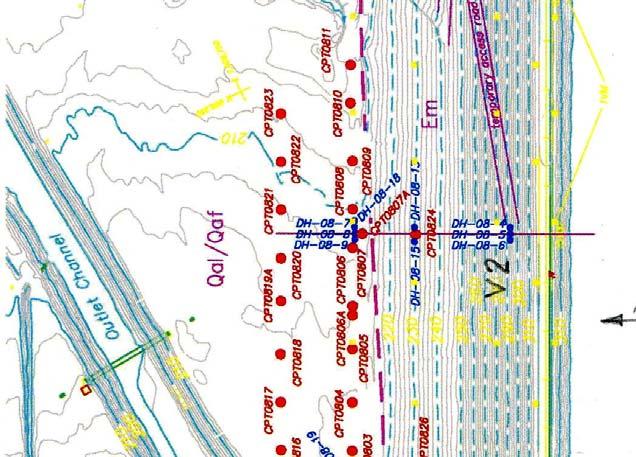

10 Figure 4. Subsurface Exploration Program Paper No. 4.20a 9
11 Figure 5. CPT Data Paper No. 4.20a 10


12 Figure 6. Liquefaction Potential Assessment by SPT Method Paper No. 4.20a 11

13 Figure 7 Torque Head and Test Recorded Sample Figure 8 Plasticity Chart Figure 9. Shear Modulus Reduction, Figure 10. Damping Ratio Reduction Paper No. 4.20a 12

14 Figure 11 Model for the Dynamic Response of the Embankment Figure 12. Vertical Peak Accelerations Figure 13. Horizontal Peak Accelerations Figure 14 Deformation Time History Paper No. 4.20a 13
Evaluation of Geotechnical Hazards
 Evaluation of Geotechnical Hazards by Geoffrey R. Martin Appendix B: Evaluation of Geotechnical Hazards Describes Evaluation Procedures Soil Liquefaction Soil Settlement Surface Fault Rupture Flooding
LIQUEFACTION OF EARTH EMBANKMENT DAMS TWO CASE HISTORIES: (1) LIQUEFACTION OF THE EMBANKMENT SOILS, AND (2) LIQUEFACTION OF THE FOUNDATIONS SOILS
 LIQUEFACTION OF THE EMBANKMENT SOILS, AND (2) LIQUEFACTION OF THE FOUNDATIONS SOILS") LIQUEFACTION OF EARTH EMBANKMENT DAMS TWO CASE HISTORIES: (1) LIQUEFACTION OF THE EMBANKMENT SOILS, AND (2) LIQUEFACTION OF THE FOUNDATIONS SOILS Antonio Fernandez, Ph.D. 1 ABSTRACT Paul C. Rizzo Associates,
LIQUEFACTION OF EARTH EMBANKMENT DAMS TWO CASE HISTORIES: (1) LIQUEFACTION OF THE EMBANKMENT SOILS, AND (2) LIQUEFACTION OF THE FOUNDATIONS SOILS Antonio Fernandez, Ph.D. 1 ABSTRACT Paul C. Rizzo Associates,
SOME OBSERVATIONS RELATED TO LIQUEFACTION SUSCEPTIBILITY OF SILTY SOILS
 SOME OBSERVATIONS RELATED TO LIQUEFACTION SUSCEPTIBILITY OF SILTY SOILS Upul ATUKORALA 1, Dharma WIJEWICKREME 2 And Norman MCCAMMON 3 SUMMARY The liquefaction susceptibility of silty soils has not received
Liquefaction assessments of tailings facilities in low-seismic areas
 Page 1 Liquefaction assessments of tailings facilities in low-seismic areas Holly Rourke SRK Consulting, Perth, WA, Australia Caroline Holmes SRK Consulting, Perth, WA, Australia This paper was first presented
Dynamic Analyses of an Earthfill Dam on Over-Consolidated Silt with Cyclic Strain Softening
 Keynote Lecture: Dynamic Analyses of an Earthfill Dam on Over-Consolidated Silt with Cyclic Strain Softening W.D. Liam Finn University of British Columbia, BC, Canada Guoxi Wu BC Hydro, Burnaby, BC, Canada
Evaluation of the Liquefaction Potential by In-situ Tests and Laboratory Experiments In Complex Geological Conditions
 Evaluation of the Liquefaction Potential by In-situ Tests and Laboratory Experiments In Complex Geological Conditions V. Sesov, K. Edip & J. Cvetanovska University Ss. Cyril and Methodius, Institute of
Cyclic Behavior of Sand and Cyclic Triaxial Tests. Hsin-yu Shan Dept. of Civil Engineering National Chiao Tung University
 Cyclic Behavior of Sand and Cyclic Triaxial Tests Hsin-yu Shan Dept. of Civil Engineering National Chiao Tung University Causes of Pore Pressure Buildup due to Cyclic Stress Application Stress are due
Seismic Evaluation of Tailing Storage Facility
 Australian Earthquake Engineering Society 2010 Conference, Perth, Western Australia Seismic Evaluation of Tailing Storage Facility Jonathan Z. Liang 1, David Elias 2 1 Senior Geotechnical Engineer, GHD
Numerical analysis of effect of mitigation measures on seismic performance of a liquefiable tailings dam foundation
 Numerical analysis of effect of mitigation measures on seismic performance of a liquefiable tailings dam foundation Yong-Beom Lee, Jorge Castillo Ausenco, USA Aurelian C. Trandafir Fugro GeoConsulting
Liquefaction Assessment using Site-Specific CSR
 Liquefaction Assessment using Site-Specific CSR 1. Arup, Sydney 2. Arup Fellow, Adelaide M. M. L.SO 1, T. I. MOTE 1, & J. W. PAPPIN 2 E-Mail: minly.so@arup.com ABSTRACT: Liquefaction evaluation is often
Evaluation of soil liquefaction using the CPT Part 1
 Evaluation of soil liquefaction using the CPT Part 1 Dr. Peter K. Robertson Webinar #7 2013 CPT Guide 5 th Edition Download FREE copy from: Robertson & Cabal (Robertson) 5 th Edition 2012 www.greggdrilling.com
Liquefaction and Foundations
 Liquefaction and Foundations Amit Prashant Indian Institute of Technology Gandhinagar Short Course on Seismic Design of Reinforced Concrete Buildings 26 30 November, 2012 What is Liquefaction? Liquefaction
Dynamic Analysis Contents - 1
 Dynamic Analysis Contents - 1 TABLE OF CONTENTS 1 DYNAMIC ANALYSIS 1.1 Overview... 1-1 1.2 Relation to Equivalent-Linear Methods... 1-2 1.2.1 Characteristics of the Equivalent-Linear Method... 1-2 1.2.2
Address for Correspondence
 Research Paper DYNAMIC ANALYSIS OF KASWATI EARTH DAM 1 Patel Samir K., 2 Prof. C.S.Sanghavi Address for Correspondence 1 Applied Mechanics Department, 2 Professor, L. D. College of Engineering, Gujarat
Seismic Stability of Tailings Dams, an Overview
 Seismic Stability of Tailings Dams, an Overview BY Gonzalo Castro, Ph.D., P.E. Principal International Workshop on Seismic Stability of Tailings Dams Case Western Reserve University, November 2003 Small
Seismic Design of a Hydraulic Fill Dam by Nonlinear Time History Method
 Seismic Design of a Hydraulic Fill Dam by Nonlinear Time History Method E. Yıldız & A.F. Gürdil Temelsu International Engineering Services Inc., Ankara, Turkey SUMMARY: Time history analyses conducted
Boreholes. Implementation. Boring. Boreholes may be excavated by one of these methods: 1. Auger Boring 2. Wash Boring 3.
 Implementation Boreholes 1. Auger Boring 2. Wash Boring 3. Rotary Drilling Boring Boreholes may be excavated by one of these methods: 4. Percussion Drilling The right choice of method depends on: Ground
Date: April 2, 2014 Project No.: Prepared For: Mr. Adam Kates CLASSIC COMMUNITIES 1068 E. Meadow Circle Palo Alto, California 94303
 City of Newark - 36120 Ruschin Drive Project Draft Initial Study/Mitigated Negative Declaration Appendix C: Geologic Information FirstCarbon Solutions H:\Client (PN-JN)\4554\45540001\ISMND\45540001 36120
Investigation of Liquefaction Behaviour for Cohesive Soils
 Proceedings of the 3 rd World Congress on Civil, Structural, and Environmental Engineering (CSEE 18) Budapest, Hungary April 8-10, 2018 Paper No. ICGRE 134 DOI: 10.11159/icgre18.134 Investigation of Liquefaction
An Overview of Geotechnical Earthquake Engineering
 An Overview of Geotechnical Earthquake Engineering Sudhir K Jain Slide 1 Outline Introduction to Seismic Design Principle Dynamic Soil Properties Site Effects Soil Structure Interaction Issues for Foundation
CPT Applications - Liquefaction 2
 CPT Applications - Liquefaction 2 Peter K. Robertson CPT in Geotechnical Practice Santiago, Chile July, 2014 Definitions of Liquefaction Cyclic (seismic) Liquefaction Zero effective stress (during cyclic
Geotechnical Aspects of the Seismic Update to the ODOT Bridge Design Manual. Stuart Edwards, P.E Geotechnical Consultant Workshop
 Geotechnical Aspects of the Seismic Update to the ODOT Bridge Design Manual Stuart Edwards, P.E. 2017 Geotechnical Consultant Workshop Changes Role of Geotechnical Engineer Background Methodology Worked
Safety analyses of Srinagarind dam induced by earthquakes using dynamic response analysis method.
 Safety analyses of Srinagarind dam induced by earthquakes using dynamic response analysis method. S. Soralump Assistance Professor, Faculty of Engineering, Kasetsart University, Thailand. K. Tansupo Ph.D.
Soil Behaviour in Earthquake Geotechnics
 Soil Behaviour in Earthquake Geotechnics KENJI ISHIHARA Department of Civil Engineering Science University of Tokyo This publication was supported by a generous donation from the Daido Life Foundation
Evaluation of soil liquefaction using the CPT Part 2
 Evaluation of soil liquefaction using the CPT Part 2 P.K. Robertson 2013 Definitions of Liquefaction Cyclic (seismic) Liquefaction Zero effective stress (during cyclic loading) Flow (static) Liquefaction
Micro Seismic Hazard Analysis
 Micro Seismic Hazard Analysis Mark van der Meijde INTERNATIONAL INSTITUTE FOR GEO-INFORMATION SCIENCE AND EARTH OBSERVATION Overview Site effects Soft ground effect Topographic effect Liquefaction Methods
EARTHQUAKE-INDUCED SETTLEMENTS IN SATURATED SANDY SOILS
 VOL., NO., AUGUST 7 ISSN 119- -7 Asian Research Publishing Network (ARPN). All rights reserved. EARTHQUAKE-INDUCED SETTLEMENTS IN SATURATED SANDY SOILS C. Y. Lee Department of Civil Engineering, College
Evaluation of liquefaction resistance of non-plastic silt from mini-cone calibration chamber tests
 Evaluation of liquefaction resistance of non-plastic silt from mini-cone calibration chamber tests C.D.P. Baxter, M.S. Ravi Sharma, N.V. Seher, & M. Jander University of Rhode Island, Narragansett, USA
Session 2: Triggering of Liquefaction
 Session 2: Triggering of Liquefaction Plenary Speaker: Geoff Martin Professor Emeritus University of Southern California What are the primary deficiencies in the simplified method for evaluation of liquefaction
APPENDIX J. Dynamic Response Analysis
 APPENDIX J Dynamic Response Analysis August 25, 216 Appendix J Dynamic Response Analysis TABLE OF CONTENTS J1 INTRODUCTION... 1 J2 EARTHQUAKE TIME HISTORIES... 1 J3 MODEL AND INPUT DATA FOR SITE RESPONSE
Geotechnical Earthquake Engineering
 Geotechnical Earthquake Engineering by Dr. Deepankar Choudhury Professor Department of Civil Engineering IIT Bombay, Powai, Mumbai 400 076, India. Email: dc@civil.iitb.ac.in URL: http://www.civil.iitb.ac.in/~dc/
Liquefaction Potential Variations Influenced by Building Constructions
 Earth Science Research; Vol. 1, No. 2; 2012 ISSN 1927-0542 E-ISSN 1927-0550 Published by Canadian Center of Science and Education Liquefaction Potential Variations Influenced by Building Constructions
Investigation of Liquefaction Failure in Earthen Dams during Bhuj Earthquake
 Investigation of Liquefaction Failure in Earthen Dams during Bhuj Earthquake Raghvendra Singh QIP Scholar, Department of Civil Engineering, Indian Institute of Technology, Kharagpur 721302, WB. Email:
Evaluation of Pore Water Pressure Characteristics in Embankment Model.
 Evaluation of Pore Water Pressure Characteristics in Embankment Model. Abdoullah Namdar and Mehdi Khodashenas Pelkoo Mysore University, Mysore, India. 76. Amirkabir University, Department of Mining Engineering,
(THIS IS ONLY A SAMPLE REPORT OR APPENDIX OFFERED TO THE USERS OF THE COMPUTER PROGRAM
 C A U T I O N!! (THIS IS ONLY A SAMPLE REPORT OR APPENDIX OFFERED TO THE USERS OF THE COMPUTER PROGRAM EQLique&Settle2. THE AUTHOR IS HEREBY RELEASED OF ANY LIABILITY FOR ANY INCORRECT USE OF THIS SAMPLE
The Seismic Performance of Tousheh Dam During the Chi-Chi Earthquake
 ( C023) Proceedings of 9 th Conference on Current Researches in Geotechnical Engineering, Shihman Reservoir, Tai-Yuan, Taiwan, R.O.C. August 30-3 and September, 200 92 () (the semi-analysis-testing method)(2)
Finite Deformation Analysis of Dynamic Behavior of Embankment on Liquefiable Sand Deposit Considering Pore Water Flow and Migration
 6 th International Conference on Earthquake Geotechnical Engineering 1-4 November 215 Christchurch, New Zealand Finite Deformation Analysis of Dynamic Behavior of Embankment on Liquefiable Sand Deposit
GEOTECHNICAL SITE CHARACTERIZATION
 GEOTECHNICAL SITE CHARACTERIZATION Neil Anderson, Ph.D. Professor of Geology and Geophysics Richard W. Stephenson, P.E., Ph.D. Professor of Civil, Architectural and Environmental Engineering University
Effective stress analysis of pile foundations in liquefiable soil
 Effective stress analysis of pile foundations in liquefiable soil H. J. Bowen, M. Cubrinovski University of Canterbury, Christchurch, New Zealand. M. E. Jacka Tonkin and Taylor Ltd., Christchurch, New
Evaluating the Seismic Coefficient for Slope Stability Analyses
 Evaluating the Seismic Coefficient for Slope Stability Analyses by Edward Kavazanjian, Jr., Ph.D., P.E.,D.GE., NAE Ira A. Fulton Professor of Geotechnical Engineering School of Sustainable Engineering
NEW METHOD FOR LIQUEFACTION ASSESSMENT BASED ON SOIL GRADATION AND RELATIVE DENSITY
 NEW METHOD FOR LIQUEFACTION ASSESSMENT BASED ON SOIL GRADATION AND RELATIVE DENSITY Bambang Istijono 1, Abdul Hakam 2 1,2 Civil Dept. of Engineering Faculty, University of Andalas, Padang, Indonesia ABSTRACT
Cyclic Triaxial Testing of Water-Pluviated Fly Ash Specimens
 2013 World of Coal Ash (WOCA) Conference - April 22-25, 2013 in Lexington, KY http://www.flyash.info/ Cyclic Triaxial Testing of Water-Pluviated Fly Ash Specimens Jeffrey S. Dingrando 1, Michael E. Kalinski
LIQUEFACTION ASSESSMENT OF INDUS SANDS USING SHEAR WAVE VELOCITY
 Pakistan Engineering Congress, 69th Annual Session Proceedings 219 LIQUEFACTION ASSESSMENT OF INDUS SANDS USING SHEAR WAVE VELOCITY Sohail Kibria 1, M. Javed 2, Muhammad Ali 3 ABSTRACT A host of procedures
DRAFT ONONDAGA LAKE CAPPING AND DREDGE AREA AND DEPTH INITIAL DESIGN SUBMITTAL H.4 SEISMIC SLOPE STABILITY ANALYSES
 DRAFT ONONDAGA LAKE CAPPING AND DREDGE AREA AND DEPTH INITIAL DESIGN SUBMITTAL H.4 SEISMIC SLOPE STABILITY ANALYSES Parsons P:\Honeywell -SYR\444576 2008 Capping\09 Reports\9.3 December 2009_Capping and
DEVELOPMENT OF A METHODOLOGY FOR ESTIMATING SIMPLIFIED SEISMIC SLOPE DEFORMATION OF LEVEES WITH SEEPAGE CONTROL MEASURES
 Paper No. DOALI DEVELOPMENT OF A METHODOLOGY FOR ESTIMATING SIMPLIFIED SEISMIC SLOPE DEFORMATION OF LEVEES WITH SEEPAGE CONTROL MEASURES John Liao 1, Ph.D., P.E., Zia Zafir, Ph.D., P.E., G.E., Scott Anderson,
APPENDIX F CORRELATION EQUATIONS. F 1 In-Situ Tests
 APPENDIX F 1 APPENDIX F CORRELATION EQUATIONS F 1 In-Situ Tests 1. SPT (1) Sand (Hatanaka and Uchida, 1996), = effective vertical stress = effective friction angle = atmosphere pressure (Shmertmann, 1975)
Gravity dam and earthquake
 Gravity dam and earthquake Tardieu s Dynamic simplified method Patrick LIGNIER, Tractebel Engineering Coyne et Bellier Château des Comtes de Challes 9 octobre 2014 CONTENTS 2 Vulnerability of gravity dam
Guidelines for Site-Specific Seismic Hazard Reports for Essential and Hazardous Facilities and Major and Special-Occupancy Structures in Oregon
 Guidelines for Site-Specific Seismic Hazard Reports for Essential and Hazardous Facilities and Major and Special-Occupancy Structures in Oregon By the Oregon Board of Geologist Examiners and the Oregon
B-1 BORE LOCATION PLAN. EXHIBIT Drawn By: 115G BROOKS VETERINARY CLINIC CITY BASE LANDING AND GOLIAD ROAD SAN ANTONIO, TEXAS.
 N B-1 SYMBOLS: Exploratory Boring Location Project Mngr: BORE LOCATION PLAN Project No. GK EXHIBIT Drawn By: 115G1063.02 GK Scale: Checked By: 1045 Central Parkway North, Suite 103 San Antonio, Texas 78232
GEOTECHNICAL SEISMIC HAZARDS
 Chapter 13 GEOTECHNICAL SEISMIC HAZARDS FINAL SCDOT GEOTECHNICAL DESIGN MANUAL June 2010 Table of Contents Section Page 13.1 Introduction... 13-1 13.2 Geotechnical Seismic Hazard Failure Modes... 13-2
Harmonized European standards for construction in Egypt
 Harmonized European standards for construction in Egypt EN 1998 - Design of structures for earthquake resistance Jean-Armand Calgaro Chairman of CEN/TC250 Organised with the support of the Egyptian Organization
Chapter (5) Allowable Bearing Capacity and Settlement
 Allowable Bearing Capacity and Settlement") Chapter (5) Allowable Bearing Capacity and Settlement Introduction As we discussed previously in Chapter 3, foundations should be designed for both shear failure and allowable settlement. So the allowable
Chapter (5) Allowable Bearing Capacity and Settlement Introduction As we discussed previously in Chapter 3, foundations should be designed for both shear failure and allowable settlement. So the allowable
2-D Liquefaction Evaluation with Q4Mesh
 2005 Tri-Service Infrastructure Systems Conference and Exhibition 2-D Liquefaction Evaluation with Q4Mesh -David C. Serafini, M.S., P.E. US Army Corps, Sacramento, CA 3 August 2005 2005 Tri-Service ISC
DYNAMIC RESPONSE APPROACH AND METHODOLOGY
 DYNAMIC RESPONSE APPROACH AND METHODOLOGY Traditional seismic stability procedures vs coupled effective-stress approach. Traditional seismic stability procedures: Empirical and laboratory corrections and
The Effect of Earthquake Record Scaling Technique on Embankment Dam Response
 Missouri University of Science and Technology Scholars' Mine International Conferences on Recent Advances in Geotechnical Earthquake Engineering and Soil Dynamics 20 - Fifth International Conference on
SLOPE STABILITY EVALUATION AND ACCEPTANCE STANDARDS
 INFORMATION BULLETIN / PUBLIC - BUILDING CODE REFERENCE NO.: LABC 7006.3, 7014.1 Effective: 01-01-2017 DOCUMENT NO.: P/BC 2017-049 Revised: 12-21-2016 Previously Issued As: P/BC 2014-049 SLOPE STABILITY
Table of Contents Chapter 1 Introduction to Geotechnical Engineering 1.1 Geotechnical Engineering 1.2 The Unique Nature of Soil and Rock Materials
 Table of Contents Chapter 1 Introduction to Geotechnical Engineering 1.1 Geotechnical Engineering 1.2 The Unique Nature of Soil and Rock Materials 1.3 Scope of This Book 1.4 Historical Development of Geotechnical
Liquefaction: Additional issues. This presentation consists of two parts: Section 1
 Liquefaction: Additional issues Ahmed Elgamal This presentation consists of two parts: Section 1 Liquefaction of fine grained soils and cyclic softening in silts and clays Section 2 Empirical relationship
Numerical model comparison on deformation behavior of a TSF embankment subjected to earthquake loading
 Numerical model comparison on deformation behavior of a TSF embankment subjected to earthquake loading Jorge Castillo, Yong-Beom Lee Ausenco, USA Aurelian C. Trandafir Fugro GeoConsulting Inc., USA ABSTRACT
On seismic landslide hazard assessment: Reply. Citation Geotechnique, 2008, v. 58 n. 10, p
 Title On seismic landslide hazard assessment: Reply Author(s) Yang, J; Sparks, A.D.W. Citation Geotechnique, 28, v. 58 n. 1, p. 831-834 Issued Date 28 URL http://hdl.handle.net/1722/58519 Rights Geotechnique.
A comparison between two field methods of evaluation of liquefaction potential in the Bandar Abbas City
 American Journal of Civil Engineering 2015; 3(2-2): 1-5 Published online January 16, 2015 (http://www.sciencepublishinggroup.com/j/ajce) doi: 10.11648/j.ajce.s.2015030202.11 ISSN: 2330-8729 (Print); ISSN:
Soil Properties - II
 Soil Properties - II Amit Prashant Indian Institute of Technology andhinagar Short Course on eotechnical Aspects of Earthquake Engineering 04 08 March, 2013 Seismic Waves Earthquake Rock Near the ground
Evaluation of Liquefaction Potential of Impounded Fly Ash
 2007 World of Coal Ash (WOCA), May 7-10, 2007, Northern Kentucky, USA http://www.flyash.info Evaluation of Liquefaction Potential of Impounded Fly Ash Behrad Zand 1*, Wei Tu 2, Pedro J. Amaya 3, William
CPT Data Interpretation Theory Manual
 CPT Data Interpretation Theory Manual 2016 Rocscience Inc. Table of Contents 1 Introduction... 3 2 Soil Parameter Interpretation... 5 3 Soil Profiling... 11 3.1 Non-Normalized SBT Charts... 11 3.2 Normalized
Evaluating Soil Liquefaction and Post-earthquake deformations using the CPT
 Evaluating Soil Liquefaction and Post-earthquake deformations using the CPT P.K. Robertson University of Alberta, Dept. of Civil and Environmental Engineering, Edmonton, Canada Keywords: Soil liquefaction,
Dynamic properties and liquefaction potential of soils
 Dynamic properties and liquefaction potential of soils T. G. Sitharam*, L. GovindaRaju and A. Sridharan Department of Civil Engineering, Indian Institute of Science, Bangalore 560 012, India Design of
University, 470 Hitchcock Hall, 2070 Neil Ave., Columbus, OH 43210, US, Tel: (614) 292-
 292-") 2013 World of Coal Ash (WOCA) Conference - April 22-25, 2013 in Lexington, KY http://www.flyash.info/ Liquefaction Potential of Impounded Class F Fly Ash Nathan A. Yencho 1, Brian C. Dudley 1, Pedro J.
2013 World of Coal Ash (WOCA) Conference - April 22-25, 2013 in Lexington, KY http://www.flyash.info/ Liquefaction Potential of Impounded Class F Fly Ash Nathan A. Yencho 1, Brian C. Dudley 1, Pedro J.
Use of CPT in Geotechnical Earthquake Engineering
 Use of CPT in Geotechnical Earthquake Engineering Prof. Scott M. Olson, PhD, PE Use of Cone Penetration Test for Foundation Analysis and Design 2006 Annual Meeting Transportation Research Board Geotechnical
1D Analysis - Simplified Methods
 1D Equivalent Linear Method Page 1 1D Analysis - Simplified Methods Monday, February 13, 2017 2:32 PM Reading Assignment Lecture Notes Pp. 255-275 Kramer (EQL method) p. 562 Kramer (Trigonometric Notation
Guidelines on Foundation Loading and Deformation Due to Liquefaction Induced Lateral Spreading
 Guidelines on Foundation Loading and Deformation Due to Liquefaction Induced Lateral Spreading February, 2011 1 INTRODUCTION Past earthquakes offer many examples of bridges that either collapsed or incurred
1.1 Calculation methods of the liquefaction hazard.
 1 Theoretical basis 1.1 Calculation methods of the liquefaction hazard. 1.1.1 Empirical methods. Empirical methods are generally used to get a rough estimate of the liquefaction hazard in saturated sandy
LIQUEFACTION OF SILT-CLAY MIXTURES
 LIQUEFACTION OF SILT-CLAY MIXTURES Tianqiang GUO 1 And Shamsher PRAKASH 2 SUMMARY No guidelines are available for evaluating the liquefaction potential of silt-clay mixtures during an earthquake, based
Liquefaction-Induced Ground Deformations Evaluation Based on Cone Penetration Tests (CPT)
") World Journal of Engineering and Technology, 2014, 2, 249-259 Published Online November 2014 in SciRes. http://www.scirp.org/journal/wjet http://dx.doi.org/10.4236/wjet.2014.24026 Liquefaction-Induced
World Journal of Engineering and Technology, 2014, 2, 249-259 Published Online November 2014 in SciRes. http://www.scirp.org/journal/wjet http://dx.doi.org/10.4236/wjet.2014.24026 Liquefaction-Induced
STEVENS CREEK DAM SEISMIC STABILITY EVALUATIONS OF CHESBRO, LENIHAN, STEVENS CREEK, AND UVAS DAMS (SSE2) PHASE A: STEVENS CREEK AND LENIHAN DAMS
 PHASE A: STEVENS CREEK AND LENIHAN DAMS") SEISMIC STABILITY EVALUATIONS OF CHESBRO, LENIHAN, STEVENS CREEK, AND UVAS DAMS (SSE2) PHASE A: STEVENS CREEK AND LENIHAN DAMS STEVENS CREEK DAM COMPILATION REPORT (REPORT No. SSE2A-SC) Prepared for SANTA
SEISMIC STABILITY EVALUATIONS OF CHESBRO, LENIHAN, STEVENS CREEK, AND UVAS DAMS (SSE2) PHASE A: STEVENS CREEK AND LENIHAN DAMS STEVENS CREEK DAM COMPILATION REPORT (REPORT No. SSE2A-SC) Prepared for SANTA
ASSESSMENT OF SEISMIC RISK FOR THE DESIGN OF OFFSHORE STRUCTURES IN LIQUEFIABLE SOIL
 th International Conference on Earthquake Geotechnical Engineering June 5-, 7 Paper No. 3 ASSESSMENT OF SEISMIC RISK FOR THE DESIGN OF OFFSHORE STRUCTURES IN LIQUEFIABLE SOIL Barnali GHOSH 1, Navin PEIRIS,
Behavior of Soft Riva Clay under High Cyclic Stresses
 Behavior of Soft Riva Clay under High Cyclic Stresses Mustafa Kalafat Research Assistant, Boğaziçi University, Istanbul, Turkey; mkalafat@boun.edu.tr Canan Emrem, Ph.D., Senior Engineer, ZETAS Zemin Teknolojisi
Module 6 LIQUEFACTION (Lectures 27 to 32)
") Module 6 LIQUEFACTION (Lectures 27 to 32) Lecture 31 Topics 6.6 EFFECTS OF LIQUEFACTION 6.6.1 Alteration of Ground Motion 6.6.2 Development of Sand Boils 6.6.3 Settlement 6.6.4 Settlement of Dry Sands
Module 6 LIQUEFACTION (Lectures 27 to 32) Lecture 31 Topics 6.6 EFFECTS OF LIQUEFACTION 6.6.1 Alteration of Ground Motion 6.6.2 Development of Sand Boils 6.6.3 Settlement 6.6.4 Settlement of Dry Sands
Some Recent Advances in (understanding) the Cyclic Behavior of Soils
 the Cyclic Behavior of Soils") 39 th SPRING SEMINAR and 19 th LA GEO EXPO American Society of Civil Engineers Geo-Institute, Los Angeles Section Wednesday April 13, 216 Queen Mary, Long Beach, CA 982 Invited lecture: Some Recent Advances
39 th SPRING SEMINAR and 19 th LA GEO EXPO American Society of Civil Engineers Geo-Institute, Los Angeles Section Wednesday April 13, 216 Queen Mary, Long Beach, CA 982 Invited lecture: Some Recent Advances
EMPIRICAL EVIDENCE FROM THE NORTHRIDGE EARTHQUAKE FOR SITE- SPECIFIC AMPLIFICATION FACTORS USED IN US BUILDING CODES
 EMPIRICAL EVIDENCE FROM THE NORTHRIDGE EARTHQUAKE FOR SITE- SPECIFIC AMPLIFICATION FACTORS USED IN US BUILDING CODES Roger D BORCHERDT And Thomas E FUMAL SUMMARY Site-specific amplification factors, F
PROPOSED CHANGE TO THE 2012 BUILDING CODE O. REG. 332/12 AS AMENDED
 Ministry of Municipal Affairs PROPOSED CHANGE TO THE 2012 BUILDING CODE O. REG. 332/12 AS AMENDED CHANGE NUMBER: SOURCE: B-04-01-15 Ontario-NBC CODE REFERENCE: Division B / 4.1.8.2. Division B / 4.1.8.4.
IGC. 50 th INDIAN GEOTECHNICAL CONFERENCE ESTIMATION OF FINES CONTENT FROM CPT PARAMETERS FOR CALCAREOUS SOILS OF WESTERN INDIAN OFFSHORE
 5 th 5 th INDIAN GEOTECHNICAL CONFERENCE 17 th 19 th DECEMBER 215, Pune, Maharashtra, India ESTIMATION OF FINES CONTENT FROM CPT PARAMETERS FOR CALCAREOUS SOILS OF WESTERN INDIAN OFFSHORE Alankar Srivastava
Comparison of different methods for evaluating the liquefaction potential of sandy soils in Bandar Abbas
 Comparison of different methods for evaluating the liquefaction potential of sandy soils in Bandar Abbas M. Mosaffa¹ & M. Rafiee² 1.Geotechnical M.S. student Hormozgan University, Bandar Abbas, Iran(Email:Amestris@gmail.com).Geotechnical
Seismic Stability and Rehabilitation Analysis of a Hydraulic Fill Dam
 Missouri University of Science and Technology Scholars' Mine International Conferences on Recent Advances in Geotechnical Earthquake Engineering and Soil Dynamics 2001 - Fourth International Conference
SITE INVESTIGATION 1
 SITE INVESTIGATION 1 Definition The process of determining the layers of natural soil deposits that will underlie a proposed structure and their physical properties is generally referred to as site investigation.
Back Analysis of the Lower San Fernando Dam Slide Using a Multi-block Model
 Proceedings Geohazards Engineering Conferences International Year 2006 Back Analysis of the Lower San Fernando Dam Slide Using a Multi-block Model C. A. Stamatopoulos P. Petridis Stamatopoulos and Associates
Geo-Seismic Environmental Aspects Affecting Tailings Dams Failures
 American Journal of Environmental Sciences 4 (3): 212-222, 28 ISSN 1553-345X 28 Science Publications Geo-Seismic Environmental Aspects Affecting Tailings Dams Failures Juan M. Mayoral and Miguel P. Romo
Cone Penetration Testing in Geotechnical Practice
 Cone Penetration Testing in Geotechnical Practice Table Of Contents: LIST OF CONTENTS v (4) PREFACE ix (2) ACKNOWLEDGEMENTS xi (1) SYMBOL LIST xii (4) CONVERSION FACTORS xvi (6) GLOSSARY xxii 1. INTRODUCTION
H.1 SUMMARY OF SUBSURFACE STRATIGRAPHY AND MATERIAL PROPERTIES (DATA PACKAGE)
") DRAFT ONONDAGA LAKE CAPPING AND DREDGE AREA AND DEPTH INITIAL DESIGN SUBMITTAL H.1 SUMMARY OF SUBSURFACE STRATIGRAPHY AND MATERIAL PROPERTIES (DATA PACKAGE) Parsons P:\Honeywell -SYR\444576 2008 Capping\09
DRAFT ONONDAGA LAKE CAPPING AND DREDGE AREA AND DEPTH INITIAL DESIGN SUBMITTAL H.1 SUMMARY OF SUBSURFACE STRATIGRAPHY AND MATERIAL PROPERTIES (DATA PACKAGE) Parsons P:\Honeywell -SYR\444576 2008 Capping\09
Cyclic Softening of Low-plasticity Clay and its Effect on Seismic Foundation Performance
 4th International Conference on Earthquake Engineering Taipei, Taiwan October 12-13, 6 Paper No. 287 Cyclic Softening of Low-plasticity Clay and its Effect on Seismic Foundation Performance Daniel B. Chu
Case History of Observed Liquefaction-Induced Settlement Versus Predicted Settlement
 Case History of Observed Liquefaction-Induced Settlement Versus Predicted Settlement M. Lew and L. Tran AMEC Environment & Infrastructure, Inc., Los Angeles, CA USA SUMMARY: A comparison of the predicted
Site Response Using Effective Stress Analysis
 Site Response Using Effective Stress Analysis Faiz Makdisi, Zhi-Liang Wang, C.Y. Chang and J. Egan Geomatrix Consultants, Inc. Oakland, California 1 TRB 85 th Annual Meeting, January 22-26, 26, 2006, Washington,
Cyclic Behavior of Soils
 Cyclic Behavior of Soils Antonios Vytiniotis Cyclic Shearing of Sands Dry Sand 1 Triaxial Undrained Monotonic Shearing CIUC tests Ishihara Critical State Toyoura Sand Ishihara 2 Critical State Ishihara
Mitigation of Liquefaction Potential Using Rammed Aggregate Piers
 ASCE 2011 557 Mitigation of Liquefaction Potential Using Rammed Aggregate Piers R.W. Rudolph, M. ASCE, G.E. 1, B. Serna, M. ASCE, P.E. 2, and T. Farrell, M. ASCE, G.E. 3 1 Principal Consultant, ENGEO,
Liquefaction Potential Post-Earthquake in Yogyakarta
 The 17 th Southeast Asian Geotechnical Conference Taipei, Taiwan, May 10~13, 2010 Liquefaction Potential Post-Earthquake in Yogyakarta AGUS SETYO MUNTOHAR 1 and S.P.R. WARDANI 2 1 Department of Civil Engineering,
QUAKE/W ProShake Comparison
 1 Introduction QUAKE/W Comparison is a commercially available software product for doing one-dimensional ground response analyses. It was developed and is being maintained under the guidance of Professor
SEEPAGE ANALYSIS AND SEISMIC BEHAVIOUR OF EARTH FILL DAM USING GEO-STUDIO
 SEEPAGE ANALYSIS AND SEISMIC BEHAVIOUR OF EARTH FILL DAM USING GEO-STUDIO Mr. PAVAN N¹, Mrs. BARNALI GHOSH², Dr.S.K.PRASAD³ 1 P.G STUDENT, East Point College Of Engineering & Technology 2 ASSOCIATE PROFESSOR,
CYCLIC SOFTENING OF LOW-PLASTICITY CLAY AND ITS EFFECT ON SEISMIC FOUNDATION PERFORMANCE
 4 th International Conference on Earthquake Geotechnical Engineering June 25-28, 27 Paper No. 149 CYCLIC SOFTENING OF LOW-PLASTICITY CLAY AND ITS EFFECT ON SEISMIC FOUNDATION PERFORMANCE Daniel B. Chu
8.1. What is meant by the shear strength of soils? Solution 8.1 Shear strength of a soil is its internal resistance to shearing stresses.
 8.1. What is meant by the shear strength of soils? Solution 8.1 Shear strength of a soil is its internal resistance to shearing stresses. 8.2. Some soils show a peak shear strength. Why and what type(s)
Comparison of CPT Based Liquefaction Potential and Shear Wave Velocity Maps by Using 3-Dimensional GIS
 Comparison of CPT Based Liquefaction Potential and Shear Wave Velocity Maps by Using 3-Dimensional GIS Muammer Tün, Uğur Avdan, Metin Altan, Can Ayday Anadolu University, Satellite and Space Sciences Research
Evaluation of Earthquake Liquefaction Hazard of Kutch Region
 Journal of Geotechnical and Transportation Engineering Volume 3 Issue 2 Evaluation of Earthquake Liquefaction Hazard of Kutch Region Hussain and Sachan Received 6/7/2017 Accepted 10/4/2017 Published 12/1/2017