1.1 Calculation methods of the liquefaction hazard.
|
|
|
- Elfreda Osborne
- 6 years ago
- Views:
Transcription
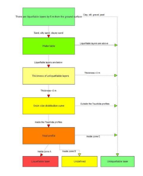
1 1 Theoretical basis 1.1 Calculation methods of the liquefaction hazard Empirical methods. Empirical methods are generally used to get a rough estimate of the liquefaction hazard in saturated sandy layers, taking into account only the geological-geotechnical characteristics of the investigated site. They're simplified methods to use in case of surveys of seismic microzonation Sherif & Ishibashi (1978). The Sherif & Ishibashi method is based on the premise that the soil layers have the following requirements: - they are made up by sand or silty sand; - they're below the level of the water table; - the non-liquefiable layers, on the top, have a total thickness lower than 3 meters. according to the following flow diagram:
2
3 If these requirements are present, it goes on in the procedure, taking into account the granulometry and the relative density of the soil layer. The method requires that a granulometric analysis be executed, taking a sample of the soil layer. The resulting curves has to be compared with the two critical profiles (Tsuchida, 1970), the first one related to a uniform granulometry, the second one to a non-uniform granulometry. Checked that the granulometric curve of the soil layer falls within the critical limits, it's possible to proceed, taking into account the relative density of the soil layer through SPT or DP tests. If the number of blows, even if partially, falls inside the A zone, the layer is liquefiable. If it falls inside the C zone is unliquefiable. The hazard is undefined in case of profile within the B zone.
4 Nspt Zone C: not liquefiable Depth (m) 10 Zone A: liquefiable Zone B: undefined Ishihara (1985). It's an empirical method based on a graphic. The required data are the thickness of the unliquefiable layers (H 1 ), the thickness of the liquefiable layers below (H 2 ) and the peak ground acceleration (PGA). According the Author, saturated sandy layers with N spt <10 are to be considered liquefiable. The Ishihara procedure gives, in a purely qualitative manner, the magnitude of the ground deformations and consequently the damage level in case of liquefaction.
5 Ishihara diagram Methods based on the seismic magnitude. They're empirical formulas which associate the epicentral distance from the investigated site to the critical seismic magnitude, that is the moment magnitude beyond which liquefaction events could become possible in saturated sandy layers. This magnitude must be compared with the moment magnitude of the seismic event used as reference (M). Ambraseys(1991) 8 Mc dist Log10 ( dist )
6 Papadopulos and Lefkopulos(1993) 8 Mc dist Log Galli (2000) Mc Log10 ( dist) ( dist ) where dist is the epicentral distance in km. Thus, if the ratio M/Mc is higher than 1, liquefaction phenomenons become possible Method based on the Arias Intensity. The Arias Intensity (1970) represents an index proportional to the energy released by the seismic event. Practically it's the integral of the square of the seismic acceleration extended to all the duration T of the accelerogram: T Ia 2 a ( t dt 2g ) o The significant duration of the earthquake is defined as the time interval between 5% and 95% of the Arias intensity. The variability of Ia as a function of the depth h can be gotten through the empirical formula of Kayen e Mitchell (1997): Ia( h) Ia 35 rb exp sen 0. 09h 2 M w where M w is the moment magnitude of the earthquake of reference. The Arias Intensity can be correlated to the liquefaction risk through the following scheme: r b
7 where N 1,60cs represents the number of blows SPT normalized in case of clean sand. The N 1,60cs parameter is given, applying a correction to Nspt, chosen between the formulas proposed by several Authors. The clean-sand boundary of the graph can be correlated to the CRR parameter through the following formula: Ihb CRR lim 100 2
8 1.1.2 Simplified methods. Simplified methods allow to quantify the liquefaction risk through a safety factor given by the ratio between the shear resistance of the soil layer (CRR) and the shear stress produced by the earthquake (CSR): CRR F s. CSR A soil layer can be classified as a liquefiable level if the safety factor is lower than 1 (1.25 according the Eurocode 8). The CSR variable depend on the parameters of the earthquake of reference (PGA and moment magnitude). CRR is as function of the geotechnical characteristics of the soil layer, mainly by its relative density, and can be directly given through correlations with penetrometer tests (SPT and CPT) and geophysical surveys, the latter to get a S waves profile Evaluation of shear stress generated by an earthquake (CSR). The CSR parameter is given by the following relation: amax v0 1 T 0.65 rd ; g v0 ' MSF where: a max = peak ground acceleration; g = acceleration of gravity = cm/s 2 ; v0 = vertical total pressure at the depth z from the ground; v0 = vertical effective pressure at the depth z from the ground; r d = variable as a function of the depth from the ground; MSF = corrective coefficient as a function of the seismic magnitude.
9 The variable rd can be calculated through several empirical correlations, known in literature. Seed (1971) rd h media h media (mean depth of the layer) < 10m rd h media h media 10m Liao & Whitman (1986) rd h media h media 9.15m rd h media 9.15<h media 23m rd h media 23<h media 30m rd 0.5 h media >30m Blake (1996) rd hmedia hmedia hmedia hmedia hmedia hmedia hmedia Boulanger & Idriss (2014) rd exp( ) h media sen hmedia M w sen where M w is the moment magnitude.
10 The corrective coefficient MSF can be computed, in case of SPT and CPT, through the expressions dby Boulanger & Idriss (2014): where: In case of empirical methods based on the shear wave velocity, the formula by Idriss (1999) can be used: As an alternative, it may use the method by Idriss (1995): M 7.5 M>7.5.
11 Evaluation of the shear strength of the soil (CRR) By dynamic penetration tests (SPT) Tokimatsu & Yoshimi (1983). According the Tokimatsu & Yoshimi method, CRR is given by the following formula: where: Na 14 CRR Na 0.21 Na 1.7 = N spt N1 v 0.7 v (kg/cmq) = vertical effective pressure; N 1 = 0 when percentage of fines is p c < 5%, 10 p c +4 when p c 5 % By dynamic penetration tests (SPT) Seed et al. (1985). CRR is calculated by the following relation: CRR a cx ex bx dx fx hx 2 gx 3 where: x = N 1,60cs number of blows SPT in case of a 60% energy efficiency, corrected to take into account the fine component (silt and clay). a =0.048; b = ; c = ; d = ; e = ; f = ; g = ; h =
12 N 1, 60cs can be calculated by the following formula: N1,60cs f a fb ( CEC NCbCrCs Nspt) where: = correction factor as a function of the depth of the measurement = C N 1 ( v in kg/cmq); if C N > 1.7 put C N = 1.7; C E C b C r C s f a f b v = correction factor as a function of the energy efficiency= ER/60 with ER% is the efficiency of the used probe; = correction factor as a function of the borehole diameter; these the recommended values: from 65 to 115 mm C b =1.0 from 115 to 150 mm C b =1.05 from 150 to 200 mm C b =1.15 = correction factor as a function of the rod length; these the recommended values: from 3 to 4 m C r =0.75 from 4 to 6 m C r =0.85 from 6 to 10 m C r =0.95 from 10 to 30 m C r =1.0 >30 m C r >1.0 = correction factor as a function of type of sampler; these the recommended values: standard C s =1.0 without liners C s da 1.1 a 1.3 = 0 when the percentage of fines (FC)5%; 190 = exp when 5<FC<35 %; FC =5 when FC35 %; = 1 for FC5%; 1.5 FC = 0.99 for 5<FC<35 %; 1000 =1.2 for FC35 %.
13 By dynamic penetration tests (SPT) Youd et al.(2001) CRR is given by the following relation: 1 CRR 34 N 1,60cs N 1,60cs N 50 1,60cs By dynamic penetration tests (SPT) Boulanger & Idriss(2014) CRR is estimated through the following formula: 3 4 N 1,60cs N1,60cs N1,60cs N1,60cs CRR exp N 1,60cs is given by this relation: N 1,60 cs N1,60 exp 1.63 FC FC where FC is the percentage of fines and N 1,60 is the normalized Nspt value. Its expression is the following: N 1,60 Nspt C N C E C R CS C B The variables C E, C R, C S e C B have the same expressions seen in the case of the Seed & Al.'s method. The parameter C N can be estimated in a iterative way, proceeding according this scheme: 1. A initial value of N 1,60 is calculated, assuming (kpa)= vertical effective pressure; C N 2. C N is then recalculated using the following expression: where N1, N 1,60 is estimated again through the new value of C N; 98.1 ' C N, where 98.1 '
14 4. Steps 2 and 3 are repeated till when the difference between the values of C N calculated in two consecutive cycles is lower than a chosen limit. If C N is higher than 1.7, put C N = By static penetration tests (CPT) Robertson & Wride (1997). Robertson & Wride's method permits to correlate the soil shear resistance to the data of a static penetration test (CPT). The procedure of calculation is based on the two following equations: q c 1n cs CRR (q c1n ) cs <50 and q c 3 1n cs CRR (q c1n ) cs < The variable (q c1n ) cs represents the normalized point resistance, corrected to take into account the percentage of fines. The calculation of (q c1n ) cs is performed through the following steps. The normalized cone resistance and friction ratio are evaluated through the following relations: q Q c e v0 ' v0 F 100 q c f s v0 where: q c (kg/cmq) f s (kg/cmq) v0 (kg/cmq) v0 (kg/cmq) = measured cone resistance; = measured sleeve friction; = vertical total pressure; = vertical effective pressure. The soil behavior type index of the sandy layer is calculated: Ic 2 Log F 1.22 Log Q
15 The correction to take into account the depth of the test is estimated: 1 qc 1 n CQqc dove C Q v0 ' The exponent n is evaluated in the following way: if Ic>2.6 then n=1; if Ic2.6 an initial value of q c1n, is calculated, using n=0.5; then Ic is recalculated through this relation: Ic 2 Log F 1.22 Log q c 1n 47 if the new Ic value is lower than 2.6 again, a value n=0.5 is used, otherwise q c1n is recalculated, using n=0.75; if q c1n >2q c put q c1n =2q c. Finally the correction as a function of fines in the sandy layer is evaluated: ( q ) c1 n cs K cqc1n, where K c is 1, if Ic1.64, otherwise it's given by the following relation: n K c 0.403Ic Ic Ic Ic By static penetration tests (CPT) Boulanger & Idriss(2014) CRR is given by the following expression: The variable qc 1n has to be estimated through an iterative way, proceeding according the following scheme: qc 1. An initial value of qc 1n, is calculated, imposing qc1 n ; 98.1
16 2. The corrective factor C Q is evaluated through the following relation: 98.1 C Q where (kpa)= vertical effective pressure and ' qc 1 1n qc 3. qc 1n is recalculated by the expression qc 1n CQ Steps 2 and 3 are repeated till when the difference between the values of C Q calculated in two consecutive cycles is lower than a chosen limit. If C Q is higher then 1.7, put C Q =1.7. The parameter qc 1ncs is given by qc 1n, inserting a correction to take into account the percentage of fines inside the sandy layer. where: and: By Vs profiles Andrus & Stokoe(1997). The liquefaction resistance of a soil layer can be evaluated through empirical methods as a function of the S wave velocity. The Andrus & Stokoe's method is based on the following expression: V R s V s1c V s1 V s1 where:
17 1 V s1 (m/s) = corrected S wave velocity = V ' s, where V s is the v0 measured velocity and v0 (kg/cmq) is the vertical effective pressure in the midpoint of the layer; V s1c (m/s) = critical value of the S wave velocity in the layer, given by the following scheme: V s1c (m/s)=220 if the percentage of fines(fc)<5%; V s1c (m/s)=210 if FC=20%; V s1c (m/s)=200 if FC>35%; interpolating in case of intermediate values of FC By Vs profile Boulanger & Idriss(2004) The relation is the following: 0.25 V R s V s1c V s1 V s1 where: 1 V s1 (m/s) = corrected S wave velocity in the sandy layer = V ' s, v0 where V s is the measured velocity and v0 (kg/cmq) is the vertical effective pressure in the midpoint of the layer; V s1c (m/s) = critical value of the S wave velocity in the layer, given by the following scheme: V s1c (m/s)=215 if the percentage of fines (FC)<5%; V s1c (m/s)= x(fc-5) if 5<FC<35%; V s1c (m/s)=200 if FC35%; Evaluating CRR in case of external loads and/or slope of the ground surface. The calculation methods of CRR seen in the previous paragraphs are valid in case of absence of external loads (free-field condition) and where the 0.25
18 ground surface is horizontal. If these conditions aren't satisfied, it's possible to evaluate CRR using the following relation: CRR CRR K K 0 where: CRR 0 = CRR calculated in case of free-field condition and horizontal ground surface K = corrective factor for external loads or high values of the effective pressure; K = corrective factor for slope ground surface (shear stress>0 in static condition). The variable K is a reducing coefficient suggested because of the measured decrease of CRR in presence of high values of v0. This effect is substantial in case of v0 values higher than 200 kpa. Without external loads (free field condition) these values of v0, in saturated layers, are reached at depth higher than 15 m. K can be estimated through the following empirical formula ( Boulanger & Idriss, 2004): v0 ' K C 1 ln pa where: 1 C 0,3 by SPT; N C C q c 1N V 100 s 1 / ,3 by CPT; 0,3 by Vs profile. The corrective factor K quantifies the effect of a static shear stress inside the soil before the seismic event. A rough value of K can be gotten by the following chart, as a function of the relative density (D r ). The parameter is given by the ratio between the static shear stress and the vertical effective pressure.
19 The applicability of K is restricted at cases where v0 is lower or equal than about 300 kpa. Beyond this limit the effect of the effective pressure cancels the one due to the static shear stress. In these cases only K has to be applied Calculation of the liquefaction potential index. An estimate of the liquefaction hazard along a specific vertical of calculation is given by the parameter Index of Liquefaction (IL). Such an index is estimable through the following relation: IL n i1 FW ( z) z
20 where: n = calculation steps of SF along the vertical; F = 0 if Fs Fs of reference; F= e Fs if Fs of reference>fs 0.95 F = 1-Fs if Fs<0.95 z = thickness of the calculation step; W(z) = 10 0,5z, where z = depth of calculation (maximum value=20 m). Based on the calculated IL value it's possible gets a measure of the liquefaction hazard through the following table: IL IL=0 0<IL2 2<IL5 5<IL15 15<IL Rischio di liquefazione Very low Low Moderate High Very high 1.2 Improvement techniques of the liquefiable soils. In the following paragraphs the elements for a rough sizing of two common improvement techniques are introduced: vertical drains; dynamic methods (compaction and heavy tamping) Vertical drains. Vertical drains are columns of gravel driven inside the liquefiable layers, in order to improve the dissipation of the pore pressure during the seismic events. A rough sizing can be executed, by trial, starting from a specific value of the diameter of the drain (usually larger than 0.8 m). The calculation of the spacing is based on the hypothesis that the drainage of the interstitial water can be permitted only along the radial (horizontal)
21 direction and that the relative density of the soil layer doesn't change. An estimate of the drain spacing can be performed, using the Kjelmann's simplified formula (1995): d e d e 3 1 (2) t c ln vh d ln 8 4 1U h where: d e (m) = diameter of the cylinder of drained soil ; d(m) = drain diameter; c vh (m 2 /s) = horizontal coefficient of consolidation of the drained soil, given by khed cvh w where k h if the horizontal coefficient of permeability. U h = design value of the degree of dissipation of the pore pressure. Practically, chosen a dissipation time t according to a specific value of U h (for example 0.92), the parameter c vh is calculated and then, by trial, also d e and d are estimated. Calculated d e, the spacing S of the drains is gotten by the following relations: S(m)=d e /1.05 (triangular pattern) S(m)=d e /1.128 (square pattern) Compaction techniques. Dynamic methods have the purpose to improve the relative density of the liquefiable layers by means of vibrations generated through specific devices. The most common methods are vibrocompaction and heavy tamping Applicability of the dynamic methods. The effectiveness of the compaction methods mainly depends by the granulometry of the liquefiable layer. In case of layers having a high
22 percentage of fines, the dynamic methods are scarcely useful. Thorburn (1975) suggested a reference scheme to evaluate the applicability of the compaction methods. Only the soil layers, whose granulometric curves completely fall inside the suggested applicability ranges, are improvable through these methodologies. Applicability zone %pass-through Grain size (mm) Alternatively, it can use the scheme proposed by Massarsch and Heppel (1991), where the effectiveness of the compaction methods is correlated to the soil strength measured through CPT tests.

23 Generally these procedures are useful in case of sandy soils having a percentage of silt and clay lower than 20% Heavy tamping The purpose of this method is to improve the relative density of the liquefiable soil layers through the vibrations generated by the impact of a mass, falling repeatedly on the ground surface. Concrete blocks of several tons of weight are usually used, with a drop height up to m. The procedure normally involves 2-3 blows per mq. Considering the difficulty to envisage the effectiveness of the methodology, it suggests to do a check after, through, for example, CPT tests in order to estimate the reached degree of density. The effective depth reached by the intervention can be roughly evaluated through the following formula:
24 D n WH where H (m) = drop height of the mass; P (t) = weight of the mass; n= coefficient varying from 0.65 to 0.80 D(m) = maximum depth of improvement. This methodology is useful in case of sandy soils having a percentage of silt and clay lower than 10%.
Soil Dynamics Prof. Deepankar Choudhury Department of Civil Engineering Indian Institute of Technology, Bombay
 Soil Dynamics Prof. Deepankar Choudhury Department of Civil Engineering Indian Institute of Technology, Bombay Module - 4 Dynamic Soil Properties Lecture - 23 Cyclic Stress Ratio, Evaluation of CRR, Correction
(THIS IS ONLY A SAMPLE REPORT OR APPENDIX OFFERED TO THE USERS OF THE COMPUTER PROGRAM
 C A U T I O N!! (THIS IS ONLY A SAMPLE REPORT OR APPENDIX OFFERED TO THE USERS OF THE COMPUTER PROGRAM EQLique&Settle2. THE AUTHOR IS HEREBY RELEASED OF ANY LIABILITY FOR ANY INCORRECT USE OF THIS SAMPLE
Fines Content Correction Factors for SPT N Values Liquefaction Resistance Correlation
 Fines Content Correction Factors for SPT N Values Liquefaction Resistance Correlation Marawan Shahien Professor of Geotechnical Engineering & Foundations Stuctural Engineering Department Tanta University,
Evaluation of soil liquefaction using the CPT Part 1
 Evaluation of soil liquefaction using the CPT Part 1 Dr. Peter K. Robertson Webinar #7 2013 CPT Guide 5 th Edition Download FREE copy from: Robertson & Cabal (Robertson) 5 th Edition 2012 www.greggdrilling.com
Liquefaction-Induced Ground Deformations Evaluation Based on Cone Penetration Tests (CPT)
") World Journal of Engineering and Technology, 2014, 2, 249-259 Published Online November 2014 in SciRes. http://www.scirp.org/journal/wjet http://dx.doi.org/10.4236/wjet.2014.24026 Liquefaction-Induced
World Journal of Engineering and Technology, 2014, 2, 249-259 Published Online November 2014 in SciRes. http://www.scirp.org/journal/wjet http://dx.doi.org/10.4236/wjet.2014.24026 Liquefaction-Induced
Liquefaction assessments of tailings facilities in low-seismic areas
 Page 1 Liquefaction assessments of tailings facilities in low-seismic areas Holly Rourke SRK Consulting, Perth, WA, Australia Caroline Holmes SRK Consulting, Perth, WA, Australia This paper was first presented
Evaluation of Geotechnical Hazards
 Evaluation of Geotechnical Hazards by Geoffrey R. Martin Appendix B: Evaluation of Geotechnical Hazards Describes Evaluation Procedures Soil Liquefaction Soil Settlement Surface Fault Rupture Flooding
Liquefaction and Foundations
 Liquefaction and Foundations Amit Prashant Indian Institute of Technology Gandhinagar Short Course on Seismic Design of Reinforced Concrete Buildings 26 30 November, 2012 What is Liquefaction? Liquefaction
Assessment of the Potential for Earthquake- Induced Liquefaction in Granular Soils
 Spreadsheets in Education (ejsie) Volume 7 Issue Article 4 March 014 Assessment of the Potential for Earthquake- Induced Liquefaction in Granular Soils Salah Sadek American University of Beirut, salah@aub.edu.lb
Evaluating Soil Liquefaction and Post-earthquake deformations using the CPT
 Evaluating Soil Liquefaction and Post-earthquake deformations using the CPT P.K. Robertson University of Alberta, Dept. of Civil and Environmental Engineering, Edmonton, Canada Keywords: Soil liquefaction,
A SPT BASED COMPARATIVE ANALYSIS OF LIQUEFACTION POTENTIAL OF RAPTI MAIN CANAL IN DISTRICT BALRAMPUR
 IMPACT: International Journal of Research in Engineering & Technology (IMPACT: IJRET) ISSN(E): 2347-4599; ISSN(P): 2321-8843 Vol. 3, Issue 11, Nov 2015, 11-22 Impact Journals A SPT BASED COMPARATIVE ANALYSIS
Cone Penetration Test (CPT) Interpretation
 Interpretation") Cone Penetration Test (CPT) Interpretation Gregg uses a proprietary CPT interpretation and plotting software. The software takes the CPT data and performs basic interpretation in terms of soil behavior
Cone Penetration Test (CPT) Interpretation Gregg uses a proprietary CPT interpretation and plotting software. The software takes the CPT data and performs basic interpretation in terms of soil behavior
WORKSHOP ON PENETRATION TESTING AND OTHER GEOMECHANICAL ISSUES Pisa 14 June 2016 ROOM F8
 WORKSHOP ON PENETRATION TESTING AND OTHER GEOMECHANICAL ISSUES Pisa 14 June 2016 ROOM F8 LIQUEFACTION PHOENOMENA DURING THE EMILIA SEISMIC SEQUENCE OF 2012 AND THE LIQUEFACTION POTENTIAL FROM A LARGE DATABASE
Comparison of different methods for evaluating the liquefaction potential of sandy soils in Bandar Abbas
 Comparison of different methods for evaluating the liquefaction potential of sandy soils in Bandar Abbas M. Mosaffa¹ & M. Rafiee² 1.Geotechnical M.S. student Hormozgan University, Bandar Abbas, Iran(Email:Amestris@gmail.com).Geotechnical
Sensitivity of Liquefaction Triggering Analysis to Earthquake Magnitude
 Australian Earthquake Engineering Society 2013 Conference, Nov 15-17, Hobart, Tasmania Sensitivity of Liquefaction Triggering Analysis to Earthquake Magnitude Dr Timothy I Mote 1 and Minly M. L. So 2 1.
Evaluation of the Liquefaction Potential by In-situ Tests and Laboratory Experiments In Complex Geological Conditions
 Evaluation of the Liquefaction Potential by In-situ Tests and Laboratory Experiments In Complex Geological Conditions V. Sesov, K. Edip & J. Cvetanovska University Ss. Cyril and Methodius, Institute of
EARTHQUAKE-INDUCED SETTLEMENTS IN SATURATED SANDY SOILS
 VOL., NO., AUGUST 7 ISSN 119- -7 Asian Research Publishing Network (ARPN). All rights reserved. EARTHQUAKE-INDUCED SETTLEMENTS IN SATURATED SANDY SOILS C. Y. Lee Department of Civil Engineering, College
Session 2: Triggering of Liquefaction
 Session 2: Triggering of Liquefaction Plenary Speaker: Geoff Martin Professor Emeritus University of Southern California What are the primary deficiencies in the simplified method for evaluation of liquefaction
Probabilistic evaluation of liquefaction-induced settlement mapping through multiscale random field models
 6 th Asian-Pacific Symposium on Structural Reliability and its Applications (APSSRA6) Probabilistic evaluation of liquefaction-induced settlement mapping through multiscale random field models Qiushi Chen
Liquefaction Evaluation
 Liquefaction Evaluation Ahmed Elgamal and Zhaohui Yang University of California, San Diego Acknowledgements The Liquefaction Evaluation section is prepared mainly following: Kramer, S. L. (1996). Geotechnical
Assessment of Risk of Liquefaction - A Case Study
 Assessment of Risk of Liquefaction - A Case Study ASHWAI JAI Deptt. of Civil Engineering ational Institute Technology Kurukshetra-136119 IDIA ashwani.jain66@yahoo.com Abstract: - Catastrophic failures
Determination of Liquefaction Potential By Sub-Surface Exploration Using Standard Penetration Test
 Determination of Liquefaction Potential By Sub-Surface Exploration Using Standard Penetration Test 1 Sabih Ahmad, 2 M.Z.Khan, 3 Abdullah Anwar and 4 Syed Mohd. Ashraf Husain 1 Associate Professor and Head,
The LSN Calculation and Interpolation Process
 Appendix I : The LSN Calculation and Interpolation Process I1. Introduction Cone Penetration Tests (CPTs) can be used in the assessment of the liquefaction vulnerability. The CPTs available from the Canterbury
LATERAL CAPACITY OF PILES IN LIQUEFIABLE SOILS
 IGC 9, Guntur, INDIA LATERAL CAPACITY OF PILES IN LIQUEFIABLE SOILS A.S. Kiran M. Tech. (Geotech), Dept. of Civil Engineering, IIT Roorkee, Roorkee 77, India. E-mail: kiran.nta@gmail.com G. Ramasamy Professor,
LIQUEFACTION ASSESSMENT OF INDUS SANDS USING SHEAR WAVE VELOCITY
 Pakistan Engineering Congress, 69th Annual Session Proceedings 219 LIQUEFACTION ASSESSMENT OF INDUS SANDS USING SHEAR WAVE VELOCITY Sohail Kibria 1, M. Javed 2, Muhammad Ali 3 ABSTRACT A host of procedures
Semi-empirical procedures for evaluating liquefaction potential during earthquakes
 Soil Dynamics and Earthquake Engineering 26 (26) 5 3 www.elsevier.com/locate/soildyn Semi-empirical procedures for evaluating liquefaction potential during earthquakes I.M. Idriss, R.W. Boulanger* Department
Cyclic Behavior of Soils
 Cyclic Behavior of Soils Antonios Vytiniotis Cyclic Shearing of Sands Dry Sand 1 Triaxial Undrained Monotonic Shearing CIUC tests Ishihara Critical State Toyoura Sand Ishihara 2 Critical State Ishihara
Use of CPT in Geotechnical Earthquake Engineering
 Use of CPT in Geotechnical Earthquake Engineering Prof. Scott M. Olson, PhD, PE Use of Cone Penetration Test for Foundation Analysis and Design 2006 Annual Meeting Transportation Research Board Geotechnical
Evaluation of Settlement in Soil Layers due to Liquefaction in Alluviums in South Eastern of Tehran
 ORIGINAL ARTICLE PII: S537-7 Received 3 May. 7 Accepted 9 Aug. 7 7 Scienceline Publication Journal of Civil Engineering and Urbanism Volume 7, Issue 5: 7-79; Sep 5, 7 ISSN-5-3 Evaluation of Settlement
LIQUEFACTION POTENTIAL & POST EARTHQUAKE STABILITY ASSESSMENT. H2J Engineering
 LIQUEFACTION POTENTIAL & POST EARTHQUAKE STABILITY ASSESSMENT Project ID: CEEn_16CPST_13 by H2J Engineering Project Mentor: Tyler Coutu Team Lead: Heidi Decayanan Equipment Specialist: Joshua Peterson
SOME OBSERVATIONS RELATED TO LIQUEFACTION SUSCEPTIBILITY OF SILTY SOILS
 SOME OBSERVATIONS RELATED TO LIQUEFACTION SUSCEPTIBILITY OF SILTY SOILS Upul ATUKORALA 1, Dharma WIJEWICKREME 2 And Norman MCCAMMON 3 SUMMARY The liquefaction susceptibility of silty soils has not received
Date: April 2, 2014 Project No.: Prepared For: Mr. Adam Kates CLASSIC COMMUNITIES 1068 E. Meadow Circle Palo Alto, California 94303
 City of Newark - 36120 Ruschin Drive Project Draft Initial Study/Mitigated Negative Declaration Appendix C: Geologic Information FirstCarbon Solutions H:\Client (PN-JN)\4554\45540001\ISMND\45540001 36120
Liquefaction Potential Variations Influenced by Building Constructions
 Earth Science Research; Vol. 1, No. 2; 2012 ISSN 1927-0542 E-ISSN 1927-0550 Published by Canadian Center of Science and Education Liquefaction Potential Variations Influenced by Building Constructions
Supplemental Report 3
 Supplemental Report 3 Geology Geotechnical Engineering 14428 Hamlin St., #200 Van Nuys, CA 91401 Office (818) 994-8895 Fax (818) 994-8599 www.geoconceptsinc.com November 5, 2010 Whole Foods c/o Goldman
CPT-BASED SIMPLIFIED LIQUEFACTION ASSESSMENT BY USING FUZZY-NEURAL NETWORK
 326 Journal of Marine Science and Technology, Vol. 17, No. 4, pp. 326-331 (2009) CPT-BASED SIMPLIFIED LIQUEFACTION ASSESSMENT BY USING FUZZY-NEURAL NETWORK Shuh-Gi Chern* and Ching-Yinn Lee* Key words:
PROCEDURE TO EVALUATE LIQUEFACTIO -I DUCED SETTLEME T BASED O SHEAR WAVE VELOCITY. Fred (Feng) Yi 1 ABSTRACT
 Yi 1 ABSTRACT") PROCEDURE TO EVALUATE LIQUEFACTIO -I DUCED SETTLEME T BASED O SHEAR WAVE VELOCITY Fred (Feng) Yi 1 ABSTRACT As a major geologic hazard, evaluation of liquefaction-induced settlement is very important for
PROCEDURE TO EVALUATE LIQUEFACTIO -I DUCED SETTLEME T BASED O SHEAR WAVE VELOCITY Fred (Feng) Yi 1 ABSTRACT As a major geologic hazard, evaluation of liquefaction-induced settlement is very important for
Evaluation of Cone Penetration Resistance in Loose Silty Sand Using Calibration Chamber
 Evaluation of Cone Penetration Resistance in Loose Silty Sand Using Calibration Chamber Downloaded from ijce.iust.ac.ir at 17:07 IRST on Wednesday October 31st 2018 Mohammad Hassan Baziar 1, Reza Ziaie_Moayed
Performance based earthquake design using the CPT
 Performance based earthquake design using the CPT P.K. Robertson Gregg Drilling & Testing Inc., Signal Hill, California, USA Performance-Based Design in Earthquake Geotechnical Engineering Kokusho, Tsukamoto
A comparison between two field methods of evaluation of liquefaction potential in the Bandar Abbas City
 American Journal of Civil Engineering 2015; 3(2-2): 1-5 Published online January 16, 2015 (http://www.sciencepublishinggroup.com/j/ajce) doi: 10.11648/j.ajce.s.2015030202.11 ISSN: 2330-8729 (Print); ISSN:
Case History of Observed Liquefaction-Induced Settlement Versus Predicted Settlement
 Case History of Observed Liquefaction-Induced Settlement Versus Predicted Settlement M. Lew and L. Tran AMEC Environment & Infrastructure, Inc., Los Angeles, CA USA SUMMARY: A comparison of the predicted
Evaluation of soil liquefaction using the CPT Part 2
 Evaluation of soil liquefaction using the CPT Part 2 P.K. Robertson 2013 Definitions of Liquefaction Cyclic (seismic) Liquefaction Zero effective stress (during cyclic loading) Flow (static) Liquefaction
Liquefaction Risk Potential of Road Foundation in the Gold Coast Region, Australia
 Liquefaction Risk Potential of Road Foundation in the Gold Coast Region, Australia Author Mosavat, Nasim, Oh, Erwin, Chai, Gary Published 2013 Journal Title Electronic Journal of Geotechnical Engineering
LIQUEFACTION RESISTANCE OF SILTYSAND BASED ON LABORATORY UNDISTURBED SAMPLE AND CPT RESULTS
 3 th World Conference on Earthquake Engineering Vancouver, B.C., Canada August -6, 24 Paper No. 75 LIQUEFACTION RESISTANCE OF SILTYSAND BASED ON LABORATORY UNDISTURBED SAMPLE AND CPT RESULTS Mehdi ESNA-ASHARI,
CPT Applications - Liquefaction 2
 CPT Applications - Liquefaction 2 Peter K. Robertson CPT in Geotechnical Practice Santiago, Chile July, 2014 Definitions of Liquefaction Cyclic (seismic) Liquefaction Zero effective stress (during cyclic
Evaluation of liquefaction resistance of non-plastic silt from mini-cone calibration chamber tests
 Evaluation of liquefaction resistance of non-plastic silt from mini-cone calibration chamber tests C.D.P. Baxter, M.S. Ravi Sharma, N.V. Seher, & M. Jander University of Rhode Island, Narragansett, USA
Investigation of Liquefaction Behaviour for Cohesive Soils
 Proceedings of the 3 rd World Congress on Civil, Structural, and Environmental Engineering (CSEE 18) Budapest, Hungary April 8-10, 2018 Paper No. ICGRE 134 DOI: 10.11159/icgre18.134 Investigation of Liquefaction
Bayesian Methods and Liquefaction
 Bayesian Methods and Liquefaction John T. Christian Consulting Engineer, 36E Seven Springs Lane, Burlington, MA 01803, USA Gregory B. Baecher Prof., Dept. of Civil and Env. Engineering, University of Maryland,
A CASE STUDY OF LIQUEFACTION ASSESSMENT USING SWEDISH WEIGHT SOUNDING
 4th International Conference on Earthquake Engineering Taipei, Taiwan October 12-13, 2006 Paper No. 038 A CASE STUDY OF LIQUEFACTION ASSESSMENT USING SWEDISH WEIGHT SOUNDING Mahdi Habibi 1, Akbar Cheshomi
Liquefaction risk analysis at S.G. La Rena, Catania, (Italy)
") Liquefaction risk analysis at S.G. La Rena, Catania, (Italy) M. Maugeri,^ G Vannucchi ^ Facolta di Ingegneria, Universita dicatania, via Andrea Doha 6, Email: mmaugeri@isfa. ing. unict. it ^ Dipartimento
Liquefaction risk analysis at S.G. La Rena, Catania, (Italy) M. Maugeri,^ G Vannucchi ^ Facolta di Ingegneria, Universita dicatania, via Andrea Doha 6, Email: mmaugeri@isfa. ing. unict. it ^ Dipartimento
OVERBURDEN CORRECTION FACTORS FOR PREDICTING LIQUEFACTION RESISTANCE UNDER EMBANKMENT DAMS
 33rd Annual United States Society on Dams Conference, Phoenix, AZ, 693-709. February 2013. OVERBURDEN CORRECTION FACTORS FOR PREDICTING LIQUEFACTION RESISTANCE UNDER EMBANKMENT DAMS Jack Montgomery 1 Ross
IGC. 50 th INDIAN GEOTECHNICAL CONFERENCE ESTIMATION OF FINES CONTENT FROM CPT PARAMETERS FOR CALCAREOUS SOILS OF WESTERN INDIAN OFFSHORE
 5 th 5 th INDIAN GEOTECHNICAL CONFERENCE 17 th 19 th DECEMBER 215, Pune, Maharashtra, India ESTIMATION OF FINES CONTENT FROM CPT PARAMETERS FOR CALCAREOUS SOILS OF WESTERN INDIAN OFFSHORE Alankar Srivastava
Assessment of cyclic liquefaction of silt based on two simplified procedures from piezocone tests
 3 rd International Symposium on Cone Penetration Testing, Las Vegas, Nevada, USA - 2014 Assessment of cyclic liquefaction of silt based on two simplified procedures from piezocone tests H.F. Zou, S.Y.
EVALUATION OF STRENGTH OF SOILS AGAINST LIQUEFACTION USING PIEZO DRIVE CONE
 4 th International Conference on Earthquake Geotechnical Engineering June 25-28, 2007 Paper No. 1146 EVALUATION OF STRENGTH OF SOILS AGAINST LIQUEFACTION USING PIEZO DRIVE CONE Shun-ichi Sawada 1 ABSTRACT
AGMU Memo Liquefaction Analysis
 LRFD Liquefaction Analysis This design guide illustrates the Department s recommended procedures for analyzing the liquefaction potential of soil during a seismic event considering Article 0.5.4.2 of the
Improved Liquefaction Hazard Evaluation through PLHA. Steven L. Kramer University of Washington
 Improved Liquefaction Hazard Evaluation through PLHA Steven L. Kramer University of Washington il Liquefaction hree primary questions to answer: Is the soil susceptible to liquefaction? If so, is the anticipated
CHAPTER 3 LITERATURE REVIEW ON LIQUEFACTION ANALYSIS OF GROUND REINFORCEMENT SYSTEM
 CHAPTER 3 LITERATURE REVIEW ON LIQUEFACTION ANALYSIS OF GROUND REINFORCEMENT SYSTEM 3.1 The Simplified Procedure for Liquefaction Evaluation The Simplified Procedure wa firt propoed by Seed and Idri (1971).
Evaluating the Liquefaction Potential of Soil in the South and Southeast of Tehran based on the Shear Wave Velocity through Empirical Relationships
 Journal of Structural Engineering and Geotechnics, Journal of Structural Engineering and Geotechnics, (1), 1 (1), 9-1, 1-5, Winter Spring 11 1 QIAU Evaluating the Liquefaction Potential of Soil in the
Effect of Plastic Fines on Liquefaction Characteristics of Gravelly Soil
 6 th International Conference on Earthquake Geotechnical Engineering 1-4 November 2015 Christchurch, New Zealand Effect of Plastic Fines on Liquefaction Characteristics of Gravelly Soil W. Qi 1, C. Guoxing
CPT Data Interpretation Theory Manual
 CPT Data Interpretation Theory Manual 2016 Rocscience Inc. Table of Contents 1 Introduction... 3 2 Soil Parameter Interpretation... 5 3 Soil Profiling... 11 3.1 Non-Normalized SBT Charts... 11 3.2 Normalized
GEOTECHNICAL SEISMIC HAZARDS
 Chapter 13 GEOTECHNICAL SEISMIC HAZARDS FINAL SCDOT GEOTECHNICAL DESIGN MANUAL June 2010 Table of Contents Section Page 13.1 Introduction... 13-1 13.2 Geotechnical Seismic Hazard Failure Modes... 13-2
Table 3. Empirical Coefficients for BS 8002 equation. A (degrees) Rounded Sub-angular. 2 Angular. B (degrees) Uniform Moderate grading.
 Rounded Sub-angular. 2 Angular. B (degrees) Uniform Moderate grading.") Hatanaka and Uchida (1996); ' 20N 20 12N 20 ' 45 A lower bound for the above equation is given as; 12N 15 ' 45 Table 3. Empirical Coefficients for BS 8002 equation A Angularity 1) A (degrees) Rounded 0
Hatanaka and Uchida (1996); ' 20N 20 12N 20 ' 45 A lower bound for the above equation is given as; 12N 15 ' 45 Table 3. Empirical Coefficients for BS 8002 equation A Angularity 1) A (degrees) Rounded 0
SEISMIC LIQUEFACTION ANALYSIS OF CAPITAL REGION OF ANDHRA PRADESH STATE, INDIA
 SEISMIC LIQUEFACTION ANALYSIS OF CAPITAL REGION OF ANDHRA PRADESH STATE, INDIA G.V. Rama Subba Rao 1 and B. Usha Sai 2 1. Department of Civil Engineering, Velagapudi Ramakrishna Siddhartha Engineering
THE OVERPREDICTION OF LIQUEFACTION HAZARD IN CERTAIN AREAS OF LOW TO MODERATE SEISMICITY
 THE OVERPREDICTION OF LIQUEFACTION HAZARD IN CERTAIN AREAS OF LOW TO MODERATE SEISMICITY Dr. Kevin Franke, Ph.D., P.E., M.ASCE Dept. of Civil and Environmental Engineering Brigham Young University April
Cone Penetration Testing in Geotechnical Practice
 Cone Penetration Testing in Geotechnical Practice Table Of Contents: LIST OF CONTENTS v (4) PREFACE ix (2) ACKNOWLEDGEMENTS xi (1) SYMBOL LIST xii (4) CONVERSION FACTORS xvi (6) GLOSSARY xxii 1. INTRODUCTION
Address for Correspondence
 Research Paper DYNAMIC ANALYSIS OF KASWATI EARTH DAM 1 Patel Samir K., 2 Prof. C.S.Sanghavi Address for Correspondence 1 Applied Mechanics Department, 2 Professor, L. D. College of Engineering, Gujarat
Estimation of Shear Wave Velocity Using Correlations
 Estimation of Shear Wave Velocity Using Correlations Pranav Badrakia P.G. Student, Department of Civil Engineering, Maharashtra Institute of Technology, Pune, Maharashtra, India 1 ABSTRACT: Shear wave
Engineering Geology 103 (2009) Contents lists available at ScienceDirect. Engineering Geology. journal homepage:
 Contents lists available at ScienceDirect. Engineering Geology. journal homepage:") Engineering Geology 103 (2009) 13 22 Contents lists available at ScienceDirect Engineering Geology journal homepage: www.elsevier.com/locate/enggeo Simplified DMT-based methods for evaluating liquefaction
Engineering Geology 103 (2009) 13 22 Contents lists available at ScienceDirect Engineering Geology journal homepage: www.elsevier.com/locate/enggeo Simplified DMT-based methods for evaluating liquefaction
Cyclic strength testing of Christchurch sands with undisturbed samples
 Cyclic strength testing of Christchurch sands with undisturbed samples M.L. Taylor, M. Cubrinovski & B.A. Bradley Dept. Civil & Natural Resources Engineering, University of Canterbury, Christchurch, New
Preface LIQUEFACTION RESISTANCE OF SOILS: SUMMARY REPORT FROM THE 1996 NCEER AND 1998 NCEER/NSF WORKSHOPS ON EVALUATION
 Preface Evaluation of soil liquefaction resistance is an important aspect of geotechnical engineering practice. To update and enhance criteria that are routinely applied in practice, workshops were convened
Earthquake-induced liquefaction triggering of Christchurch sandy soils
 Earthquake-induced liquefaction triggering of Christchurch sandy soils M.L. Taylor, M. Cubrinovski & B.A. Bradley Department of Civil Engineering, University of Canterbury, Christchurch 2015 NZSEE Conference
SEISMIC SOIL LIQUEFACTION BASED ON IN SITU TEST DATA
 IGC 2009, Guntur, INDIA Seismic Soil iquefaction Based on in situ Test Data SEISMIC SOI IQUEFACTION BASED ON IN SITU TEST DATA T.G. Sitharam Professor, Dept. of Civil Engg., IISc, Bangalore 560 012, India.
ASSESSMENT OF SEISMIC RISK FOR THE DESIGN OF OFFSHORE STRUCTURES IN LIQUEFIABLE SOIL
 th International Conference on Earthquake Geotechnical Engineering June 5-, 7 Paper No. 3 ASSESSMENT OF SEISMIC RISK FOR THE DESIGN OF OFFSHORE STRUCTURES IN LIQUEFIABLE SOIL Barnali GHOSH 1, Navin PEIRIS,
Liquefaction. Ajanta Sachan. Assistant Professor Civil Engineering IIT Gandhinagar. Why does the Liquefaction occur?
 Liquefaction Ajanta Sachan Assistant Professor Civil Engineering IIT Gandhinagar Liquefaction What is Liquefaction? Why does the Liquefaction occur? When has Liquefaction occurred in the past? Where does
Boreholes. Implementation. Boring. Boreholes may be excavated by one of these methods: 1. Auger Boring 2. Wash Boring 3.
 Implementation Boreholes 1. Auger Boring 2. Wash Boring 3. Rotary Drilling Boring Boreholes may be excavated by one of these methods: 4. Percussion Drilling The right choice of method depends on: Ground
Liquefaction Potential Post-Earthquake in Yogyakarta
 The 17 th Southeast Asian Geotechnical Conference Taipei, Taiwan, May 10~13, 2010 Liquefaction Potential Post-Earthquake in Yogyakarta AGUS SETYO MUNTOHAR 1 and S.P.R. WARDANI 2 1 Department of Civil Engineering,
Paleoseismic Investigations for Determining the Design Ground Motions for Nuclear Power Plants
 Paleoseismic Investigations for Determining the Design Ground Motions for Nuclear Power Plants Russell A. Green Department of Civil and Environmental Engineering Purdue Geotechnical Society Workshop May
Micro Seismic Hazard Analysis
 Micro Seismic Hazard Analysis Mark van der Meijde INTERNATIONAL INSTITUTE FOR GEO-INFORMATION SCIENCE AND EARTH OBSERVATION Overview Site effects Soft ground effect Topographic effect Liquefaction Methods
TASK FORCE REPORT GEOTECHNICAL DESIGN GUIDELINES FOR BUILDINGS ON LIQUEFIABLE SITES IN ACCORDANCE WITH NBC for GREATER VANCOUVER REGION
 TASK FORCE REPORT GEOTECHNICAL DESIGN GUIDELINES FOR BUILDINGS ON LIQUEFIABLE SITES IN ACCORDANCE WITH NBC 2005 for GREATER VANCOUVER REGION MAY 8, 2007 DISCLAIMER This report reflects the general consensus
Module 6 LIQUEFACTION (Lectures 27 to 32)
") Module 6 LIQUEFACTION (Lectures 27 to 32) Lecture 30 Topics 6.5.9 Cyclic-Stress Approach 6.5.10 Characterization of Earthquake Loading 6.5.11 Characterization of Liquefaction Resistance 6.5.12 Characterization
Module 6 LIQUEFACTION (Lectures 27 to 32) Lecture 30 Topics 6.5.9 Cyclic-Stress Approach 6.5.10 Characterization of Earthquake Loading 6.5.11 Characterization of Liquefaction Resistance 6.5.12 Characterization
5th International Workshop "CPTU and DMT in soft clays and organic soils" Poznan, Poland, Sept , 2014
 5th International Workshop "CPTU and DMT in soft clays and organic soils" Poznan, Poland, Sept. 22-23, 2014 THE SEISMIC DILATOMETER FOR IN SITU SOIL INVESTIGATIONS Diego Marchetti, Senior Eng., Studio
On seismic landslide hazard assessment: Reply. Citation Geotechnique, 2008, v. 58 n. 10, p
 Title On seismic landslide hazard assessment: Reply Author(s) Yang, J; Sparks, A.D.W. Citation Geotechnique, 28, v. 58 n. 1, p. 831-834 Issued Date 28 URL http://hdl.handle.net/1722/58519 Rights Geotechnique.
CALCULATING LIQUEFACTION POTENTIAL OF NORTHERN MISSISSIPPI USING SHEAR WAVE DATA. by Peshani Herath. Oxford May 2016
 CALCULATING LIQUEFACTION POTENTIAL OF NORTHERN MISSISSIPPI USING SHEAR WAVE DATA by Peshani Herath A thesis submitted to the faculty of The University of Mississippi in partial fulfillment of the requirements
Sensitivity of predicted liquefaction-induced lateral spreading displacements from the 2010 Darfield and 2011 Christchurch earthquakes
 Robinson, K., Cubrinovski, M. & Bradley, B.A. (2013) and 2011 Christchurch earthquakes Proc. 19 th NZGS Geotechnical Symposium. Ed. CY Chin, Queenstown Sensitivity of predicted liquefaction-induced lateral
EARTHQUAKE-INDUCED SETTLEMENT AS A RESULT OF DENSIFICATION, MEASURED IN LABORATORY TESTS
 13 th World Conference on Earthquake Engineering Vancouver, B.C., Canada August 1-6, 2004 Paper No. 3291 EARTHQUAKE-INDUCED SETTLEMENT AS A RESULT OF DENSIFICATION, MEASURED IN LABORATORY TESTS Constantine
PORE PRESSURE GENERATION UNDER DIFFERENT TRANSIENT LOADING HISTORIES
 10NCEE Tenth U.S. National Conference on Earthquake Engineering Frontiers of Earthquake Engineering July 21-25, 2014 Anchorage, Alaska PORE PRESSURE GENERATION UNDER DIFFERENT TRANSIENT LOADING HISTORIES
Assessing effects of Liquefaction. Peter K. Robertson 2016
 Assessing effects of Liquefaction Peter K. Robertson 2016 1964 1995 2010 Flow (static) Liquefaction After Olson & Stark, 2003 Case histories flow liquefaction Common soil features: Very young age Non-plastic
Liquefaction potential of Rotorua soils
 Pearse-Danker, E. (2013) Liquefaction potential of Rotorua soils Proc. 19 th NZGS Geotechnical Symposium. Ed. CY Chin, Queenstown Liquefaction potential of Rotorua soils E Pearse-Danker Coffey Geotechnics
EFFECT OF SILT CONTENT ON THE UNDRAINED ANISOTROPIC BEHAVIOUR OF SAND IN CYCLIC LOADING
 4 th International Conference on Earthquake Geotechnical Engineering June 25-28, 2007 Paper No. 1506 EFFECT OF SILT CONTENT ON THE UNDRAINED ANISOTROPIC BEHAVIOUR OF SAND IN CYCLIC LOADING Hadi BAHADORI
Case Study - Undisturbed Sampling, Cyclic Testing and Numerical Modelling of a Low Plasticity Silt
 6 th International Conference on Earthquake Geotechnical Engineering 1-4 November 2015 Christchurch, New Zealand Case Study - Undisturbed Sampling, Cyclic Testing and Numerical Modelling of a Low Plasticity
Minnesota Department of Transportation Geotechnical Section Cone Penetration Test Index Sheet 1.0 (CPT 1.0)
") This Cone Penetration Test (CPT) Sounding follows ASTM D 5778 and was made by ordinary and conventional methods and with care deemed adequate for the Department's design purposes. Since this sounding was
This Cone Penetration Test (CPT) Sounding follows ASTM D 5778 and was made by ordinary and conventional methods and with care deemed adequate for the Department's design purposes. Since this sounding was
Liquefaction Evaluations at the Savannah River Site. A Case History
 Missouri University of Science and Technology Scholars' Mine International Conference on Case Histories in Geotechnical Engineering (2004) - Fifth International Conference on Case Histories in Geotechnical
TigerPrints. Clemson University. Aaron Geiger Clemson University,
 Clemson University TigerPrints All Theses Theses 5-2010 Liquefaction Analysis of Three Pleistocene Sand Deposits that did not Liquefy During the 1886 Charleston, South Carolina Earthquake based on Shear
Minnesota Department of Transportation Geotechnical Section Cone Penetration Test Index Sheet 1.0 (CPT 1.0)
") This Cone Penetration Test (CPT) Sounding follows ASTM D 778 and was made by ordinary and conventional methods and with care deemed adequate for the Department's design purposes. Since this sounding was
This Cone Penetration Test (CPT) Sounding follows ASTM D 778 and was made by ordinary and conventional methods and with care deemed adequate for the Department's design purposes. Since this sounding was
INTRODUCTION TO STATIC ANALYSIS PDPI 2013
 INTRODUCTION TO STATIC ANALYSIS PDPI 2013 What is Pile Capacity? When we load a pile until IT Fails what is IT Strength Considerations Two Failure Modes 1. Pile structural failure controlled by allowable
Liquefaction induced ground damage in the Canterbury earthquakes: predictions vs. reality
 Bowen, H. J. & Jacka, M. E. () Proc. th NZGS Geotechnical Symposium. Ed. CY Chin, Queenstown Liquefaction induced ground damage in the Canterbury earthquakes: predictions vs. reality H J Bowen & M E Jacka
This document downloaded from vulcanhammer.net vulcanhammer.info Chet Aero Marine
 This document downloaded from vulcanhammer.net vulcanhammer.info Chet Aero Marine Don t forget to visit our companion site http://www.vulcanhammer.org Use subject to the terms and conditions of the respective
Liquefaction-induced ground and foundation displacements have
 Updating Assessment Procedures and Developing a Screening Guide for Liquefaction by T. Leslie Youd, Brigham Young University Research Objectives The main objectives of this research program are to provide
Comparison of CPTu and SDMT after 2012 Samara Earthquake, Costa Rica: liquefaction case studies
 Comparison of CPTu and SDMT after 2012 Samara Earthquake, Costa Rica: liquefaction case studies S. Amoroso INGV Istituto Nazionale di Geofisica e Vulcanologia, L'Aquila, Italy P. Monaco University of L'Aquila,
Liquefaction Hazard Maps for Australia
 Liquefaction Hazard Maps for Australia T.I. Mote J.N. Dismuke Arup, Sydney Australia SUMMARY: Screening-level liquefaction hazard maps for Australia are developed corresponding to ground motions for annual
Interpretation of Flow Parameters from In-Situ Tests (P.W. Mayne, November 2001)
") Interpretation of Flow Parameters from In-Situ Tests (P.W. Mayne, November 2001) FLOW PROPERTIES Soils exhibit flow properties that control hydraulic conductivity (k), rates of consolidation, construction
Interpretation of Flow Parameters from In-Situ Tests (P.W. Mayne, November 2001) FLOW PROPERTIES Soils exhibit flow properties that control hydraulic conductivity (k), rates of consolidation, construction