Supplemental Report 3
|
|
|
- Hester Whitehead
- 5 years ago
- Views:
Transcription
1 Supplemental Report 3

2 Geology Geotechnical Engineering Hamlin St., #200 Van Nuys, CA Office (818) Fax (818) November 5, 2010 Whole Foods c/o Goldman Firth Rossi Architects Pacific Coast Highway Malibu, California Subject: SUPPLEMENTAL REPORT No Civic Center Way, Malibu, California References: 1) Geotechnical Review Sheet by Fugro West, Inc. for the City of Malibu, dated October 19, ) Report of Geotechnical Investigation by Van Beveren & Butelo, Inc. covering the subject site and dated August 7, ) Supplemental Report No. 1 by covering the subject site and dated March 30, 2010 (revised April 22, 2010). 4) Supplemental Report No. 2 by covering the subject site and dated September 27, 2010 (revised October 5, 2010). Dear Gentlemen, Pursuant to your request, presented herein is a response to Reference 1. A copy of the review letter is attached. Items contained in the review letter are responded to below. To facilitate the review, the following responses are provided per the review letter: Review Comments: Item #1: Previous seismic trenching performed on the site is depicted on the attached geologic map. On site seismic trenching is extremely limited by the very shallow depth to groundwater and the very young sediment above the groundwater. However, it is believed that adequate seismic trenching covers the proposed development for the following reasons; According to the Leighton and Associates, Inc. report dated March 18, 1994 covering the Malibu Civic Center area, No evidence of active faulting was found. According to the report by the California Division of Mine and Geology Fault Evaluation Report FER-229 dated October 3, 1994 of the Malibu Coast Fault, There is no known evidence of Holocene displacement on the main trace of the Malibu Coast fault.
3 November 5, 2010 Page 2 On August 16, 2007, the fault zone near the east side of Malibu Bluff Park was removed from the State of California Earthquake Fault Zone map by the California Geologic Survey. Clearly, the State of California and private consultants agree that no evidence of active faulting on the Malibu Coast fault within the Malibu Civic area is known. Because these very extensive investigation on the Malibu Coast Fault concluded that the Malibu Coast is inactive in the Malibu Civic Area, adequate seismic trenching covers the proposed development. Item #2: The design of the irrigation is being provided by others. It is our understanding that the proposed daily irrigation of the proposed landscaping will not significantly affect the groundwater levels. Therefore, no additional analysis is required at this time. If it is determined that the groundwater levels will significantly rise additional analysis should be performed. Although, no significant rise in the groundwater level is projected at the subject site, additional liquefaction analysis has been performed based on the site being elevated from the existing grade up to about four (4) feet from the current grade and a rise in the groundwater level to the existing ground surface. The analysis was performed utilizing the data from the liquefaction analysis within Reference No. 2 above. Exploration Van-Beveren Existing Conditions Liquefaction Induced Settlement (in) Liquefaction Induced Settlement (in) with Grade Raised 4 Feet Liquefaction Induced Settlement (in) with Grade Raised 4 Feet and Groundwater Level Raised to Existing Surface CPT CPT CPT CPT Boring Boring Boring Boring Average Based on the additional liquefaction analysis the recommendations provided within References No. 2-4 remain applicable. Building Plan Check Stage Review Comments: Item #1-5: Acknolwedged.
4 November 5, 2010 Page 3 Should you have any questions regarding this report, please do not hesitate to contact the undersigned at your convenience. Respectfully submitted, Scott J. Walter Robert L. Sousa GE 2476 CEG 1315 Exp: 9/30/12 Exp: 5/31/11 RLS/SJW/RMH: Enclosures: Distribution: Liquefaction Analysis Revised Geologic Map Revised Cross Sections A & B Review Letter by the City of Malibu (4) Addressee (2) City of Malibu
5 November 5, 2010 Page 4 The following liquefaction Induced Settlement (in) with Grade Raised 4 Feet. LIQUEFACTION ANALYSIS SUMMARY Copyright by CivilTech Software Font: Courier New, Regular, Size 8 is recommended for this report. Licensed to, 11/4/2010 1:24:12 PM Input File Name: F:\Liquefy5\1680 CPT1A VB.liq Title: Whole Foods VBB CPT-1A Subtitle: Surface Elev.=0 Hole No.=CPT1A Depth of Hole= ft Water Table during Earthquake= 5.00 ft Water Table during In-Situ Testing= 7.60 ft Max. Acceleration= 0.45 g Earthquake Magnitude= 7.50 Input Data: Surface Elev.=0 Hole No.=CPT1A Depth of Hole=49.50 ft Water Table during Earthquake= 5.00 ft Water Table during In-Situ Testing= 7.60 ft Max. Acceleration=0.45 g Earthquake Magnitude=7.50 No-Liquefiable Soils: CL, OL are Non-Liq. Soil 1. CPT Calculation Method: Modify Robertson* 2. Settlement Analysis Method: Ishihara / Yoshimine 3. Fines Correction for Liquefaction: Stark/Olson et al.* 4. Fine Correction for Settlement: During Liquefaction* 5. Settlement Calculation in: All zones* 9. User request factor of safety (apply to CSR), User= 1.5 Plot one CSR curve (fs1=user) 10. Use Curve Smoothing: Yes* * Recommended Options Fill on Top= 4 ft Fill Unit Weight= 125 pcf Depth of this report is based on original ground surface, not based on fill 1 atm (atmosphere) = 1 tsf (ton/ft2) In-Situ Test Data: Depth qc fs Rf gamma Fines D50 ft atm atm pcf % mm Modify Robertson method generates Fines from qc/fs. Inputted Fines are not relevant. Output Results: Settlement of Saturated Sands=2.02 in. Settlement of Unsaturated Sands=0.01 in. Total Settlement of Saturated and Unsaturated Sands=2.03 in. Differential Settlement=1.017 to in. Depth CRRm CSRfs F.S. S_sat. S_dry S_all ft in. in. in.
6 November 5, 2010 Page * * * * F.S.<1, Liquefaction Potential Zone (F.S. is limited to 5, CRR is limited to 2, CSR is limited to 2) Units: Unit: qc, fs, Stress or Pressure = atm (1.0581tsf); Unit Weight = pcf; Depth = ft; Settlement = in. 1 atm (atmosphere) = 1 tsf (ton/ft2) CRRm Cyclic resistance ratio from soils CSRsf Cyclic stress ratio induced by a given earthquake (with user request factor of safety) F.S. Factor of Safety against liquefaction, F.S.=CRRm/CSRsf S_sat Settlement from saturated sands S_dry Settlement from Unsaturated Sands S_all Total Settlement from Saturated and Unsaturated Sands NoLiq No-Liquefy Soils
7 November 5, 2010 Page 6 LIQUEFACTION ANALYSIS CALCULATION DETAILS Copyright by CivilTech Software Font: Courier New, Regular, Size 8 is recommended for this report. Licensed to, 11/4/2010 1:24:29 PM Input File Name: F:\Liquefy5\1680 CPT1A VB.liq Title: Whole Foods VBB CPT-1A Subtitle: Input Data: Surface Elev.=0 Hole No.=CPT1A Depth of Hole=49.50 ft Water Table during Earthquake= 5.00 ft Water Table during In-Situ Testing= 7.60 ft Max. Acceleration=0.45 g Earthquake Magnitude=7.50 No-Liquefiable Soils: CL, OL are Non-Liq. Soil 1. CPT Calulation Method: Modify Robertson* 2. Settlement Analysis Method: Ishihara / Yoshimine 3. Fines Correction for Liquefaction: Stark/Olson et al.* 4. Fine Correction for Settlement: During Liquefaction* 5. Settlement Calculation in: All zones* 9. User request factor of safety (apply to CSR), User= 1.5 Plot one CSR curve (fs1=user) 10. Average two input data between two Depths: Yes* * Recommended Options Fill on Ground Surface= 4 ft Fill Unit Weight= 125 pcf Factor of soil strength (SPT or CPT) change due to fill= 1 Depth of this report is based on original ground surface, not based on fill 1 atm (atmosphere) = 1 tsf (ton/ft2) In-Situ Test Data: Depth qc fs Rf Gamma Fines D50 ft atm atm % pcf % mm Modify Robertson method generates Fines from qc/fs. Inputted Fines are not relevant. Output Results: Calculation segment, dz=0.050 ft User defined Print Interval, dp=5.00 ft Peak Ground Acceleration (PGA), a_max = 0.45g CSR Calculation: Depth gamma sigma gamma' sigma' rd mz a(z) CSR x fs1 =CSRfs ft pcf atm pcf atm g g
8 November 5, 2010 Page CSR is based on water table at 5.00 during earthquake sigma and sigma' are based on fill on ground surface during earthquake CRR Calculation from CPT data, using Modify Robertson's Method: (Fines content is determined by qc and fric.) Depth qc fric. n Q Rf Ic Cq Fines Kc qc1n qc1f CRR7.5 ft atm atm % atm atm E E NoLiq E E E E E E E E E E E E E E E E E E E E E E E E E E E Fines have been calculated, and correction is made by Modify Robertson Method. Fines=NoLiq means the soils are not liquefiable. CRR is based on water table at 7.60 during In-Situ Testing SPT or CPT are increased due to increased overburden pressure Factor of Safety, - Earthquake Magnitude= 7.50: Depth sigc' CRR7.5 x Ksig =CRRv x MSF =CRRm CSRfs F.S.=CRRm/CSRfs ft atm ^ * * * * F.S.<1: Liquefaction Potential Zone. (If above water table: F.S.=5) ^ No-liquefiable Soils or above Water Table. (F.S. is limited to 5, CRR is limited to 2, CSR is limited to 2) CPT convert to SPT for Settlement Analysis: Fines Correction for Settlement Analysis: Depth Ic qc/n60 qc1 (N1)60 Fines d(n1)60 (N1)60s ft atm % NoLiq
9 November 5, 2010 Page (N1)60s has been fines corrected in liquefaction analysis, therefore d(n1)60=0. (N1)60 is converted from qc1, (N1)60s is after fines correction Fines=NoLiq means the soils are not liquefiable. Settlement of Saturated Sands: Settlement Analysis Method: Ishihara / Yoshimine Depth CSRsf / MSF* =CSRm F.S. Fines (N1)60s Dr ec dsz dsp S ft % % % in. in. in E E E E E E E E E E Settlement of Saturated Sands=2.025 in. qc1 and (N1)60 is after fines correction in liquefaction analysis (N1)60s is converted from qc1 and after fines correction dsz is per each segment, dz=0.05 ft dsp is per each print interval, dp=5.00 ft S is cumulated settlement at this depth Settlement of Unsaturated Sands: Depth sigma' sigc' (N1)60s CSRsf Gmax g*ge/gm g_eff ec7.5 Cec ec dsz dsp S ft atm atm atm % % in. in. in E E E E Settlement of Unsaturated Sands=0.008 in. (N1)60s is converted from qc1 and after fines correction dsz is per each segment, dz=0.05 ft dsp is per each print interval, dp=5.00 ft S is cumulated settlement at this depth Total Settlement of Saturated and Unsaturated Sands=2.033 in. Differential Settlement=1.017 to in. Units: Unit: qc, fs, Stress or Pressure = atm (1.0581tsf); Unit Weight = pcf; Depth = ft; Settlement = in. 1 atm (atmosphere) = tsf(1 tsf = 1 ton/ft2 = 2 kip/ft2) 1 atm (atmosphere) = kpa(1 kpa = 1 kn/m2 = Mpa) SPT Field data from Standard Penetration Test (SPT) BPT Field data from Becker Penetration Test (BPT) qc Field data from Cone Penetration Test (CPT) [atm (tsf)] fs Friction from CPT testing [atm (tsf)] Rf Ratio of fs/qc (%) gamma Total unit weight of soil gamma' Effective unit weight of soil Fines Fines content [%] D50 Mean grain size Dr Relative Density sigma Total vertical stress [atm] sigma' Effective vertical stress [atm]
10 November 5, 2010 Page 9 sigc' Effective confining pressure [atm] rd Acceleration reduction coefficient by Seed a_max. Peak Ground Acceleration (PGA) in ground surface mz Linear acceleration reduction coefficient X depth a_min. Minimum acceleration under linear reduction, mz CRRv CRR after overburden stress correction, CRRv=CRR7.5 * Ksig CRR7.5 Cyclic resistance ratio (M=7.5) Ksig Overburden stress correction factor for CRR7.5 CRRm After magnitude scaling correction CRRm=CRRv * MSF MSF Magnitude scaling factor from M=7.5 to user input M CSR Cyclic stress ratio induced by earthquake CSRfs CSRfs=CSR*fs1 (Default fs1=1) fs1 First CSR curve in graphic defined in #9 of Advanced page fs2 2nd CSR curve in graphic defined in #9 of Advanced page F.S. Calculated factor of safety against liquefaction F.S.=CRRm/CSRsf Cebs Energy Ratio, Borehole Dia., and Sampling Method Corrections Cr Rod Length Corrections Cn Overburden Pressure Correction (N1)60 SPT after corrections, (N1)60=SPT * Cr * Cn * Cebs d(n1)60 Fines correction of SPT (N1)60f (N1)60 after fines corrections, (N1)60f=(N1)60 + d(n1)60 Cq Overburden stress correction factor qc1 CPT after Overburden stress correction dqc1 Fines correction of CPT qc1f CPT after Fines and Overburden correction, qc1f=qc1 + dqc1 qc1n CPT after normalization in Robertson's method Kc Fine correction factor in Robertson's Method qc1f CPT after Fines correction in Robertson's Method Ic Soil type index in Suzuki's and Robertson's Methods (N1)60s (N1)60 after settlement fines corrections CSRm After magnitude scaling correction for Settlement calculation CSRm=CSRsf / MSF* CSRfs Cyclic stress ratio induced by earthquake with user inputed fs MSF* Scaling factor from CSR, MSF*=1, based on Item 2 of Page C. ec Volumetric strain for saturated sands dz Calculation segment, dz=0.050 ft dsz Settlement in each segment, dz dp User defined print interval dsp Settlement in each print interval, dp Gmax Shear Modulus at low strain g_eff gamma_eff, Effective shear Strain g*ge/gm gamma_eff * G_eff/G_max, Strain-modulus ratio ec7.5 Volumetric Strain for magnitude=7.5 Cec Magnitude correction factor for any magnitude ec Volumetric strain for unsaturated sands, ec=cec * ec7.5 NoLiq No-Liquefy Soils References: 1. NCEER Workshop on Evaluation of Liquefaction Resistance of Soils. Youd, T.L., and Idriss, I.M., eds., Technical Report NCEER SP117. Southern California Earthquake Center. Recommended Procedures for Implementation of DMG Special Publication 117, Guidelines for Analyzing and Mitigating Liquefaction in California. University of Southern California. March RECENT ADVANCES IN SOIL LIQUEFACTION ENGINEERING AND SEISMIC SITE RESPONSE EVALUATION, Paper No. SPL-2, PROCEEDINGS: Fourth International Conference on Recent Advances in Geotechnical Earthquake Engineering and Soil Dynamics, San Diego, CA, March RECENT ADVANCES IN SOIL LIQUEFACTION ENGINEERING: A UNIFIED AND CONSISTENT FRAMEWORK, Earthquake Engineering Research Center, Report No. EERC by R.B Seed and etc. April Note: Print Interval you selected does not show complete results. To get complete results, you should select 'Segment' in Print Interval (Item 12, Page C).
11 November 5, 2010 Page 10 LIQUEFACTION ANALYSIS SUMMARY Copyright by CivilTech Software Font: Courier New, Regular, Size 8 is recommended for this report. Licensed to, 11/4/2010 1:25:02 PM Input File Name: F:\Liquefy5\1680 CPT2 VB.liq Title: Whole Foods VBB CPT-2 Subtitle: Surface Elev.=0 Hole No.=CPT-2 Depth of Hole= ft Water Table during Earthquake= 5.00 ft Water Table during In-Situ Testing= 9.30 ft Max. Acceleration= 0.45 g Earthquake Magnitude= 7.50 Input Data: Surface Elev.=0 Hole No.=CPT-2 Depth of Hole=70.50 ft Water Table during Earthquake= 5.00 ft Water Table during In-Situ Testing= 9.30 ft Max. Acceleration=0.45 g Earthquake Magnitude=7.50 No-Liquefiable Soils: CL, OL are Non-Liq. Soil 1. CPT Calculation Method: Modify Robertson* 2. Settlement Analysis Method: Ishihara / Yoshimine 3. Fines Correction for Liquefaction: Stark/Olson et al.* 4. Fine Correction for Settlement: During Liquefaction* 5. Settlement Calculation in: All zones* 9. User request factor of safety (apply to CSR), User= 1.5 Plot one CSR curve (fs1=user) 10. Use Curve Smoothing: Yes* * Recommended Options Fill on Top= 4 ft Fill Unit Weight= 125 pcf Depth of this report is based on original ground surface, not based on fill 1 atm (atmosphere) = 1 tsf (ton/ft2) In-Situ Test Data: Depth qc fs Rf gamma Fines D50 ft atm atm pcf % mm Modify Robertson method generates Fines from qc/fs. Inputted Fines are not relevant. Output Results: Settlement of Saturated Sands=3.77 in. Settlement of Unsaturated Sands=0.01 in. Total Settlement of Saturated and Unsaturated Sands=3.78 in. Differential Settlement=1.891 to in.
12 November 5, 2010 Page 11 Depth CRRm CSRfs F.S. S_sat. S_dry S_all ft in. in. in * * * * * F.S.<1, Liquefaction Potential Zone (F.S. is limited to 5, CRR is limited to 2, CSR is limited to 2) Units: Unit: qc, fs, Stress or Pressure = atm (1.0581tsf); Unit Weight = pcf; Depth = ft; Settlement = in. 1 atm (atmosphere) = 1 tsf (ton/ft2) CRRm Cyclic resistance ratio from soils CSRsf Cyclic stress ratio induced by a given earthquake (with user request factor of safety) F.S. Factor of Safety against liquefaction, F.S.=CRRm/CSRsf S_sat Settlement from saturated sands S_dry Settlement from Unsaturated Sands S_all Total Settlement from Saturated and Unsaturated Sands NoLiq No-Liquefy Soils
13 November 5, 2010 Page 12 LIQUEFACTION ANALYSIS CALCULATION DETAILS Copyright by CivilTech Software Font: Courier New, Regular, Size 8 is recommended for this report. Licensed to, 11/4/2010 1:25:23 PM Input File Name: F:\Liquefy5\1680 CPT2 VB.liq Title: Whole Foods VBB CPT-2 Subtitle: Input Data: Surface Elev.=0 Hole No.=CPT-2 Depth of Hole=70.50 ft Water Table during Earthquake= 5.00 ft Water Table during In-Situ Testing= 9.30 ft Max. Acceleration=0.45 g Earthquake Magnitude=7.50 No-Liquefiable Soils: CL, OL are Non-Liq. Soil 1. CPT Calulation Method: Modify Robertson* 2. Settlement Analysis Method: Ishihara / Yoshimine 3. Fines Correction for Liquefaction: Stark/Olson et al.* 4. Fine Correction for Settlement: During Liquefaction* 5. Settlement Calculation in: All zones* 9. User request factor of safety (apply to CSR), User= 1.5 Plot one CSR curve (fs1=user) 10. Average two input data between two Depths: Yes* * Recommended Options Fill on Ground Surface= 4 ft Fill Unit Weight= 125 pcf Factor of soil strength (SPT or CPT) change due to fill= 1 Depth of this report is based on original ground surface, not based on fill 1 atm (atmosphere) = 1 tsf (ton/ft2) In-Situ Test Data: Depth qc fs Rf Gamma Fines D50 ft atm atm % pcf % mm Modify Robertson method generates Fines from qc/fs. Inputted Fines are not relevant. Output Results: Calculation segment, dz=0.050 ft User defined Print Interval, dp=5.00 ft Peak Ground Acceleration (PGA), a_max = 0.45g CSR Calculation: Depth gamma sigma gamma' sigma' rd mz a(z) CSR x fs1 =CSRfs ft pcf atm pcf atm g g
14 November 5, 2010 Page CSR is based on water table at 5.00 during earthquake sigma and sigma' are based on fill on ground surface during earthquake CRR Calculation from CPT data, using Modify Robertson's Method: (Fines content is determined by qc and fric.) Depth qc fric. n Q Rf Ic Cq Fines Kc qc1n qc1f CRR7.5 ft atm atm % atm atm E E NoLiq E E E E E E E E E E E NoLiq E E NoLiq E E E E E E E E E E E NoLiq E E NoLiq E E NoLiq E E E E E NoLiq E E E Fines have been calculated, and correction is made by Modify Robertson Method. Fines=NoLiq means the soils are not liquefiable. CRR is based on water table at 9.30 during In-Situ Testing SPT or CPT are increased due to increased overburden pressure Factor of Safety, - Earthquake Magnitude= 7.50: Depth sigc' CRR7.5 x Ksig =CRRv x MSF =CRRm CSRfs F.S.=CRRm/CSRfs ft atm ^ ^
15 November 5, 2010 Page ^ * * * ^ ^ ^ * ^ * F.S.<1: Liquefaction Potential Zone. (If above water table: F.S.=5) ^ No-liquefiable Soils or above Water Table. (F.S. is limited to 5, CRR is limited to 2, CSR is limited to 2) CPT convert to SPT for Settlement Analysis: Fines Correction for Settlement Analysis: Depth Ic qc/n60 qc1 (N1)60 Fines d(n1)60 (N1)60s ft atm % NoLiq NoLiq NoLiq NoLiq NoLiq NoLiq NoLiq (N1)60s has been fines corrected in liquefaction analysis, therefore d(n1)60=0. (N1)60 is converted from qc1, (N1)60s is after fines correction Fines=NoLiq means the soils are not liquefiable. Settlement of Saturated Sands: Settlement Analysis Method: Ishihara / Yoshimine Depth CSRsf / MSF* =CSRm F.S. Fines (N1)60s Dr ec dsz dsp S ft % % % in. in. in E E NoLiq E E NoLiq E NoLiq E NoLiq E E E E NoLiq E NoLiq E E E E Settlement of Saturated Sands=3.770 in. qc1 and (N1)60 is after fines correction in liquefaction analysis (N1)60s is converted from qc1 and after fines correction dsz is per each segment, dz=0.05 ft dsp is per each print interval, dp=5.00 ft S is cumulated settlement at this depth Settlement of Unsaturated Sands: Depth sigma' sigc' (N1)60s CSRsf Gmax g*ge/gm g_eff ec7.5 Cec ec dsz dsp S ft atm atm atm % % in. in. in.
16 November 5, 2010 Page E E E E Settlement of Unsaturated Sands=0.012 in. (N1)60s is converted from qc1 and after fines correction dsz is per each segment, dz=0.05 ft dsp is per each print interval, dp=5.00 ft S is cumulated settlement at this depth Total Settlement of Saturated and Unsaturated Sands=3.782 in. Differential Settlement=1.891 to in. Units: Unit: qc, fs, Stress or Pressure = atm (1.0581tsf); Unit Weight = pcf; Depth = ft; Settlement = in. 1 atm (atmosphere) = tsf(1 tsf = 1 ton/ft2 = 2 kip/ft2) 1 atm (atmosphere) = kpa(1 kpa = 1 kn/m2 = Mpa) SPT Field data from Standard Penetration Test (SPT) BPT Field data from Becker Penetration Test (BPT) qc Field data from Cone Penetration Test (CPT) [atm (tsf)] fs Friction from CPT testing [atm (tsf)] Rf Ratio of fs/qc (%) gamma Total unit weight of soil gamma' Effective unit weight of soil Fines Fines content [%] D50 Mean grain size Dr Relative Density sigma Total vertical stress [atm] sigma' Effective vertical stress [atm] sigc' Effective confining pressure [atm] rd Acceleration reduction coefficient by Seed a_max. Peak Ground Acceleration (PGA) in ground surface mz Linear acceleration reduction coefficient X depth a_min. Minimum acceleration under linear reduction, mz CRRv CRR after overburden stress correction, CRRv=CRR7.5 * Ksig CRR7.5 Cyclic resistance ratio (M=7.5) Ksig Overburden stress correction factor for CRR7.5 CRRm After magnitude scaling correction CRRm=CRRv * MSF MSF Magnitude scaling factor from M=7.5 to user input M CSR Cyclic stress ratio induced by earthquake CSRfs CSRfs=CSR*fs1 (Default fs1=1) fs1 First CSR curve in graphic defined in #9 of Advanced page fs2 2nd CSR curve in graphic defined in #9 of Advanced page F.S. Calculated factor of safety against liquefaction F.S.=CRRm/CSRsf Cebs Energy Ratio, Borehole Dia., and Sampling Method Corrections Cr Rod Length Corrections Cn Overburden Pressure Correction (N1)60 SPT after corrections, (N1)60=SPT * Cr * Cn * Cebs d(n1)60 Fines correction of SPT (N1)60f (N1)60 after fines corrections, (N1)60f=(N1)60 + d(n1)60 Cq Overburden stress correction factor qc1 CPT after Overburden stress correction dqc1 Fines correction of CPT qc1f CPT after Fines and Overburden correction, qc1f=qc1 + dqc1 qc1n CPT after normalization in Robertson's method Kc Fine correction factor in Robertson's Method qc1f CPT after Fines correction in Robertson's Method Ic Soil type index in Suzuki's and Robertson's Methods (N1)60s (N1)60 after settlement fines corrections CSRm After magnitude scaling correction for Settlement calculation CSRm=CSRsf / MSF* CSRfs Cyclic stress ratio induced by earthquake with user inputed fs MSF* Scaling factor from CSR, MSF*=1, based on Item 2 of Page C. ec Volumetric strain for saturated sands dz Calculation segment, dz=0.050 ft dsz Settlement in each segment, dz dp User defined print interval dsp Settlement in each print interval, dp Gmax Shear Modulus at low strain g_eff gamma_eff, Effective shear Strain
17 November 5, 2010 Page 16 g*ge/gm ec7.5 Cec ec NoLiq gamma_eff * G_eff/G_max, Strain-modulus ratio Volumetric Strain for magnitude=7.5 Magnitude correction factor for any magnitude Volumetric strain for unsaturated sands, ec=cec * ec7.5 No-Liquefy Soils References: 1. NCEER Workshop on Evaluation of Liquefaction Resistance of Soils. Youd, T.L., and Idriss, I.M., eds., Technical Report NCEER SP117. Southern California Earthquake Center. Recommended Procedures for Implementation of DMG Special Publication 117, Guidelines for Analyzing and Mitigating Liquefaction in California. University of Southern California. March RECENT ADVANCES IN SOIL LIQUEFACTION ENGINEERING AND SEISMIC SITE RESPONSE EVALUATION, Paper No. SPL-2, PROCEEDINGS: Fourth International Conference on Recent Advances in Geotechnical Earthquake Engineering and Soil Dynamics, San Diego, CA, March RECENT ADVANCES IN SOIL LIQUEFACTION ENGINEERING: A UNIFIED AND CONSISTENT FRAMEWORK, Earthquake Engineering Research Center, Report No. EERC by R.B Seed and etc. April Note: Print Interval you selected does not show complete results. To get complete results, you should select 'Segment' in Print Interval (Item 12, Page C).
18 November 5, 2010 Page 17 LIQUEFACTION ANALYSIS SUMMARY Copyright by CivilTech Software Font: Courier New, Regular, Size 8 is recommended for this report. Licensed to, 11/4/2010 1:26:06 PM Input File Name: F:\Liquefy5\1680 CPT3 VB.liq Title: Whole Foods VBB CPT-3 Subtitle: Surface Elev.=0 Hole No.=CPT 3 Depth of Hole= ft Water Table during Earthquake= 5.00 ft Water Table during In-Situ Testing= 8.80 ft Max. Acceleration= 0.45 g Earthquake Magnitude= 7.50 Input Data: Surface Elev.=0 Hole No.=CPT 3 Depth of Hole=49.50 ft Water Table during Earthquake= 5.00 ft Water Table during In-Situ Testing= 8.80 ft Max. Acceleration=0.45 g Earthquake Magnitude=7.50 No-Liquefiable Soils: CL, OL are Non-Liq. Soil 1. CPT Calculation Method: Modify Robertson* 2. Settlement Analysis Method: Ishihara / Yoshimine 3. Fines Correction for Liquefaction: Stark/Olson et al.* 4. Fine Correction for Settlement: During Liquefaction* 5. Settlement Calculation in: All zones* 9. User request factor of safety (apply to CSR), User= 1.5 Plot one CSR curve (fs1=user) 10. Use Curve Smoothing: Yes* * Recommended Options Fill on Top= 4 ft Fill Unit Weight= 125 pcf Depth of this report is based on original ground surface, not based on fill 1 atm (atmosphere) = 1 tsf (ton/ft2) In-Situ Test Data: Depth qc fs Rf gamma Fines D50 ft atm atm pcf % mm Modify Robertson method generates Fines from qc/fs. Inputted Fines are not relevant. Output Results: Settlement of Saturated Sands=1.61 in. Settlement of Unsaturated Sands=0.02 in. Total Settlement of Saturated and Unsaturated Sands=1.63 in. Differential Settlement=0.816 to in. Depth CRRm CSRfs F.S. S_sat. S_dry S_all ft in. in. in *
19 November 5, 2010 Page * * * F.S.<1, Liquefaction Potential Zone (F.S. is limited to 5, CRR is limited to 2, CSR is limited to 2) Units: Unit: qc, fs, Stress or Pressure = atm (1.0581tsf); Unit Weight = pcf; Depth = ft; Settlement = in. 1 atm (atmosphere) = 1 tsf (ton/ft2) CRRm Cyclic resistance ratio from soils CSRsf Cyclic stress ratio induced by a given earthquake (with user request factor of safety) F.S. Factor of Safety against liquefaction, F.S.=CRRm/CSRsf S_sat Settlement from saturated sands S_dry Settlement from Unsaturated Sands S_all Total Settlement from Saturated and Unsaturated Sands NoLiq No-Liquefy Soils
20 November 5, 2010 Page 19 LIQUEFACTION ANALYSIS CALCULATION DETAILS Copyright by CivilTech Software Font: Courier New, Regular, Size 8 is recommended for this report. Licensed to, 11/4/2010 1:26:30 PM Input File Name: F:\Liquefy5\1680 CPT3 VB.liq Title: Whole Foods VBB CPT-3 Subtitle: Input Data: Surface Elev.=0 Hole No.=CPT 3 Depth of Hole=49.50 ft Water Table during Earthquake= 5.00 ft Water Table during In-Situ Testing= 8.80 ft Max. Acceleration=0.45 g Earthquake Magnitude=7.50 No-Liquefiable Soils: CL, OL are Non-Liq. Soil 1. CPT Calulation Method: Modify Robertson* 2. Settlement Analysis Method: Ishihara / Yoshimine 3. Fines Correction for Liquefaction: Stark/Olson et al.* 4. Fine Correction for Settlement: During Liquefaction* 5. Settlement Calculation in: All zones* 9. User request factor of safety (apply to CSR), User= 1.5 Plot one CSR curve (fs1=user) 10. Average two input data between two Depths: Yes* * Recommended Options Fill on Ground Surface= 4 ft Fill Unit Weight= 125 pcf Factor of soil strength (SPT or CPT) change due to fill= 1 Depth of this report is based on original ground surface, not based on fill 1 atm (atmosphere) = 1 tsf (ton/ft2) In-Situ Test Data: Depth qc fs Rf Gamma Fines D50 ft atm atm % pcf % mm Modify Robertson method generates Fines from qc/fs. Inputted Fines are not relevant. Output Results: Calculation segment, dz=0.050 ft User defined Print Interval, dp=5.00 ft Peak Ground Acceleration (PGA), a_max = 0.45g CSR Calculation: Depth gamma sigma gamma' sigma' rd mz a(z) CSR x fs1 =CSRfs ft pcf atm pcf atm g g
21 November 5, 2010 Page CSR is based on water table at 5.00 during earthquake sigma and sigma' are based on fill on ground surface during earthquake CRR Calculation from CPT data, using Modify Robertson's Method: (Fines content is determined by qc and fric.) Depth qc fric. n Q Rf Ic Cq Fines Kc qc1n qc1f CRR7.5 ft atm atm % atm atm E E NoLiq E E E E E E E E E E E E NoLiq E E NoLiq E E E E E NoLiq E E E E E E Fines have been calculated, and correction is made by Modify Robertson Method. Fines=NoLiq means the soils are not liquefiable. CRR is based on water table at 8.80 during In-Situ Testing SPT or CPT are increased due to increased overburden pressure Factor of Safety, - Earthquake Magnitude= 7.50: Depth sigc' CRR7.5 x Ksig =CRRv x MSF =CRRm CSRfs F.S.=CRRm/CSRfs ft atm ^ * * ^ ^ ^ * * F.S.<1: Liquefaction Potential Zone. (If above water table: F.S.=5) ^ No-liquefiable Soils or above Water Table. (F.S. is limited to 5, CRR is limited to 2, CSR is limited to 2) CPT convert to SPT for Settlement Analysis: Fines Correction for Settlement Analysis: Depth Ic qc/n60 qc1 (N1)60 Fines d(n1)60 (N1)60s ft atm % NoLiq NoLiq
22 November 5, 2010 Page NoLiq NoLiq (N1)60s has been fines corrected in liquefaction analysis, therefore d(n1)60=0. (N1)60 is converted from qc1, (N1)60s is after fines correction Fines=NoLiq means the soils are not liquefiable. Settlement of Saturated Sands: Settlement Analysis Method: Ishihara / Yoshimine Depth CSRsf / MSF* =CSRm F.S. Fines (N1)60s Dr ec dsz dsp S ft % % % in. in. in E E E NoLiq E E NoLiq E NoLiq E E E E Settlement of Saturated Sands=1.609 in. qc1 and (N1)60 is after fines correction in liquefaction analysis (N1)60s is converted from qc1 and after fines correction dsz is per each segment, dz=0.05 ft dsp is per each print interval, dp=5.00 ft S is cumulated settlement at this depth Settlement of Unsaturated Sands: Depth sigma' sigc' (N1)60s CSRsf Gmax g*ge/gm g_eff ec7.5 Cec ec dsz dsp S ft atm atm atm % % in. in. in E E E E Settlement of Unsaturated Sands=0.023 in. (N1)60s is converted from qc1 and after fines correction dsz is per each segment, dz=0.05 ft dsp is per each print interval, dp=5.00 ft S is cumulated settlement at this depth Total Settlement of Saturated and Unsaturated Sands=1.632 in. Differential Settlement=0.816 to in. Units: Unit: qc, fs, Stress or Pressure = atm (1.0581tsf); Unit Weight = pcf; Depth = ft; Settlement = in. 1 atm (atmosphere) = tsf(1 tsf = 1 ton/ft2 = 2 kip/ft2) 1 atm (atmosphere) = kpa(1 kpa = 1 kn/m2 = Mpa) SPT Field data from Standard Penetration Test (SPT) BPT Field data from Becker Penetration Test (BPT) qc Field data from Cone Penetration Test (CPT) [atm (tsf)] fs Friction from CPT testing [atm (tsf)] Rf Ratio of fs/qc (%) gamma Total unit weight of soil gamma' Effective unit weight of soil Fines Fines content [%] D50 Mean grain size Dr Relative Density sigma Total vertical stress [atm] sigma' Effective vertical stress [atm] sigc' Effective confining pressure [atm] rd Acceleration reduction coefficient by Seed
23 November 5, 2010 Page 22 a_max. Peak Ground Acceleration (PGA) in ground surface mz Linear acceleration reduction coefficient X depth a_min. Minimum acceleration under linear reduction, mz CRRv CRR after overburden stress correction, CRRv=CRR7.5 * Ksig CRR7.5 Cyclic resistance ratio (M=7.5) Ksig Overburden stress correction factor for CRR7.5 CRRm After magnitude scaling correction CRRm=CRRv * MSF MSF Magnitude scaling factor from M=7.5 to user input M CSR Cyclic stress ratio induced by earthquake CSRfs CSRfs=CSR*fs1 (Default fs1=1) fs1 First CSR curve in graphic defined in #9 of Advanced page fs2 2nd CSR curve in graphic defined in #9 of Advanced page F.S. Calculated factor of safety against liquefaction F.S.=CRRm/CSRsf Cebs Energy Ratio, Borehole Dia., and Sampling Method Corrections Cr Rod Length Corrections Cn Overburden Pressure Correction (N1)60 SPT after corrections, (N1)60=SPT * Cr * Cn * Cebs d(n1)60 Fines correction of SPT (N1)60f (N1)60 after fines corrections, (N1)60f=(N1)60 + d(n1)60 Cq Overburden stress correction factor qc1 CPT after Overburden stress correction dqc1 Fines correction of CPT qc1f CPT after Fines and Overburden correction, qc1f=qc1 + dqc1 qc1n CPT after normalization in Robertson's method Kc Fine correction factor in Robertson's Method qc1f CPT after Fines correction in Robertson's Method Ic Soil type index in Suzuki's and Robertson's Methods (N1)60s (N1)60 after settlement fines corrections CSRm After magnitude scaling correction for Settlement calculation CSRm=CSRsf / MSF* CSRfs Cyclic stress ratio induced by earthquake with user inputed fs MSF* Scaling factor from CSR, MSF*=1, based on Item 2 of Page C. ec Volumetric strain for saturated sands dz Calculation segment, dz=0.050 ft dsz Settlement in each segment, dz dp User defined print interval dsp Settlement in each print interval, dp Gmax Shear Modulus at low strain g_eff gamma_eff, Effective shear Strain g*ge/gm gamma_eff * G_eff/G_max, Strain-modulus ratio ec7.5 Volumetric Strain for magnitude=7.5 Cec Magnitude correction factor for any magnitude ec Volumetric strain for unsaturated sands, ec=cec * ec7.5 NoLiq No-Liquefy Soils References: 1. NCEER Workshop on Evaluation of Liquefaction Resistance of Soils. Youd, T.L., and Idriss, I.M., eds., Technical Report NCEER SP117. Southern California Earthquake Center. Recommended Procedures for Implementation of DMG Special Publication 117, Guidelines for Analyzing and Mitigating Liquefaction in California. University of Southern California. March RECENT ADVANCES IN SOIL LIQUEFACTION ENGINEERING AND SEISMIC SITE RESPONSE EVALUATION, Paper No. SPL-2, PROCEEDINGS: Fourth International Conference on Recent Advances in Geotechnical Earthquake Engineering and Soil Dynamics, San Diego, CA, March RECENT ADVANCES IN SOIL LIQUEFACTION ENGINEERING: A UNIFIED AND CONSISTENT FRAMEWORK, Earthquake Engineering Research Center, Report No. EERC by R.B Seed and etc. April Note: Print Interval you selected does not show complete results. To get complete results, you should select 'Segment' in Print Interval (Item 12, Page C).
24 November 5, 2010 Page 23 LIQUEFACTION ANALYSIS SUMMARY Copyright by CivilTech Software Font: Courier New, Regular, Size 8 is recommended for this report. Licensed to, 11/4/2010 1:27:21 PM Input File Name: F:\Liquefy5\1680 CPT4 VB.liq Title: Whole Foods VBB CPT-4 Subtitle: Surface Elev.=0 Hole No.=CPT-4 Depth of Hole= ft Water Table during Earthquake= 5.00 ft Water Table during In-Situ Testing= 8.00 ft Max. Acceleration= 0.45 g Earthquake Magnitude= 7.50 Input Data: Surface Elev.=0 Hole No.=CPT-4 Depth of Hole=70.50 ft Water Table during Earthquake= 5.00 ft Water Table during In-Situ Testing= 8.00 ft Max. Acceleration=0.45 g Earthquake Magnitude=7.50 No-Liquefiable Soils: CL, OL are Non-Liq. Soil 1. CPT Calculation Method: Modify Robertson* 2. Settlement Analysis Method: Ishihara / Yoshimine 3. Fines Correction for Liquefaction: Stark/Olson et al.* 4. Fine Correction for Settlement: During Liquefaction* 5. Settlement Calculation in: All zones* 9. User request factor of safety (apply to CSR), User= 1.5 Plot one CSR curve (fs1=user) 10. Use Curve Smoothing: Yes* * Recommended Options Fill on Top= 4 ft Fill Unit Weight= 125 pcf Depth of this report is based on original ground surface, not based on fill 1 atm (atmosphere) = 1 tsf (ton/ft2) In-Situ Test Data: Depth qc fs Rf gamma Fines D50 ft atm atm pcf % mm Modify Robertson method generates Fines from qc/fs. Inputted Fines are not relevant. Output Results: Settlement of Saturated Sands=4.67 in. Settlement of Unsaturated Sands=0.01 in. Total Settlement of Saturated and Unsaturated Sands=4.68 in. Differential Settlement=2.340 to in.
25 November 5, 2010 Page 24 Depth CRRm CSRfs F.S. S_sat. S_dry S_all ft in. in. in * * * * * F.S.<1, Liquefaction Potential Zone (F.S. is limited to 5, CRR is limited to 2, CSR is limited to 2) Units: Unit: qc, fs, Stress or Pressure = atm (1.0581tsf); Unit Weight = pcf; Depth = ft; Settlement = in. 1 atm (atmosphere) = 1 tsf (ton/ft2) CRRm Cyclic resistance ratio from soils CSRsf Cyclic stress ratio induced by a given earthquake (with user request factor of safety) F.S. Factor of Safety against liquefaction, F.S.=CRRm/CSRsf S_sat Settlement from saturated sands S_dry Settlement from Unsaturated Sands S_all Total Settlement from Saturated and Unsaturated Sands NoLiq No-Liquefy Soils
26 November 5, 2010 Page 25 LIQUEFACTION ANALYSIS CALCULATION DETAILS Copyright by CivilTech Software Font: Courier New, Regular, Size 8 is recommended for this report. Licensed to, 11/4/2010 1:27:42 PM Input File Name: F:\Liquefy5\1680 CPT4 VB.liq Title: Whole Foods VBB CPT-4 Subtitle: Input Data: Surface Elev.=0 Hole No.=CPT-4 Depth of Hole=70.50 ft Water Table during Earthquake= 5.00 ft Water Table during In-Situ Testing= 8.00 ft Max. Acceleration=0.45 g Earthquake Magnitude=7.50 No-Liquefiable Soils: CL, OL are Non-Liq. Soil 1. CPT Calulation Method: Modify Robertson* 2. Settlement Analysis Method: Ishihara / Yoshimine 3. Fines Correction for Liquefaction: Stark/Olson et al.* 4. Fine Correction for Settlement: During Liquefaction* 5. Settlement Calculation in: All zones* 9. User request factor of safety (apply to CSR), User= 1.5 Plot one CSR curve (fs1=user) 10. Average two input data between two Depths: Yes* * Recommended Options Fill on Ground Surface= 4 ft Fill Unit Weight= 125 pcf Factor of soil strength (SPT or CPT) change due to fill= 1 Depth of this report is based on original ground surface, not based on fill 1 atm (atmosphere) = 1 tsf (ton/ft2) In-Situ Test Data: Depth qc fs Rf Gamma Fines D50 ft atm atm % pcf % mm Modify Robertson method generates Fines from qc/fs. Inputted Fines are not relevant. Output Results: Calculation segment, dz=0.050 ft User defined Print Interval, dp=5.00 ft Peak Ground Acceleration (PGA), a_max = 0.45g CSR Calculation: Depth gamma sigma gamma' sigma' rd mz a(z) CSR x fs1 =CSRfs ft pcf atm pcf atm g g
27 November 5, 2010 Page CSR is based on water table at 5.00 during earthquake sigma and sigma' are based on fill on ground surface during earthquake CRR Calculation from CPT data, using Modify Robertson's Method: (Fines content is determined by qc and fric.) Depth qc fric. n Q Rf Ic Cq Fines Kc qc1n qc1f CRR7.5 ft atm atm % atm atm E E NoLiq E E E E E E E E E E E E E E E E E NoLiq E E NoLiq E E E E E NoLiq E E NoLiq E E NoLiq E E NoLiq E E E E E E Fines have been calculated, and correction is made by Modify Robertson Method. Fines=NoLiq means the soils are not liquefiable. CRR is based on water table at 8.00 during In-Situ Testing SPT or CPT are increased due to increased overburden pressure Factor of Safety, - Earthquake Magnitude= 7.50: Depth sigc' CRR7.5 x Ksig =CRRv x MSF =CRRm CSRfs F.S.=CRRm/CSRfs ft atm ^ * *
28 November 5, 2010 Page * ^ ^ * ^ ^ ^ ^ * F.S.<1: Liquefaction Potential Zone. (If above water table: F.S.=5) ^ No-liquefiable Soils or above Water Table. (F.S. is limited to 5, CRR is limited to 2, CSR is limited to 2) CPT convert to SPT for Settlement Analysis: Fines Correction for Settlement Analysis: Depth Ic qc/n60 qc1 (N1)60 Fines d(n1)60 (N1)60s ft atm % NoLiq NoLiq NoLiq NoLiq NoLiq NoLiq NoLiq (N1)60s has been fines corrected in liquefaction analysis, therefore d(n1)60=0. (N1)60 is converted from qc1, (N1)60s is after fines correction Fines=NoLiq means the soils are not liquefiable. Settlement of Saturated Sands: Settlement Analysis Method: Ishihara / Yoshimine Depth CSRsf / MSF* =CSRm F.S. Fines (N1)60s Dr ec dsz dsp S ft % % % in. in. in E E E NoLiq E NoLiq E NoLiq E NoLiq E E NoLiq E NoLiq E E E E E E Settlement of Saturated Sands=4.670 in. qc1 and (N1)60 is after fines correction in liquefaction analysis (N1)60s is converted from qc1 and after fines correction dsz is per each segment, dz=0.05 ft dsp is per each print interval, dp=5.00 ft S is cumulated settlement at this depth Settlement of Unsaturated Sands: Depth sigma' sigc' (N1)60s CSRsf Gmax g*ge/gm g_eff ec7.5 Cec ec dsz dsp S ft atm atm atm % % in. in. in.
29 November 5, 2010 Page E E E E Settlement of Unsaturated Sands=0.010 in. (N1)60s is converted from qc1 and after fines correction dsz is per each segment, dz=0.05 ft dsp is per each print interval, dp=5.00 ft S is cumulated settlement at this depth Total Settlement of Saturated and Unsaturated Sands=4.680 in. Differential Settlement=2.340 to in. Units: Unit: qc, fs, Stress or Pressure = atm (1.0581tsf); Unit Weight = pcf; Depth = ft; Settlement = in. 1 atm (atmosphere) = tsf(1 tsf = 1 ton/ft2 = 2 kip/ft2) 1 atm (atmosphere) = kpa(1 kpa = 1 kn/m2 = Mpa) SPT Field data from Standard Penetration Test (SPT) BPT Field data from Becker Penetration Test (BPT) qc Field data from Cone Penetration Test (CPT) [atm (tsf)] fs Friction from CPT testing [atm (tsf)] Rf Ratio of fs/qc (%) gamma Total unit weight of soil gamma' Effective unit weight of soil Fines Fines content [%] D50 Mean grain size Dr Relative Density sigma Total vertical stress [atm] sigma' Effective vertical stress [atm] sigc' Effective confining pressure [atm] rd Acceleration reduction coefficient by Seed a_max. Peak Ground Acceleration (PGA) in ground surface mz Linear acceleration reduction coefficient X depth a_min. Minimum acceleration under linear reduction, mz CRRv CRR after overburden stress correction, CRRv=CRR7.5 * Ksig CRR7.5 Cyclic resistance ratio (M=7.5) Ksig Overburden stress correction factor for CRR7.5 CRRm After magnitude scaling correction CRRm=CRRv * MSF MSF Magnitude scaling factor from M=7.5 to user input M CSR Cyclic stress ratio induced by earthquake CSRfs CSRfs=CSR*fs1 (Default fs1=1) fs1 First CSR curve in graphic defined in #9 of Advanced page fs2 2nd CSR curve in graphic defined in #9 of Advanced page F.S. Calculated factor of safety against liquefaction F.S.=CRRm/CSRsf Cebs Energy Ratio, Borehole Dia., and Sampling Method Corrections Cr Rod Length Corrections Cn Overburden Pressure Correction (N1)60 SPT after corrections, (N1)60=SPT * Cr * Cn * Cebs d(n1)60 Fines correction of SPT (N1)60f (N1)60 after fines corrections, (N1)60f=(N1)60 + d(n1)60 Cq Overburden stress correction factor qc1 CPT after Overburden stress correction dqc1 Fines correction of CPT qc1f CPT after Fines and Overburden correction, qc1f=qc1 + dqc1 qc1n CPT after normalization in Robertson's method Kc Fine correction factor in Robertson's Method qc1f CPT after Fines correction in Robertson's Method Ic Soil type index in Suzuki's and Robertson's Methods (N1)60s (N1)60 after settlement fines corrections CSRm After magnitude scaling correction for Settlement calculation CSRm=CSRsf / MSF* CSRfs Cyclic stress ratio induced by earthquake with user inputed fs MSF* Scaling factor from CSR, MSF*=1, based on Item 2 of Page C. ec Volumetric strain for saturated sands dz Calculation segment, dz=0.050 ft dsz Settlement in each segment, dz dp User defined print interval dsp Settlement in each print interval, dp Gmax Shear Modulus at low strain g_eff gamma_eff, Effective shear Strain
30 November 5, 2010 Page 29 g*ge/gm ec7.5 Cec ec NoLiq gamma_eff * G_eff/G_max, Strain-modulus ratio Volumetric Strain for magnitude=7.5 Magnitude correction factor for any magnitude Volumetric strain for unsaturated sands, ec=cec * ec7.5 No-Liquefy Soils References: 1. NCEER Workshop on Evaluation of Liquefaction Resistance of Soils. Youd, T.L., and Idriss, I.M., eds., Technical Report NCEER SP117. Southern California Earthquake Center. Recommended Procedures for Implementation of DMG Special Publication 117, Guidelines for Analyzing and Mitigating Liquefaction in California. University of Southern California. March RECENT ADVANCES IN SOIL LIQUEFACTION ENGINEERING AND SEISMIC SITE RESPONSE EVALUATION, Paper No. SPL-2, PROCEEDINGS: Fourth International Conference on Recent Advances in Geotechnical Earthquake Engineering and Soil Dynamics, San Diego, CA, March RECENT ADVANCES IN SOIL LIQUEFACTION ENGINEERING: A UNIFIED AND CONSISTENT FRAMEWORK, Earthquake Engineering Research Center, Report No. EERC by R.B Seed and etc. April Note: Print Interval you selected does not show complete results. To get complete results, you should select 'Segment' in Print Interval (Item 12, Page C).
31 November 5, 2010 Page 30 LIQUEFACTION ANALYSIS SUMMARY Copyright by CivilTech Software Font: Courier New, Regular, Size 8 is recommended for this report. Licensed to, 11/4/2010 1:05:03 PM Input File Name: F:\Liquefy5\1680 SPT1 VB.liq Title: Whole Foods VBB SPT1 Subtitle: Surface Elev.=0 Hole No.=SPT1 Depth of Hole= ft Water Table during Earthquake= 5.00 ft Water Table during In-Situ Testing= 7.70 ft Max. Acceleration= 0.45 g Earthquake Magnitude= 7.50 Input Data: Surface Elev.=0 Hole No.=SPT1 Depth of Hole=41.00 ft Water Table during Earthquake= 5.00 ft Water Table during In-Situ Testing= 7.70 ft Max. Acceleration=0.45 g Earthquake Magnitude=7.50 No-Liquefiable Soils: CL, OL are Non-Liq. Soil 1. SPT or BPT Calculation. 2. Settlement Analysis Method: Ishihara / Yoshimine 3. Fines Correction for Liquefaction: Idriss/Seed 4. Fine Correction for Settlement: During Liquefaction* 5. Settlement Calculation in: All zones* 6. Hammer Energy Ratio, Ce = Borehole Diameter, Cb= 1 8. Sampling Method, Cs= 1 9. User request factor of safety (apply to CSR), User= 1.5 Plot two CSR (fs1=1, fs2=user) 10. Use Curve Smoothing: Yes* * Recommended Options Fill on Top= 4 ft Fill Unit Weight= 125 pcf Depth of this report is based on original ground surface, not based on fill 1 atm (atmosphere) = 1 tsf (ton/ft2) In-Situ Test Data: Depth SPT gamma Fines ft pcf % Output Results: Settlement of Saturated Sands=0.75 in. Settlement of Unsaturated Sands=0.00 in. Total Settlement of Saturated and Unsaturated Sands=0.75 in. Differential Settlement=0.375 to in.
32 November 5, 2010 Page 31 Depth CRRm CSRfs F.S. S_sat. S_dry S_all ft in. in. in * * * F.S.<1, Liquefaction Potential Zone (F.S. is limited to 5, CRR is limited to 2, CSR is limited to 2) Units: Unit: qc, fs, Stress or Pressure = atm (1.0581tsf); Unit Weight = pcf; Depth = ft; Settlement = in. 1 atm (atmosphere) = 1 tsf (ton/ft2) CRRm Cyclic resistance ratio from soils CSRsf Cyclic stress ratio induced by a given earthquake (with user request factor of safety) F.S. Factor of Safety against liquefaction, F.S.=CRRm/CSRsf S_sat Settlement from saturated sands S_dry Settlement from Unsaturated Sands S_all Total Settlement from Saturated and Unsaturated Sands NoLiq No-Liquefy Soils
33 November 5, 2010 Page 32 LIQUEFACTION ANALYSIS CALCULATION DETAILS Copyright by CivilTech Software Font: Courier New, Regular, Size 8 is recommended for this report. Licensed to, 11/4/2010 1:05:43 PM Input File Name: F:\Liquefy5\1680 SPT1 VB.liq Title: Whole Foods VBB SPT1 Subtitle: Input Data: Surface Elev.=0 Hole No.=SPT1 Depth of Hole=41.00 ft Water Table during Earthquake= 5.00 ft Water Table during In-Situ Testing= 7.70 ft Max. Acceleration=0.45 g Earthquake Magnitude=7.50 No-Liquefiable Soils: CL, OL are Non-Liq. Soil 1. SPT or BPT Calculation. 2. Settlement Analysis Method: Ishihara / Yoshimine 3. Fines Correction for Liquefaction: Idriss/Seed 4. Fine Correction for Settlement: During Liquefaction* 5. Settlement Calculation in: All zones* 6. Hammer Energy Ratio, Ce = Borehole Diameter, Cb= 1 8. Sampling Method, Cs= 1 9. User request factor of safety (apply to CSR), User= 1.5 Plot two CSR (fs1=1, fs2=user) 10. Average two input data between two Depths: Yes* * Recommended Options Fill on Ground Surface= 4 ft Fill Unit Weight= 125 pcf Factor of soil strength (SPT or CPT) change due to fill= 1 Depth of this report is based on original ground surface, not based on fill 1 atm (atmosphere) = 1 tsf (ton/ft2) In-Situ Test Data: Depth SPT Gamma Fines ft pcf % Output Results: Calculation segment, dz=0.050 ft User defined Print Interval, dp=5.00 ft Peak Ground Acceleration (PGA), a_max = 0.45g CSR Calculation: Depth gamma sigma gamma' sigma' rd mz a(z) CSR x fs1 =CSRfs ft pcf atm pcf atm g g
34 November 5, 2010 Page CSR is based on water table at 5.00 during earthquake sigma and sigma' are based on fill on ground surface during earthquake CRR Calculation from SPT or BPT data: Depth SPT Cebs Cr sigma' Cn (N1)60 Fines d(n1)60 (N1)60f CRR7.5 ft atm % CRR is based on water table at 7.70 during In-Situ Testing SPT or CPT are increased due to increased overburden pressure Factor of Safety, - Earthquake Magnitude= 7.50: Depth sigc' CRR7.5 x Ksig =CRRv x MSF =CRRm CSRfs F.S.=CRRm/CSRfs ft atm * * * F.S.<1: Liquefaction Potential Zone. (If above water table: F.S.=5) ^ No-liquefiable Soils or above Water Table. (F.S. is limited to 5, CRR is limited to 2, CSR is limited to 2) CPT convert to SPT for Settlement Analysis: Fines Correction for Settlement Analysis: Depth Ic qc/n60 qc1 (N1)60 Fines d(n1)60 (N1)60s ft atm % (N1)60s has been fines corrected in liquefaction analysis, therefore d(n1)60=0. Fines=NoLiq means the soils are not liquefiable. Settlement of Saturated Sands: Settlement Analysis Method: Ishihara / Yoshimine Depth CSRsf / MSF* =CSRm F.S. Fines (N1)60s Dr ec dsz dsp S ft % % % in. in. in E E E E
35 November 5, 2010 Page E E E E E Settlement of Saturated Sands=0.746 in. qc1 and (N1)60 is after fines correction in liquefaction analysis dsz is per each segment, dz=0.05 ft dsp is per each print interval, dp=5.00 ft S is cumulated settlement at this depth Settlement of Unsaturated Sands: Depth sigma' sigc' (N1)60s CSRsf Gmax g*ge/gm g_eff ec7.5 Cec ec dsz dsp S ft atm atm atm % % in. in. in E E E E Settlement of Unsaturated Sands=0.004 in. dsz is per each segment, dz=0.05 ft dsp is per each print interval, dp=5.00 ft S is cumulated settlement at this depth Total Settlement of Saturated and Unsaturated Sands=0.750 in. Differential Settlement=0.375 to in. Units: Unit: qc, fs, Stress or Pressure = atm (1.0581tsf); Unit Weight = pcf; Depth = ft; Settlement = in. 1 atm (atmosphere) = tsf(1 tsf = 1 ton/ft2 = 2 kip/ft2) 1 atm (atmosphere) = kpa(1 kpa = 1 kn/m2 = Mpa) SPT Field data from Standard Penetration Test (SPT) BPT Field data from Becker Penetration Test (BPT) qc Field data from Cone Penetration Test (CPT) [atm (tsf)] fs Friction from CPT testing [atm (tsf)] Rf Ratio of fs/qc (%) gamma Total unit weight of soil gamma' Effective unit weight of soil Fines Fines content [%] D50 Mean grain size Dr Relative Density sigma Total vertical stress [atm] sigma' Effective vertical stress [atm] sigc' Effective confining pressure [atm] rd Acceleration reduction coefficient by Seed a_max. Peak Ground Acceleration (PGA) in ground surface mz Linear acceleration reduction coefficient X depth a_min. Minimum acceleration under linear reduction, mz CRRv CRR after overburden stress correction, CRRv=CRR7.5 * Ksig CRR7.5 Cyclic resistance ratio (M=7.5) Ksig Overburden stress correction factor for CRR7.5 CRRm After magnitude scaling correction CRRm=CRRv * MSF MSF Magnitude scaling factor from M=7.5 to user input M CSR Cyclic stress ratio induced by earthquake CSRfs CSRfs=CSR*fs1 (Default fs1=1) fs1 First CSR curve in graphic defined in #9 of Advanced page fs2 2nd CSR curve in graphic defined in #9 of Advanced page F.S. Calculated factor of safety against liquefaction F.S.=CRRm/CSRsf Cebs Energy Ratio, Borehole Dia., and Sampling Method Corrections Cr Rod Length Corrections Cn Overburden Pressure Correction (N1)60 SPT after corrections, (N1)60=SPT * Cr * Cn * Cebs d(n1)60 Fines correction of SPT (N1)60f (N1)60 after fines corrections, (N1)60f=(N1)60 + d(n1)60 Cq Overburden stress correction factor qc1 CPT after Overburden stress correction dqc1 Fines correction of CPT qc1f CPT after Fines and Overburden correction, qc1f=qc1 + dqc1
36 November 5, 2010 Page 35 qc1n CPT after normalization in Robertson's method Kc Fine correction factor in Robertson's Method qc1f CPT after Fines correction in Robertson's Method Ic Soil type index in Suzuki's and Robertson's Methods (N1)60s (N1)60 after settlement fines corrections CSRm After magnitude scaling correction for Settlement calculation CSRm=CSRsf / MSF* CSRfs Cyclic stress ratio induced by earthquake with user inputed fs MSF* Scaling factor from CSR, MSF*=1, based on Item 2 of Page C. ec Volumetric strain for saturated sands dz Calculation segment, dz=0.050 ft dsz Settlement in each segment, dz dp User defined print interval dsp Settlement in each print interval, dp Gmax Shear Modulus at low strain g_eff gamma_eff, Effective shear Strain g*ge/gm gamma_eff * G_eff/G_max, Strain-modulus ratio ec7.5 Volumetric Strain for magnitude=7.5 Cec Magnitude correction factor for any magnitude ec Volumetric strain for unsaturated sands, ec=cec * ec7.5 NoLiq No-Liquefy Soils References: 1. NCEER Workshop on Evaluation of Liquefaction Resistance of Soils. Youd, T.L., and Idriss, I.M., eds., Technical Report NCEER SP117. Southern California Earthquake Center. Recommended Procedures for Implementation of DMG Special Publication 117, Guidelines for Analyzing and Mitigating Liquefaction in California. University of Southern California. March RECENT ADVANCES IN SOIL LIQUEFACTION ENGINEERING AND SEISMIC SITE RESPONSE EVALUATION, Paper No. SPL-2, PROCEEDINGS: Fourth International Conference on Recent Advances in Geotechnical Earthquake Engineering and Soil Dynamics, San Diego, CA, March RECENT ADVANCES IN SOIL LIQUEFACTION ENGINEERING: A UNIFIED AND CONSISTENT FRAMEWORK, Earthquake Engineering Research Center, Report No. EERC by R.B Seed and etc. April Note: Print Interval you selected does not show complete results. To get complete results, you should select 'Segment' in Print Interval (Item 12, Page C).
37 November 5, 2010 Page 36 LIQUEFACTION ANALYSIS SUMMARY Copyright by CivilTech Software Font: Courier New, Regular, Size 8 is recommended for this report. Licensed to, 11/4/2010 1:08:03 PM Input File Name: F:\Liquefy5\1680 SPT2 VB.liq Title: Whole Foods VBB SPT2 Subtitle: Surface Elev.=0 Hole No.=SPT2 Depth of Hole= ft Water Table during Earthquake= 5.00 ft Water Table during In-Situ Testing= 7.00 ft Max. Acceleration= 0.45 g Earthquake Magnitude= 7.50 Input Data: Surface Elev.=0 Hole No.=SPT2 Depth of Hole=46.00 ft Water Table during Earthquake= 5.00 ft Water Table during In-Situ Testing= 7.00 ft Max. Acceleration=0.45 g Earthquake Magnitude=7.50 No-Liquefiable Soils: CL, OL are Non-Liq. Soil 1. SPT or BPT Calculation. 2. Settlement Analysis Method: Ishihara / Yoshimine 3. Fines Correction for Liquefaction: Idriss/Seed 4. Fine Correction for Settlement: During Liquefaction* 5. Settlement Calculation in: All zones* 6. Hammer Energy Ratio, Ce = Borehole Diameter, Cb= 1 8. Sampling Method, Cs= 1 9. User request factor of safety (apply to CSR), User= 1.5 Plot two CSR (fs1=1, fs2=user) 10. Use Curve Smoothing: Yes* * Recommended Options Fill on Top= 4 ft Fill Unit Weight= 125 pcf Depth of this report is based on original ground surface, not based on fill 1 atm (atmosphere) = 1 tsf (ton/ft2) In-Situ Test Data: Depth SPT gamma Fines ft pcf % Output Results: Settlement of Saturated Sands=0.46 in. Settlement of Unsaturated Sands=0.00 in. Total Settlement of Saturated and Unsaturated Sands=0.46 in. Differential Settlement=0.231 to in.
38 November 5, 2010 Page 37 Depth CRRm CSRfs F.S. S_sat. S_dry S_all ft in. in. in * * F.S.<1, Liquefaction Potential Zone (F.S. is limited to 5, CRR is limited to 2, CSR is limited to 2) Units: Unit: qc, fs, Stress or Pressure = atm (1.0581tsf); Unit Weight = pcf; Depth = ft; Settlement = in. 1 atm (atmosphere) = 1 tsf (ton/ft2) CRRm Cyclic resistance ratio from soils CSRsf Cyclic stress ratio induced by a given earthquake (with user request factor of safety) F.S. Factor of Safety against liquefaction, F.S.=CRRm/CSRsf S_sat Settlement from saturated sands S_dry Settlement from Unsaturated Sands S_all Total Settlement from Saturated and Unsaturated Sands NoLiq No-Liquefy Soils
39 November 5, 2010 Page 38 LIQUEFACTION ANALYSIS CALCULATION DETAILS Copyright by CivilTech Software Font: Courier New, Regular, Size 8 is recommended for this report. Licensed to, 11/4/2010 1:08:17 PM Input File Name: F:\Liquefy5\1680 SPT2 VB.liq Title: Whole Foods VBB SPT2 Subtitle: Input Data: Surface Elev.=0 Hole No.=SPT2 Depth of Hole=46.00 ft Water Table during Earthquake= 5.00 ft Water Table during In-Situ Testing= 7.00 ft Max. Acceleration=0.45 g Earthquake Magnitude=7.50 No-Liquefiable Soils: CL, OL are Non-Liq. Soil 1. SPT or BPT Calculation. 2. Settlement Analysis Method: Ishihara / Yoshimine 3. Fines Correction for Liquefaction: Idriss/Seed 4. Fine Correction for Settlement: During Liquefaction* 5. Settlement Calculation in: All zones* 6. Hammer Energy Ratio, Ce = Borehole Diameter, Cb= 1 8. Sampling Method, Cs= 1 9. User request factor of safety (apply to CSR), User= 1.5 Plot two CSR (fs1=1, fs2=user) 10. Average two input data between two Depths: Yes* * Recommended Options Fill on Ground Surface= 4 ft Fill Unit Weight= 125 pcf Factor of soil strength (SPT or CPT) change due to fill= 1 Depth of this report is based on original ground surface, not based on fill 1 atm (atmosphere) = 1 tsf (ton/ft2) In-Situ Test Data: Depth SPT Gamma Fines ft pcf % Output Results: Calculation segment, dz=0.050 ft User defined Print Interval, dp=5.00 ft Peak Ground Acceleration (PGA), a_max = 0.45g CSR Calculation: Depth gamma sigma gamma' sigma' rd mz a(z) CSR x fs1 =CSRfs ft pcf atm pcf atm g g
40 November 5, 2010 Page CSR is based on water table at 5.00 during earthquake sigma and sigma' are based on fill on ground surface during earthquake CRR Calculation from SPT or BPT data: Depth SPT Cebs Cr sigma' Cn (N1)60 Fines d(n1)60 (N1)60f CRR7.5 ft atm % CRR is based on water table at 7.00 during In-Situ Testing SPT or CPT are increased due to increased overburden pressure Factor of Safety, - Earthquake Magnitude= 7.50: Depth sigc' CRR7.5 x Ksig =CRRv x MSF =CRRm CSRfs F.S.=CRRm/CSRfs ft atm * * F.S.<1: Liquefaction Potential Zone. (If above water table: F.S.=5) ^ No-liquefiable Soils or above Water Table. (F.S. is limited to 5, CRR is limited to 2, CSR is limited to 2) CPT convert to SPT for Settlement Analysis: Fines Correction for Settlement Analysis: Depth Ic qc/n60 qc1 (N1)60 Fines d(n1)60 (N1)60s ft atm % (N1)60s has been fines corrected in liquefaction analysis, therefore d(n1)60=0. Fines=NoLiq means the soils are not liquefiable. Settlement of Saturated Sands: Settlement Analysis Method: Ishihara / Yoshimine Depth CSRsf / MSF* =CSRm F.S. Fines (N1)60s Dr ec dsz dsp S ft % % % in. in. in.
41 November 5, 2010 Page E E E E E E E E E E Settlement of Saturated Sands=0.458 in. qc1 and (N1)60 is after fines correction in liquefaction analysis dsz is per each segment, dz=0.05 ft dsp is per each print interval, dp=5.00 ft S is cumulated settlement at this depth Settlement of Unsaturated Sands: Depth sigma' sigc' (N1)60s CSRsf Gmax g*ge/gm g_eff ec7.5 Cec ec dsz dsp S ft atm atm atm % % in. in. in E E E E Settlement of Unsaturated Sands=0.004 in. dsz is per each segment, dz=0.05 ft dsp is per each print interval, dp=5.00 ft S is cumulated settlement at this depth Total Settlement of Saturated and Unsaturated Sands=0.462 in. Differential Settlement=0.231 to in. Units: Unit: qc, fs, Stress or Pressure = atm (1.0581tsf); Unit Weight = pcf; Depth = ft; Settlement = in. 1 atm (atmosphere) = tsf(1 tsf = 1 ton/ft2 = 2 kip/ft2) 1 atm (atmosphere) = kpa(1 kpa = 1 kn/m2 = Mpa) SPT Field data from Standard Penetration Test (SPT) BPT Field data from Becker Penetration Test (BPT) qc Field data from Cone Penetration Test (CPT) [atm (tsf)] fs Friction from CPT testing [atm (tsf)] Rf Ratio of fs/qc (%) gamma Total unit weight of soil gamma' Effective unit weight of soil Fines Fines content [%] D50 Mean grain size Dr Relative Density sigma Total vertical stress [atm] sigma' Effective vertical stress [atm] sigc' Effective confining pressure [atm] rd Acceleration reduction coefficient by Seed a_max. Peak Ground Acceleration (PGA) in ground surface mz Linear acceleration reduction coefficient X depth a_min. Minimum acceleration under linear reduction, mz CRRv CRR after overburden stress correction, CRRv=CRR7.5 * Ksig CRR7.5 Cyclic resistance ratio (M=7.5) Ksig Overburden stress correction factor for CRR7.5 CRRm After magnitude scaling correction CRRm=CRRv * MSF MSF Magnitude scaling factor from M=7.5 to user input M CSR Cyclic stress ratio induced by earthquake CSRfs CSRfs=CSR*fs1 (Default fs1=1) fs1 First CSR curve in graphic defined in #9 of Advanced page fs2 2nd CSR curve in graphic defined in #9 of Advanced page F.S. Calculated factor of safety against liquefaction F.S.=CRRm/CSRsf Cebs Energy Ratio, Borehole Dia., and Sampling Method Corrections Cr Rod Length Corrections Cn Overburden Pressure Correction (N1)60 SPT after corrections, (N1)60=SPT * Cr * Cn * Cebs d(n1)60 Fines correction of SPT
42 November 5, 2010 Page 41 (N1)60f (N1)60 after fines corrections, (N1)60f=(N1)60 + d(n1)60 Cq Overburden stress correction factor qc1 CPT after Overburden stress correction dqc1 Fines correction of CPT qc1f CPT after Fines and Overburden correction, qc1f=qc1 + dqc1 qc1n CPT after normalization in Robertson's method Kc Fine correction factor in Robertson's Method qc1f CPT after Fines correction in Robertson's Method Ic Soil type index in Suzuki's and Robertson's Methods (N1)60s (N1)60 after settlement fines corrections CSRm After magnitude scaling correction for Settlement calculation CSRm=CSRsf / MSF* CSRfs Cyclic stress ratio induced by earthquake with user inputed fs MSF* Scaling factor from CSR, MSF*=1, based on Item 2 of Page C. ec Volumetric strain for saturated sands dz Calculation segment, dz=0.050 ft dsz Settlement in each segment, dz dp User defined print interval dsp Settlement in each print interval, dp Gmax Shear Modulus at low strain g_eff gamma_eff, Effective shear Strain g*ge/gm gamma_eff * G_eff/G_max, Strain-modulus ratio ec7.5 Volumetric Strain for magnitude=7.5 Cec Magnitude correction factor for any magnitude ec Volumetric strain for unsaturated sands, ec=cec * ec7.5 NoLiq No-Liquefy Soils References: 1. NCEER Workshop on Evaluation of Liquefaction Resistance of Soils. Youd, T.L., and Idriss, I.M., eds., Technical Report NCEER SP117. Southern California Earthquake Center. Recommended Procedures for Implementation of DMG Special Publication 117, Guidelines for Analyzing and Mitigating Liquefaction in California. University of Southern California. March RECENT ADVANCES IN SOIL LIQUEFACTION ENGINEERING AND SEISMIC SITE RESPONSE EVALUATION, Paper No. SPL-2, PROCEEDINGS: Fourth International Conference on Recent Advances in Geotechnical Earthquake Engineering and Soil Dynamics, San Diego, CA, March RECENT ADVANCES IN SOIL LIQUEFACTION ENGINEERING: A UNIFIED AND CONSISTENT FRAMEWORK, Earthquake Engineering Research Center, Report No. EERC by R.B Seed and etc. April Note: Print Interval you selected does not show complete results. To get complete results, you should select 'Segment' in Print Interval (Item 12, Page C).
43 November 5, 2010 Page 42 LIQUEFACTION ANALYSIS SUMMARY Copyright by CivilTech Software Font: Courier New, Regular, Size 8 is recommended for this report. Licensed to, 11/4/2010 1:08:47 PM Input File Name: F:\Liquefy5\1680 SPT3 VB.liq Title: Whole Foods VBB SPT3 Subtitle: Surface Elev.=0 Hole No.=SPT3 Depth of Hole= ft Water Table during Earthquake= 5.00 ft Water Table during In-Situ Testing= 8.00 ft Max. Acceleration= 0.45 g Earthquake Magnitude= 7.50 Input Data: Surface Elev.=0 Hole No.=SPT3 Depth of Hole=41.00 ft Water Table during Earthquake= 5.00 ft Water Table during In-Situ Testing= 8.00 ft Max. Acceleration=0.45 g Earthquake Magnitude=7.50 No-Liquefiable Soils: CL, OL are Non-Liq. Soil 1. SPT or BPT Calculation. 2. Settlement Analysis Method: Ishihara / Yoshimine 3. Fines Correction for Liquefaction: Idriss/Seed 4. Fine Correction for Settlement: During Liquefaction* 5. Settlement Calculation in: All zones* 6. Hammer Energy Ratio, Ce = Borehole Diameter, Cb= 1 8. Sampling Method, Cs= 1 9. User request factor of safety (apply to CSR), User= 1.5 Plot two CSR (fs1=1, fs2=user) 10. Use Curve Smoothing: Yes* * Recommended Options Fill on Top= 4 ft Fill Unit Weight= 125 pcf Depth of this report is based on original ground surface, not based on fill 1 atm (atmosphere) = 1 tsf (ton/ft2) In-Situ Test Data: Depth SPT gamma Fines ft pcf % Output Results: Settlement of Saturated Sands=1.85 in. Settlement of Unsaturated Sands=0.00 in. Total Settlement of Saturated and Unsaturated Sands=1.85 in. Differential Settlement=0.925 to in. Depth CRRm CSRfs F.S. S_sat. S_dry S_all ft in. in. in.
44 November 5, 2010 Page * * * F.S.<1, Liquefaction Potential Zone (F.S. is limited to 5, CRR is limited to 2, CSR is limited to 2) Units: Unit: qc, fs, Stress or Pressure = atm (1.0581tsf); Unit Weight = pcf; Depth = ft; Settlement = in. 1 atm (atmosphere) = 1 tsf (ton/ft2) CRRm Cyclic resistance ratio from soils CSRsf Cyclic stress ratio induced by a given earthquake (with user request factor of safety) F.S. Factor of Safety against liquefaction, F.S.=CRRm/CSRsf S_sat Settlement from saturated sands S_dry Settlement from Unsaturated Sands S_all Total Settlement from Saturated and Unsaturated Sands NoLiq No-Liquefy Soils
45 November 5, 2010 Page 44 LIQUEFACTION ANALYSIS CALCULATION DETAILS Copyright by CivilTech Software Font: Courier New, Regular, Size 8 is recommended for this report. Licensed to, 11/4/2010 1:09:29 PM Input File Name: F:\Liquefy5\1680 SPT3 VB.liq Title: Whole Foods VBB SPT3 Subtitle: Input Data: Surface Elev.=0 Hole No.=SPT3 Depth of Hole=41.00 ft Water Table during Earthquake= 5.00 ft Water Table during In-Situ Testing= 8.00 ft Max. Acceleration=0.45 g Earthquake Magnitude=7.50 No-Liquefiable Soils: CL, OL are Non-Liq. Soil 1. SPT or BPT Calculation. 2. Settlement Analysis Method: Ishihara / Yoshimine 3. Fines Correction for Liquefaction: Idriss/Seed 4. Fine Correction for Settlement: During Liquefaction* 5. Settlement Calculation in: All zones* 6. Hammer Energy Ratio, Ce = Borehole Diameter, Cb= 1 8. Sampling Method, Cs= 1 9. User request factor of safety (apply to CSR), User= 1.5 Plot two CSR (fs1=1, fs2=user) 10. Average two input data between two Depths: Yes* * Recommended Options Fill on Ground Surface= 4 ft Fill Unit Weight= 125 pcf Factor of soil strength (SPT or CPT) change due to fill= 1 Depth of this report is based on original ground surface, not based on fill 1 atm (atmosphere) = 1 tsf (ton/ft2) In-Situ Test Data: Depth SPT Gamma Fines ft pcf % Output Results: Calculation segment, dz=0.050 ft User defined Print Interval, dp=5.00 ft Peak Ground Acceleration (PGA), a_max = 0.45g CSR Calculation: Depth gamma sigma gamma' sigma' rd mz a(z) CSR x fs1 =CSRfs ft pcf atm pcf atm g g
46 November 5, 2010 Page CSR is based on water table at 5.00 during earthquake sigma and sigma' are based on fill on ground surface during earthquake CRR Calculation from SPT or BPT data: Depth SPT Cebs Cr sigma' Cn (N1)60 Fines d(n1)60 (N1)60f CRR7.5 ft atm % CRR is based on water table at 8.00 during In-Situ Testing SPT or CPT are increased due to increased overburden pressure Factor of Safety, - Earthquake Magnitude= 7.50: Depth sigc' CRR7.5 x Ksig =CRRv x MSF =CRRm CSRfs F.S.=CRRm/CSRfs ft atm * * * F.S.<1: Liquefaction Potential Zone. (If above water table: F.S.=5) ^ No-liquefiable Soils or above Water Table. (F.S. is limited to 5, CRR is limited to 2, CSR is limited to 2) CPT convert to SPT for Settlement Analysis: Fines Correction for Settlement Analysis: Depth Ic qc/n60 qc1 (N1)60 Fines d(n1)60 (N1)60s ft atm % (N1)60s has been fines corrected in liquefaction analysis, therefore d(n1)60=0. Fines=NoLiq means the soils are not liquefiable. Settlement of Saturated Sands: Settlement Analysis Method: Ishihara / Yoshimine Depth CSRsf / MSF* =CSRm F.S. Fines (N1)60s Dr ec dsz dsp S ft % % % in. in. in E E E E E E
47 November 5, 2010 Page E E E Settlement of Saturated Sands=1.847 in. qc1 and (N1)60 is after fines correction in liquefaction analysis dsz is per each segment, dz=0.05 ft dsp is per each print interval, dp=5.00 ft S is cumulated settlement at this depth Settlement of Unsaturated Sands: Depth sigma' sigc' (N1)60s CSRsf Gmax g*ge/gm g_eff ec7.5 Cec ec dsz dsp S ft atm atm atm % % in. in. in E E E E Settlement of Unsaturated Sands=0.004 in. dsz is per each segment, dz=0.05 ft dsp is per each print interval, dp=5.00 ft S is cumulated settlement at this depth Total Settlement of Saturated and Unsaturated Sands=1.851 in. Differential Settlement=0.925 to in. Units: Unit: qc, fs, Stress or Pressure = atm (1.0581tsf); Unit Weight = pcf; Depth = ft; Settlement = in. 1 atm (atmosphere) = tsf(1 tsf = 1 ton/ft2 = 2 kip/ft2) 1 atm (atmosphere) = kpa(1 kpa = 1 kn/m2 = Mpa) SPT Field data from Standard Penetration Test (SPT) BPT Field data from Becker Penetration Test (BPT) qc Field data from Cone Penetration Test (CPT) [atm (tsf)] fs Friction from CPT testing [atm (tsf)] Rf Ratio of fs/qc (%) gamma Total unit weight of soil gamma' Effective unit weight of soil Fines Fines content [%] D50 Mean grain size Dr Relative Density sigma Total vertical stress [atm] sigma' Effective vertical stress [atm] sigc' Effective confining pressure [atm] rd Acceleration reduction coefficient by Seed a_max. Peak Ground Acceleration (PGA) in ground surface mz Linear acceleration reduction coefficient X depth a_min. Minimum acceleration under linear reduction, mz CRRv CRR after overburden stress correction, CRRv=CRR7.5 * Ksig CRR7.5 Cyclic resistance ratio (M=7.5) Ksig Overburden stress correction factor for CRR7.5 CRRm After magnitude scaling correction CRRm=CRRv * MSF MSF Magnitude scaling factor from M=7.5 to user input M CSR Cyclic stress ratio induced by earthquake CSRfs CSRfs=CSR*fs1 (Default fs1=1) fs1 First CSR curve in graphic defined in #9 of Advanced page fs2 2nd CSR curve in graphic defined in #9 of Advanced page F.S. Calculated factor of safety against liquefaction F.S.=CRRm/CSRsf Cebs Energy Ratio, Borehole Dia., and Sampling Method Corrections Cr Rod Length Corrections Cn Overburden Pressure Correction (N1)60 SPT after corrections, (N1)60=SPT * Cr * Cn * Cebs d(n1)60 Fines correction of SPT (N1)60f (N1)60 after fines corrections, (N1)60f=(N1)60 + d(n1)60 Cq Overburden stress correction factor qc1 CPT after Overburden stress correction dqc1 Fines correction of CPT qc1f CPT after Fines and Overburden correction, qc1f=qc1 + dqc1 qc1n CPT after normalization in Robertson's method Kc Fine correction factor in Robertson's Method
48 November 5, 2010 Page 47 qc1f CPT after Fines correction in Robertson's Method Ic Soil type index in Suzuki's and Robertson's Methods (N1)60s (N1)60 after settlement fines corrections CSRm After magnitude scaling correction for Settlement calculation CSRm=CSRsf / MSF* CSRfs Cyclic stress ratio induced by earthquake with user inputed fs MSF* Scaling factor from CSR, MSF*=1, based on Item 2 of Page C. ec Volumetric strain for saturated sands dz Calculation segment, dz=0.050 ft dsz Settlement in each segment, dz dp User defined print interval dsp Settlement in each print interval, dp Gmax Shear Modulus at low strain g_eff gamma_eff, Effective shear Strain g*ge/gm gamma_eff * G_eff/G_max, Strain-modulus ratio ec7.5 Volumetric Strain for magnitude=7.5 Cec Magnitude correction factor for any magnitude ec Volumetric strain for unsaturated sands, ec=cec * ec7.5 NoLiq No-Liquefy Soils References: 1. NCEER Workshop on Evaluation of Liquefaction Resistance of Soils. Youd, T.L., and Idriss, I.M., eds., Technical Report NCEER SP117. Southern California Earthquake Center. Recommended Procedures for Implementation of DMG Special Publication 117, Guidelines for Analyzing and Mitigating Liquefaction in California. University of Southern California. March RECENT ADVANCES IN SOIL LIQUEFACTION ENGINEERING AND SEISMIC SITE RESPONSE EVALUATION, Paper No. SPL-2, PROCEEDINGS: Fourth International Conference on Recent Advances in Geotechnical Earthquake Engineering and Soil Dynamics, San Diego, CA, March RECENT ADVANCES IN SOIL LIQUEFACTION ENGINEERING: A UNIFIED AND CONSISTENT FRAMEWORK, Earthquake Engineering Research Center, Report No. EERC by R.B Seed and etc. April Note: Print Interval you selected does not show complete results. To get complete results, you should select 'Segment' in Print Interval (Item 12, Page C).
49 November 5, 2010 Page 48 LIQUEFACTION ANALYSIS SUMMARY Copyright by CivilTech Software Font: Courier New, Regular, Size 8 is recommended for this report. Licensed to, 11/4/2010 1:09:58 PM Input File Name: F:\Liquefy5\1680 SPT4 VB.liq Title: Whole Foods VBB SPT-4 Subtitle: Surface Elev.=0 Hole No.=B4 Depth of Hole= ft Water Table during Earthquake= 5.00 ft Water Table during In-Situ Testing= 8.70 ft Max. Acceleration= 0.45 g Earthquake Magnitude= 7.50 Input Data: Surface Elev.=0 Hole No.=B4 Depth of Hole=50.50 ft Water Table during Earthquake= 5.00 ft Water Table during In-Situ Testing= 8.70 ft Max. Acceleration=0.45 g Earthquake Magnitude=7.50 No-Liquefiable Soils: CL, OL are Non-Liq. Soil 1. SPT or BPT Calculation. 2. Settlement Analysis Method: Ishihara / Yoshimine 3. Fines Correction for Liquefaction: Idriss/Seed 4. Fine Correction for Settlement: During Liquefaction* 5. Settlement Calculation in: All zones* 6. Hammer Energy Ratio, Ce = Borehole Diameter, Cb= Sampling Method, Cs= 1 9. User request factor of safety (apply to CSR), User= 1.5 Plot two CSR (fs1=1, fs2=user) 10. Use Curve Smoothing: Yes* * Recommended Options Fill on Top= 4 ft Fill Unit Weight= 125 pcf Depth of this report is based on original ground surface, not based on fill 1 atm (atmosphere) = 1 tsf (ton/ft2) In-Situ Test Data: Depth SPT gamma Fines ft pcf % Output Results: Settlement of Saturated Sands=2.20 in.
50 November 5, 2010 Page 49 Settlement of Unsaturated Sands=0.01 in. Total Settlement of Saturated and Unsaturated Sands=2.20 in. Differential Settlement=1.102 to in. Depth CRRm CSRfs F.S. S_sat. S_dry S_all ft in. in. in * * * * F.S.<1, Liquefaction Potential Zone (F.S. is limited to 5, CRR is limited to 2, CSR is limited to 2) Units: Unit: qc, fs, Stress or Pressure = atm (1.0581tsf); Unit Weight = pcf; Depth = ft; Settlement = in. 1 atm (atmosphere) = 1 tsf (ton/ft2) CRRm Cyclic resistance ratio from soils CSRsf Cyclic stress ratio induced by a given earthquake (with user request factor of safety) F.S. Factor of Safety against liquefaction, F.S.=CRRm/CSRsf S_sat Settlement from saturated sands S_dry Settlement from Unsaturated Sands S_all Total Settlement from Saturated and Unsaturated Sands NoLiq No-Liquefy Soils
51 November 5, 2010 Page 50 LIQUEFACTION ANALYSIS CALCULATION DETAILS Copyright by CivilTech Software Font: Courier New, Regular, Size 8 is recommended for this report. Licensed to, 11/4/2010 1:10:12 PM Input File Name: F:\Liquefy5\1680 SPT4 VB.liq Title: Whole Foods VBB SPT-4 Subtitle: Input Data: Surface Elev.=0 Hole No.=B4 Depth of Hole=50.50 ft Water Table during Earthquake= 5.00 ft Water Table during In-Situ Testing= 8.70 ft Max. Acceleration=0.45 g Earthquake Magnitude=7.50 No-Liquefiable Soils: CL, OL are Non-Liq. Soil 1. SPT or BPT Calculation. 2. Settlement Analysis Method: Ishihara / Yoshimine 3. Fines Correction for Liquefaction: Idriss/Seed 4. Fine Correction for Settlement: During Liquefaction* 5. Settlement Calculation in: All zones* 6. Hammer Energy Ratio, Ce = Borehole Diameter, Cb= Sampling Method, Cs= 1 9. User request factor of safety (apply to CSR), User= 1.5 Plot two CSR (fs1=1, fs2=user) 10. Average two input data between two Depths: Yes* * Recommended Options Fill on Ground Surface= 4 ft Fill Unit Weight= 125 pcf Factor of soil strength (SPT or CPT) change due to fill= 1 Depth of this report is based on original ground surface, not based on fill 1 atm (atmosphere) = 1 tsf (ton/ft2) In-Situ Test Data: Depth SPT Gamma Fines ft pcf % Output Results: Calculation segment, dz=0.050 ft User defined Print Interval, dp=5.00 ft Peak Ground Acceleration (PGA), a_max = 0.45g CSR Calculation: Depth gamma sigma gamma' sigma' rd mz a(z) CSR x fs1 =CSRfs ft pcf atm pcf atm g g
52 November 5, 2010 Page CSR is based on water table at 5.00 during earthquake sigma and sigma' are based on fill on ground surface during earthquake CRR Calculation from SPT or BPT data: Depth SPT Cebs Cr sigma' Cn (N1)60 Fines d(n1)60 (N1)60f CRR7.5 ft atm % CRR is based on water table at 8.70 during In-Situ Testing SPT or CPT are increased due to increased overburden pressure Factor of Safety, - Earthquake Magnitude= 7.50: Depth sigc' CRR7.5 x Ksig =CRRv x MSF =CRRm CSRfs F.S.=CRRm/CSRfs ft atm * * * * F.S.<1: Liquefaction Potential Zone. (If above water table: F.S.=5) ^ No-liquefiable Soils or above Water Table. (F.S. is limited to 5, CRR is limited to 2, CSR is limited to 2) CPT convert to SPT for Settlement Analysis: Fines Correction for Settlement Analysis: Depth Ic qc/n60 qc1 (N1)60 Fines d(n1)60 (N1)60s ft atm % (N1)60s has been fines corrected in liquefaction analysis, therefore d(n1)60=0.
53 November 5, 2010 Page 52 Fines=NoLiq means the soils are not liquefiable. Settlement of Saturated Sands: Settlement Analysis Method: Ishihara / Yoshimine Depth CSRsf / MSF* =CSRm F.S. Fines (N1)60s Dr ec dsz dsp S ft % % % in. in. in E E E E E E E E E E E Settlement of Saturated Sands=2.198 in. qc1 and (N1)60 is after fines correction in liquefaction analysis dsz is per each segment, dz=0.05 ft dsp is per each print interval, dp=5.00 ft S is cumulated settlement at this depth Settlement of Unsaturated Sands: Depth sigma' sigc' (N1)60s CSRsf Gmax g*ge/gm g_eff ec7.5 Cec ec dsz dsp S ft atm atm atm % % in. in. in E E E E Settlement of Unsaturated Sands=0.005 in. dsz is per each segment, dz=0.05 ft dsp is per each print interval, dp=5.00 ft S is cumulated settlement at this depth Total Settlement of Saturated and Unsaturated Sands=2.204 in. Differential Settlement=1.102 to in. Units: Unit: qc, fs, Stress or Pressure = atm (1.0581tsf); Unit Weight = pcf; Depth = ft; Settlement = in. 1 atm (atmosphere) = tsf(1 tsf = 1 ton/ft2 = 2 kip/ft2) 1 atm (atmosphere) = kpa(1 kpa = 1 kn/m2 = Mpa) SPT Field data from Standard Penetration Test (SPT) BPT Field data from Becker Penetration Test (BPT) qc Field data from Cone Penetration Test (CPT) [atm (tsf)] fs Friction from CPT testing [atm (tsf)] Rf Ratio of fs/qc (%) gamma Total unit weight of soil gamma' Effective unit weight of soil Fines Fines content [%] D50 Mean grain size Dr Relative Density sigma Total vertical stress [atm] sigma' Effective vertical stress [atm] sigc' Effective confining pressure [atm] rd Acceleration reduction coefficient by Seed a_max. Peak Ground Acceleration (PGA) in ground surface mz Linear acceleration reduction coefficient X depth a_min. Minimum acceleration under linear reduction, mz CRRv CRR after overburden stress correction, CRRv=CRR7.5 * Ksig CRR7.5 Cyclic resistance ratio (M=7.5) Ksig Overburden stress correction factor for CRR7.5 CRRm After magnitude scaling correction CRRm=CRRv * MSF MSF Magnitude scaling factor from M=7.5 to user input M CSR Cyclic stress ratio induced by earthquake
54 November 5, 2010 Page 53 CSRfs CSRfs=CSR*fs1 (Default fs1=1) fs1 First CSR curve in graphic defined in #9 of Advanced page fs2 2nd CSR curve in graphic defined in #9 of Advanced page F.S. Calculated factor of safety against liquefaction F.S.=CRRm/CSRsf Cebs Energy Ratio, Borehole Dia., and Sampling Method Corrections Cr Rod Length Corrections Cn Overburden Pressure Correction (N1)60 SPT after corrections, (N1)60=SPT * Cr * Cn * Cebs d(n1)60 Fines correction of SPT (N1)60f (N1)60 after fines corrections, (N1)60f=(N1)60 + d(n1)60 Cq Overburden stress correction factor qc1 CPT after Overburden stress correction dqc1 Fines correction of CPT qc1f CPT after Fines and Overburden correction, qc1f=qc1 + dqc1 qc1n CPT after normalization in Robertson's method Kc Fine correction factor in Robertson's Method qc1f CPT after Fines correction in Robertson's Method Ic Soil type index in Suzuki's and Robertson's Methods (N1)60s (N1)60 after settlement fines corrections CSRm After magnitude scaling correction for Settlement calculation CSRm=CSRsf / MSF* CSRfs Cyclic stress ratio induced by earthquake with user inputed fs MSF* Scaling factor from CSR, MSF*=1, based on Item 2 of Page C. ec Volumetric strain for saturated sands dz Calculation segment, dz=0.050 ft dsz Settlement in each segment, dz dp User defined print interval dsp Settlement in each print interval, dp Gmax Shear Modulus at low strain g_eff gamma_eff, Effective shear Strain g*ge/gm gamma_eff * G_eff/G_max, Strain-modulus ratio ec7.5 Volumetric Strain for magnitude=7.5 Cec Magnitude correction factor for any magnitude ec Volumetric strain for unsaturated sands, ec=cec * ec7.5 NoLiq No-Liquefy Soils References: 1. NCEER Workshop on Evaluation of Liquefaction Resistance of Soils. Youd, T.L., and Idriss, I.M., eds., Technical Report NCEER SP117. Southern California Earthquake Center. Recommended Procedures for Implementation of DMG Special Publication 117, Guidelines for Analyzing and Mitigating Liquefaction in California. University of Southern California. March RECENT ADVANCES IN SOIL LIQUEFACTION ENGINEERING AND SEISMIC SITE RESPONSE EVALUATION, Paper No. SPL-2, PROCEEDINGS: Fourth International Conference on Recent Advances in Geotechnical Earthquake Engineering and Soil Dynamics, San Diego, CA, March RECENT ADVANCES IN SOIL LIQUEFACTION ENGINEERING: A UNIFIED AND CONSISTENT FRAMEWORK, Earthquake Engineering Research Center, Report No. EERC by R.B Seed and etc. April Note: Print Interval you selected does not show complete results. To get complete results, you should select 'Segment' in Print Interval (Item 12, Page C).
55 November 5, 2010 Page 54 The following liquefaction Induced Settlement (in) with Grade Raised 4 Feet and Groundwater Level Raised to Existing Surface. LIQUEFACTION ANALYSIS SUMMARY Copyright by CivilTech Software Font: Courier New, Regular, Size 8 is recommended for this report. Licensed to, 11/4/2010 1:18:35 PM Input File Name: F:\Liquefy5\1680 CPT1A VB.liq Title: Whole Foods VBB CPT-1A Subtitle: Surface Elev.=0 Hole No.=CPT1A Depth of Hole= ft Water Table during Earthquake= 0.00 ft Water Table during In-Situ Testing= 7.60 ft Max. Acceleration= 0.45 g Earthquake Magnitude= 7.50 Input Data: Surface Elev.=0 Hole No.=CPT1A Depth of Hole=49.50 ft Water Table during Earthquake= 0.00 ft Water Table during In-Situ Testing= 7.60 ft Max. Acceleration=0.45 g Earthquake Magnitude=7.50 No-Liquefiable Soils: CL, OL are Non-Liq. Soil 1. CPT Calculation Method: Modify Robertson* 2. Settlement Analysis Method: Ishihara / Yoshimine 3. Fines Correction for Liquefaction: Stark/Olson et al.* 4. Fine Correction for Settlement: During Liquefaction* 5. Settlement Calculation in: All zones* 9. User request factor of safety (apply to CSR), User= 1.5 Plot one CSR curve (fs1=user) 10. Use Curve Smoothing: Yes* * Recommended Options Fill on Top= 4 ft Fill Unit Weight= 125 pcf Depth of this report is based on original ground surface, not based on fill 1 atm (atmosphere) = 1 tsf (ton/ft2) In-Situ Test Data: Depth qc fs Rf gamma Fines D50 ft atm atm pcf % mm Modify Robertson method generates Fines from qc/fs. Inputted Fines are not relevant. Output Results: Settlement of Saturated Sands=2.26 in. Settlement of Unsaturated Sands=0.00 in. Total Settlement of Saturated and Unsaturated Sands=2.26 in. Differential Settlement=1.131 to in. Depth CRRm CSRfs F.S. S_sat. S_dry S_all
56 November 5, 2010 Page 55 ft in. in. in * * * * * F.S.<1, Liquefaction Potential Zone (F.S. is limited to 5, CRR is limited to 2, CSR is limited to 2) Units: Unit: qc, fs, Stress or Pressure = atm (1.0581tsf); Unit Weight = pcf; Depth = ft; Settlement = in. 1 atm (atmosphere) = 1 tsf (ton/ft2) CRRm Cyclic resistance ratio from soils CSRsf Cyclic stress ratio induced by a given earthquake (with user request factor of safety) F.S. Factor of Safety against liquefaction, F.S.=CRRm/CSRsf S_sat Settlement from saturated sands S_dry Settlement from Unsaturated Sands S_all Total Settlement from Saturated and Unsaturated Sands NoLiq No-Liquefy Soils
57 November 5, 2010 Page 56 LIQUEFACTION ANALYSIS CALCULATION DETAILS Copyright by CivilTech Software Font: Courier New, Regular, Size 8 is recommended for this report. Licensed to, 11/4/2010 1:19:11 PM Input File Name: F:\Liquefy5\1680 CPT1A VB.liq Title: Whole Foods VBB CPT-1A Subtitle: Input Data: Surface Elev.=0 Hole No.=CPT1A Depth of Hole=49.50 ft Water Table during Earthquake= 0.00 ft Water Table during In-Situ Testing= 7.60 ft Max. Acceleration=0.45 g Earthquake Magnitude=7.50 No-Liquefiable Soils: CL, OL are Non-Liq. Soil 1. CPT Calulation Method: Modify Robertson* 2. Settlement Analysis Method: Ishihara / Yoshimine 3. Fines Correction for Liquefaction: Stark/Olson et al.* 4. Fine Correction for Settlement: During Liquefaction* 5. Settlement Calculation in: All zones* 9. User request factor of safety (apply to CSR), User= 1.5 Plot one CSR curve (fs1=user) 10. Average two input data between two Depths: Yes* * Recommended Options Fill on Ground Surface= 4 ft Fill Unit Weight= 125 pcf Factor of soil strength (SPT or CPT) change due to fill= 1 Depth of this report is based on original ground surface, not based on fill 1 atm (atmosphere) = 1 tsf (ton/ft2) In-Situ Test Data: Depth qc fs Rf Gamma Fines D50 ft atm atm % pcf % mm Modify Robertson method generates Fines from qc/fs. Inputted Fines are not relevant. Output Results: Calculation segment, dz=0.050 ft User defined Print Interval, dp=5.00 ft Peak Ground Acceleration (PGA), a_max = 0.45g CSR Calculation: Depth gamma sigma gamma' sigma' rd mz a(z) CSR x fs1 =CSRfs ft pcf atm pcf atm g g
58 November 5, 2010 Page CSR is based on water table at 0.00 during earthquake sigma and sigma' are based on fill on ground surface during earthquake CRR Calculation from CPT data, using Modify Robertson's Method: (Fines content is determined by qc and fric.) Depth qc fric. n Q Rf Ic Cq Fines Kc qc1n qc1f CRR7.5 ft atm atm % atm atm E E NoLiq E E E E E E E E E E E E E E E E E E E E E E E E E E E Fines have been calculated, and correction is made by Modify Robertson Method. Fines=NoLiq means the soils are not liquefiable. CRR is based on water table at 7.60 during In-Situ Testing SPT or CPT are increased due to increased overburden pressure Factor of Safety, - Earthquake Magnitude= 7.50: Depth sigc' CRR7.5 x Ksig =CRRv x MSF =CRRm CSRfs F.S.=CRRm/CSRfs ft atm ^ * * * * * F.S.<1: Liquefaction Potential Zone. (If above water table: F.S.=5) ^ No-liquefiable Soils or above Water Table. (F.S. is limited to 5, CRR is limited to 2, CSR is limited to 2) CPT convert to SPT for Settlement Analysis: Fines Correction for Settlement Analysis: Depth Ic qc/n60 qc1 (N1)60 Fines d(n1)60 (N1)60s ft atm % NoLiq
59 November 5, 2010 Page (N1)60s has been fines corrected in liquefaction analysis, therefore d(n1)60=0. (N1)60 is converted from qc1, (N1)60s is after fines correction Fines=NoLiq means the soils are not liquefiable. Settlement of Saturated Sands: Settlement Analysis Method: Ishihara / Yoshimine Depth CSRsf / MSF* =CSRm F.S. Fines (N1)60s Dr ec dsz dsp S ft % % % in. in. in E E E E E E E E E E NoLiq E Settlement of Saturated Sands=2.262 in. qc1 and (N1)60 is after fines correction in liquefaction analysis (N1)60s is converted from qc1 and after fines correction dsz is per each segment, dz=0.05 ft dsp is per each print interval, dp=5.00 ft S is cumulated settlement at this depth Settlement of Unsaturated Sands: Depth sigma' sigc' (N1)60s CSRsf Gmax g*ge/gm g_eff ec7.5 Cec ec dsz dsp S ft atm atm atm % % in. in. in E E Settlement of Unsaturated Sands Settlement of Unsaturated Sands=0.000 in. (N1)60s is converted from qc1 and after fines correction dsz is per each segment, dz=0.05 ft dsp is per each print interval, dp=5.00 ft S is cumulated settlement at this depth Total Settlement of Saturated and Unsaturated Sands=2.262 in. Differential Settlement=1.131 to in. Units: Unit: qc, fs, Stress or Pressure = atm (1.0581tsf); Unit Weight = pcf; Depth = ft; Settlement = in. 1 atm (atmosphere) = tsf(1 tsf = 1 ton/ft2 = 2 kip/ft2) 1 atm (atmosphere) = kpa(1 kpa = 1 kn/m2 = Mpa) SPT Field data from Standard Penetration Test (SPT) BPT Field data from Becker Penetration Test (BPT) qc Field data from Cone Penetration Test (CPT) [atm (tsf)] fs Friction from CPT testing [atm (tsf)] Rf Ratio of fs/qc (%) gamma Total unit weight of soil gamma' Effective unit weight of soil Fines Fines content [%] D50 Mean grain size Dr Relative Density sigma Total vertical stress [atm] sigma' Effective vertical stress [atm]
60 November 5, 2010 Page 59 sigc' Effective confining pressure [atm] rd Acceleration reduction coefficient by Seed a_max. Peak Ground Acceleration (PGA) in ground surface mz Linear acceleration reduction coefficient X depth a_min. Minimum acceleration under linear reduction, mz CRRv CRR after overburden stress correction, CRRv=CRR7.5 * Ksig CRR7.5 Cyclic resistance ratio (M=7.5) Ksig Overburden stress correction factor for CRR7.5 CRRm After magnitude scaling correction CRRm=CRRv * MSF MSF Magnitude scaling factor from M=7.5 to user input M CSR Cyclic stress ratio induced by earthquake CSRfs CSRfs=CSR*fs1 (Default fs1=1) fs1 First CSR curve in graphic defined in #9 of Advanced page fs2 2nd CSR curve in graphic defined in #9 of Advanced page F.S. Calculated factor of safety against liquefaction F.S.=CRRm/CSRsf Cebs Energy Ratio, Borehole Dia., and Sampling Method Corrections Cr Rod Length Corrections Cn Overburden Pressure Correction (N1)60 SPT after corrections, (N1)60=SPT * Cr * Cn * Cebs d(n1)60 Fines correction of SPT (N1)60f (N1)60 after fines corrections, (N1)60f=(N1)60 + d(n1)60 Cq Overburden stress correction factor qc1 CPT after Overburden stress correction dqc1 Fines correction of CPT qc1f CPT after Fines and Overburden correction, qc1f=qc1 + dqc1 qc1n CPT after normalization in Robertson's method Kc Fine correction factor in Robertson's Method qc1f CPT after Fines correction in Robertson's Method Ic Soil type index in Suzuki's and Robertson's Methods (N1)60s (N1)60 after settlement fines corrections CSRm After magnitude scaling correction for Settlement calculation CSRm=CSRsf / MSF* CSRfs Cyclic stress ratio induced by earthquake with user inputed fs MSF* Scaling factor from CSR, MSF*=1, based on Item 2 of Page C. ec Volumetric strain for saturated sands dz Calculation segment, dz=0.050 ft dsz Settlement in each segment, dz dp User defined print interval dsp Settlement in each print interval, dp Gmax Shear Modulus at low strain g_eff gamma_eff, Effective shear Strain g*ge/gm gamma_eff * G_eff/G_max, Strain-modulus ratio ec7.5 Volumetric Strain for magnitude=7.5 Cec Magnitude correction factor for any magnitude ec Volumetric strain for unsaturated sands, ec=cec * ec7.5 NoLiq No-Liquefy Soils References: 1. NCEER Workshop on Evaluation of Liquefaction Resistance of Soils. Youd, T.L., and Idriss, I.M., eds., Technical Report NCEER SP117. Southern California Earthquake Center. Recommended Procedures for Implementation of DMG Special Publication 117, Guidelines for Analyzing and Mitigating Liquefaction in California. University of Southern California. March RECENT ADVANCES IN SOIL LIQUEFACTION ENGINEERING AND SEISMIC SITE RESPONSE EVALUATION, Paper No. SPL-2, PROCEEDINGS: Fourth International Conference on Recent Advances in Geotechnical Earthquake Engineering and Soil Dynamics, San Diego, CA, March RECENT ADVANCES IN SOIL LIQUEFACTION ENGINEERING: A UNIFIED AND CONSISTENT FRAMEWORK, Earthquake Engineering Research Center, Report No. EERC by R.B Seed and etc. April Note: Print Interval you selected does not show complete results. To get complete results, you should select 'Segment' in Print Interval (Item 12, Page C).
61 November 5, 2010 Page 60 LIQUEFACTION ANALYSIS SUMMARY Copyright by CivilTech Software Font: Courier New, Regular, Size 8 is recommended for this report. Licensed to, 11/4/2010 1:19:45 PM Input File Name: F:\Liquefy5\1680 CPT2 VB.liq Title: Whole Foods VBB CPT-2 Subtitle: Surface Elev.=0 Hole No.=CPT-2 Depth of Hole= ft Water Table during Earthquake= 0.00 ft Water Table during In-Situ Testing= 9.30 ft Max. Acceleration= 0.45 g Earthquake Magnitude= 7.50 Input Data: Surface Elev.=0 Hole No.=CPT-2 Depth of Hole=70.50 ft Water Table during Earthquake= 0.00 ft Water Table during In-Situ Testing= 9.30 ft Max. Acceleration=0.45 g Earthquake Magnitude=7.50 No-Liquefiable Soils: CL, OL are Non-Liq. Soil 1. CPT Calculation Method: Modify Robertson* 2. Settlement Analysis Method: Ishihara / Yoshimine 3. Fines Correction for Liquefaction: Stark/Olson et al.* 4. Fine Correction for Settlement: During Liquefaction* 5. Settlement Calculation in: All zones* 9. User request factor of safety (apply to CSR), User= 1.5 Plot one CSR curve (fs1=user) 10. Use Curve Smoothing: Yes* * Recommended Options Fill on Top= 4 ft Fill Unit Weight= 125 pcf Depth of this report is based on original ground surface, not based on fill 1 atm (atmosphere) = 1 tsf (ton/ft2) In-Situ Test Data: Depth qc fs Rf gamma Fines D50 ft atm atm pcf % mm Modify Robertson method generates Fines from qc/fs. Inputted Fines are not relevant. Output Results: Settlement of Saturated Sands=3.95 in. Settlement of Unsaturated Sands=0.00 in. Total Settlement of Saturated and Unsaturated Sands=3.95 in. Differential Settlement=1.975 to in.
62 November 5, 2010 Page 61 Depth CRRm CSRfs F.S. S_sat. S_dry S_all ft in. in. in * * * * * F.S.<1, Liquefaction Potential Zone (F.S. is limited to 5, CRR is limited to 2, CSR is limited to 2) Units: Unit: qc, fs, Stress or Pressure = atm (1.0581tsf); Unit Weight = pcf; Depth = ft; Settlement = in. 1 atm (atmosphere) = 1 tsf (ton/ft2) CRRm Cyclic resistance ratio from soils CSRsf Cyclic stress ratio induced by a given earthquake (with user request factor of safety) F.S. Factor of Safety against liquefaction, F.S.=CRRm/CSRsf S_sat Settlement from saturated sands S_dry Settlement from Unsaturated Sands S_all Total Settlement from Saturated and Unsaturated Sands NoLiq No-Liquefy Soils
63 November 5, 2010 Page 62 LIQUEFACTION ANALYSIS CALCULATION DETAILS Copyright by CivilTech Software Font: Courier New, Regular, Size 8 is recommended for this report. Licensed to, 11/4/2010 1:20:04 PM Input File Name: F:\Liquefy5\1680 CPT2 VB.liq Title: Whole Foods VBB CPT-2 Subtitle: Input Data: Surface Elev.=0 Hole No.=CPT-2 Depth of Hole=70.50 ft Water Table during Earthquake= 0.00 ft Water Table during In-Situ Testing= 9.30 ft Max. Acceleration=0.45 g Earthquake Magnitude=7.50 No-Liquefiable Soils: CL, OL are Non-Liq. Soil 1. CPT Calulation Method: Modify Robertson* 2. Settlement Analysis Method: Ishihara / Yoshimine 3. Fines Correction for Liquefaction: Stark/Olson et al.* 4. Fine Correction for Settlement: During Liquefaction* 5. Settlement Calculation in: All zones* 9. User request factor of safety (apply to CSR), User= 1.5 Plot one CSR curve (fs1=user) 10. Average two input data between two Depths: Yes* * Recommended Options Fill on Ground Surface= 4 ft Fill Unit Weight= 125 pcf Factor of soil strength (SPT or CPT) change due to fill= 1 Depth of this report is based on original ground surface, not based on fill 1 atm (atmosphere) = 1 tsf (ton/ft2) In-Situ Test Data: Depth qc fs Rf Gamma Fines D50 ft atm atm % pcf % mm Modify Robertson method generates Fines from qc/fs. Inputted Fines are not relevant. Output Results: Calculation segment, dz=0.050 ft User defined Print Interval, dp=5.00 ft Peak Ground Acceleration (PGA), a_max = 0.45g CSR Calculation: Depth gamma sigma gamma' sigma' rd mz a(z) CSR x fs1 =CSRfs ft pcf atm pcf atm g g
64 November 5, 2010 Page CSR is based on water table at 0.00 during earthquake sigma and sigma' are based on fill on ground surface during earthquake CRR Calculation from CPT data, using Modify Robertson's Method: (Fines content is determined by qc and fric.) Depth qc fric. n Q Rf Ic Cq Fines Kc qc1n qc1f CRR7.5 ft atm atm % atm atm E E NoLiq E E E E E E E E E E E NoLiq E E NoLiq E E E E E E E E E E E NoLiq E E NoLiq E E NoLiq E E E E E NoLiq E E E Fines have been calculated, and correction is made by Modify Robertson Method. Fines=NoLiq means the soils are not liquefiable. CRR is based on water table at 9.30 during In-Situ Testing SPT or CPT are increased due to increased overburden pressure Factor of Safety, - Earthquake Magnitude= 7.50: Depth sigc' CRR7.5 x Ksig =CRRv x MSF =CRRm CSRfs F.S.=CRRm/CSRfs ft atm ^ ^
65 November 5, 2010 Page ^ * * * ^ ^ ^ * ^ * F.S.<1: Liquefaction Potential Zone. (If above water table: F.S.=5) ^ No-liquefiable Soils or above Water Table. (F.S. is limited to 5, CRR is limited to 2, CSR is limited to 2) CPT convert to SPT for Settlement Analysis: Fines Correction for Settlement Analysis: Depth Ic qc/n60 qc1 (N1)60 Fines d(n1)60 (N1)60s ft atm % NoLiq NoLiq NoLiq NoLiq NoLiq NoLiq NoLiq (N1)60s has been fines corrected in liquefaction analysis, therefore d(n1)60=0. (N1)60 is converted from qc1, (N1)60s is after fines correction Fines=NoLiq means the soils are not liquefiable. Settlement of Saturated Sands: Settlement Analysis Method: Ishihara / Yoshimine Depth CSRsf / MSF* =CSRm F.S. Fines (N1)60s Dr ec dsz dsp S ft % % % in. in. in E E NoLiq E E NoLiq E NoLiq E NoLiq E E E E NoLiq E NoLiq E E E E NoLiq E Settlement of Saturated Sands=3.949 in. qc1 and (N1)60 is after fines correction in liquefaction analysis (N1)60s is converted from qc1 and after fines correction dsz is per each segment, dz=0.05 ft dsp is per each print interval, dp=5.00 ft S is cumulated settlement at this depth Settlement of Unsaturated Sands: Depth sigma' sigc' (N1)60s CSRsf Gmax g*ge/gm g_eff ec7.5 Cec ec dsz dsp S ft atm atm atm % % in. in.
66 November 5, 2010 Page 65 in E E Settlement of Unsaturated Sands Settlement of Unsaturated Sands=0.000 in. (N1)60s is converted from qc1 and after fines correction dsz is per each segment, dz=0.05 ft dsp is per each print interval, dp=5.00 ft S is cumulated settlement at this depth Total Settlement of Saturated and Unsaturated Sands=3.949 in. Differential Settlement=1.975 to in. Units: Unit: qc, fs, Stress or Pressure = atm (1.0581tsf); Unit Weight = pcf; Depth = ft; Settlement = in. 1 atm (atmosphere) = tsf(1 tsf = 1 ton/ft2 = 2 kip/ft2) 1 atm (atmosphere) = kpa(1 kpa = 1 kn/m2 = Mpa) SPT Field data from Standard Penetration Test (SPT) BPT Field data from Becker Penetration Test (BPT) qc Field data from Cone Penetration Test (CPT) [atm (tsf)] fs Friction from CPT testing [atm (tsf)] Rf Ratio of fs/qc (%) gamma Total unit weight of soil gamma' Effective unit weight of soil Fines Fines content [%] D50 Mean grain size Dr Relative Density sigma Total vertical stress [atm] sigma' Effective vertical stress [atm] sigc' Effective confining pressure [atm] rd Acceleration reduction coefficient by Seed a_max. Peak Ground Acceleration (PGA) in ground surface mz Linear acceleration reduction coefficient X depth a_min. Minimum acceleration under linear reduction, mz CRRv CRR after overburden stress correction, CRRv=CRR7.5 * Ksig CRR7.5 Cyclic resistance ratio (M=7.5) Ksig Overburden stress correction factor for CRR7.5 CRRm After magnitude scaling correction CRRm=CRRv * MSF MSF Magnitude scaling factor from M=7.5 to user input M CSR Cyclic stress ratio induced by earthquake CSRfs CSRfs=CSR*fs1 (Default fs1=1) fs1 First CSR curve in graphic defined in #9 of Advanced page fs2 2nd CSR curve in graphic defined in #9 of Advanced page F.S. Calculated factor of safety against liquefaction F.S.=CRRm/CSRsf Cebs Energy Ratio, Borehole Dia., and Sampling Method Corrections Cr Rod Length Corrections Cn Overburden Pressure Correction (N1)60 SPT after corrections, (N1)60=SPT * Cr * Cn * Cebs d(n1)60 Fines correction of SPT (N1)60f (N1)60 after fines corrections, (N1)60f=(N1)60 + d(n1)60 Cq Overburden stress correction factor qc1 CPT after Overburden stress correction dqc1 Fines correction of CPT qc1f CPT after Fines and Overburden correction, qc1f=qc1 + dqc1 qc1n CPT after normalization in Robertson's method Kc Fine correction factor in Robertson's Method qc1f CPT after Fines correction in Robertson's Method Ic Soil type index in Suzuki's and Robertson's Methods (N1)60s (N1)60 after settlement fines corrections CSRm After magnitude scaling correction for Settlement calculation CSRm=CSRsf / MSF* CSRfs Cyclic stress ratio induced by earthquake with user inputed fs MSF* Scaling factor from CSR, MSF*=1, based on Item 2 of Page C. ec Volumetric strain for saturated sands dz Calculation segment, dz=0.050 ft dsz Settlement in each segment, dz dp User defined print interval dsp Settlement in each print interval, dp Gmax Shear Modulus at low strain g_eff gamma_eff, Effective shear Strain
67 November 5, 2010 Page 66 g*ge/gm ec7.5 Cec ec NoLiq gamma_eff * G_eff/G_max, Strain-modulus ratio Volumetric Strain for magnitude=7.5 Magnitude correction factor for any magnitude Volumetric strain for unsaturated sands, ec=cec * ec7.5 No-Liquefy Soils References: 1. NCEER Workshop on Evaluation of Liquefaction Resistance of Soils. Youd, T.L., and Idriss, I.M., eds., Technical Report NCEER SP117. Southern California Earthquake Center. Recommended Procedures for Implementation of DMG Special Publication 117, Guidelines for Analyzing and Mitigating Liquefaction in California. University of Southern California. March RECENT ADVANCES IN SOIL LIQUEFACTION ENGINEERING AND SEISMIC SITE RESPONSE EVALUATION, Paper No. SPL-2, PROCEEDINGS: Fourth International Conference on Recent Advances in Geotechnical Earthquake Engineering and Soil Dynamics, San Diego, CA, March RECENT ADVANCES IN SOIL LIQUEFACTION ENGINEERING: A UNIFIED AND CONSISTENT FRAMEWORK, Earthquake Engineering Research Center, Report No. EERC by R.B Seed and etc. April Note: Print Interval you selected does not show complete results. To get complete results, you should select 'Segment' in Print Interval (Item 12, Page C).
68 November 5, 2010 Page 67 LIQUEFACTION ANALYSIS SUMMARY Copyright by CivilTech Software Font: Courier New, Regular, Size 8 is recommended for this report. Licensed to, 11/4/2010 1:20:30 PM Input File Name: F:\Liquefy5\1680 CPT3 VB.liq Title: Whole Foods VBB CPT-3 Subtitle: Surface Elev.=0 Hole No.=CPT 3 Depth of Hole= ft Water Table during Earthquake= 0.00 ft Water Table during In-Situ Testing= 8.80 ft Max. Acceleration= 0.45 g Earthquake Magnitude= 7.50 Input Data: Surface Elev.=0 Hole No.=CPT 3 Depth of Hole=49.50 ft Water Table during Earthquake= 0.00 ft Water Table during In-Situ Testing= 8.80 ft Max. Acceleration=0.45 g Earthquake Magnitude=7.50 No-Liquefiable Soils: CL, OL are Non-Liq. Soil 1. CPT Calculation Method: Modify Robertson* 2. Settlement Analysis Method: Ishihara / Yoshimine 3. Fines Correction for Liquefaction: Stark/Olson et al.* 4. Fine Correction for Settlement: During Liquefaction* 5. Settlement Calculation in: All zones* 9. User request factor of safety (apply to CSR), User= 1.5 Plot one CSR curve (fs1=user) 10. Use Curve Smoothing: Yes* * Recommended Options Fill on Top= 4 ft Fill Unit Weight= 125 pcf Depth of this report is based on original ground surface, not based on fill 1 atm (atmosphere) = 1 tsf (ton/ft2) In-Situ Test Data: Depth qc fs Rf gamma Fines D50 ft atm atm pcf % mm Modify Robertson method generates Fines from qc/fs. Inputted Fines are not relevant. Output Results: Settlement of Saturated Sands=2.18 in. Settlement of Unsaturated Sands=0.00 in. Total Settlement of Saturated and Unsaturated Sands=2.18 in. Differential Settlement=1.088 to in. Depth CRRm CSRfs F.S. S_sat. S_dry S_all ft in. in. in *
69 November 5, 2010 Page * * * F.S.<1, Liquefaction Potential Zone (F.S. is limited to 5, CRR is limited to 2, CSR is limited to 2) Units: Unit: qc, fs, Stress or Pressure = atm (1.0581tsf); Unit Weight = pcf; Depth = ft; Settlement = in. 1 atm (atmosphere) = 1 tsf (ton/ft2) CRRm Cyclic resistance ratio from soils CSRsf Cyclic stress ratio induced by a given earthquake (with user request factor of safety) F.S. Factor of Safety against liquefaction, F.S.=CRRm/CSRsf S_sat Settlement from saturated sands S_dry Settlement from Unsaturated Sands S_all Total Settlement from Saturated and Unsaturated Sands NoLiq No-Liquefy Soils
70 November 5, 2010 Page 69 LIQUEFACTION ANALYSIS CALCULATION DETAILS Copyright by CivilTech Software Font: Courier New, Regular, Size 8 is recommended for this report. Licensed to, 11/4/2010 1:20:49 PM Input File Name: F:\Liquefy5\1680 CPT3 VB.liq Title: Whole Foods VBB CPT-3 Subtitle: Input Data: Surface Elev.=0 Hole No.=CPT 3 Depth of Hole=49.50 ft Water Table during Earthquake= 0.00 ft Water Table during In-Situ Testing= 8.80 ft Max. Acceleration=0.45 g Earthquake Magnitude=7.50 No-Liquefiable Soils: CL, OL are Non-Liq. Soil 1. CPT Calulation Method: Modify Robertson* 2. Settlement Analysis Method: Ishihara / Yoshimine 3. Fines Correction for Liquefaction: Stark/Olson et al.* 4. Fine Correction for Settlement: During Liquefaction* 5. Settlement Calculation in: All zones* 9. User request factor of safety (apply to CSR), User= 1.5 Plot one CSR curve (fs1=user) 10. Average two input data between two Depths: Yes* * Recommended Options Fill on Ground Surface= 4 ft Fill Unit Weight= 125 pcf Factor of soil strength (SPT or CPT) change due to fill= 1 Depth of this report is based on original ground surface, not based on fill 1 atm (atmosphere) = 1 tsf (ton/ft2) In-Situ Test Data: Depth qc fs Rf Gamma Fines D50 ft atm atm % pcf % mm Modify Robertson method generates Fines from qc/fs. Inputted Fines are not relevant. Output Results: Calculation segment, dz=0.050 ft User defined Print Interval, dp=5.00 ft Peak Ground Acceleration (PGA), a_max = 0.45g CSR Calculation: Depth gamma sigma gamma' sigma' rd mz a(z) CSR x fs1 =CSRfs ft pcf atm pcf atm g g
71 November 5, 2010 Page CSR is based on water table at 0.00 during earthquake sigma and sigma' are based on fill on ground surface during earthquake CRR Calculation from CPT data, using Modify Robertson's Method: (Fines content is determined by qc and fric.) Depth qc fric. n Q Rf Ic Cq Fines Kc qc1n qc1f CRR7.5 ft atm atm % atm atm E E NoLiq E E E E E E E E E E E E NoLiq E E NoLiq E E E E E NoLiq E E E E E E Fines have been calculated, and correction is made by Modify Robertson Method. Fines=NoLiq means the soils are not liquefiable. CRR is based on water table at 8.80 during In-Situ Testing SPT or CPT are increased due to increased overburden pressure Factor of Safety, - Earthquake Magnitude= 7.50: Depth sigc' CRR7.5 x Ksig =CRRv x MSF =CRRm CSRfs F.S.=CRRm/CSRfs ft atm ^ * * ^ ^ ^ * * F.S.<1: Liquefaction Potential Zone. (If above water table: F.S.=5) ^ No-liquefiable Soils or above Water Table. (F.S. is limited to 5, CRR is limited to 2, CSR is limited to 2) CPT convert to SPT for Settlement Analysis: Fines Correction for Settlement Analysis: Depth Ic qc/n60 qc1 (N1)60 Fines d(n1)60 (N1)60s ft atm % NoLiq NoLiq
72 November 5, 2010 Page NoLiq NoLiq (N1)60s has been fines corrected in liquefaction analysis, therefore d(n1)60=0. (N1)60 is converted from qc1, (N1)60s is after fines correction Fines=NoLiq means the soils are not liquefiable. Settlement of Saturated Sands: Settlement Analysis Method: Ishihara / Yoshimine Depth CSRsf / MSF* =CSRm F.S. Fines (N1)60s Dr ec dsz dsp S ft % % % in. in. in E E E NoLiq E E NoLiq E NoLiq E E E E NoLiq E Settlement of Saturated Sands=2.177 in. qc1 and (N1)60 is after fines correction in liquefaction analysis (N1)60s is converted from qc1 and after fines correction dsz is per each segment, dz=0.05 ft dsp is per each print interval, dp=5.00 ft S is cumulated settlement at this depth Settlement of Unsaturated Sands: Depth sigma' sigc' (N1)60s CSRsf Gmax g*ge/gm g_eff ec7.5 Cec ec dsz dsp S ft atm atm atm % % in. in. in E E Settlement of Unsaturated Sands Settlement of Unsaturated Sands=0.000 in. (N1)60s is converted from qc1 and after fines correction dsz is per each segment, dz=0.05 ft dsp is per each print interval, dp=5.00 ft S is cumulated settlement at this depth Total Settlement of Saturated and Unsaturated Sands=2.177 in. Differential Settlement=1.088 to in. Units: Unit: qc, fs, Stress or Pressure = atm (1.0581tsf); Unit Weight = pcf; Depth = ft; Settlement = in. 1 atm (atmosphere) = tsf(1 tsf = 1 ton/ft2 = 2 kip/ft2) 1 atm (atmosphere) = kpa(1 kpa = 1 kn/m2 = Mpa) SPT Field data from Standard Penetration Test (SPT) BPT Field data from Becker Penetration Test (BPT) qc Field data from Cone Penetration Test (CPT) [atm (tsf)] fs Friction from CPT testing [atm (tsf)] Rf Ratio of fs/qc (%) gamma Total unit weight of soil gamma' Effective unit weight of soil Fines Fines content [%] D50 Mean grain size Dr Relative Density sigma Total vertical stress [atm] sigma' Effective vertical stress [atm] sigc' Effective confining pressure [atm] rd Acceleration reduction coefficient by Seed
73 November 5, 2010 Page 72 a_max. Peak Ground Acceleration (PGA) in ground surface mz Linear acceleration reduction coefficient X depth a_min. Minimum acceleration under linear reduction, mz CRRv CRR after overburden stress correction, CRRv=CRR7.5 * Ksig CRR7.5 Cyclic resistance ratio (M=7.5) Ksig Overburden stress correction factor for CRR7.5 CRRm After magnitude scaling correction CRRm=CRRv * MSF MSF Magnitude scaling factor from M=7.5 to user input M CSR Cyclic stress ratio induced by earthquake CSRfs CSRfs=CSR*fs1 (Default fs1=1) fs1 First CSR curve in graphic defined in #9 of Advanced page fs2 2nd CSR curve in graphic defined in #9 of Advanced page F.S. Calculated factor of safety against liquefaction F.S.=CRRm/CSRsf Cebs Energy Ratio, Borehole Dia., and Sampling Method Corrections Cr Rod Length Corrections Cn Overburden Pressure Correction (N1)60 SPT after corrections, (N1)60=SPT * Cr * Cn * Cebs d(n1)60 Fines correction of SPT (N1)60f (N1)60 after fines corrections, (N1)60f=(N1)60 + d(n1)60 Cq Overburden stress correction factor qc1 CPT after Overburden stress correction dqc1 Fines correction of CPT qc1f CPT after Fines and Overburden correction, qc1f=qc1 + dqc1 qc1n CPT after normalization in Robertson's method Kc Fine correction factor in Robertson's Method qc1f CPT after Fines correction in Robertson's Method Ic Soil type index in Suzuki's and Robertson's Methods (N1)60s (N1)60 after settlement fines corrections CSRm After magnitude scaling correction for Settlement calculation CSRm=CSRsf / MSF* CSRfs Cyclic stress ratio induced by earthquake with user inputed fs MSF* Scaling factor from CSR, MSF*=1, based on Item 2 of Page C. ec Volumetric strain for saturated sands dz Calculation segment, dz=0.050 ft dsz Settlement in each segment, dz dp User defined print interval dsp Settlement in each print interval, dp Gmax Shear Modulus at low strain g_eff gamma_eff, Effective shear Strain g*ge/gm gamma_eff * G_eff/G_max, Strain-modulus ratio ec7.5 Volumetric Strain for magnitude=7.5 Cec Magnitude correction factor for any magnitude ec Volumetric strain for unsaturated sands, ec=cec * ec7.5 NoLiq No-Liquefy Soils References: 1. NCEER Workshop on Evaluation of Liquefaction Resistance of Soils. Youd, T.L., and Idriss, I.M., eds., Technical Report NCEER SP117. Southern California Earthquake Center. Recommended Procedures for Implementation of DMG Special Publication 117, Guidelines for Analyzing and Mitigating Liquefaction in California. University of Southern California. March RECENT ADVANCES IN SOIL LIQUEFACTION ENGINEERING AND SEISMIC SITE RESPONSE EVALUATION, Paper No. SPL-2, PROCEEDINGS: Fourth International Conference on Recent Advances in Geotechnical Earthquake Engineering and Soil Dynamics, San Diego, CA, March RECENT ADVANCES IN SOIL LIQUEFACTION ENGINEERING: A UNIFIED AND CONSISTENT FRAMEWORK, Earthquake Engineering Research Center, Report No. EERC by R.B Seed and etc. April Note: Print Interval you selected does not show complete results. To get complete results, you should select 'Segment' in Print Interval (Item 12, Page C).
74 November 5, 2010 Page 73 LIQUEFACTION ANALYSIS SUMMARY Copyright by CivilTech Software Font: Courier New, Regular, Size 8 is recommended for this report. Licensed to, 11/4/2010 1:21:19 PM Input File Name: F:\Liquefy5\1680 CPT4 VB.liq Title: Whole Foods VBB CPT-4 Subtitle: Surface Elev.=0 Hole No.=CPT-4 Depth of Hole= ft Water Table during Earthquake= 0.00 ft Water Table during In-Situ Testing= 8.00 ft Max. Acceleration= 0.45 g Earthquake Magnitude= 7.50 Input Data: Surface Elev.=0 Hole No.=CPT-4 Depth of Hole=70.50 ft Water Table during Earthquake= 0.00 ft Water Table during In-Situ Testing= 8.00 ft Max. Acceleration=0.45 g Earthquake Magnitude=7.50 No-Liquefiable Soils: CL, OL are Non-Liq. Soil 1. CPT Calculation Method: Modify Robertson* 2. Settlement Analysis Method: Ishihara / Yoshimine 3. Fines Correction for Liquefaction: Stark/Olson et al.* 4. Fine Correction for Settlement: During Liquefaction* 5. Settlement Calculation in: All zones* 9. User request factor of safety (apply to CSR), User= 1.5 Plot one CSR curve (fs1=user) 10. Use Curve Smoothing: Yes* * Recommended Options Fill on Top= 4 ft Fill Unit Weight= 125 pcf Depth of this report is based on original ground surface, not based on fill 1 atm (atmosphere) = 1 tsf (ton/ft2) In-Situ Test Data: Depth qc fs Rf gamma Fines D50 ft atm atm pcf % mm Modify Robertson method generates Fines from qc/fs. Inputted Fines are not relevant. Output Results: Settlement of Saturated Sands=4.82 in. Settlement of Unsaturated Sands=0.00 in. Total Settlement of Saturated and Unsaturated Sands=4.82 in. Differential Settlement=2.408 to in.
75 November 5, 2010 Page 74 Depth CRRm CSRfs F.S. S_sat. S_dry S_all ft in. in. in * * * * * F.S.<1, Liquefaction Potential Zone (F.S. is limited to 5, CRR is limited to 2, CSR is limited to 2) Units: Unit: qc, fs, Stress or Pressure = atm (1.0581tsf); Unit Weight = pcf; Depth = ft; Settlement = in. 1 atm (atmosphere) = 1 tsf (ton/ft2) CRRm Cyclic resistance ratio from soils CSRsf Cyclic stress ratio induced by a given earthquake (with user request factor of safety) F.S. Factor of Safety against liquefaction, F.S.=CRRm/CSRsf S_sat Settlement from saturated sands S_dry Settlement from Unsaturated Sands S_all Total Settlement from Saturated and Unsaturated Sands NoLiq No-Liquefy Soils
76 November 5, 2010 Page 75 LIQUEFACTION ANALYSIS CALCULATION DETAILS Copyright by CivilTech Software Font: Courier New, Regular, Size 8 is recommended for this report. Licensed to, 11/4/2010 1:21:29 PM Input File Name: F:\Liquefy5\1680 CPT4 VB.liq Title: Whole Foods VBB CPT-4 Subtitle: Input Data: Surface Elev.=0 Hole No.=CPT-4 Depth of Hole=70.50 ft Water Table during Earthquake= 0.00 ft Water Table during In-Situ Testing= 8.00 ft Max. Acceleration=0.45 g Earthquake Magnitude=7.50 No-Liquefiable Soils: CL, OL are Non-Liq. Soil 1. CPT Calulation Method: Modify Robertson* 2. Settlement Analysis Method: Ishihara / Yoshimine 3. Fines Correction for Liquefaction: Stark/Olson et al.* 4. Fine Correction for Settlement: During Liquefaction* 5. Settlement Calculation in: All zones* 9. User request factor of safety (apply to CSR), User= 1.5 Plot one CSR curve (fs1=user) 10. Average two input data between two Depths: Yes* * Recommended Options Fill on Ground Surface= 4 ft Fill Unit Weight= 125 pcf Factor of soil strength (SPT or CPT) change due to fill= 1 Depth of this report is based on original ground surface, not based on fill 1 atm (atmosphere) = 1 tsf (ton/ft2) In-Situ Test Data: Depth qc fs Rf Gamma Fines D50 ft atm atm % pcf % mm Modify Robertson method generates Fines from qc/fs. Inputted Fines are not relevant. Output Results: Calculation segment, dz=0.050 ft User defined Print Interval, dp=5.00 ft Peak Ground Acceleration (PGA), a_max = 0.45g CSR Calculation: Depth gamma sigma gamma' sigma' rd mz a(z) CSR x fs1 =CSRfs ft pcf atm pcf atm g g
77 November 5, 2010 Page CSR is based on water table at 0.00 during earthquake sigma and sigma' are based on fill on ground surface during earthquake CRR Calculation from CPT data, using Modify Robertson's Method: (Fines content is determined by qc and fric.) Depth qc fric. n Q Rf Ic Cq Fines Kc qc1n qc1f CRR7.5 ft atm atm % atm atm E E NoLiq E E E E E E E E E E E E E E E E E NoLiq E E NoLiq E E E E E NoLiq E E NoLiq E E NoLiq E E NoLiq E E E E E E Fines have been calculated, and correction is made by Modify Robertson Method. Fines=NoLiq means the soils are not liquefiable. CRR is based on water table at 8.00 during In-Situ Testing SPT or CPT are increased due to increased overburden pressure Factor of Safety, - Earthquake Magnitude= 7.50: Depth sigc' CRR7.5 x Ksig =CRRv x MSF =CRRm CSRfs F.S.=CRRm/CSRfs ft atm ^ * *
78 November 5, 2010 Page * ^ ^ * ^ ^ ^ ^ * F.S.<1: Liquefaction Potential Zone. (If above water table: F.S.=5) ^ No-liquefiable Soils or above Water Table. (F.S. is limited to 5, CRR is limited to 2, CSR is limited to 2) CPT convert to SPT for Settlement Analysis: Fines Correction for Settlement Analysis: Depth Ic qc/n60 qc1 (N1)60 Fines d(n1)60 (N1)60s ft atm % NoLiq NoLiq NoLiq NoLiq NoLiq NoLiq NoLiq (N1)60s has been fines corrected in liquefaction analysis, therefore d(n1)60=0. (N1)60 is converted from qc1, (N1)60s is after fines correction Fines=NoLiq means the soils are not liquefiable. Settlement of Saturated Sands: Settlement Analysis Method: Ishihara / Yoshimine Depth CSRsf / MSF* =CSRm F.S. Fines (N1)60s Dr ec dsz dsp S ft % % % in. in. in E E E NoLiq E NoLiq E NoLiq E NoLiq E E NoLiq E NoLiq E E E E E E NoLiq E Settlement of Saturated Sands=4.816 in. qc1 and (N1)60 is after fines correction in liquefaction analysis (N1)60s is converted from qc1 and after fines correction dsz is per each segment, dz=0.05 ft dsp is per each print interval, dp=5.00 ft S is cumulated settlement at this depth Settlement of Unsaturated Sands: Depth sigma' sigc' (N1)60s CSRsf Gmax g*ge/gm g_eff ec7.5 Cec ec dsz dsp S ft atm atm atm % % in. in.
79 November 5, 2010 Page 78 in E E Settlement of Unsaturated Sands Settlement of Unsaturated Sands=0.000 in. (N1)60s is converted from qc1 and after fines correction dsz is per each segment, dz=0.05 ft dsp is per each print interval, dp=5.00 ft S is cumulated settlement at this depth Total Settlement of Saturated and Unsaturated Sands=4.816 in. Differential Settlement=2.408 to in. Units: Unit: qc, fs, Stress or Pressure = atm (1.0581tsf); Unit Weight = pcf; Depth = ft; Settlement = in. 1 atm (atmosphere) = tsf(1 tsf = 1 ton/ft2 = 2 kip/ft2) 1 atm (atmosphere) = kpa(1 kpa = 1 kn/m2 = Mpa) SPT Field data from Standard Penetration Test (SPT) BPT Field data from Becker Penetration Test (BPT) qc Field data from Cone Penetration Test (CPT) [atm (tsf)] fs Friction from CPT testing [atm (tsf)] Rf Ratio of fs/qc (%) gamma Total unit weight of soil gamma' Effective unit weight of soil Fines Fines content [%] D50 Mean grain size Dr Relative Density sigma Total vertical stress [atm] sigma' Effective vertical stress [atm] sigc' Effective confining pressure [atm] rd Acceleration reduction coefficient by Seed a_max. Peak Ground Acceleration (PGA) in ground surface mz Linear acceleration reduction coefficient X depth a_min. Minimum acceleration under linear reduction, mz CRRv CRR after overburden stress correction, CRRv=CRR7.5 * Ksig CRR7.5 Cyclic resistance ratio (M=7.5) Ksig Overburden stress correction factor for CRR7.5 CRRm After magnitude scaling correction CRRm=CRRv * MSF MSF Magnitude scaling factor from M=7.5 to user input M CSR Cyclic stress ratio induced by earthquake CSRfs CSRfs=CSR*fs1 (Default fs1=1) fs1 First CSR curve in graphic defined in #9 of Advanced page fs2 2nd CSR curve in graphic defined in #9 of Advanced page F.S. Calculated factor of safety against liquefaction F.S.=CRRm/CSRsf Cebs Energy Ratio, Borehole Dia., and Sampling Method Corrections Cr Rod Length Corrections Cn Overburden Pressure Correction (N1)60 SPT after corrections, (N1)60=SPT * Cr * Cn * Cebs d(n1)60 Fines correction of SPT (N1)60f (N1)60 after fines corrections, (N1)60f=(N1)60 + d(n1)60 Cq Overburden stress correction factor qc1 CPT after Overburden stress correction dqc1 Fines correction of CPT qc1f CPT after Fines and Overburden correction, qc1f=qc1 + dqc1 qc1n CPT after normalization in Robertson's method Kc Fine correction factor in Robertson's Method qc1f CPT after Fines correction in Robertson's Method Ic Soil type index in Suzuki's and Robertson's Methods (N1)60s (N1)60 after settlement fines corrections CSRm After magnitude scaling correction for Settlement calculation CSRm=CSRsf / MSF* CSRfs Cyclic stress ratio induced by earthquake with user inputed fs MSF* Scaling factor from CSR, MSF*=1, based on Item 2 of Page C. ec Volumetric strain for saturated sands dz Calculation segment, dz=0.050 ft dsz Settlement in each segment, dz dp User defined print interval dsp Settlement in each print interval, dp Gmax Shear Modulus at low strain g_eff gamma_eff, Effective shear Strain
80 November 5, 2010 Page 79 g*ge/gm ec7.5 Cec ec NoLiq gamma_eff * G_eff/G_max, Strain-modulus ratio Volumetric Strain for magnitude=7.5 Magnitude correction factor for any magnitude Volumetric strain for unsaturated sands, ec=cec * ec7.5 No-Liquefy Soils References: 1. NCEER Workshop on Evaluation of Liquefaction Resistance of Soils. Youd, T.L., and Idriss, I.M., eds., Technical Report NCEER SP117. Southern California Earthquake Center. Recommended Procedures for Implementation of DMG Special Publication 117, Guidelines for Analyzing and Mitigating Liquefaction in California. University of Southern California. March RECENT ADVANCES IN SOIL LIQUEFACTION ENGINEERING AND SEISMIC SITE RESPONSE EVALUATION, Paper No. SPL-2, PROCEEDINGS: Fourth International Conference on Recent Advances in Geotechnical Earthquake Engineering and Soil Dynamics, San Diego, CA, March RECENT ADVANCES IN SOIL LIQUEFACTION ENGINEERING: A UNIFIED AND CONSISTENT FRAMEWORK, Earthquake Engineering Research Center, Report No. EERC by R.B Seed and etc. April Note: Print Interval you selected does not show complete results. To get complete results, you should select 'Segment' in Print Interval (Item 12, Page C).
81 November 5, 2010 Page 80 LIQUEFACTION ANALYSIS SUMMARY Copyright by CivilTech Software Font: Courier New, Regular, Size 8 is recommended for this report. Licensed to, 11/4/2010 1:12:03 PM Input File Name: F:\Liquefy5\1680 SPT1 VB.liq Title: Whole Foods VBB SPT1 Subtitle: Surface Elev.=0 Hole No.=SPT1 Depth of Hole= ft Water Table during Earthquake= 0.00 ft Water Table during In-Situ Testing= 7.70 ft Max. Acceleration= 0.45 g Earthquake Magnitude= 7.50 Input Data: Surface Elev.=0 Hole No.=SPT1 Depth of Hole=41.00 ft Water Table during Earthquake= 0.00 ft Water Table during In-Situ Testing= 7.70 ft Max. Acceleration=0.45 g Earthquake Magnitude=7.50 No-Liquefiable Soils: CL, OL are Non-Liq. Soil 1. SPT or BPT Calculation. 2. Settlement Analysis Method: Ishihara / Yoshimine 3. Fines Correction for Liquefaction: Idriss/Seed 4. Fine Correction for Settlement: During Liquefaction* 5. Settlement Calculation in: All zones* 6. Hammer Energy Ratio, Ce = Borehole Diameter, Cb= 1 8. Sampling Method, Cs= 1 9. User request factor of safety (apply to CSR), User= 1.5 Plot two CSR (fs1=1, fs2=user) 10. Use Curve Smoothing: Yes* * Recommended Options Fill on Top= 4 ft Fill Unit Weight= 125 pcf Depth of this report is based on original ground surface, not based on fill 1 atm (atmosphere) = 1 tsf (ton/ft2) In-Situ Test Data: Depth SPT gamma Fines ft pcf % Output Results: Settlement of Saturated Sands=0.85 in. Settlement of Unsaturated Sands=0.00 in. Total Settlement of Saturated and Unsaturated Sands=0.85 in. Differential Settlement=0.426 to in.
82 November 5, 2010 Page 81 Depth CRRm CSRfs F.S. S_sat. S_dry S_all ft in. in. in * * * F.S.<1, Liquefaction Potential Zone (F.S. is limited to 5, CRR is limited to 2, CSR is limited to 2) Units: Unit: qc, fs, Stress or Pressure = atm (1.0581tsf); Unit Weight = pcf; Depth = ft; Settlement = in. 1 atm (atmosphere) = 1 tsf (ton/ft2) CRRm Cyclic resistance ratio from soils CSRsf Cyclic stress ratio induced by a given earthquake (with user request factor of safety) F.S. Factor of Safety against liquefaction, F.S.=CRRm/CSRsf S_sat Settlement from saturated sands S_dry Settlement from Unsaturated Sands S_all Total Settlement from Saturated and Unsaturated Sands NoLiq No-Liquefy Soils
83 November 5, 2010 Page 82 LIQUEFACTION ANALYSIS CALCULATION DETAILS Copyright by CivilTech Software Font: Courier New, Regular, Size 8 is recommended for this report. Licensed to, 11/4/2010 1:12:23 PM Input File Name: F:\Liquefy5\1680 SPT1 VB.liq Title: Whole Foods VBB SPT1 Subtitle: Input Data: Surface Elev.=0 Hole No.=SPT1 Depth of Hole=41.00 ft Water Table during Earthquake= 0.00 ft Water Table during In-Situ Testing= 7.70 ft Max. Acceleration=0.45 g Earthquake Magnitude=7.50 No-Liquefiable Soils: CL, OL are Non-Liq. Soil 1. SPT or BPT Calculation. 2. Settlement Analysis Method: Ishihara / Yoshimine 3. Fines Correction for Liquefaction: Idriss/Seed 4. Fine Correction for Settlement: During Liquefaction* 5. Settlement Calculation in: All zones* 6. Hammer Energy Ratio, Ce = Borehole Diameter, Cb= 1 8. Sampling Method, Cs= 1 9. User request factor of safety (apply to CSR), User= 1.5 Plot two CSR (fs1=1, fs2=user) 10. Average two input data between two Depths: Yes* * Recommended Options Fill on Ground Surface= 4 ft Fill Unit Weight= 125 pcf Factor of soil strength (SPT or CPT) change due to fill= 1 Depth of this report is based on original ground surface, not based on fill 1 atm (atmosphere) = 1 tsf (ton/ft2) In-Situ Test Data: Depth SPT Gamma Fines ft pcf % Output Results: Calculation segment, dz=0.050 ft User defined Print Interval, dp=5.00 ft Peak Ground Acceleration (PGA), a_max = 0.45g CSR Calculation: Depth gamma sigma gamma' sigma' rd mz a(z) CSR x fs1 =CSRfs ft pcf atm pcf atm g g
84 November 5, 2010 Page CSR is based on water table at 0.00 during earthquake sigma and sigma' are based on fill on ground surface during earthquake CRR Calculation from SPT or BPT data: Depth SPT Cebs Cr sigma' Cn (N1)60 Fines d(n1)60 (N1)60f CRR7.5 ft atm % CRR is based on water table at 7.70 during In-Situ Testing SPT or CPT are increased due to increased overburden pressure Factor of Safety, - Earthquake Magnitude= 7.50: Depth sigc' CRR7.5 x Ksig =CRRv x MSF =CRRm CSRfs F.S.=CRRm/CSRfs ft atm * * * F.S.<1: Liquefaction Potential Zone. (If above water table: F.S.=5) ^ No-liquefiable Soils or above Water Table. (F.S. is limited to 5, CRR is limited to 2, CSR is limited to 2) CPT convert to SPT for Settlement Analysis: Fines Correction for Settlement Analysis: Depth Ic qc/n60 qc1 (N1)60 Fines d(n1)60 (N1)60s ft atm % (N1)60s has been fines corrected in liquefaction analysis, therefore d(n1)60=0. Fines=NoLiq means the soils are not liquefiable. Settlement of Saturated Sands: Settlement Analysis Method: Ishihara / Yoshimine Depth CSRsf / MSF* =CSRm F.S. Fines (N1)60s Dr ec dsz dsp S ft % % % in. in. in E E E E
85 November 5, 2010 Page E E E E E E Settlement of Saturated Sands=0.853 in. qc1 and (N1)60 is after fines correction in liquefaction analysis dsz is per each segment, dz=0.05 ft dsp is per each print interval, dp=5.00 ft S is cumulated settlement at this depth Settlement of Unsaturated Sands: Depth sigma' sigc' (N1)60s CSRsf Gmax g*ge/gm g_eff ec7.5 Cec ec dsz dsp S ft atm atm atm % % in. in. in E E Settlement of Unsaturated Sands Settlement of Unsaturated Sands=0.000 in. dsz is per each segment, dz=0.05 ft dsp is per each print interval, dp=5.00 ft S is cumulated settlement at this depth Total Settlement of Saturated and Unsaturated Sands=0.853 in. Differential Settlement=0.426 to in. Units: Unit: qc, fs, Stress or Pressure = atm (1.0581tsf); Unit Weight = pcf; Depth = ft; Settlement = in. 1 atm (atmosphere) = tsf(1 tsf = 1 ton/ft2 = 2 kip/ft2) 1 atm (atmosphere) = kpa(1 kpa = 1 kn/m2 = Mpa) SPT Field data from Standard Penetration Test (SPT) BPT Field data from Becker Penetration Test (BPT) qc Field data from Cone Penetration Test (CPT) [atm (tsf)] fs Friction from CPT testing [atm (tsf)] Rf Ratio of fs/qc (%) gamma Total unit weight of soil gamma' Effective unit weight of soil Fines Fines content [%] D50 Mean grain size Dr Relative Density sigma Total vertical stress [atm] sigma' Effective vertical stress [atm] sigc' Effective confining pressure [atm] rd Acceleration reduction coefficient by Seed a_max. Peak Ground Acceleration (PGA) in ground surface mz Linear acceleration reduction coefficient X depth a_min. Minimum acceleration under linear reduction, mz CRRv CRR after overburden stress correction, CRRv=CRR7.5 * Ksig CRR7.5 Cyclic resistance ratio (M=7.5) Ksig Overburden stress correction factor for CRR7.5 CRRm After magnitude scaling correction CRRm=CRRv * MSF MSF Magnitude scaling factor from M=7.5 to user input M CSR Cyclic stress ratio induced by earthquake CSRfs CSRfs=CSR*fs1 (Default fs1=1) fs1 First CSR curve in graphic defined in #9 of Advanced page fs2 2nd CSR curve in graphic defined in #9 of Advanced page F.S. Calculated factor of safety against liquefaction F.S.=CRRm/CSRsf Cebs Energy Ratio, Borehole Dia., and Sampling Method Corrections Cr Rod Length Corrections Cn Overburden Pressure Correction (N1)60 SPT after corrections, (N1)60=SPT * Cr * Cn * Cebs d(n1)60 Fines correction of SPT (N1)60f (N1)60 after fines corrections, (N1)60f=(N1)60 + d(n1)60 Cq Overburden stress correction factor qc1 CPT after Overburden stress correction dqc1 Fines correction of CPT qc1f CPT after Fines and Overburden correction, qc1f=qc1 + dqc1
86 November 5, 2010 Page 85 qc1n CPT after normalization in Robertson's method Kc Fine correction factor in Robertson's Method qc1f CPT after Fines correction in Robertson's Method Ic Soil type index in Suzuki's and Robertson's Methods (N1)60s (N1)60 after settlement fines corrections CSRm After magnitude scaling correction for Settlement calculation CSRm=CSRsf / MSF* CSRfs Cyclic stress ratio induced by earthquake with user inputed fs MSF* Scaling factor from CSR, MSF*=1, based on Item 2 of Page C. ec Volumetric strain for saturated sands dz Calculation segment, dz=0.050 ft dsz Settlement in each segment, dz dp User defined print interval dsp Settlement in each print interval, dp Gmax Shear Modulus at low strain g_eff gamma_eff, Effective shear Strain g*ge/gm gamma_eff * G_eff/G_max, Strain-modulus ratio ec7.5 Volumetric Strain for magnitude=7.5 Cec Magnitude correction factor for any magnitude ec Volumetric strain for unsaturated sands, ec=cec * ec7.5 NoLiq No-Liquefy Soils References: 1. NCEER Workshop on Evaluation of Liquefaction Resistance of Soils. Youd, T.L., and Idriss, I.M., eds., Technical Report NCEER SP117. Southern California Earthquake Center. Recommended Procedures for Implementation of DMG Special Publication 117, Guidelines for Analyzing and Mitigating Liquefaction in California. University of Southern California. March RECENT ADVANCES IN SOIL LIQUEFACTION ENGINEERING AND SEISMIC SITE RESPONSE EVALUATION, Paper No. SPL-2, PROCEEDINGS: Fourth International Conference on Recent Advances in Geotechnical Earthquake Engineering and Soil Dynamics, San Diego, CA, March RECENT ADVANCES IN SOIL LIQUEFACTION ENGINEERING: A UNIFIED AND CONSISTENT FRAMEWORK, Earthquake Engineering Research Center, Report No. EERC by R.B Seed and etc. April Note: Print Interval you selected does not show complete results. To get complete results, you should select 'Segment' in Print Interval (Item 12, Page C).
87 November 5, 2010 Page 86 LIQUEFACTION ANALYSIS SUMMARY Copyright by CivilTech Software Font: Courier New, Regular, Size 8 is recommended for this report. Licensed to, 11/4/2010 1:13:50 PM Input File Name: F:\Liquefy5\1680 SPT2 VB.liq Title: Whole Foods VBB SPT2 Subtitle: Surface Elev.=0 Hole No.=SPT2 Depth of Hole= ft Water Table during Earthquake= 0.00 ft Water Table during In-Situ Testing= 7.00 ft Max. Acceleration= 0.45 g Earthquake Magnitude= 7.50 Input Data: Surface Elev.=0 Hole No.=SPT2 Depth of Hole=46.00 ft Water Table during Earthquake= 0.00 ft Water Table during In-Situ Testing= 7.00 ft Max. Acceleration=0.45 g Earthquake Magnitude=7.50 No-Liquefiable Soils: CL, OL are Non-Liq. Soil 1. SPT or BPT Calculation. 2. Settlement Analysis Method: Ishihara / Yoshimine 3. Fines Correction for Liquefaction: Idriss/Seed 4. Fine Correction for Settlement: During Liquefaction* 5. Settlement Calculation in: All zones* 6. Hammer Energy Ratio, Ce = Borehole Diameter, Cb= 1 8. Sampling Method, Cs= 1 9. User request factor of safety (apply to CSR), User= 1.5 Plot two CSR (fs1=1, fs2=user) 10. Use Curve Smoothing: Yes* * Recommended Options Fill on Top= 4 ft Fill Unit Weight= 125 pcf Depth of this report is based on original ground surface, not based on fill 1 atm (atmosphere) = 1 tsf (ton/ft2) In-Situ Test Data: Depth SPT gamma Fines ft pcf % Output Results: Settlement of Saturated Sands=0.49 in. Settlement of Unsaturated Sands=0.00 in. Total Settlement of Saturated and Unsaturated Sands=0.49 in. Differential Settlement=0.247 to in.
88 November 5, 2010 Page 87 Depth CRRm CSRfs F.S. S_sat. S_dry S_all ft in. in. in * * F.S.<1, Liquefaction Potential Zone (F.S. is limited to 5, CRR is limited to 2, CSR is limited to 2) Units: Unit: qc, fs, Stress or Pressure = atm (1.0581tsf); Unit Weight = pcf; Depth = ft; Settlement = in. 1 atm (atmosphere) = 1 tsf (ton/ft2) CRRm Cyclic resistance ratio from soils CSRsf Cyclic stress ratio induced by a given earthquake (with user request factor of safety) F.S. Factor of Safety against liquefaction, F.S.=CRRm/CSRsf S_sat Settlement from saturated sands S_dry Settlement from Unsaturated Sands S_all Total Settlement from Saturated and Unsaturated Sands NoLiq No-Liquefy Soils
89 November 5, 2010 Page 88 LIQUEFACTION ANALYSIS CALCULATION DETAILS Copyright by CivilTech Software Font: Courier New, Regular, Size 8 is recommended for this report. Licensed to, 11/4/2010 1:14:07 PM Input File Name: F:\Liquefy5\1680 SPT2 VB.liq Title: Whole Foods VBB SPT2 Subtitle: Input Data: Surface Elev.=0 Hole No.=SPT2 Depth of Hole=46.00 ft Water Table during Earthquake= 0.00 ft Water Table during In-Situ Testing= 7.00 ft Max. Acceleration=0.45 g Earthquake Magnitude=7.50 No-Liquefiable Soils: CL, OL are Non-Liq. Soil 1. SPT or BPT Calculation. 2. Settlement Analysis Method: Ishihara / Yoshimine 3. Fines Correction for Liquefaction: Idriss/Seed 4. Fine Correction for Settlement: During Liquefaction* 5. Settlement Calculation in: All zones* 6. Hammer Energy Ratio, Ce = Borehole Diameter, Cb= 1 8. Sampling Method, Cs= 1 9. User request factor of safety (apply to CSR), User= 1.5 Plot two CSR (fs1=1, fs2=user) 10. Average two input data between two Depths: Yes* * Recommended Options Fill on Ground Surface= 4 ft Fill Unit Weight= 125 pcf Factor of soil strength (SPT or CPT) change due to fill= 1 Depth of this report is based on original ground surface, not based on fill 1 atm (atmosphere) = 1 tsf (ton/ft2) In-Situ Test Data: Depth SPT Gamma Fines ft pcf % Output Results: Calculation segment, dz=0.050 ft User defined Print Interval, dp=5.00 ft Peak Ground Acceleration (PGA), a_max = 0.45g CSR Calculation: Depth gamma sigma gamma' sigma' rd mz a(z) CSR x fs1 =CSRfs ft pcf atm pcf atm g g
90 November 5, 2010 Page CSR is based on water table at 0.00 during earthquake sigma and sigma' are based on fill on ground surface during earthquake CRR Calculation from SPT or BPT data: Depth SPT Cebs Cr sigma' Cn (N1)60 Fines d(n1)60 (N1)60f CRR7.5 ft atm % CRR is based on water table at 7.00 during In-Situ Testing SPT or CPT are increased due to increased overburden pressure Factor of Safety, - Earthquake Magnitude= 7.50: Depth sigc' CRR7.5 x Ksig =CRRv x MSF =CRRm CSRfs F.S.=CRRm/CSRfs ft atm * * F.S.<1: Liquefaction Potential Zone. (If above water table: F.S.=5) ^ No-liquefiable Soils or above Water Table. (F.S. is limited to 5, CRR is limited to 2, CSR is limited to 2) CPT convert to SPT for Settlement Analysis: Fines Correction for Settlement Analysis: Depth Ic qc/n60 qc1 (N1)60 Fines d(n1)60 (N1)60s ft atm % (N1)60s has been fines corrected in liquefaction analysis, therefore d(n1)60=0. Fines=NoLiq means the soils are not liquefiable. Settlement of Saturated Sands: Settlement Analysis Method: Ishihara / Yoshimine Depth CSRsf / MSF* =CSRm F.S. Fines (N1)60s Dr ec dsz dsp S ft % % % in. in. in.
91 November 5, 2010 Page E E E E E E E E E E E Settlement of Saturated Sands=0.494 in. qc1 and (N1)60 is after fines correction in liquefaction analysis dsz is per each segment, dz=0.05 ft dsp is per each print interval, dp=5.00 ft S is cumulated settlement at this depth Settlement of Unsaturated Sands: Depth sigma' sigc' (N1)60s CSRsf Gmax g*ge/gm g_eff ec7.5 Cec ec dsz dsp S ft atm atm atm % % in. in. in E E Settlement of Unsaturated Sands Settlement of Unsaturated Sands=0.000 in. dsz is per each segment, dz=0.05 ft dsp is per each print interval, dp=5.00 ft S is cumulated settlement at this depth Total Settlement of Saturated and Unsaturated Sands=0.494 in. Differential Settlement=0.247 to in. Units: Unit: qc, fs, Stress or Pressure = atm (1.0581tsf); Unit Weight = pcf; Depth = ft; Settlement = in. 1 atm (atmosphere) = tsf(1 tsf = 1 ton/ft2 = 2 kip/ft2) 1 atm (atmosphere) = kpa(1 kpa = 1 kn/m2 = Mpa) SPT Field data from Standard Penetration Test (SPT) BPT Field data from Becker Penetration Test (BPT) qc Field data from Cone Penetration Test (CPT) [atm (tsf)] fs Friction from CPT testing [atm (tsf)] Rf Ratio of fs/qc (%) gamma Total unit weight of soil gamma' Effective unit weight of soil Fines Fines content [%] D50 Mean grain size Dr Relative Density sigma Total vertical stress [atm] sigma' Effective vertical stress [atm] sigc' Effective confining pressure [atm] rd Acceleration reduction coefficient by Seed a_max. Peak Ground Acceleration (PGA) in ground surface mz Linear acceleration reduction coefficient X depth a_min. Minimum acceleration under linear reduction, mz CRRv CRR after overburden stress correction, CRRv=CRR7.5 * Ksig CRR7.5 Cyclic resistance ratio (M=7.5) Ksig Overburden stress correction factor for CRR7.5 CRRm After magnitude scaling correction CRRm=CRRv * MSF MSF Magnitude scaling factor from M=7.5 to user input M CSR Cyclic stress ratio induced by earthquake CSRfs CSRfs=CSR*fs1 (Default fs1=1) fs1 First CSR curve in graphic defined in #9 of Advanced page fs2 2nd CSR curve in graphic defined in #9 of Advanced page F.S. Calculated factor of safety against liquefaction F.S.=CRRm/CSRsf Cebs Energy Ratio, Borehole Dia., and Sampling Method Corrections Cr Rod Length Corrections Cn Overburden Pressure Correction (N1)60 SPT after corrections, (N1)60=SPT * Cr * Cn * Cebs d(n1)60 Fines correction of SPT
92 November 5, 2010 Page 91 (N1)60f (N1)60 after fines corrections, (N1)60f=(N1)60 + d(n1)60 Cq Overburden stress correction factor qc1 CPT after Overburden stress correction dqc1 Fines correction of CPT qc1f CPT after Fines and Overburden correction, qc1f=qc1 + dqc1 qc1n CPT after normalization in Robertson's method Kc Fine correction factor in Robertson's Method qc1f CPT after Fines correction in Robertson's Method Ic Soil type index in Suzuki's and Robertson's Methods (N1)60s (N1)60 after settlement fines corrections CSRm After magnitude scaling correction for Settlement calculation CSRm=CSRsf / MSF* CSRfs Cyclic stress ratio induced by earthquake with user inputed fs MSF* Scaling factor from CSR, MSF*=1, based on Item 2 of Page C. ec Volumetric strain for saturated sands dz Calculation segment, dz=0.050 ft dsz Settlement in each segment, dz dp User defined print interval dsp Settlement in each print interval, dp Gmax Shear Modulus at low strain g_eff gamma_eff, Effective shear Strain g*ge/gm gamma_eff * G_eff/G_max, Strain-modulus ratio ec7.5 Volumetric Strain for magnitude=7.5 Cec Magnitude correction factor for any magnitude ec Volumetric strain for unsaturated sands, ec=cec * ec7.5 NoLiq No-Liquefy Soils References: 1. NCEER Workshop on Evaluation of Liquefaction Resistance of Soils. Youd, T.L., and Idriss, I.M., eds., Technical Report NCEER SP117. Southern California Earthquake Center. Recommended Procedures for Implementation of DMG Special Publication 117, Guidelines for Analyzing and Mitigating Liquefaction in California. University of Southern California. March RECENT ADVANCES IN SOIL LIQUEFACTION ENGINEERING AND SEISMIC SITE RESPONSE EVALUATION, Paper No. SPL-2, PROCEEDINGS: Fourth International Conference on Recent Advances in Geotechnical Earthquake Engineering and Soil Dynamics, San Diego, CA, March RECENT ADVANCES IN SOIL LIQUEFACTION ENGINEERING: A UNIFIED AND CONSISTENT FRAMEWORK, Earthquake Engineering Research Center, Report No. EERC by R.B Seed and etc. April Note: Print Interval you selected does not show complete results. To get complete results, you should select 'Segment' in Print Interval (Item 12, Page C).
93 November 5, 2010 Page 92 LIQUEFACTION ANALYSIS SUMMARY Copyright by CivilTech Software Font: Courier New, Regular, Size 8 is recommended for this report. Licensed to, 11/4/2010 1:15:33 PM Input File Name: F:\Liquefy5\1680 SPT3 VB.liq Title: Whole Foods VBB SPT3 Subtitle: Surface Elev.=0 Hole No.=SPT3 Depth of Hole= ft Water Table during Earthquake= 0.00 ft Water Table during In-Situ Testing= 8.00 ft Max. Acceleration= 0.45 g Earthquake Magnitude= 7.50 Input Data: Surface Elev.=0 Hole No.=SPT3 Depth of Hole=41.00 ft Water Table during Earthquake= 0.00 ft Water Table during In-Situ Testing= 8.00 ft Max. Acceleration=0.45 g Earthquake Magnitude=7.50 No-Liquefiable Soils: CL, OL are Non-Liq. Soil 1. SPT or BPT Calculation. 2. Settlement Analysis Method: Ishihara / Yoshimine 3. Fines Correction for Liquefaction: Idriss/Seed 4. Fine Correction for Settlement: During Liquefaction* 5. Settlement Calculation in: All zones* 6. Hammer Energy Ratio, Ce = Borehole Diameter, Cb= 1 8. Sampling Method, Cs= 1 9. User request factor of safety (apply to CSR), User= 1.5 Plot two CSR (fs1=1, fs2=user) 10. Use Curve Smoothing: Yes* * Recommended Options Fill on Top= 4 ft Fill Unit Weight= 125 pcf Depth of this report is based on original ground surface, not based on fill 1 atm (atmosphere) = 1 tsf (ton/ft2) In-Situ Test Data: Depth SPT gamma Fines ft pcf % Output Results: Settlement of Saturated Sands=2.02 in. Settlement of Unsaturated Sands=0.00 in. Total Settlement of Saturated and Unsaturated Sands=2.02 in. Differential Settlement=1.008 to in. Depth CRRm CSRfs F.S. S_sat. S_dry S_all ft in. in. in.
94 November 5, 2010 Page * * * F.S.<1, Liquefaction Potential Zone (F.S. is limited to 5, CRR is limited to 2, CSR is limited to 2) Units: Unit: qc, fs, Stress or Pressure = atm (1.0581tsf); Unit Weight = pcf; Depth = ft; Settlement = in. 1 atm (atmosphere) = 1 tsf (ton/ft2) CRRm Cyclic resistance ratio from soils CSRsf Cyclic stress ratio induced by a given earthquake (with user request factor of safety) F.S. Factor of Safety against liquefaction, F.S.=CRRm/CSRsf S_sat Settlement from saturated sands S_dry Settlement from Unsaturated Sands S_all Total Settlement from Saturated and Unsaturated Sands NoLiq No-Liquefy Soils
95 November 5, 2010 Page 94 LIQUEFACTION ANALYSIS CALCULATION DETAILS Copyright by CivilTech Software Font: Courier New, Regular, Size 8 is recommended for this report. Licensed to, 11/4/2010 1:15:51 PM Input File Name: F:\Liquefy5\1680 SPT3 VB.liq Title: Whole Foods VBB SPT3 Subtitle: Input Data: Surface Elev.=0 Hole No.=SPT3 Depth of Hole=41.00 ft Water Table during Earthquake= 0.00 ft Water Table during In-Situ Testing= 8.00 ft Max. Acceleration=0.45 g Earthquake Magnitude=7.50 No-Liquefiable Soils: CL, OL are Non-Liq. Soil 1. SPT or BPT Calculation. 2. Settlement Analysis Method: Ishihara / Yoshimine 3. Fines Correction for Liquefaction: Idriss/Seed 4. Fine Correction for Settlement: During Liquefaction* 5. Settlement Calculation in: All zones* 6. Hammer Energy Ratio, Ce = Borehole Diameter, Cb= 1 8. Sampling Method, Cs= 1 9. User request factor of safety (apply to CSR), User= 1.5 Plot two CSR (fs1=1, fs2=user) 10. Average two input data between two Depths: Yes* * Recommended Options Fill on Ground Surface= 4 ft Fill Unit Weight= 125 pcf Factor of soil strength (SPT or CPT) change due to fill= 1 Depth of this report is based on original ground surface, not based on fill 1 atm (atmosphere) = 1 tsf (ton/ft2) In-Situ Test Data: Depth SPT Gamma Fines ft pcf % Output Results: Calculation segment, dz=0.050 ft User defined Print Interval, dp=5.00 ft Peak Ground Acceleration (PGA), a_max = 0.45g CSR Calculation: Depth gamma sigma gamma' sigma' rd mz a(z) CSR x fs1 =CSRfs ft pcf atm pcf atm g g
96 November 5, 2010 Page CSR is based on water table at 0.00 during earthquake sigma and sigma' are based on fill on ground surface during earthquake CRR Calculation from SPT or BPT data: Depth SPT Cebs Cr sigma' Cn (N1)60 Fines d(n1)60 (N1)60f CRR7.5 ft atm % CRR is based on water table at 8.00 during In-Situ Testing SPT or CPT are increased due to increased overburden pressure Factor of Safety, - Earthquake Magnitude= 7.50: Depth sigc' CRR7.5 x Ksig =CRRv x MSF =CRRm CSRfs F.S.=CRRm/CSRfs ft atm * * * F.S.<1: Liquefaction Potential Zone. (If above water table: F.S.=5) ^ No-liquefiable Soils or above Water Table. (F.S. is limited to 5, CRR is limited to 2, CSR is limited to 2) CPT convert to SPT for Settlement Analysis: Fines Correction for Settlement Analysis: Depth Ic qc/n60 qc1 (N1)60 Fines d(n1)60 (N1)60s ft atm % (N1)60s has been fines corrected in liquefaction analysis, therefore d(n1)60=0. Fines=NoLiq means the soils are not liquefiable. Settlement of Saturated Sands: Settlement Analysis Method: Ishihara / Yoshimine Depth CSRsf / MSF* =CSRm F.S. Fines (N1)60s Dr ec dsz dsp S ft % % % in. in. in E E E E E E
97 November 5, 2010 Page E E E E Settlement of Saturated Sands=2.017 in. qc1 and (N1)60 is after fines correction in liquefaction analysis dsz is per each segment, dz=0.05 ft dsp is per each print interval, dp=5.00 ft S is cumulated settlement at this depth Settlement of Unsaturated Sands: Depth sigma' sigc' (N1)60s CSRsf Gmax g*ge/gm g_eff ec7.5 Cec ec dsz dsp S ft atm atm atm % % in. in. in E E Settlement of Unsaturated Sands Settlement of Unsaturated Sands=0.000 in. dsz is per each segment, dz=0.05 ft dsp is per each print interval, dp=5.00 ft S is cumulated settlement at this depth Total Settlement of Saturated and Unsaturated Sands=2.017 in. Differential Settlement=1.008 to in. Units: Unit: qc, fs, Stress or Pressure = atm (1.0581tsf); Unit Weight = pcf; Depth = ft; Settlement = in. 1 atm (atmosphere) = tsf(1 tsf = 1 ton/ft2 = 2 kip/ft2) 1 atm (atmosphere) = kpa(1 kpa = 1 kn/m2 = Mpa) SPT Field data from Standard Penetration Test (SPT) BPT Field data from Becker Penetration Test (BPT) qc Field data from Cone Penetration Test (CPT) [atm (tsf)] fs Friction from CPT testing [atm (tsf)] Rf Ratio of fs/qc (%) gamma Total unit weight of soil gamma' Effective unit weight of soil Fines Fines content [%] D50 Mean grain size Dr Relative Density sigma Total vertical stress [atm] sigma' Effective vertical stress [atm] sigc' Effective confining pressure [atm] rd Acceleration reduction coefficient by Seed a_max. Peak Ground Acceleration (PGA) in ground surface mz Linear acceleration reduction coefficient X depth a_min. Minimum acceleration under linear reduction, mz CRRv CRR after overburden stress correction, CRRv=CRR7.5 * Ksig CRR7.5 Cyclic resistance ratio (M=7.5) Ksig Overburden stress correction factor for CRR7.5 CRRm After magnitude scaling correction CRRm=CRRv * MSF MSF Magnitude scaling factor from M=7.5 to user input M CSR Cyclic stress ratio induced by earthquake CSRfs CSRfs=CSR*fs1 (Default fs1=1) fs1 First CSR curve in graphic defined in #9 of Advanced page fs2 2nd CSR curve in graphic defined in #9 of Advanced page F.S. Calculated factor of safety against liquefaction F.S.=CRRm/CSRsf Cebs Energy Ratio, Borehole Dia., and Sampling Method Corrections Cr Rod Length Corrections Cn Overburden Pressure Correction (N1)60 SPT after corrections, (N1)60=SPT * Cr * Cn * Cebs d(n1)60 Fines correction of SPT (N1)60f (N1)60 after fines corrections, (N1)60f=(N1)60 + d(n1)60 Cq Overburden stress correction factor qc1 CPT after Overburden stress correction dqc1 Fines correction of CPT qc1f CPT after Fines and Overburden correction, qc1f=qc1 + dqc1 qc1n CPT after normalization in Robertson's method Kc Fine correction factor in Robertson's Method
98 November 5, 2010 Page 97 qc1f CPT after Fines correction in Robertson's Method Ic Soil type index in Suzuki's and Robertson's Methods (N1)60s (N1)60 after settlement fines corrections CSRm After magnitude scaling correction for Settlement calculation CSRm=CSRsf / MSF* CSRfs Cyclic stress ratio induced by earthquake with user inputed fs MSF* Scaling factor from CSR, MSF*=1, based on Item 2 of Page C. ec Volumetric strain for saturated sands dz Calculation segment, dz=0.050 ft dsz Settlement in each segment, dz dp User defined print interval dsp Settlement in each print interval, dp Gmax Shear Modulus at low strain g_eff gamma_eff, Effective shear Strain g*ge/gm gamma_eff * G_eff/G_max, Strain-modulus ratio ec7.5 Volumetric Strain for magnitude=7.5 Cec Magnitude correction factor for any magnitude ec Volumetric strain for unsaturated sands, ec=cec * ec7.5 NoLiq No-Liquefy Soils References: 1. NCEER Workshop on Evaluation of Liquefaction Resistance of Soils. Youd, T.L., and Idriss, I.M., eds., Technical Report NCEER SP117. Southern California Earthquake Center. Recommended Procedures for Implementation of DMG Special Publication 117, Guidelines for Analyzing and Mitigating Liquefaction in California. University of Southern California. March RECENT ADVANCES IN SOIL LIQUEFACTION ENGINEERING AND SEISMIC SITE RESPONSE EVALUATION, Paper No. SPL-2, PROCEEDINGS: Fourth International Conference on Recent Advances in Geotechnical Earthquake Engineering and Soil Dynamics, San Diego, CA, March RECENT ADVANCES IN SOIL LIQUEFACTION ENGINEERING: A UNIFIED AND CONSISTENT FRAMEWORK, Earthquake Engineering Research Center, Report No. EERC by R.B Seed and etc. April Note: Print Interval you selected does not show complete results. To get complete results, you should select 'Segment' in Print Interval (Item 12, Page C).
99 November 5, 2010 Page 98 LIQUEFACTION ANALYSIS SUMMARY Copyright by CivilTech Software Font: Courier New, Regular, Size 8 is recommended for this report. Licensed to, 11/4/2010 1:16:22 PM Input File Name: F:\Liquefy5\1680 SPT4 VB.liq Title: Whole Foods VBB SPT-4 Subtitle: Surface Elev.=0 Hole No.=B4 Depth of Hole= ft Water Table during Earthquake= 0.00 ft Water Table during In-Situ Testing= 8.70 ft Max. Acceleration= 0.45 g Earthquake Magnitude= 7.50 Input Data: Surface Elev.=0 Hole No.=B4 Depth of Hole=50.50 ft Water Table during Earthquake= 0.00 ft Water Table during In-Situ Testing= 8.70 ft Max. Acceleration=0.45 g Earthquake Magnitude=7.50 No-Liquefiable Soils: CL, OL are Non-Liq. Soil 1. SPT or BPT Calculation. 2. Settlement Analysis Method: Ishihara / Yoshimine 3. Fines Correction for Liquefaction: Idriss/Seed 4. Fine Correction for Settlement: During Liquefaction* 5. Settlement Calculation in: All zones* 6. Hammer Energy Ratio, Ce = Borehole Diameter, Cb= Sampling Method, Cs= 1 9. User request factor of safety (apply to CSR), User= 1.5 Plot two CSR (fs1=1, fs2=user) 10. Use Curve Smoothing: Yes* * Recommended Options Fill on Top= 4 ft Fill Unit Weight= 125 pcf Depth of this report is based on original ground surface, not based on fill 1 atm (atmosphere) = 1 tsf (ton/ft2) In-Situ Test Data: Depth SPT gamma Fines ft pcf % Output Results: Settlement of Saturated Sands=2.41 in.
100 November 5, 2010 Page 99 Settlement of Unsaturated Sands=0.00 in. Total Settlement of Saturated and Unsaturated Sands=2.41 in. Differential Settlement=1.204 to in. Depth CRRm CSRfs F.S. S_sat. S_dry S_all ft in. in. in * * * * F.S.<1, Liquefaction Potential Zone (F.S. is limited to 5, CRR is limited to 2, CSR is limited to 2) Units: Unit: qc, fs, Stress or Pressure = atm (1.0581tsf); Unit Weight = pcf; Depth = ft; Settlement = in. 1 atm (atmosphere) = 1 tsf (ton/ft2) CRRm Cyclic resistance ratio from soils CSRsf Cyclic stress ratio induced by a given earthquake (with user request factor of safety) F.S. Factor of Safety against liquefaction, F.S.=CRRm/CSRsf S_sat Settlement from saturated sands S_dry Settlement from Unsaturated Sands S_all Total Settlement from Saturated and Unsaturated Sands NoLiq No-Liquefy Soils
101 November 5, 2010 Page 100 LIQUEFACTION ANALYSIS CALCULATION DETAILS Copyright by CivilTech Software Font: Courier New, Regular, Size 8 is recommended for this report. Licensed to, 11/4/2010 1:16:39 PM Input File Name: F:\Liquefy5\1680 SPT4 VB.liq Title: Whole Foods VBB SPT-4 Subtitle: Input Data: Surface Elev.=0 Hole No.=B4 Depth of Hole=50.50 ft Water Table during Earthquake= 0.00 ft Water Table during In-Situ Testing= 8.70 ft Max. Acceleration=0.45 g Earthquake Magnitude=7.50 No-Liquefiable Soils: CL, OL are Non-Liq. Soil 1. SPT or BPT Calculation. 2. Settlement Analysis Method: Ishihara / Yoshimine 3. Fines Correction for Liquefaction: Idriss/Seed 4. Fine Correction for Settlement: During Liquefaction* 5. Settlement Calculation in: All zones* 6. Hammer Energy Ratio, Ce = Borehole Diameter, Cb= Sampling Method, Cs= 1 9. User request factor of safety (apply to CSR), User= 1.5 Plot two CSR (fs1=1, fs2=user) 10. Average two input data between two Depths: Yes* * Recommended Options Fill on Ground Surface= 4 ft Fill Unit Weight= 125 pcf Factor of soil strength (SPT or CPT) change due to fill= 1 Depth of this report is based on original ground surface, not based on fill 1 atm (atmosphere) = 1 tsf (ton/ft2) In-Situ Test Data: Depth SPT Gamma Fines ft pcf % Output Results: Calculation segment, dz=0.050 ft User defined Print Interval, dp=5.00 ft Peak Ground Acceleration (PGA), a_max = 0.45g CSR Calculation: Depth gamma sigma gamma' sigma' rd mz a(z) CSR x fs1 =CSRfs ft pcf atm pcf atm g g
102 November 5, 2010 Page CSR is based on water table at 0.00 during earthquake sigma and sigma' are based on fill on ground surface during earthquake CRR Calculation from SPT or BPT data: Depth SPT Cebs Cr sigma' Cn (N1)60 Fines d(n1)60 (N1)60f CRR7.5 ft atm % CRR is based on water table at 8.70 during In-Situ Testing SPT or CPT are increased due to increased overburden pressure Factor of Safety, - Earthquake Magnitude= 7.50: Depth sigc' CRR7.5 x Ksig =CRRv x MSF =CRRm CSRfs F.S.=CRRm/CSRfs ft atm * * * * F.S.<1: Liquefaction Potential Zone. (If above water table: F.S.=5) ^ No-liquefiable Soils or above Water Table. (F.S. is limited to 5, CRR is limited to 2, CSR is limited to 2) CPT convert to SPT for Settlement Analysis: Fines Correction for Settlement Analysis: Depth Ic qc/n60 qc1 (N1)60 Fines d(n1)60 (N1)60s ft atm % (N1)60s has been fines corrected in liquefaction analysis, therefore d(n1)60=0.
103 November 5, 2010 Page 102 Fines=NoLiq means the soils are not liquefiable. Settlement of Saturated Sands: Settlement Analysis Method: Ishihara / Yoshimine Depth CSRsf / MSF* =CSRm F.S. Fines (N1)60s Dr ec dsz dsp S ft % % % in. in. in E E E E E E E E E E E E Settlement of Saturated Sands=2.409 in. qc1 and (N1)60 is after fines correction in liquefaction analysis dsz is per each segment, dz=0.05 ft dsp is per each print interval, dp=5.00 ft S is cumulated settlement at this depth Settlement of Unsaturated Sands: Depth sigma' sigc' (N1)60s CSRsf Gmax g*ge/gm g_eff ec7.5 Cec ec dsz dsp S ft atm atm atm % % in. in. in E E Settlement of Unsaturated Sands Settlement of Unsaturated Sands=0.000 in. dsz is per each segment, dz=0.05 ft dsp is per each print interval, dp=5.00 ft S is cumulated settlement at this depth Total Settlement of Saturated and Unsaturated Sands=2.409 in. Differential Settlement=1.204 to in. Units: Unit: qc, fs, Stress or Pressure = atm (1.0581tsf); Unit Weight = pcf; Depth = ft; Settlement = in. 1 atm (atmosphere) = tsf(1 tsf = 1 ton/ft2 = 2 kip/ft2) 1 atm (atmosphere) = kpa(1 kpa = 1 kn/m2 = Mpa) SPT Field data from Standard Penetration Test (SPT) BPT Field data from Becker Penetration Test (BPT) qc Field data from Cone Penetration Test (CPT) [atm (tsf)] fs Friction from CPT testing [atm (tsf)] Rf Ratio of fs/qc (%) gamma Total unit weight of soil gamma' Effective unit weight of soil Fines Fines content [%] D50 Mean grain size Dr Relative Density sigma Total vertical stress [atm] sigma' Effective vertical stress [atm] sigc' Effective confining pressure [atm] rd Acceleration reduction coefficient by Seed a_max. Peak Ground Acceleration (PGA) in ground surface mz Linear acceleration reduction coefficient X depth a_min. Minimum acceleration under linear reduction, mz CRRv CRR after overburden stress correction, CRRv=CRR7.5 * Ksig CRR7.5 Cyclic resistance ratio (M=7.5) Ksig Overburden stress correction factor for CRR7.5 CRRm After magnitude scaling correction CRRm=CRRv * MSF MSF Magnitude scaling factor from M=7.5 to user input M CSR Cyclic stress ratio induced by earthquake
104 November 5, 2010 Page 103 CSRfs CSRfs=CSR*fs1 (Default fs1=1) fs1 First CSR curve in graphic defined in #9 of Advanced page fs2 2nd CSR curve in graphic defined in #9 of Advanced page F.S. Calculated factor of safety against liquefaction F.S.=CRRm/CSRsf Cebs Energy Ratio, Borehole Dia., and Sampling Method Corrections Cr Rod Length Corrections Cn Overburden Pressure Correction (N1)60 SPT after corrections, (N1)60=SPT * Cr * Cn * Cebs d(n1)60 Fines correction of SPT (N1)60f (N1)60 after fines corrections, (N1)60f=(N1)60 + d(n1)60 Cq Overburden stress correction factor qc1 CPT after Overburden stress correction dqc1 Fines correction of CPT qc1f CPT after Fines and Overburden correction, qc1f=qc1 + dqc1 qc1n CPT after normalization in Robertson's method Kc Fine correction factor in Robertson's Method qc1f CPT after Fines correction in Robertson's Method Ic Soil type index in Suzuki's and Robertson's Methods (N1)60s (N1)60 after settlement fines corrections CSRm After magnitude scaling correction for Settlement calculation CSRm=CSRsf / MSF* CSRfs Cyclic stress ratio induced by earthquake with user inputed fs MSF* Scaling factor from CSR, MSF*=1, based on Item 2 of Page C. ec Volumetric strain for saturated sands dz Calculation segment, dz=0.050 ft dsz Settlement in each segment, dz dp User defined print interval dsp Settlement in each print interval, dp Gmax Shear Modulus at low strain g_eff gamma_eff, Effective shear Strain g*ge/gm gamma_eff * G_eff/G_max, Strain-modulus ratio ec7.5 Volumetric Strain for magnitude=7.5 Cec Magnitude correction factor for any magnitude ec Volumetric strain for unsaturated sands, ec=cec * ec7.5 NoLiq No-Liquefy Soils References: 1. NCEER Workshop on Evaluation of Liquefaction Resistance of Soils. Youd, T.L., and Idriss, I.M., eds., Technical Report NCEER SP117. Southern California Earthquake Center. Recommended Procedures for Implementation of DMG Special Publication 117, Guidelines for Analyzing and Mitigating Liquefaction in California. University of Southern California. March RECENT ADVANCES IN SOIL LIQUEFACTION ENGINEERING AND SEISMIC SITE RESPONSE EVALUATION, Paper No. SPL-2, PROCEEDINGS: Fourth International Conference on Recent Advances in Geotechnical Earthquake Engineering and Soil Dynamics, San Diego, CA, March RECENT ADVANCES IN SOIL LIQUEFACTION ENGINEERING: A UNIFIED AND CONSISTENT FRAMEWORK, Earthquake Engineering Research Center, Report No. EERC by R.B Seed and etc. April Note: Print Interval you selected does not show complete results. To get complete results, you should select 'Segment' in Print Interval (Item 12, Page C).
105 November 5, 2010 Page 104
106 November 5, 2010 Page 105
107 November 5, 2010 Page 106
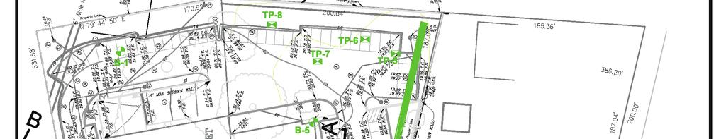
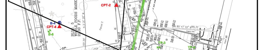
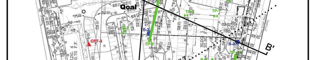


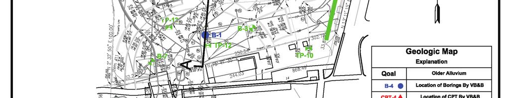
108
Date: April 2, 2014 Project No.: Prepared For: Mr. Adam Kates CLASSIC COMMUNITIES 1068 E. Meadow Circle Palo Alto, California 94303
 City of Newark - 36120 Ruschin Drive Project Draft Initial Study/Mitigated Negative Declaration Appendix C: Geologic Information FirstCarbon Solutions H:\Client (PN-JN)\4554\45540001\ISMND\45540001 36120
(THIS IS ONLY A SAMPLE REPORT OR APPENDIX OFFERED TO THE USERS OF THE COMPUTER PROGRAM
 C A U T I O N!! (THIS IS ONLY A SAMPLE REPORT OR APPENDIX OFFERED TO THE USERS OF THE COMPUTER PROGRAM EQLique&Settle2. THE AUTHOR IS HEREBY RELEASED OF ANY LIABILITY FOR ANY INCORRECT USE OF THIS SAMPLE
Liquefaction assessments of tailings facilities in low-seismic areas
 Page 1 Liquefaction assessments of tailings facilities in low-seismic areas Holly Rourke SRK Consulting, Perth, WA, Australia Caroline Holmes SRK Consulting, Perth, WA, Australia This paper was first presented
Use of CPT in Geotechnical Earthquake Engineering
 Use of CPT in Geotechnical Earthquake Engineering Prof. Scott M. Olson, PhD, PE Use of Cone Penetration Test for Foundation Analysis and Design 2006 Annual Meeting Transportation Research Board Geotechnical
Cone Penetration Test (CPT) Interpretation
 Interpretation") Cone Penetration Test (CPT) Interpretation Gregg uses a proprietary CPT interpretation and plotting software. The software takes the CPT data and performs basic interpretation in terms of soil behavior
Cone Penetration Test (CPT) Interpretation Gregg uses a proprietary CPT interpretation and plotting software. The software takes the CPT data and performs basic interpretation in terms of soil behavior
Evaluation of Geotechnical Hazards
 Evaluation of Geotechnical Hazards by Geoffrey R. Martin Appendix B: Evaluation of Geotechnical Hazards Describes Evaluation Procedures Soil Liquefaction Soil Settlement Surface Fault Rupture Flooding
Liquefaction-Induced Ground Deformations Evaluation Based on Cone Penetration Tests (CPT)
") World Journal of Engineering and Technology, 2014, 2, 249-259 Published Online November 2014 in SciRes. http://www.scirp.org/journal/wjet http://dx.doi.org/10.4236/wjet.2014.24026 Liquefaction-Induced
World Journal of Engineering and Technology, 2014, 2, 249-259 Published Online November 2014 in SciRes. http://www.scirp.org/journal/wjet http://dx.doi.org/10.4236/wjet.2014.24026 Liquefaction-Induced
EARTHQUAKE-INDUCED SETTLEMENTS IN SATURATED SANDY SOILS
 VOL., NO., AUGUST 7 ISSN 119- -7 Asian Research Publishing Network (ARPN). All rights reserved. EARTHQUAKE-INDUCED SETTLEMENTS IN SATURATED SANDY SOILS C. Y. Lee Department of Civil Engineering, College
1.1 Calculation methods of the liquefaction hazard.
 1 Theoretical basis 1.1 Calculation methods of the liquefaction hazard. 1.1.1 Empirical methods. Empirical methods are generally used to get a rough estimate of the liquefaction hazard in saturated sandy
Liquefaction Hazard Mapping. Keith L. Knudsen Senior Engineering Geologist California Geological Survey Seismic Hazard Mapping Program
 Liquefaction Hazard Mapping Keith L. Knudsen Senior Engineering Geologist California Geological Survey Seismic Hazard Mapping Program April 20, 2006 Topics Liquefaction hazard mapping (regional) CGS approach
Probabilistic evaluation of liquefaction-induced settlement mapping through multiscale random field models
 6 th Asian-Pacific Symposium on Structural Reliability and its Applications (APSSRA6) Probabilistic evaluation of liquefaction-induced settlement mapping through multiscale random field models Qiushi Chen
LIQUEFACTION ASSESSMENT OF INDUS SANDS USING SHEAR WAVE VELOCITY
 Pakistan Engineering Congress, 69th Annual Session Proceedings 219 LIQUEFACTION ASSESSMENT OF INDUS SANDS USING SHEAR WAVE VELOCITY Sohail Kibria 1, M. Javed 2, Muhammad Ali 3 ABSTRACT A host of procedures
THE OVERPREDICTION OF LIQUEFACTION HAZARD IN CERTAIN AREAS OF LOW TO MODERATE SEISMICITY
 THE OVERPREDICTION OF LIQUEFACTION HAZARD IN CERTAIN AREAS OF LOW TO MODERATE SEISMICITY Dr. Kevin Franke, Ph.D., P.E., M.ASCE Dept. of Civil and Environmental Engineering Brigham Young University April
Liquefaction Potential Post-Earthquake in Yogyakarta
 The 17 th Southeast Asian Geotechnical Conference Taipei, Taiwan, May 10~13, 2010 Liquefaction Potential Post-Earthquake in Yogyakarta AGUS SETYO MUNTOHAR 1 and S.P.R. WARDANI 2 1 Department of Civil Engineering,
Evaluation of soil liquefaction using the CPT Part 1
 Evaluation of soil liquefaction using the CPT Part 1 Dr. Peter K. Robertson Webinar #7 2013 CPT Guide 5 th Edition Download FREE copy from: Robertson & Cabal (Robertson) 5 th Edition 2012 www.greggdrilling.com
September 7, 2017 (Revised November 1, 2017)
") September 7, 2017 (Revised November 1, 2017) Project No. 10113.002 Environmental Advisors 2400 East Katella Avenue, Suite 800 Anaheim, California 92806 Attention: Subject: Mr. Greg McCafferty Response
September 7, 2017 (Revised November 1, 2017) Project No. 10113.002 Environmental Advisors 2400 East Katella Avenue, Suite 800 Anaheim, California 92806 Attention: Subject: Mr. Greg McCafferty Response
The LSN Calculation and Interpolation Process
 Appendix I : The LSN Calculation and Interpolation Process I1. Introduction Cone Penetration Tests (CPTs) can be used in the assessment of the liquefaction vulnerability. The CPTs available from the Canterbury
CPT-BASED SIMPLIFIED LIQUEFACTION ASSESSMENT BY USING FUZZY-NEURAL NETWORK
 326 Journal of Marine Science and Technology, Vol. 17, No. 4, pp. 326-331 (2009) CPT-BASED SIMPLIFIED LIQUEFACTION ASSESSMENT BY USING FUZZY-NEURAL NETWORK Shuh-Gi Chern* and Ching-Yinn Lee* Key words:
PHIMF Project - Limited Geotechnical Investigation - Feasibility-Level Report RESPONSE TO INITIAL REVIEW LETTER
 Connie Christian, P.E. County Sanitation Districts of Los Angeles County 1955 Workman Mill Road Whittier, California 90601 Project No. BAS 04-02E January 29, 2008 Subject: PHIMF Project - Limited Geotechnical
Liquefaction and Foundations
 Liquefaction and Foundations Amit Prashant Indian Institute of Technology Gandhinagar Short Course on Seismic Design of Reinforced Concrete Buildings 26 30 November, 2012 What is Liquefaction? Liquefaction
GEOTECHNICAL EXPLORATION REPORT ROPOSED COMMERCIAL/RETAIL DEVELOPMENT 7967, & 8015 BEVERLY BOULEVARD
 ADDENDUM TO GEOTECHNICAL EXPLORATION REPORT PROPOSED COMMERCIAL/RETAIL DEVELOPMENT 7967, 8001-8011 & 8015 BEVERLY BOULEVARD CITY OF LOS ANGELES, CALIFORNIA Prepared for: OPT Beverly, LLC 6400 South Fiddlers
RELATIONSHIP BETWEEN AGE OF GROUND AND LIQUEFACTION OCCURRENCE IN THE 2011 GREAT EAST JAPAN EARTHQUAKE
 Proceedings of the International Symposium on Engineering Lessons Learned from the 2011 Great East Japan Earthquake, March 1-4, 2012, Tokyo, Japan RELATIONSHIP BETWEEN AGE OF GROUND AND LIQUEFACTION OCCURRENCE
Soil Dynamics Prof. Deepankar Choudhury Department of Civil Engineering Indian Institute of Technology, Bombay
 Soil Dynamics Prof. Deepankar Choudhury Department of Civil Engineering Indian Institute of Technology, Bombay Module - 4 Dynamic Soil Properties Lecture - 23 Cyclic Stress Ratio, Evaluation of CRR, Correction
2-D Liquefaction Evaluation with Q4Mesh
 2005 Tri-Service Infrastructure Systems Conference and Exhibition 2-D Liquefaction Evaluation with Q4Mesh -David C. Serafini, M.S., P.E. US Army Corps, Sacramento, CA 3 August 2005 2005 Tri-Service ISC
Comparison of different methods for evaluating the liquefaction potential of sandy soils in Bandar Abbas
 Comparison of different methods for evaluating the liquefaction potential of sandy soils in Bandar Abbas M. Mosaffa¹ & M. Rafiee² 1.Geotechnical M.S. student Hormozgan University, Bandar Abbas, Iran(Email:Amestris@gmail.com).Geotechnical
GEOTECHNICAL STUDY RESIDENTIAL AND COMMERCIAL PROJECT th STREET OGDEN, UTAH
 GEOTECHNICAL STUDY RESIDENTIAL AND COMMERCIAL PROJECT 550 25 th STREET OGDEN, UTAH Prepared For: Mr. Chris Parker Ogden Community Investment Group 2604 Jefferson Avenue Ogden, Utah 84401 Prepared by: Summit
Assessment of the Potential for Earthquake- Induced Liquefaction in Granular Soils
 Spreadsheets in Education (ejsie) Volume 7 Issue Article 4 March 014 Assessment of the Potential for Earthquake- Induced Liquefaction in Granular Soils Salah Sadek American University of Beirut, salah@aub.edu.lb
Evaluation of the Liquefaction Potential by In-situ Tests and Laboratory Experiments In Complex Geological Conditions
 Evaluation of the Liquefaction Potential by In-situ Tests and Laboratory Experiments In Complex Geological Conditions V. Sesov, K. Edip & J. Cvetanovska University Ss. Cyril and Methodius, Institute of
Sensitivity of Liquefaction Triggering Analysis to Earthquake Magnitude
 Australian Earthquake Engineering Society 2013 Conference, Nov 15-17, Hobart, Tasmania Sensitivity of Liquefaction Triggering Analysis to Earthquake Magnitude Dr Timothy I Mote 1 and Minly M. L. So 2 1.
LSN a new methodology for characterising the effects of liquefaction in terms of relative land damage severity
 van Ballegooy, S., Lacrosse, V., Jacka, M. & Malan, P. (2013) Proc. 19 th NZGS Geotechnical Symposium. Ed. CY Chin, Queenstown LSN a new methodology for characterising the effects of liquefaction in terms
Evaluation of liquefaction resistance of non-plastic silt from mini-cone calibration chamber tests
 Evaluation of liquefaction resistance of non-plastic silt from mini-cone calibration chamber tests C.D.P. Baxter, M.S. Ravi Sharma, N.V. Seher, & M. Jander University of Rhode Island, Narragansett, USA
Guidelines for Site-Specific Seismic Hazard Reports for Essential and Hazardous Facilities and Major and Special-Occupancy Structures in Oregon
 Guidelines for Site-Specific Seismic Hazard Reports for Essential and Hazardous Facilities and Major and Special-Occupancy Structures in Oregon By the Oregon Board of Geologist Examiners and the Oregon
Roy Pyle March 24, 2017 Chief Facilities Planner Contra Costa Community College District 500 North Court Street Martinez, CA 94533
 State of California Natural Resources Agency Edmund G. Brown Jr., Governor Department of Conservation John G. Parrish, Ph.D., State Geologist California Geological Survey 801 K Street MS 12-31 Sacramento,
Case History of Observed Liquefaction-Induced Settlement Versus Predicted Settlement
 Case History of Observed Liquefaction-Induced Settlement Versus Predicted Settlement M. Lew and L. Tran AMEC Environment & Infrastructure, Inc., Los Angeles, CA USA SUMMARY: A comparison of the predicted
Should you have any questions regarding this clarification, please contact the undersigned at or (925)
") October 8, 2015 Revised October 13, 2015 Contra Costa Community College District 500 Court Street Martinez, CA 94553 Attention: Ron Johnson Subject: Clarification of Grading Requirements Diablo Valley
October 8, 2015 Revised October 13, 2015 Contra Costa Community College District 500 Court Street Martinez, CA 94553 Attention: Ron Johnson Subject: Clarification of Grading Requirements Diablo Valley
LIQUEFACTION POTENTIAL & POST EARTHQUAKE STABILITY ASSESSMENT. H2J Engineering
 LIQUEFACTION POTENTIAL & POST EARTHQUAKE STABILITY ASSESSMENT Project ID: CEEn_16CPST_13 by H2J Engineering Project Mentor: Tyler Coutu Team Lead: Heidi Decayanan Equipment Specialist: Joshua Peterson
Liquefaction Evaluation
 Liquefaction Evaluation Ahmed Elgamal and Zhaohui Yang University of California, San Diego Acknowledgements The Liquefaction Evaluation section is prepared mainly following: Kramer, S. L. (1996). Geotechnical
Liquefaction Risk Potential of Road Foundation in the Gold Coast Region, Australia
 Liquefaction Risk Potential of Road Foundation in the Gold Coast Region, Australia Author Mosavat, Nasim, Oh, Erwin, Chai, Gary Published 2013 Journal Title Electronic Journal of Geotechnical Engineering
Improved Liquefaction Hazard Evaluation through PLHA. Steven L. Kramer University of Washington
 Improved Liquefaction Hazard Evaluation through PLHA Steven L. Kramer University of Washington il Liquefaction hree primary questions to answer: Is the soil susceptible to liquefaction? If so, is the anticipated
SUMMARY OF SOIL CONDITIONS CITYWIDE SIDEWALK IMPROVEMENT PROJECT JIMMY DURANTE BOULEVARD, VIA DE LA VALLE, AND CAMINO DEL MAR DEL MAR, CALIFORNIA
 SUMMARY OF SOIL CONDITIONS CITYWIDE SIDEWALK IMPROVEMENT PROJECT JIMMY DURANTE BOULEVARD, VIA DE LA VALLE, AND CAMINO DEL MAR DEL MAR, CALIFORNIA PREPARED FOR NASLAND ENGINEERING SAN DIEGO, CALIFORNIA
A comparison between two field methods of evaluation of liquefaction potential in the Bandar Abbas City
 American Journal of Civil Engineering 2015; 3(2-2): 1-5 Published online January 16, 2015 (http://www.sciencepublishinggroup.com/j/ajce) doi: 10.11648/j.ajce.s.2015030202.11 ISSN: 2330-8729 (Print); ISSN:
Evaluating Soil Liquefaction and Post-earthquake deformations using the CPT
 Evaluating Soil Liquefaction and Post-earthquake deformations using the CPT P.K. Robertson University of Alberta, Dept. of Civil and Environmental Engineering, Edmonton, Canada Keywords: Soil liquefaction,
Paleoseismic Investigations for Determining the Design Ground Motions for Nuclear Power Plants
 Paleoseismic Investigations for Determining the Design Ground Motions for Nuclear Power Plants Russell A. Green Department of Civil and Environmental Engineering Purdue Geotechnical Society Workshop May
CPT: Geopractica Contracting (Pty) Ltd Total depth: m, Date:
 Ltd Total depth: m, Date:") The plot below presents the cross correlation coeficient between the raw qc and fs values (as measured on the field). X axes presents the lag distance (one lag is the distance between two sucessive CPT
The plot below presents the cross correlation coeficient between the raw qc and fs values (as measured on the field). X axes presents the lag distance (one lag is the distance between two sucessive CPT
Bayesian Methods and Liquefaction
 Bayesian Methods and Liquefaction John T. Christian Consulting Engineer, 36E Seven Springs Lane, Burlington, MA 01803, USA Gregory B. Baecher Prof., Dept. of Civil and Env. Engineering, University of Maryland,
Determination of Liquefaction Potential By Sub-Surface Exploration Using Standard Penetration Test
 Determination of Liquefaction Potential By Sub-Surface Exploration Using Standard Penetration Test 1 Sabih Ahmad, 2 M.Z.Khan, 3 Abdullah Anwar and 4 Syed Mohd. Ashraf Husain 1 Associate Professor and Head,
Liquefaction Potential Variations Influenced by Building Constructions
 Earth Science Research; Vol. 1, No. 2; 2012 ISSN 1927-0542 E-ISSN 1927-0550 Published by Canadian Center of Science and Education Liquefaction Potential Variations Influenced by Building Constructions
Liquefaction Evaluations at the Savannah River Site. A Case History
 Missouri University of Science and Technology Scholars' Mine International Conference on Case Histories in Geotechnical Engineering (2004) - Fifth International Conference on Case Histories in Geotechnical
Guidance for the CPT-Based Assessment of Earthquakeinduced Liquefaction Potential in Australia, with a Focus on the Queensland Coast
 Guidance for the CPT-Based Assessment of Earthquakeinduced Liquefaction Potential in Australia, with a Focus on the Queensland Coast Tim Thompson CPEng RPEQ PE Senior Engineer Arup 108 Wickham Street,
LIQUEFACTION CHARACTERISTICS EVALUATION THROUGH DIFFERENT STRESS-BASED MODELS: A COMPARATIVE STUDY
 Journal of Engineering Research and Studies E-ISSN976-7916 Research Article LIQUEFACTION CHARACTERISTICS EVALUATION THROUGH DIFFERENT STRESS-BASED MODELS: A COMPARATIVE STUDY P. Raychowdhury 1* and P.
NEW METHOD FOR LIQUEFACTION ASSESSMENT BASED ON SOIL GRADATION AND RELATIVE DENSITY
 NEW METHOD FOR LIQUEFACTION ASSESSMENT BASED ON SOIL GRADATION AND RELATIVE DENSITY Bambang Istijono 1, Abdul Hakam 2 1,2 Civil Dept. of Engineering Faculty, University of Andalas, Padang, Indonesia ABSTRACT
CPT Data Interpretation Theory Manual
 CPT Data Interpretation Theory Manual 2016 Rocscience Inc. Table of Contents 1 Introduction... 3 2 Soil Parameter Interpretation... 5 3 Soil Profiling... 11 3.1 Non-Normalized SBT Charts... 11 3.2 Normalized
Ground Motions and Liquefaction Potential
 Missouri University of Science and Technology Scholars' Mine International Conferences on Recent Advances in Geotechnical Earthquake Engineering and Soil Dynamics 2010 - Fifth International Conference
PROCEDURE TO EVALUATE LIQUEFACTIO -I DUCED SETTLEME T BASED O SHEAR WAVE VELOCITY. Fred (Feng) Yi 1 ABSTRACT
 Yi 1 ABSTRACT") PROCEDURE TO EVALUATE LIQUEFACTIO -I DUCED SETTLEME T BASED O SHEAR WAVE VELOCITY Fred (Feng) Yi 1 ABSTRACT As a major geologic hazard, evaluation of liquefaction-induced settlement is very important for
PROCEDURE TO EVALUATE LIQUEFACTIO -I DUCED SETTLEME T BASED O SHEAR WAVE VELOCITY Fred (Feng) Yi 1 ABSTRACT As a major geologic hazard, evaluation of liquefaction-induced settlement is very important for
Assessment of Risk of Liquefaction - A Case Study
 Assessment of Risk of Liquefaction - A Case Study ASHWAI JAI Deptt. of Civil Engineering ational Institute Technology Kurukshetra-136119 IDIA ashwani.jain66@yahoo.com Abstract: - Catastrophic failures
SOME OBSERVATIONS RELATED TO LIQUEFACTION SUSCEPTIBILITY OF SILTY SOILS
 SOME OBSERVATIONS RELATED TO LIQUEFACTION SUSCEPTIBILITY OF SILTY SOILS Upul ATUKORALA 1, Dharma WIJEWICKREME 2 And Norman MCCAMMON 3 SUMMARY The liquefaction susceptibility of silty soils has not received
WORKSHOP ON PENETRATION TESTING AND OTHER GEOMECHANICAL ISSUES Pisa 14 June 2016 ROOM F8
 WORKSHOP ON PENETRATION TESTING AND OTHER GEOMECHANICAL ISSUES Pisa 14 June 2016 ROOM F8 LIQUEFACTION PHOENOMENA DURING THE EMILIA SEISMIC SEQUENCE OF 2012 AND THE LIQUEFACTION POTENTIAL FROM A LARGE DATABASE
QUAKE/W ProShake Comparison
 1 Introduction QUAKE/W Comparison is a commercially available software product for doing one-dimensional ground response analyses. It was developed and is being maintained under the guidance of Professor
LIQUEFACTION POTENTIAL ASSESSMENT BASED ON LABORATORY TEST
 Geotec., Const. Mat. & Env., ISSN: 2186-2982(Print), 2186-299(Online), Japan LIQUEFACTION POTENTIAL ASSESSMENT BASED ON LABORATORY TEST Abdul Hakam 1, Febrin Anas Ismail 1 and Fauzan 1 1 CivilEngineering,
Semi-empirical procedures for evaluating liquefaction potential during earthquakes
 Soil Dynamics and Earthquake Engineering 26 (26) 5 3 www.elsevier.com/locate/soildyn Semi-empirical procedures for evaluating liquefaction potential during earthquakes I.M. Idriss, R.W. Boulanger* Department
Micro Seismic Hazard Analysis
 Micro Seismic Hazard Analysis Mark van der Meijde INTERNATIONAL INSTITUTE FOR GEO-INFORMATION SCIENCE AND EARTH OBSERVATION Overview Site effects Soft ground effect Topographic effect Liquefaction Methods
Liquefaction. Ajanta Sachan. Assistant Professor Civil Engineering IIT Gandhinagar. Why does the Liquefaction occur?
 Liquefaction Ajanta Sachan Assistant Professor Civil Engineering IIT Gandhinagar Liquefaction What is Liquefaction? Why does the Liquefaction occur? When has Liquefaction occurred in the past? Where does
Presentation Outline. 1. Seismic Soil Liquefaction Explained 2. Presentation of the Software SOILLIQ 3. Illustrative Applications using SOILLIQ
 Presentation Outline 1. Seismic Soil Liquefaction Explained 2. Presentation of the Software SOILLIQ 3. Illustrative Applications using SOILLIQ Foundation Failures in Residential Buildings (1964 Niigata,
FRIENDS OF THE EEL RIVER
 FRIENDS OF THE EEL RIVER Working for the recovery of our Wild & Scenic River, its fisheries and communities. Frank Blackett, Regional Engineer Office of Energy Projects Division of Dam Safety and Inspections
A CASE STUDY OF LIQUEFACTION ASSESSMENT USING SWEDISH WEIGHT SOUNDING
 4th International Conference on Earthquake Engineering Taipei, Taiwan October 12-13, 2006 Paper No. 038 A CASE STUDY OF LIQUEFACTION ASSESSMENT USING SWEDISH WEIGHT SOUNDING Mahdi Habibi 1, Akbar Cheshomi
Converse Consultants Geotechnical Engineering, Environmental & Groundwater Science, Inspection & Testing Services
 Converse Consultants Geotechnical Engineering, Environmental & Groundwater Science, Inspection & Testing Services Ms. Rebecca Mitchell Mt. San Antonio College Facilities Planning & Management 1100 North
SIMPLIFIED METHOD IN EVALUATING LIQUEFACTION OCCURRENCE AGAINST HUGE OCEAN TRENCH EARTHQUAKE
 October 12-17, 28, Beijing, China SIMPLIFIED METHOD IN EVALUATING LIQUEFACTION OCCURRENCE AGAINST HUGE OCEAN TRENCH EARTHQUAKE ABSTRACT : N. Yoshida 1, S. Sawada 2 and S. Nakamura 3 1 Professor, Dept.
Session 2: Triggering of Liquefaction
 Session 2: Triggering of Liquefaction Plenary Speaker: Geoff Martin Professor Emeritus University of Southern California What are the primary deficiencies in the simplified method for evaluation of liquefaction
Comparison of Three Procedures for Evaluating Earthquake-Induced Soil Liquefaction
 Missouri University of Science and Technology Scholars' Mine International Conferences on Recent Advances in Geotechnical Earthquake Engineering and Soil Dynamics 2010 - Fifth International Conference
Performance based earthquake design using the CPT
 Performance based earthquake design using the CPT P.K. Robertson Gregg Drilling & Testing Inc., Signal Hill, California, USA Performance-Based Design in Earthquake Geotechnical Engineering Kokusho, Tsukamoto
Station Description Sheet GRA
 Station Description Sheet GRA 1. General Information 2. Geographical Information / Geomorphology 3. Geological Information 4. Geotechnical Site Characterization 5. Geophysical Site Characterization 6.
Characterization of Liquefaction Resistance in Gravelly Soil : Large Hammer Penetration Test and Shear Wave Velocity Approach
 Characterization of Liquefaction Resistance in Gravelly Soil : Large Hammer Penetration Test and Shear Wave Velocity Approach Ping-Sien Lin *,1, Chi-Wen Chang 1, Wen-Jong Chang 2 1 Department of Civil
Behavior of Soft Riva Clay under High Cyclic Stresses
 Behavior of Soft Riva Clay under High Cyclic Stresses Mustafa Kalafat Research Assistant, Boğaziçi University, Istanbul, Turkey; mkalafat@boun.edu.tr Canan Emrem, Ph.D., Senior Engineer, ZETAS Zemin Teknolojisi
Evaluation of soil liquefaction using the CPT Part 2
 Evaluation of soil liquefaction using the CPT Part 2 P.K. Robertson 2013 Definitions of Liquefaction Cyclic (seismic) Liquefaction Zero effective stress (during cyclic loading) Flow (static) Liquefaction
CPT Applications - Liquefaction 2
 CPT Applications - Liquefaction 2 Peter K. Robertson CPT in Geotechnical Practice Santiago, Chile July, 2014 Definitions of Liquefaction Cyclic (seismic) Liquefaction Zero effective stress (during cyclic
Class Principles of Foundation Engineering CEE430/530
 Class Principles of Foundation Engineering CEE430/530 1-1 General Information Lecturer: Scott A. Barnhill, P.E. Lecture Time: Thursday, 7:10 pm to 9:50 pm Classroom: Kaufmann, Room 224 Office Hour: I have
This document downloaded from vulcanhammer.net vulcanhammer.info Chet Aero Marine
 This document downloaded from vulcanhammer.net vulcanhammer.info Chet Aero Marine Don t forget to visit our companion site http://www.vulcanhammer.org Use subject to the terms and conditions of the respective
CHAPTER 3 LITERATURE REVIEW ON LIQUEFACTION ANALYSIS OF GROUND REINFORCEMENT SYSTEM
 CHAPTER 3 LITERATURE REVIEW ON LIQUEFACTION ANALYSIS OF GROUND REINFORCEMENT SYSTEM 3.1 The Simplified Procedure for Liquefaction Evaluation The Simplified Procedure wa firt propoed by Seed and Idri (1971).
ADDENDUM No.1 GEOTECHNICAL INVESTIGATION REPORT PLAZA MEXICO RESIDENCES 3000 E Imperial Highway Lynwood, California
 Mr. Luis Valenzuela M&D Properties 3100 E Imperial Highway Lynwood, CA 90262 Project No. TET 16-93E June 16, 2017 Subject: ADDENDUM No.1 GEOTECHNICAL INVESTIGATION REPORT PLAZA MEXICO RESIDENCES 3000 E
Numerical analysis of effect of mitigation measures on seismic performance of a liquefiable tailings dam foundation
 Numerical analysis of effect of mitigation measures on seismic performance of a liquefiable tailings dam foundation Yong-Beom Lee, Jorge Castillo Ausenco, USA Aurelian C. Trandafir Fugro GeoConsulting
GEOTECHNICAL SEISMIC HAZARDS
 Chapter 13 GEOTECHNICAL SEISMIC HAZARDS FINAL SCDOT GEOTECHNICAL DESIGN MANUAL June 2010 Table of Contents Section Page 13.1 Introduction... 13-1 13.2 Geotechnical Seismic Hazard Failure Modes... 13-2
An application of liquefaction hazard evaluation in urban planning
 An application of liquefaction hazard evaluation in urban planning Clive Anderson Principal Geotechnical Engineer, URS New Zealand Limited, 287 Durham Street, Christchurch, New Zealand Tim McMorran Senior
Seismic Geotechnical Hazard Zonation Of Geological Factors
 1 st Workshop of M.E.E.T.I.N.G Project Seismic Geotechnical Hazard Zonation Of Geological Factors Maja Oštri, dipl.ing.geol Dubrovnik, March 3rd-4th 2008 SUBJECT OF THE INVESTIGATION? Geological Factors
Liquefaction potential of Rotorua soils
 Pearse-Danker, E. (2013) Liquefaction potential of Rotorua soils Proc. 19 th NZGS Geotechnical Symposium. Ed. CY Chin, Queenstown Liquefaction potential of Rotorua soils E Pearse-Danker Coffey Geotechnics
Comparison of CPTu and SDMT after 2012 Samara Earthquake, Costa Rica: liquefaction case studies
 Comparison of CPTu and SDMT after 2012 Samara Earthquake, Costa Rica: liquefaction case studies S. Amoroso INGV Istituto Nazionale di Geofisica e Vulcanologia, L'Aquila, Italy P. Monaco University of L'Aquila,
Evaluation of Settlement in Soil Layers due to Liquefaction in Alluviums in South Eastern of Tehran
 ORIGINAL ARTICLE PII: S537-7 Received 3 May. 7 Accepted 9 Aug. 7 7 Scienceline Publication Journal of Civil Engineering and Urbanism Volume 7, Issue 5: 7-79; Sep 5, 7 ISSN-5-3 Evaluation of Settlement
Liquefaction-induced ground and foundation displacements have
 Updating Assessment Procedures and Developing a Screening Guide for Liquefaction by T. Leslie Youd, Brigham Young University Research Objectives The main objectives of this research program are to provide
Prediction of earthquake-induced liquefaction for level and gently
 Chiaro, G. & Koseki, J. (21) Proc. 1 th NZGS Geotechnical Symposium. Ed. CY Chin, Queenstown Prediction of earthquake-induced liquefaction for level and gently sloped ground G Chiaro Centre for Geomechanics
 www.novotechsoftware.com The standard penetration test (SPT) is an in-situ dynamic penetration test designed to provide information on the geotechnical engineering properties of soil. The test procedure
SLOPE STABILITY EVALUATION AND ACCEPTANCE STANDARDS
 INFORMATION BULLETIN / PUBLIC - BUILDING CODE REFERENCE NO.: LAMC 98.0508 Effective: 1-26-84 DOCUMENT NO. P/BC 2002-049 Revised: 11-1-02 Previously Issued As: RGA #1-84 SLOPE STABILITY EVALUATION AND ACCEPTANCE
A SPT BASED COMPARATIVE ANALYSIS OF LIQUEFACTION POTENTIAL OF RAPTI MAIN CANAL IN DISTRICT BALRAMPUR
 IMPACT: International Journal of Research in Engineering & Technology (IMPACT: IJRET) ISSN(E): 2347-4599; ISSN(P): 2321-8843 Vol. 3, Issue 11, Nov 2015, 11-22 Impact Journals A SPT BASED COMPARATIVE ANALYSIS
Using GIS Software for Identification and Zoning of the Areas Prone to Liquefaction in the Bed Soil of the Dams
 Indian Journal of Science and Technology, Vol 8(S9), 62-66, May 2015 ISSN (Print) : 0974-6846 ISSN (Online) : 0974-5645 DOI: 10.17485/ijst/2015/v8iS9/68555 Using GIS Software for Identification and Zoning
APPENDIX C GEOTECHNICAL EXPLORATION REPORT AND RESPONSE TO CGS REVIEW COMMENTS
 APPENDIX C GEOTECHNICAL EXPLORATION REPORT AND RESPONSE TO CGS REVIEW COMMENTS SAN FRANCISO UNIFIED SCHOOL DISTRICT CLAIRE LILIENTHAL (SCOTT CAMPUS) 3-8 SCHOOL NEW CLASSROOM AND GYMNASIUM BUILDING AND
Liquefaction Hazards for Seismic Risk Analysis
 Liquefaction Hazards for Seismic Risk Analysis S. Giovinazzi & M. Cubrinovski University of Canterbury, Christchurch, New Zealand. 2007 NZSEE Conference ABSTRACT: Seismic risk analysis is a helpful tool
Numerical modeling of liquefaction effects: Development & initial applications of a sand plasticity model
 4 th IASPEI / IAEE International Symposium Santa Barbara, California, Aug 23-26, 2011 Numerical modeling of liquefaction effects: Development & initial applications of a sand plasticity model Ross W. Boulanger
IV. ENVIRONMENTAL IMPACT ANALYSIS G. GEOLOGY AND SOILS
 IV. ENVIRONMENTAL IMPACT ANALYSIS G. GEOLOGY AND SOILS The following section is a summary of the geotechnical report conducted for the proposed project. The Report of Geotechnical Investigation Proposed
CONE PENETRATION TEST DATA
 CONE PENETRATION TEST DATA Proposed Logan Water Treatment Plant Addition Logan, Utah January 25, 203 Prepared for: IGES, Inc. Salt Lake City, Utah Prepared by: ConeTec, Inc. Salt Lake City, Utah January
DIFFICULTIES IN ASSESSING LIQUEFACTION POTENTIAL FROM CONVENTIONAL FIELD TESTING
 DIFFICULTIES IN ASSESSING LIQUEFACTION POTENTIAL FROM CONVENTIONAL FIELD TESTING Dr. Peter W. Mitchell 1 and Carly Moore 2 1. BEng MEng PhD CPEng MIEAust, Senior Principal Geotechnical Engineer, URS Australia
Estimation of Shear Wave Velocity Using Correlations
 Estimation of Shear Wave Velocity Using Correlations Pranav Badrakia P.G. Student, Department of Civil Engineering, Maharashtra Institute of Technology, Pune, Maharashtra, India 1 ABSTRACT: Shear wave
LIQUEFACTION ASSESSMENT BY THE ENERGY METHOD THROUGH CENTRIFUGE MODELING
 LIQUEFACTION ASSESSMENT BY THE ENERGY METHOD THROUGH CENTRIFUGE MODELING Hesham M. Dief, Associate Professor, Civil Engineering Department, Zagazig University, Zagazig, Egypt J. Ludwig Figueroa, Professor