Three-Dimensional Penetration and Velocity Distribution of Liquid Jets Injected Transversely into a Swirling Crossflow
|
|
|
- Neal Warren
- 5 years ago
- Views:
Transcription
1 ILASS Americas, 22 nd Annual Conference on Liquid Atomization and Spray Systems, Cincinnati, OH, May 2010 Three-Dimensional Penetration and Velocity Distribution of Liquid Jets Injected Transversely into a Swirling Crossflow Samir B Tambe * and San-Mou Jeng Department of Aerospace Engineering and Engineering Mechanics University of Cincinnati Cincinnati, OH USA Abstract An experimental study has been conducted to study the effect of a swirling crossflow on transversely injected liquid jets. In-house designed axial swirlers with vane exit angles of 30, 45 and 60 were used to generate the swirling crossflow. Laser Doppler Velocimetry (LDV) results indicate that the axial (U x ) and the tangential (U θ ) components of the crossflow velocity decrease with increasing radial distance from the center. Also, flow angle (ψ) of the crossflow is lesser than the swirler vane exit angle indicating that the swirlers did not impart sufficient tangential momentum for the flow to be parallel to the vanes at swirler exit. The deficit in flow angle increased with swirler angle. Water jets were injected from a 0.5 mm diameter orifice located on a cylindrical centerbody that protruded through the hub of the swirler. Particle Image Velocimetry (PIV) was used to study the behavior of the jets. PIV measurements were conducted in multiple cross-sectional and streamwise planes. Mie-Scattering images were collated to create three-dimensional representation of the jet plume, which was used to study penetration. In cylindrical coordinate system, the penetration can be described in terms of radial and circumferential penetration, where circumferential penetration is defined as the difference in the circumferential displacement of the jet and the crossflow over the same streamwise displacement. Increasing the momentum flux ratio (q) resulted in a higher radial penetration. Increasing the swirl angle reduced radial penetration and increased circumferential penetration. PIV results of the cross-sectional and streamwise planes each yielded two velocity components which were merged to obtain threedimensional droplet velocity distribution. The three-dimensional velocity distribution yielded further insight into the evolution of the jet plume. * Corresponding author


2 ILASS Americas, 22 nd Annual Conference on Liquid Atomization and Spray Systems, Cincinnati, OH, May 2010 Introduction The transversely injected liquid jet in crossflow has numerous applications including fuel injection [1], thrust vector control of rockets [2], and lubrication of the bearing chamber [3]. The injection of a liquid fuel jet into crossflow is also one of several possible concepts of a premix module for lean, premixed, prevaporized (LPP) combustion for aviation gas turbines. The demands for higher efficiency of power production and smaller engines lead to an increase in the operating temperatures and pressures. This leads to increase in the production of effluents like oxides of nitrogen (NO x ) since NO x formation rates increase with temperature [4]. With the increasingly stricter ICAO regulations on engine emissions, there is a strong emphasis on the development of low-emission combustion techniques. One technique is the LPP combustion, where lean, homogeneous fuel-air mixture is created just upstream of the combustor inlet. The presence of excess air throughout the primary zone ensures that the combustion temperature is low enough to suppress NO x formation. The LPP model requires a premix duct where fuel and air are mixed together. To achieve good homogeneous mixture and to avoid coking, fine atomization and careful fuel placement are needed. Liquid jet in crossflow has characteristics of rapid atomization and controllable penetration [1], which make it a good choice for LPP fuel injection. Jet-in-crossflow is a fundamental flow field and has been the subject of numerous experimental as well as computational studies. Tambe [5] and Elshamy [6] have conducted detailed literature reviews of the work done in this area. However, most of the studies feature uniform crossflows, i.e. where crossflow velocity does not change in the transverse direction. Only a few studies have utilized crossflows with steady-state nonuniform velocity profiles. Becker and Hassa [7, 8] injected liquid jets into a counter-swirling double-annular crossflow and studied the effect of momentum flux ratio and air pressure on the jet behavior. Gong et al [9] published a preliminary report on studies conducted for the Lean Direct Wall Injection (LDWI) concept, where they injected liquid jets into a swirling flow at different injection angles. The authors previously conducted a study where jets were injected transversely into a crossflow laden with a shear layer [10, 11]. The shear layer was generated by creating a slip plane between two co-flowing airstreams, creating a quasi-linear velocity gradient in the transverse direction. The strength of the shear layer and the sense of the velocity gradient had a significant impact on the jet penetration and the post-breakup spray. The objective of the present work is to study the behavior of a liquid jet injected transversely into a swirling crossflow. The effect of swirl strength, in addition to typical jet parameters, on the jet penetration and the droplet velocity distribution was investigated. The swirl strength was varied by using three different axial swirlers with different vane exit angles. Experimental techniques used include Laser Doppler Velocimetry (LDV) and 2-D Particle image Velocimetry (PIV). The study was divided into a thorough investigation of the crossflow before looking at jets and the impact of this crossflow on their behavior. A part of this study [12] was reported previously. This paper serves to extend the findings from the previous paper. In this study, LDV was used to study the crossflow to avoid the signal-to-noise issues experienced during PIV measurements [12]. PIV measurements were conducted on the jet at multiple cross-sectional as well as streamwise planes. The Mie-Scattering images from the cross-sectional planes led to an improved penetration prediction. Also, as each plane yielded two components of droplet velocity, the results were combined to create three-dimensional droplet velocity distribution. b) a) Figure 1. Test Chamber, a) Model, b) Test Chamber. Experimental Setup Test Chamber The test chamber has a square cross-section with an internal dimension of 7.62 cm (3 ) and is cm (12 ) long. The walls of the test chamber are constructed of mm (1/8 ) thick acrylic material for maximum optical access. The walls are mounted on aluminum corner struts, which also provide a chamfer to suppress corner recirculation zones. Figure 1a shows a model of the test chamber assembly and also indicates the coordinate frame of reference used for all analysis. Figure 1b shows the test chamber. The origin of the coordinate frame is located on the axis of the centerbody at the streamwise location of the center of the jet orifice. X-axis is aligned with the


3 streamwise direction, Y-axis points vertically upwards and Z-axis points to the left as viewed from downstream. The test chamber assembly is mounted onto the Horizontal Rig, which is one of the experimental rigs available at the Combustion Diagnostics Research Laboratory at the University of Cincinnati s Center Hill Facility. The Horizontal Rig is a long pipe cm (6 ) in diameter, and is equipped with a 72 kw inline air heater (not used for this study). A computer controlled 3-axis Lintech traverse is provided for precise positioning of diagnostic equipment. Air is provided from a Kaesar variable speed rotary compressor capable of maximum flow rate of kg/s (2 lb/s) at a pressure of 7.9 bars (100 psig), connected to a dryer and tanks. A network of cm (4 ) and 5.08 cm (2 ) diameter pipes connects the air tanks to the Horizontal Rig. Air flow rate is metered by a Micro Motion CMF300 coriolis flowmeter and controlled by a standard gate valve. Jet injection is carried out through a centerbody, which protrudes from the swirler hub and extends through the length of the test chamber. The centerbody is a 1.91 cm (3/4 ) outer diameter stainless steel tube with wall thickness of 1.65 mm (0.065 ). Thus the radius of the centerbody, r cb = 0.96 cm. A water jet is injected from a 0.5 mm orifice located 2.54 cm (1 ) downstream of the swirler exit. The centerbody is aligned so that the jet orifice is centered on the Y-axis. Thus the coordinates of the center of the orifice are (0, r cb, 0). The injected liquid is water, and is housed in a water tank. A nitrogen cylinder is used to pressurize the water tank, in order to drive the flow, as well as maintain a constant flow rate. The water flow rate is measured by a Micro Motion CMF010 coriolis flowmeter. A Parker metering valve is used for precise control of the water flow rate. Figure 2 shows a schematic of the experimental setup. Swirlers The axial swirlers used for the study were designed in-house and were fabricated by Rapid Prototyping SLA technology. The swirlers feature a hub diameter of 2.22 cm (0.875 ) and a tip diameter of 7.62 cm (3 ). A 1.91 cm (3/4 ) diameter hole is provided in the hub to accommodate the centerbody. Three different swirlers were used, with vane exit angles of 30, 45 and 60. The swirlers have a streamwise depth of 2.54 cm (1 ) with 12 vanes each for the 45 and 60 swirlers. To achieve reasonable solidity, the number of vanes was increased to 16 for the 30 swirler. The vanes were radial, and designed to provide a smooth transition from axial direction to the vane exit angle. Figure 3 shows a cutout of the 45 swirler design model as well as a fabricated swirler. All swirlers induce a swirl in the clockwise direction, as viewed from downstream. Figure 2. Schematic of Experimental Setup. a) b) Figure Axial Swirler, a) Model, b) Swirler. Measurement Techniques LDV measurements were conducted to characterize the crossflow. The equipment used for LDV measurements is the PDI-200 from Artium Inc. The PDI-200 series consists of a transmitter, a receiver, a power supply for the transmitter, and signal processing system. The special feature of the PDI-200 system is that the lasers are housed within the transmitter itself, so that there is no need for fiber optic systems, and the related alignment issues. The lasers used are Diode Pumped Solid State (DPSS) lasers, which do not require active cooling, and hence can be housed within a compact transmitter body. The PDI system was operated in LDV mode with forward scatter at an angle of 15. The crossflow was seeded with olive oil droplets to enable measurement. For each test case, measurements were conducted in a cross-sectional plane 2.54 cm (1 ) downstream of the jet injection (x = 2.54 cm). Figure 4 shows a schematic of the setup for the LDV measurements. 2-D PIV was used for jet flow measurements. The PIV system is a LaVision commercial PIV system. A NewWave Solo PIV, double-pulsed Nd:YAG laser emits laser pulses at a wavelength of 532 nm with a maximum energy of 120 mj/pulse. A LaVision Image Intense, double frame - double exposure CCD camera acquires images at the rate of 5 image pairs per second. A bandpass filter at 532 ± 3 nm is used to restrict the
 45 33.91 0.222 50.67 38.95 63.91 37.5 C3 60 25.98 0.175 40.37 39.13 56.22 44.1 C4 60 49.35 0.24 55.41 54.12 77.46 44.3 ψ = f(r) 2 φ cf,20 (deg), r = 20 mm, Δx = 20 mm ψ = 0.")

4 Case no Swirler ILASS Americas, 22 nd Annual Conference on Liquid Atomization and Spray Systems, Cincinnati, OH, May 2010 We m cf (kg/s) U x (m/s) U θ (m/s) U (m/s) ψ (deg) C C2 (base) C C ψ = f(r) 2 φ cf,20 (deg), r = 20 mm, Δx = 20 mm ψ = r+ 8.6, R = ψ = r+ 9.7, R = ψ = r+ 11, R = ψ = r+ 12.2, R = Table 1. Test conditions and relevant parameters for crossflow studies. light absorbed to the laser wavelength. For more details on the PIV system, please refer to Elshamy [6]. The centerbody was coated with a fluorescent paint to reduce noise due to reflection. The paint converts about 30% of the green laser light into red fluorescent light, which gets blocked by the bandpass filter on the camera. Figure 5 shows the schematic of the PIV for measurement in the x = constant planes. Figure 4. Schematic of LDV Setup. Figure 5. Schematic of PIV Setup. PIV measurements were conducted in crosssectional planes, i.e. parallel to the YZ plane (x = constant). Measurement was conducted over a range of x = 0:25 mm, with a spacing of 2.5 mm between measurement planes. Additionally, a few of the cases were repeated with measurements in streamwise planes, i.e. parallel to the XY plane (z = constant). The measured domain was z = 0:-30 with the planes separated by 2.5 mm. Test conditions The 45 swirler was considered as the base swirler. Table 1 lists the test conditions used for crossflow studies. Table 2 lists the test conditions for jet measurements for cross-sectional (x = constant) as well as streamwise (z = constant) planes. The test cases for jets were designed so that the streamwise planes would repeat the test conditions for the cross-sectional planes. Thus cross-sectional and streamwise measurements for case J3 are represented by cases J3c and J3s respectively. The base cases for the crossflow and the jet are cases C2 and J3. The Weber number (We) and the momentum flux ratio (q) described in the test conditions were calculated based on total crossflow velocity, which was obtained from LDV results as explained in the results section. For water, a density of 996 kg/m 3 and a surface tension of N/m have been assumed. Results and Discussion Note on Polar domain Since the nature of the crossflow is axisymmetric, it was considered more useful to analyze the flow in a cylindrical domain. However, since all measurements are conducted in cartesian planes, the measured domains need to be transformed. The process occurs in a x = constant plane, where (y, z) coordinates are transformed into (r, θ) coordinates (Figure 6). A new polar grid was created, and properties at the new grid points were obtained by interpolation. The polar grid, along with the X-axis, completes the cylindrical domain. Also, since the jet orifice is located on the 12 o clock position on the centerbody, the circumferential coordinate is oriented such that θ = 0 at the positive Y-axis and increases in the clockwise direction, as seen from downstream.
 45 83.")
, x = 20 mm J7c 60 51.56 39.16 0.243 57.28 55.95 80.07 0.201 17.")
5 ILASS Americas, 22 nd Annual Conference on Liquid Atomization and Spray Systems, Cincinnati, OH, May 2010 Case No Swirler We q m cf (kg/s) U x (m/s) U θ (m/s) U (m/s) m j (kg/min) V (m/s) Measurement Plane r p, x = 20 mm J1c cross-sectional J2c cross-sectional J3c (base) cross-sectional J4c cross-sectional J5c cross-sectional J6c cross-sectional φ p,20, (deg), x = 20 mm J7c cross-sectional J1s streamwise - - J2s streamwise - - J3s (base) streamwise - - J4s streamwise - - J5s streamwise - - Table 2. Test conditions and relevant parameters for jet studies. Figure 6. Transformation to Polar coordinates. Now, if the data is contained within a crosssectional plane, the properties at the locations of the new domain can be obtained by interpolation without any significant loss of information. However, for measurements in streamwise planes, a slice of the dataset at x = constant contains data only at discrete locations. In this case, carrying out interpolations for the new polar grid may omit significant information due to the incompleteness of data. In the previous report [12], intensity (Mie-Scattering) measurements along streamwise planes were converted into polar domain for penetration studies. While this yielded relatively good results in the radial direction, the circumferential coordinates clearly exhibited a lack of good resolution due to interpolation between measurement planes. To avoid this issue in this study, the conversion to cylindrical domain was conducted only for measurements in cross-sectional planes. Crossflow Structure It is important to characterize the crossflow in order to study its effects on the jets. This was achieved by conducting LDV measurements at the x = 25.4 mm a) b) c) Figure 7. LDV results, Crossflow case C2 (45, We = 33.91); a) Measurement grid, b) U x contours, c) U y contours.
 and the vertical (U y ) components of the velocity, respectively, for case C2, the base crossflow.")
6 ILASS Americas, 22 nd Annual Conference on Liquid Atomization and Spray Systems, Cincinnati, OH, May 2010 plane. Figure 7a shows the measurement grid. Figures 7b and 7c show the contours of the streamwise (U x ) and the vertical (U y ) components of the velocity, respectively, for case C2, the base crossflow. Case C2 features the 45 swirler with We = The centerbody is represented by the black circle in Figure 7. We observe that U x is high near the centerbody, while the absolute magnitude of U y is low near the Y-axis, but high near the Z-axis. U y is negative in the right half plane due to the clockwise sense of rotation imparted by the swirler. A polar grid was created, and the U x and U y components were mapped to the new grid by interpolation. Now, since the flow issuing from the swirler is axisymmetric, we can predict the z-component of the crossflow velocity, U z, by rotating the domain by 90. In this process, U y at a location (r, θ) gets mapped to U z at (r, θ ± 90 ). Due to gaps in the LDV measurement, the circumferential extent of the region where both U y and U z are known is limited to 30 θ 60. The total velocity, U was obtained as a vector sum of the three velocity components. Using trigonometric relations, U y and U z were transformed into polar velocity components, U r and U θ. A detailed description of this procedure is given in Tambe [13]. Figure 8 plots the variation of the total velocity, and its cylindrical components, with r for case C2. From Figure 8 we observe that both U x and U r decrease monotonically with r while U θ initially increases with r though it starts decreasing at high r. The total crossflow velocity, U decreases monotonically with increasing r. The magnitude of U r was observed to be very small compared to the other components, and will be neglected from further discussion. increases while U x decreases. As swirl angle increases, higher tangential momentum is imparted to the crossflow causing U θ to increase. Now since We for cases C1 and C2 are almost equal, C2 will have smaller U x in order to maintain the same total velocity. We note that U θ for case C3 is slightly lower than that for case C2, though this occurs mainly because We of case C3 is less than that for case C2. Comparing the velocities for cases C3 and C4, we observe that increasing We leads to increase in both U x and U θ. Figure 9. U x and U θ distributions for crossflow cases. From the total and axial velocities, we can calculate the local flow angle, ψ, from equation 1. The flow angle is the angle made by the velocity vector with the streamwise direction (positive X-axis). Figure 10 plots the flow angles for cases C1- C4. For each swirler, the flow angle increases with r even though both U x and U θ decrease. Linear fits were obtained to describe the variation of ψ with r and have been included in Table 1. Mean ψ were determined based on mean U x and U θ and are also listed in Table 1. We observe that the mean ψ for the 30, 45 and 60 swirlers are 30, 37.5 and 44.3 respectively. Thus, only the 30 swirler generates enough flow turn from the crossflow. Thus, at the exit Figure 8. Total velocity and cylindrical velocity components for crossflow case C2 (45, We = 33.91). Figure 9 plots U x and U θ for cases C1- C4. The calculated We for cases C1 (30 ), C2 (45 ), C3 (60 ) and C4 (60 ) were 33, 34, 26 and 49 respectively. From Figure 9, we observe that as swirl angle increases, U θ Figure 10. Flow angles (ψ) for crossflow cases.
 ψ = tan (1) From Table 1 and Figure 10, we observe that We does not have any effect on the flow angle, ψ (Cases C3, C4).")
, which is the shift in the circumferential (θ) position of a particle for a given displacement in x.")
7 of the swirler, the flow velocity is not tangent to the vanes, indicating that the 45 and 60 swirlers could not impart sufficient flow turn to the crossflow. 1 ( U U ) ψ = tan (1) From Table 1 and Figure 10, we observe that We does not have any effect on the flow angle, ψ (Cases C3, C4). The only change is an increase in the magnitudes of the velocity components. Another parameter of importance is the circumferential displacement (φ), which is the shift in the circumferential (θ) position of a particle for a given displacement in x. We have observed that the flow angle, ψ depends upon r. Then at any radius, φ for a given x will also depend upon r and can be calculated from equation 2. The magnitudes of φ cf,x for cases C1-C4 at mean r = 20 mm and x = 20 mm have been calculated and are listed in Table 1. Thus for case C2, a particle located at r = 20 mm undergoes a circumferential displacement of 38.4 as it moves 20 mm downstream. ( ) θ φcf, x = 180 πr x tanψ (2) Jet Measurements The difficulty with studying jets in a swirling flow is that we do not know the trajectory of the jet. The path followed by the jet is curved, so that its cross-section is no longer parallel to the YZ plane. This was sought to be remedied by taking PIV measurements at several parallel planes and combining them together to create a 3-D measurement domain where we can re-create the jet plume. In the previous work [12], this was sought by conducting measurements in streamwise planes. However, as was shown earlier, when converting to cylindrical domain, interpolation occurs between measurement planes where no data is available. As a result, we are more likely to miss features of the jet that were present outside the measurement planes. x To alleviate this problem, PIV measurements were conducted in cross-sectional (x = constant) planes. Then, all interpolations for the conversion to polar coordinates occur within the measurement plane, so that the risk of missing out on details of the jet is minimized. Additional tests were conducted with measurements in streamwise (z = constant) planes to match the test conditions of the cross-sectional planes cases. All these test conditions have been listed in Table 2. Recreation of the Jet Plume Case J3, with We = 84, q = 12 for the 45 swirler was considered as the base jet case. The corresponding case number for cross-sectional PIV is case J3c. We illustrate here the procedure for recreating the jet plume and obtaining the penetration for the jet. From PIV results, we obtain an averaged Mie- Scattering image for each x = constant plane (Figure 11). These can also be obtained as Tecplot data files, which are essentially intensity maps, i.e. they contain coordinate information with intensity values at these coordinates. A Matlab program was created to add the third (x) coordinate and combine all planes into a single data file. Additionally, the Mie-Scattering intensities in each measurement plane were normalized by the maximum intensity in that plane to provide comparable intensities across measured planes. Tecplot then renders this file as a 3-D plot of intensities, and can then be used to plot out the isosurfaces of the jet. An isosurface is the collection of all locations which have the same intensity value. The jet plume is thus represented by isosurfaces of the normalized Mie-Scattering intensity. Figure 11. Mie-Scattering images for cross-sectional jet case J3c (45, We = 83.72, q = 12.02). Figure 12. 3D Jet plume for case J3c (45, We = 83.72, q = 12.02).


. a) b) c) Figure 13. Projected views of spray plume for case J3c (45, We = 83.72, q = 12.")
8 Jet Plume Figure 12 shows the isosurfaces for the base jet, case J3c. Figures 13a, b, c show the projected views of the spray plume onto the XY, XZ, and YZ planes respectively. The edges of the cylindrical domain and the location of the centerbody are also illustrated in Figures 12 and 13. While the streamwise (x) momentum of the crossflow causes the jet to bend in the streamwise direction, the tangential (θ) momentum also induces a motion in the circumferential (θ) direction. Thus the trajectory of the jet is curved, forming an angle to the streamwise direction similar to the flow angle of the crossflow. This also means that the jet cross-section is at an angle to the measurement plane, causing its width to appear smaller. As a result, the shape of the jet plume appears to be elliptical (Figures 11, 12, 13c). a) b) c) Figure 13. Projected views of spray plume for case J3c (45, We = 83.72, q = 12.02), a) XY plane, b) XZ plane, c) YZ plane. Detecting Jet Boundary In order to detect the jet boundary, a threshold was applied to the Mie-Scattering images. The threshold was set at 10% of the maximum intensity of the plane, with all locations with higher intensity being considered a part of the jet. A boundary detection algorithm was then used to trace the boundary of the jet plume at each measurement plane. From each boundary trace, 4 points were manually selected, marking the radial and circumferential extremities of the jet. The radial edges are the upper and lower edges of the jet while the circumferential edge on the advancing side is called the right edge and the other side is called the left edge, based on the appearance as viewed from downstream. Now, since the trajectory is three-dimensional, each edge location has r as well as θ coordinates. Both need to be taken into account while describing jet penetration. Jet Penetration We saw above that there are two dimensions to the jet trajectory, due to the presence of the radial and the circumferential coordinates of the edge. To understand how this affects the jet, we first consider the case of a regular jet in crossflow, i.e. a jet injected transversely into a uniform crossflow. The aerodynamic forces exerted by the crossflow cause the jet to bend and it starts to move along the streamwise direction, so that the jet trajectory is aligned with the direction of the crossflow velocity. Note that this would still be valid if the streamwise direction (direction of crossflow velocity) was not aligned to any particular coordinate axis, i.e. if it had non-zero components along the X and Z axes. The jet trajectory would still be parallel to the direction of the crossflow velocity. Now let us consider a simplified version of our crossflow in R-Θ domain, assuming that U x and U θ do not vary with r. Due to axisymmetry, U x and U θ do not change with θ. Then, within this domain, the crossflow is similar to the previous example, and the jet trajectory would align with the direction of the crossflow velocity, i.e. it will have a flow angle equal to that of the crossflow. In this case, the jet trajectory has only one dimension, the radial height of the jet periphery, which can be referred to as the radial penetration (r p ). The circumferential coordinate, even though it exists, does not add any extra information about jet penetration and can be neglected under these conditions. However, in the physical domain, a streamline of the crossflow is not a straight line, but follows a helical path. Thus the crossflow is subject to centripetal acceleration, which causes the streamline to curve in on itself, creating the helical nature of the streamline. Now, in addition to aerodynamic forces, tangent to the crossflow streamlines, the momentum of the jet also has to counter centripetal forces, directed radially inward. This has two effects. The first effect is an increase in radial penetration, akin to the effect of centrifugal forces. Secondly, this would also cause the jet trajectory to have a lower average flow angle as compared to the crossflow. This means that the circumferential displacement (φ) of the jet over a given streamwise displacement would be
 at any x-location is defined as the radial distance of the outer jet periphery from the surface of the centerbody.")
![It is standard practice to scale the penetration by the jet diameter, d [1, 5, 6] to allow comparison across different datasets and different studies.](/docs-images/89/99629255/images/9-2.jpg "Then r p can be calculated as shown in equation 3. Tambe et al [10], where crossflow velocity decreases with height.")
9 lower than that of the crossflow. This difference in circumferential displacement is referred to as the circumferential penetration (φ p ). Then, radial penetration (r p ) at any x-location is defined as the radial distance of the outer jet periphery from the surface of the centerbody. It is standard practice to scale the penetration by the jet diameter, d [1, 5, 6] to allow comparison across different datasets and different studies. Then r p can be calculated as shown in equation 3. Tambe et al [10], where crossflow velocity decreases with height. As the jet penetration increases, the aerodynamic force exerted by the crossflow decreases, allowing relatively higher incremental penetration as compared to a case with a constant crossflow velocity. p ( ) r = r r d (3) cb The circumferential penetration (φ p,x ) at any x- location is defined as the difference in the total circumferential displacements of the crossflow (φ cf ) and the jet (φ j ) over the streamwise range of x = 0 to the said x- location. φ p,x can be obtained from equation 4, where φ for both jet and crossflow at x = 0 are assumed to be 0. ( cf, x cf,0 ) ( j, x j,0 ) φ = φ φ φ φ = φ φ (4) p, x cf, x j, x Table 2 also lists r p and φ p,x for all the crosssectional jet cases at x = 40d (20 mm). For calculating φ p, φ cf was obtained based on ψ at r = 20 mm. Figure 15. Circumferential progress of the jet, case J3c (45, We = 83.72, q = 12.02). We next consider the circumferential penetration of the jet. Figure 15 plots the circumferential (θ) coordinates of the top, left and right edges for the baseline jet case J3c. We observe that the top periphery is slightly closer to the left periphery as compared to the right; this occurs since the jet plane is at an angle to the measurement plane. Figure 15 also plots the circumferential progress of a particle in the crossflow located at a height of r = 20 mm. We observe that the circumferential displacement of the jet is indeed less than that of the crossflow, supporting the concept of circumferential penetration. Figure 14. Radial penetration (r p ) for case J3c (45, We = 83.72, q = 12.02). Figure 14 shows radial penetration for the baseline jet, case J3c, and compares it to the penetration of an equivalent jet-in-uniform-crossflow (q = 12), obtained from the penetration correlation of Tambe [5]. We observe that in the near-field, the penetrations of both jets are similar. However as the jets move further downstream, the jet-in-swirling-crossflow continues to penetrate much higher as compared to the one from the correlation. As explained earlier, the jet in the current case experiences centrifugal acceleration, which might account for high radial penetration. Additionally, from Figure 9, we see that the crossflow velocity, U decreases with r. This creates a situation similar to the case in Figure 16. Effect of swirl angle on r p. We next study the effect of jet and crossflow parameters on jet penetration. Though not illustrated here, it was found that q affects only r p, while We had no significant effect on penetration (Table 2). Here we consider the effect of swirl strength on radial penetration. Figure 16 plots the radial penetrations of cases J6c (30 ), J4c (45 ) and J5c (60 ), along with the uniform


10 crossflow penetration correlations for the corresponding q values. We observe that the radial penetrations for all 3 cases are very close to the predicted penetrations from the correlation in the near region. However, beyond the initial region, the penetration for case J6c (30 ) seems to be the highest, and is nearly equal to that for case J4c (45 ), even though q for J4c is higher. An explanation for this could be that as swirler angle increases, more tangential momentum is imparted to the jet, causing reduced resistance in the radial direction, leading to lower penetration. From Figure 17, which plots the circumferential displacements for the same cases, we observe that the circumferential displacements do increase with swirl angle, thus supporting the previous claim. Figure 17 also plots the circumferential displacements of the crossflow. We observe that even though the circumferential displacement of the jets increase, the circumferential penetrations also increase with an increase in the swirl angle. well as the tangential direction. To understand this more clearly, we take a closer look at the radial (V r ) and the tangential (V θ ) velocity components for case J3c. Figures 20 and 21 plot V r and V θ, respectively,at the same locations as Figure 19. From Figure 20, we observe a zone of positive V r at the upper and upper-right portion of the plume, and a negative V r region towards the bottom and bottom left. This accounts for the spread of the jet in the radial direction. From Figure 21, we observe high V θ in the right half of the jet plume, while the left half has low, positive V θ. This shows that the entire jet plume experiences positive circumferential displacement, and that it is also expanding in the tangential direction. We note here that the highest V θ was approximately 63 m/s, while the average tangential velocity of the crossflow, U θ was 62 m/s (Table 2, case C2). Thus, even though the jet plume moves circumferentially, the rate of circumferential displacement is lower than that of the crossflow, thereby reinforcing the concept of circumferential penetration. Figure 17. Effect of swirl angle on circumferential progress of jets. Jet Velocities For droplet velocities of the jet, we first consider the results from PIV measurements in the crosssectional (x = constant) planes. Test conditions have been listed in Table 2. We select the baseline jet, case J3c for detailed analysis. Figure 18 shows PIV results for case J3c at two measurement planes, x = 5, 10 mm. The results from the different planes were collated in a manner similar to the Mie-Scattering images. Additionally, the measurement domain was converted into cylindrical domain, and the cartesian velocity components (V y, V z ), were converted to polar velocities (V r, V θ ). Figure 19 shows the velocity vectors for case J3c at streamwise locations of 5, 10, 15 and 20 mm downstream of the nozzle. We can clearly observe the spread of the spray plume as the jet moves downstream. One of the surprising features of the jet is that most of the velocity seems to be directed in the tangential direction, even though we know that the jet grows in the radial as Figure 18. PIV results for cross-sectional planes, jet case J3c (45, We = 83.72, q = 12.02). Next, we consider the results from PIV measurements in the streamwise (z = constant) planes. The test conditions have been listed in Table 2. The test conditions were designed to be equivalent to the cases for cross-sectional measurement, and hence have similar case numbers, with the last letter c being replaced by s to denote streamwise plane measurements. Thus the baseline jet for streamwise plane PIV is case J3s. The measurement domain for streamwise planes is the top right quarter of the test chamber, i.e. z < 0, y > 0 (Figure 1a). Figure 22 shows the PIV results for case J4s at two planes located at z = -5, -10 mm. The velocity components in the streamwise plane (V x, V y ) can be collated in a manner similar to the crosssectional components to form a three-dimensional measurement domain. Figure 23 shows the velocity vector distribution at z = -5, -10 mm along with the location of the centerbody, which is visible at z = -5 mm. However, since V z is not known, we cannot obtain polar velocity components for this data.
, a) x = 5 mm, b) x = 10 mm, c) x = 15 mm, d) x = 20 mm. Figure 20. V r distribution for case J3c (45, We = 83.72, q = 12.")
11 a) a) b) b) c) c) d) d) Figure 19. Droplet velocity distribution for case J3c (45, We = 83.72, q = 12.02), a) x = 5 mm, b) x = 10 mm, c) x = 15 mm, d) x = 20 mm. Figure 20. V r distribution for case J3c (45, We = 83.72, q = 12.02), a) x = 5 mm, b) x = 10 mm, c) x = 15 mm, d) x = 20 mm.


 Figure 22. PIV results for streamwise planes, jet case J3s (45, We = 84.69, q = 11.96). c) d) Figure 21.")
12 a) Three-Dimensional Velocity Distribution Since the test conditions for the measurements for the cross-sectional and streamwise planes were equivalent, it allows us to merge the two datasets. A 3D cartesian grid was defined, ensuring that it was coarser than the two measured domains to ensure smoother interpolation of data. Both datasets have a vertical velocity component, V y. Upon comparing V y for the two sets of data, it was observed that the magnitude of V y for the streamwise planes was consistently higher than that for b) Figure 22. PIV results for streamwise planes, jet case J3s (45, We = 84.69, q = 11.96). c) d) Figure 21. V θ distribution for case J3c (45, We = 83.72, q = 12.02), a) x = 5 mm, b) x = 10 mm, c) x = 15 mm, d) x = 20 mm. Figure 23. Droplet velocity distribution for case J3s (45, We = 84.69, q = 11.96), a) z = -5 mm, b) z = -10 mm.
![the cross-sectional planes, though the difference was not large [13]. The magnitude of final V y was chosen to be the average of the magnitudes from the two data sets.](/docs-images/89/99629255/images/13-0.jpg "V x values were selected from the streamwise plane data and V z values were selected from the crosssectional planes.")


13 the cross-sectional planes, though the difference was not large [13]. The magnitude of final V y was chosen to be the average of the magnitudes from the two data sets. V x values were selected from the streamwise plane data and V z values were selected from the crosssectional planes. Figure 24 shows the three-dimensional velocity vectors for case J3, the baseline jet. a) b) Figure 24. 3D droplet velocity vectors for combined jet J3 (45, We 84, q 12). The V y and V z components were then used to calculate the polar velocity components V r and V θ. We now study the evolution of the three cylindrical velocity components. Figure 25 shows contours of V x for case J3 at x = 5, 10, 15 and 20 mm. We observe a low velocity region in the center surrounded by higher velocities on the side. This is similar to the typical axial velocity distribution for jets in a uniform crossflow [5], where the low velocity region represents the spray core. As the jet proceeds downstream, magnitudes of V x increase, due to additional interaction with the crossflow. Figure 26 shows the evolution of the radial component (V r ) of the velocity, by plotting the contours of V r at x = 5, 10, 15 and 20 mm. The radial velocity distribution is similar to that observed for case J3c, with positive V r at the upper periphery and negative V r at the lower periphery of the jet. Also, we can observe that the magnitude of V r at the upper periphery decreases with x, indicating that the tendency for incremental penetration of the jet decreases as the jet penetrates further into the crossflow. Figure 27 plots contours of the tangential velocity, V θ at x = 5, 10, 15 and 20 mm. The tangential velocity contours are also similar to that for the cross-sectional case J3c, with higher V θ at the advancing side, and lower V θ at the receding side. c) d) Figure 25. V x distribution for combined jet J3 (45, We 84, q 12), a) x = 5 mm, b) x = 10 mm, c) x = 15 mm, d) x = 20 mm.

 x = 10 mm, c) x = 15 mm,")

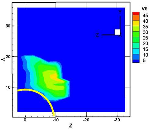
14 a) a) b) b) c) c) d) d) Figure 26. V r distribution for combined jet J3 (45, We 84, q 12), a) x = 5 mm, b) x = 10 mm, c) x = 15 mm, d) x = 20 mm. Figure 27. V θ distribution for combined jet J3 (45, We 84, q 12), a) x = 5 mm, b) x = 10 mm, c) x = 15 mm, d) x = 20 mm.
15 Conclusions We have studied liquid jets injected into a swirling crossflow. The crossflow was non-recirculating, with both axial and tangential velocities decreasing with radius. We studied the jet penetration and observed that the penetration needs to be separated into radial and circumferential penetration to completely describe the jet trajectory. PIV velocity measurements were conducted in cross-sectional as well as streamwise planes, and the velocities were combined to generate a 3-D velocity distribution. Nomenclature d jet diameter m mass flow rate q momentum flux ratio r radial coordinate x streamwise coordinate y vertical coordinate z lateral coordinate R radial axis U crossflow velocity V droplet velocity X streamwise axis Y vertical axis Z lateral axis We aerodynamic weber number φ circumferential displacement θ circumferential coordinate ψ flow angle Θ circumferential axis Subscripts cf crossflow j jet r radial component x streamwise component y vertical component z lateral component θ circumferential (tangential) component References 1. Becker, J., and Hassa, C., Atomization and Sprays 11:49-67 (2002) 2. Chen, T.H., et. al., 31 st Aerospace Sciences Meeting and Exhibit, Reno, NV Birouk, M., Azzopardi, B. J., and Stäbler, T., Particle and Particle Systems Characterization 20: (2003) 4. Lefebvre, A.W., Gas Turbine Combustion, McGraw-Hill, 1983, Ch Tambe, S.B., Liquid Jets in Subsonic Crossflow, MS Thesis, Department of Aerospace Engineering and Engineering Mechanics, University of Cincinnati, Cincinnati OH (2004) 6. Elshamy, O.M., Experimental Investigations of Steady and Dynamic Behavior of Transverse Liquid Jets, PhD Dissertation, Department of Aerospace Engineering and Engineering Mechanics, University of Cincinnati, Cincinnati OH (2007) 7. Becker, J., and Hassa, C., Journal of Engineering for Gas Turbines and Power, 125: Becker, J., Heitz, D., and Hassa, C., Atomization and Sprays, 14:15-35 (2004) 9. Gong et. al., Journal of Propulsion and Power, 22: (2006) 10. Tambe, S.B., Elshamy, O.M., and Jeng, S.-M., 45 th Aerospace Sciences Meeting and Exhibit, Reno, NV Tambe, S.B., Elshamy, O.M., and Jeng, S.-M., 43 rd AIAA/ASME/SAE/ASEE Joint Propulsion Conference and Exhibit, Cincinnati OH Tambe, S.B., 21 st Annual Conference on Liquid Atomization and Spray Systems, Orlando FL Tambe, S.B., Liquid Jets Injected into Non- Uniform Crossflow, PhD Dissertation, Department of Aerospace Engineering, University of Cincinnati, Cincinnati, OH (to be published in 2010)
Experimental Study on the Non-reacting Flowfield of a Low Swirl Burner
 Experimental Study on the Non-reacting Flowfield of a Low Swirl Burner Hang Yin & Ren Dai School of Energy and Powering Engineering, University of Shanghai for Science and Technology Box 25, 516# Jungong
Simulation of a lean direct injection combustor for the next high speed civil transport (HSCT) vehicle combustion systems
 vehicle combustion systems") Center for Turbulence Research Annual Research Briefs 27 241 Simulation of a lean direct injection combustor for the next high speed civil transport (HSCT) vehicle combustion systems By H. El-Asrag, F.
Center for Turbulence Research Annual Research Briefs 27 241 Simulation of a lean direct injection combustor for the next high speed civil transport (HSCT) vehicle combustion systems By H. El-Asrag, F.
THE EFFECT OF SAMPLE SIZE, TURBULENCE INTENSITY AND THE VELOCITY FIELD ON THE EXPERIMENTAL ACCURACY OF ENSEMBLE AVERAGED PIV MEASUREMENTS
 4th International Symposium on Particle Image Velocimetry Göttingen, Germany, September 7-9, 00 PIV 0 Paper 096 THE EFFECT OF SAMPLE SIZE, TURBULECE ITESITY AD THE VELOCITY FIELD O THE EXPERIMETAL ACCURACY
EXPERIMENTAL INVESTIGATION OF AERODYNAMICS AND COMBUSTION PROPERTIES OF A MULTIPLE-SWIRLER ARRAY
 EXPERIMENTAL INVESTIGATION OF AERODYNAMICS AND COMBUSTION PROPERTIES OF A MULTIPLE-SWIRLER ARRAY A dissertation submitted to the Division of Research and Advanced Studies of the University of Cincinnati
Investigation of Radial Swirler Effect on Flow Pattern inside a Gas Turbine Combustor
 Modern Applied Science May, 2009 Investigation of Radial Swirler Effect on Flow Pattern inside a Gas Turbine Combustor Yehia A. Eldrainy Department of Aeronautical Engineering, Faculty of Mechanical Engineering
SIMULTANEOUS VELOCITY AND CONCENTRATION MEASUREMENTS OF A TURBULENT JET MIXING FLOW
 Proceedings of International Symposium on Visualization and Image in Transport Phenomena, Turkey, -9 Oct. SIMULTANEOUS VELOCITY AND CONCENTRATION MEASUREMENTS OF A TURBULENT JET MIXING FLOW Hui HU a, Tetsuo
PARAMETRIC STUDY OF LIQUID FUEL JET IN CROSSFLOW AT CONDITIONS TYPICAL OF AEROSPACE APPLICATIONS
 PARAMETRIC STUDY OF LIQUID FUEL JET IN CROSSFLOW AT CONDITIONS TYPICAL OF AEROSPACE APPLICATIONS A Thesis Presented to The Academic Faculty by Jonathan R. Reichel In Partial Fulfillment of the Requirements
Simultaneous Velocity and Concentration Measurements of a Turbulent Jet Mixing Flow
 Simultaneous Velocity and Concentration Measurements of a Turbulent Jet Mixing Flow HUI HU, a TETSUO SAGA, b TOSHIO KOBAYASHI, b AND NOBUYUKI TANIGUCHI b a Department of Mechanical Engineering, Michigan
4 Mechanics of Fluids (I)
") 1. The x and y components of velocity for a two-dimensional flow are u = 3.0 ft/s and v = 9.0x ft/s where x is in feet. Determine the equation for the streamlines and graph representative streamlines in
1. The x and y components of velocity for a two-dimensional flow are u = 3.0 ft/s and v = 9.0x ft/s where x is in feet. Determine the equation for the streamlines and graph representative streamlines in
ABSTRACT. André Marshall, Associate Professor, Department of Fire Protection Engineering
 ABSTRACT Title of Document: CHARACTERIZATION OF THE INITIAL SPRAY FROM A JET IN CROSSFLOW Yinghui Zheng, Master of Science, 2009 Directed By: André Marshall, Associate Professor, Department of Fire Protection
and Sagar R. Kulkarni 6 Process and Energy Department, Delft University of Technology, Delft, The Netherlands
 Experimental and numerical investigation of spray characteristics in a new FLOX based combustor for liquid fuels for Micro Gas Turbine Range Extender (MGT-REX). James D. Gounder 1, Anton Zizin 2, Oliver
2 Navier-Stokes Equations
 1 Integral analysis 1. Water enters a pipe bend horizontally with a uniform velocity, u 1 = 5 m/s. The pipe is bended at 90 so that the water leaves it vertically downwards. The input diameter d 1 = 0.1
Evolution and transition mechanisms of internal swirling flows with tangential entry
 PHYSICS OF FLUIDS 30, 013601 (2018) Evolution and transition mechanisms of internal swirling flows with tangential entry Yanxing Wang, Xingjian Wang, and Vigor Yang a) School of Aerospace Engineering,
Lecture 9 Laminar Diffusion Flame Configurations
 Lecture 9 Laminar Diffusion Flame Configurations 9.-1 Different Flame Geometries and Single Droplet Burning Solutions for the velocities and the mixture fraction fields for some typical laminar flame configurations.
Fuel Jet in Cross Flow. Experimental Study of Spray Characteristics
 ILASS Americas, 3 rd Annual Conference on Liquid Atomization and Spray Systems, Ventura, CA, May 11 Fuel Jet in Cross Flow. Experimental Study of Spray Characteristics E. Lubarsky, D. Shcherbik, O. Bibik,
NUMERICAL INVESTIGATION ON THE EFFECT OF COOLING WATER SPRAY ON HOT SUPERSONIC JET
 Volume 119 No. 12 2018, 59-63 ISSN: 1314-3395 (on-line version) url: http://www.ijpam.eu ijpam.eu NUMERICAL INVESTIGATION ON THE EFFECT OF COOLING WATER SPRAY ON HOT SUPERSONIC JET Ramprasad T and Jayakumar
DEVELOPMENT OF CFD MODEL FOR A SWIRL STABILIZED SPRAY COMBUSTOR
 DRAFT Proceedings of ASME IMECE: International Mechanical Engineering Conference & Exposition Chicago, Illinois Nov. 5-10, 2006 IMECE2006-14867 DEVELOPMENT OF CFD MODEL FOR A SWIRL STABILIZED SPRAY COMBUSTOR
CHARACTERISTICS OF ELLIPTIC CO-AXIAL JETS
 ELECTRIC POWER 2003 March 4-6, 2003 George R Brown Convention Center, Houston, TX EP 03 Session 07C: Fuels, Combustion and Advanced Cycles - Part II ASME - FACT Division CHARACTERISTICS OF ELLIPTIC CO-AXIAL
Concentration And Velocity Fields Throughout The Flow Field Of Swirling Flows In Gas Turbine Mixers
 University of Central Florida Electronic Theses and Dissertations Doctoral Dissertation (Open Access) Concentration And Velocity Fields Throughout The Flow Field Of Swirling Flows In Gas Turbine Mixers
Experimental Study of Injection of Oil-Water Emulsions into a Crossflow
 ILASS Americas, 24 th Annual Conference on Liquid Atomization and Spray Systems, San Antonio, TX, May 2012 Experimental Study of Injection of Oil-Water Emulsions into a Crossflow C.D. Bolszo, G.A. Gomez
Intensely swirling turbulent pipe flow downstream of an orifice: the influence of an outlet contraction
 13 th Int. Symp. on Appl. Laser Techniques to Fluid Mechanics, Lisbon, Portugal, June 26-29, 26 Intensely swirling turbulent pipe flow downstream of an orifice: the influence of an outlet contraction Marcel
Advances in Fluid Mechanics and Heat & Mass Transfer
 Performance Study of Nozzle Geometry on Heat Transfer Characteristics Part I: Local Heat Transfer M. Attalla Mechanical Power and Energy Department, Faculty of Engineering, South Valley University, Qena
Fluid Dynamics Exercises and questions for the course
 Fluid Dynamics Exercises and questions for the course January 15, 2014 A two dimensional flow field characterised by the following velocity components in polar coordinates is called a free vortex: u r
APPLICATION OF SHADOW DOPPLER VELOCIMETRY TO ARBITRARY-SHAPED DROPLET MEASUREMENT IN WATER SPRAY
 ILASS-Europe 2002 Zaragoza 9 11 September 2002 APPLICATION OF SHADOW DOPPLER VELOCIMETRY TO ARBITRARY-SHAPED DROPLET MEASUREMENT IN WATER SPRAY K. Matsuura*, M. Komaki* and K. Ueyama* kazuaki.matsuura@kanomax.co.jp
Entrained Air around a High Pressure Flat Jet Water Spray
 ILASS Americas, 25 th Annual Conference on Liquid Atomization and Spray Systems, Pittsburgh, PA, May 2013 Entrained Air around a High Pressure Flat Jet Water Spray A.J.Abbas*, G.G.Nasr, M.L.Burby and A.Nourian
Dynamics of Lean Premixed Systems: Measurements for Large Eddy Simulation
 Dynamics of Lean Premixed Systems: Measurements for Large Eddy Simulation D. Galley 1,2, A. Pubill Melsió 2, S. Ducruix 2, F. Lacas 2 and D. Veynante 2 Y. Sommerer 3 and T. Poinsot 3 1 SNECMA Moteurs,
CHAPTER 5 MASS AND ENERGY ANALYSIS OF CONTROL VOLUMES
 Thermodynamics: An Engineering Approach 8th Edition in SI Units Yunus A. Çengel, Michael A. Boles McGraw-Hill, 2015 CHAPTER 5 MASS AND ENERGY ANALYSIS OF CONTROL VOLUMES Lecture slides by Dr. Fawzi Elfghi
NUMERICAL SIMULATION OF LDI COMBUSTOR WITH DISCRETE-JET SWIRLERS USING RE-STRESS MODEL IN THE KIVA CODE
 NUMERICAL SIMULATION OF LDI COMBUSTOR WITH DISCRETE-JET SWIRLERS USING RE-STRESS MODEL IN THE KIVA CODE S. L. Yang, C. Y. Teo, and Y. K. Siow Department of Mechanical Engineering Engineering Mechanics
Laboratory Studies of Fire Whirls (preliminary)
") Laboratory Studies of Fire Whirls (preliminary) Alexander J. Smits, Katie A. Hartl, Stacy Guo and Frederick L. Dryer Princeton University Coupled Atmosphere Bushfire Modelling Workshop 16 18 May 2012 High
Laboratory Studies of Fire Whirls (preliminary) Alexander J. Smits, Katie A. Hartl, Stacy Guo and Frederick L. Dryer Princeton University Coupled Atmosphere Bushfire Modelling Workshop 16 18 May 2012 High
Numerical Study of Laminar Annular Two-Phase Flow in Effervescent Atomizers
 ILASS Americas 28th Annual Conference on Liquid Atomization and Spray Systems, Dearborn, MI, May 2016 Numerical Study of Laminar Annular Two-Phase Flow in Effervescent Atomizers C.K. Mohapatra and M.A.
Comparison between Numerical and Experimental for UVP Measurement in Double Bent Pipe with Out-of-Plane Angle
 Journal of Flow Control, Measurement & Visualization, 24, 2, 54-64 Published Online October 24 in SciRes. http://www.scirp.org/journal/jfcmv http://dx.doi.org/.4236/jfcmv.24.247 Comparison between Numerical
An Essential Requirement in CV Based Industrial Appliances.
 Measurement of Flow P M V Subbarao Professor Mechanical Engineering Department An Essential Requirement in CV Based Industrial Appliances. Mathematics of Flow Rate The Scalar Product of two vectors, namely
Detailed Numerical Simulation of Liquid Jet in Cross Flow Atomization: Impact of Nozzle Geometry and Boundary Condition
 ILASS-Americas 25th Annual Conference on Liquid Atomization and Spray Systems, Pittsburgh, PA, May 23 Detailed Numerical Simulation of Liquid Jet in Cross Flow Atomization: Impact of Nozzle Geometry and
6.1 Momentum Equation for Frictionless Flow: Euler s Equation The equations of motion for frictionless flow, called Euler s
 Chapter 6 INCOMPRESSIBLE INVISCID FLOW All real fluids possess viscosity. However in many flow cases it is reasonable to neglect the effects of viscosity. It is useful to investigate the dynamics of an
A KIVA-based Model for Liquid Jet in Cross Flow
 ILASS-Americas nd Annual Conference on Liquid Atomization and Spray Systems, Cincinnati, OH, May 010 A KIVA-based Model for Liquid Jet in Cross Flow M. Behzad 1, A. Mashayek and N. Ashgriz Multiphase Flow
LOCAL VELOCITY MEASUREMENTS AND COMPUTATIONAL FLUID DYNAMICS (CFD) SIMULATIONS OF SWIRLING FLOW IN A CYLINDRICAL CYCLONE SEPARATOR
 SIMULATIONS OF SWIRLING FLOW IN A CYLINDRICAL CYCLONE SEPARATOR") Proceedings of ETCE 001: Engineering Technology Conference on Energy February 5-7, 001, Houston, Texas ETCE 001-17101 LOCAL VELOCITY MEASUREMENTS AND COMPUTATIONAL FLUID DYNAMICS (CFD) SIMULATIONS OF SWIRLING
Proceedings of ETCE 001: Engineering Technology Conference on Energy February 5-7, 001, Houston, Texas ETCE 001-17101 LOCAL VELOCITY MEASUREMENTS AND COMPUTATIONAL FLUID DYNAMICS (CFD) SIMULATIONS OF SWIRLING
Chapter 4. Experimental Results - Statistics
 Chapter 4 Experimental Results - Statistics 13 4.1 Overview The present chapter includes a presentation and discussion of the results for two major geometries. For the first geometry, the swirler center
Abstract Particle image velocimetry (PIV)
") Computation of Pressure Distribution Using PIV Velocity Data R. Gurka'l), A. Liberzon''), D. Hefet~'~), D. Rubinstein"), U. Shavit(')* 'I) Agricultural Engineering, Technion, Haifa 32000, Israel (anuri@tr.technian.ac.il)
Computation of Pressure Distribution Using PIV Velocity Data R. Gurka'l), A. Liberzon''), D. Hefet~'~), D. Rubinstein"), U. Shavit(')* 'I) Agricultural Engineering, Technion, Haifa 32000, Israel (anuri@tr.technian.ac.il)
SPRAY CHARACTERISTICS OF A KEROSENE JET IN CROSS FLOW OF AIR AT ELEVATED PRESSURE
 Paper I I ILASS08-2- ILASS08-000 ILASS 08 Sep. 8-, 08, Como Lake, Italy SPRAY CHARACTERISTICS OF A KEROSENE JET IN CROSS FLOW OF AIR AT ELEVATE PRESSURE Stefan Freitag, Christoph Hassa German Aerospace
Experiment (4): Flow measurement
: Flow measurement") Experiment (4): Flow measurement Introduction: The flow measuring apparatus is used to familiarize the students with typical methods of flow measurement of an incompressible fluid and, at the same time
Experiment (4): Flow measurement Introduction: The flow measuring apparatus is used to familiarize the students with typical methods of flow measurement of an incompressible fluid and, at the same time
FLOW CHARACTERIZATION WITHIN A SPHERE-PACKED BED USING PIV MEASUREMENT
 FLOW CHARACTERIZATION WITHIN A SPHERE-PACKED BED USING PIV MEASUREMENT J. H.ZHANG, L.XIONG, N.X.WANG and W ZHOU Department of reactor physics, Shanghai institute of applied physics, Chinese academy of
Non-axisymmetric flow field in an axial impulse turbine
 Journal of Mechanical Science and Technology Journal of Mechanical Science and Technology 22 (28) 166~17 www.springerlink.com/content/1738-494x Non-axisymmetric flow field in an axial impulse turbine Byeung
Experimental study on atomization phenomena of kerosene in supersonic cold flow
 Science in China Series E: Technological Sciences 2008 SCIENCE IN CHINA PRESS Springer www.scichina.com tech.scichina.com www.springerlink.com Experimental study on atomization phenomena of kerosene in
EXPERIMENTAL AND NUMERICAL STUDY OF LIQUID JETS IN CROSSFLOW
 EXPERIMENTAL AND NUMERICAL STUDY OF LIQUID JETS IN CROSSFLOW By: Alireza Mashayek A thesis submitted in conformity with the requirements for the degree of Master of Applied Science Graduate Department
SIMULATION OF THE FILM FORMATION AT A HIGH-SPEED ROTARY BELL ATOMIZER USED IN AUTOMOTIVE SPRAY PAINTING PROCESSES
 Paper ID ILASS08-A009 ILASS08-2-14 ILASS 2008 Sep. 8-10, 2008, Como Lake, Italy SIMULATION OF THE FILM FORMATION AT A HIGH-SPEED ROTARY BELL ATOMIZER USED IN AUTOMOTIVE SPRAY PAINTING PROCESSES J. Domnick*,
Figure 1. Schematic of experimental setup.
 June 3 - July 3, Melbourne, Australia 9 9D- STRUCTURE OF 3D OFFSET JETS OVER A SURFACE MOUNTED SQUARE RIB Shawn P. Clark Department of Civil Engineering 7A Chancellors Circle, Winnipeg, Manitoba, R3T V,
Study of injection typology on turbulent homogeneous mixing in a natural gas swirl burner
 Study of injection typology on turbulent homogeneous mixing in a natural gas swirl burner Giulio Solero, Aldo Coghe, Carlo Terragni Dipartimento di Energetica - Politecnico di Milano, Italy Abstract The
INTERNATIONAL JOURNAL OF ADVANCED RESEARCH IN ENGINEERING AND TECHNOLOGY (IJARET)
") INTERNATIONAL JOURNAL OF ADVANCED RESEARCH IN ENGINEERING AND TECHNOLOGY (IJARET) International Journal of Advanced Research in Engineering and Technology (IJARET), ISSN 0976 ISSN 0976-6480 (Print) ISSN
INTERNATIONAL JOURNAL OF ADVANCED RESEARCH IN ENGINEERING AND TECHNOLOGY (IJARET) International Journal of Advanced Research in Engineering and Technology (IJARET), ISSN 0976 ISSN 0976-6480 (Print) ISSN
Mass flow determination in flashing openings
 Int. Jnl. of Multiphysics Volume 3 Number 4 009 40 Mass flow determination in flashing openings Geanette Polanco Universidad Simón Bolívar Arne Holdø Narvik University College George Munday Coventry University
Therefore, the control volume in this case can be treated as a solid body, with a net force or thrust of. bm # V
 When the mass m of the control volume remains nearly constant, the first term of the Eq. 6 8 simply becomes mass times acceleration since 39 CHAPTER 6 d(mv ) CV m dv CV CV (ma ) CV Therefore, the control
Effect of the Liquid Injection Angle on the Atomization of Liquid Jets in Subsonic Crossflows
 , 23rd Annual Conference on Liquid Atomization and Spray Systems, Brno, Czech Republic, September 2010 Effect of the Liquid Injection Angle on the Atomization of Liquid Jets in Subsonic Crossflows H. Almeida,
On Annular Impinging Jets - Experimental Data Analysis
 On Annular Impinging Jets - Experimental Data Analysis Bc. Tomáš Turek Supervisors: Ing. Zdeněk Trávníček, CSc., Prof. Ing. Pavel Šafařík, CSc. Abstract The paper deals with experimental data achieved
Breakup of Round Nonturbulent Liquid Jets in Gaseous Crossflow
 AIAA JOURNAL Vol. 42, No. 12, December 2004 Breakup of Round Nonturbulent Liquid Jets in Gaseous Crossflow K. A. Sallam Oklahoma State University, Stillwater, Oklahoma 74078 and C. Aalburg and G. M. Faeth
PIV measurements of flow structures in a spray dryer
 Downloaded from orbit.dtu.dk on: Nov 19, 218 PIV measurements of flow structures in a spray dryer Meyer, Knud Erik; Velte, Clara Marika; Ullum, Thorvald Published in: Proceedings of PIV'11 Publication
Laminar flow heat transfer studies in a twisted square duct for constant wall heat flux boundary condition
 Sādhanā Vol. 40, Part 2, April 2015, pp. 467 485. c Indian Academy of Sciences Laminar flow heat transfer studies in a twisted square duct for constant wall heat flux boundary condition RAMBIR BHADOURIYA,
THE EFFECT OF TWO PHASE (AIR-WATER) FLOW CHARACTERISTICS ON MOMENTUM FLUX DUE TO FLOW TURNING ELEMENTS AT ATMOSPHERIC CONDITIONS
 FLOW CHARACTERISTICS ON MOMENTUM FLUX DUE TO FLOW TURNING ELEMENTS AT ATMOSPHERIC CONDITIONS") International Journal of Latest Trends in Engineering and Technology Vol.(8)Issue(1), pp.319-328 DOI: http://dx.doi.org/10.21172/1.81.041 e-issn:2278-621x AN EXPERIMENTAL STUDY OF THE EFFECT OF TWO PHASE
International Journal of Latest Trends in Engineering and Technology Vol.(8)Issue(1), pp.319-328 DOI: http://dx.doi.org/10.21172/1.81.041 e-issn:2278-621x AN EXPERIMENTAL STUDY OF THE EFFECT OF TWO PHASE
The online of midterm-tests of Fluid Mechanics 1
 The online of midterm-tests of Fluid Mechanics 1 1) The information on a can of pop indicates that the can contains 460 ml. The mass of a full can of pop is 3.75 lbm while an empty can weights 80.5 lbf.
SIMULATION OF PRECESSION IN AXISYMMETRIC SUDDEN EXPANSION FLOWS
 Second International Conference on CFD in the Minerals and Process Industries CSIRO, Melbourne, Australia 6-8 December 1999 SIMULATION OF PRECESSION IN AXISYMMETRIC SUDDEN EXPANSION FLOWS Baoyu GUO, Tim
PASSIVE CONTROL ON JET MIXING FLOWS BY USING VORTEX GENERATORS
 Proceedings of the Sixth Triennial International Symposium on Fluid Control, Measurement and Visualization, Sherbrooke, Canada, August -7,. PASSIVE CONTROL ON JET MIXING FLOWS BY USING VORTEX GENERATORS
(Refer Slide Time: 4:41)
") Fluid Machines. Professor Sankar Kumar Som. Department Of Mechanical Engineering. Indian Institute Of Technology Kharagpur. Lecture-30. Basic Principle and Energy Transfer in Centrifugal Compressor Part
Fluid Machines. Professor Sankar Kumar Som. Department Of Mechanical Engineering. Indian Institute Of Technology Kharagpur. Lecture-30. Basic Principle and Energy Transfer in Centrifugal Compressor Part
Effects of the Leakage Flow Tangential Velocity in Shrouded Axial Compressor Cascades *
 TSINGHUA SCIENCE AND TECHNOLOGY ISSNll1007-0214ll21/21llpp105-110 Volume 14, Number S2, December 2009 Effects of the Leakage Flow Tangential Velocity in Shrouded Axial Compressor Cascades * KIM Jinwook
Shadow Doppler velocimetry with double fiber-array sensors
 Shadow Doppler velocimetry with double fiber-array sensors by K. Matsuura (1), M. Komaki (2) and K. Ueyama (3) KANOMAX Research Institute Co., Ltd. 2-1, Shimizu, Suita, Osaka 565-0805; Japan (1) E-Mail:
Keywords - Gas Turbine, Exhaust Diffuser, Annular Diffuser, CFD, Numerical Simulations.
 Numerical Investigations of PGT10 Gas Turbine Exhaust Diffuser Using Hexahedral Dominant Grid Vaddin Chetan, D V Satish, Dr. Prakash S Kulkarni Department of Mechanical Engineering, VVCE, Mysore, Department
We are IntechOpen, the world s leading publisher of Open Access books Built by scientists, for scientists. International authors and editors
 We are IntechOpen, the world s leading publisher of Open Access books Built by scientists, for scientists 4, 116, 12M Open access books available International authors and editors Downloads Our authors
Lect 22. Radial Flow Turbines. Prof. Bhaskar Roy, Prof. A M Pradeep, Department of Aerospace, IIT Bombay
 Lecture Lect Radial Flow Turbines Lect Radial inflow turbines, which look similar to centrifugal compressor, are considered suitable for application in small aircraft engines. In many applications a radial
White Paper FINAL REPORT AN EVALUATION OF THE HYDRODYNAMICS MECHANISMS WHICH DRIVE THE PERFORMANCE OF THE WESTFALL STATIC MIXER.
 White Paper FINAL REPORT AN EVALUATION OF THE HYDRODYNAMICS MECHANISMS WHICH DRIVE THE PERFORMANCE OF THE WESTFALL STATIC MIXER Prepared by: Dr. Thomas J. Gieseke NUWCDIVNPT - Code 8233 March 29, 1999
One-dimensional Spray Combustion Optimization with a Sequential Linear Quadratic Algorithm
 One-dimensional Spray Combustion Optimization with a Sequential Linear Quadratic Algorithm Justin A. Sirignano, Luis Rodriguez, Athanasios Sideris, and William A. Sirignano Department of Mechanical and
Modelling Nozzle throat as Rocket exhaust
 Vol. 3, Issue. 4, Jul - Aug. 2013 pp-2502-2506 ISSN: 2249-6645 Modelling Nozzle throat as Rocket exhaust Keshava Rao P. 1, Komma Rahul 2, Souda Dinesh 3 1 (Mechanical Engineering, CBIT College, India)
CLASS Fourth Units (Second part)
") CLASS Fourth Units (Second part) Energy analysis of closed systems Copyright The McGraw-Hill Companies, Inc. Permission required for reproduction or display. MOVING BOUNDARY WORK Moving boundary work (P
CLASS Fourth Units (Second part) Energy analysis of closed systems Copyright The McGraw-Hill Companies, Inc. Permission required for reproduction or display. MOVING BOUNDARY WORK Moving boundary work (P
2.2 The Turbulent Round Jet
 Canonical Turbulent Flows 13. The Turbulent Round Jet Jet flows are a subset of the general class of flows known as free shear flows where free indicates that the shear arises in the absence of a boundary
NUMERICAL PREDICTIONS AND EXPERIMENTS ON SUPERSONIC JET MIXING FROM CASTELLATED NOZZLES
 ICAS CONGRESS NUMERICAL PREDICTIONS AND EXPERIMENTS ON SUPERSONIC JET MIXING FROM CASTELLATED NOZZLES A. J. Saddington, N. J. Lawson, K. Knowles Aeromechanical Systems Group Department of Aerospace, Power
DETERMINATION OF ABRASIVE PARTICLE VELOCITY USING LASER-INDUCED FLUORESCENCE AND PARTICLE TRACKING METHODS IN ABRASIVE WATER JETS
 2005 WJTA American Waterjet Conference August 21-23, 2005 Houston, Texas DETERMINATION OF ABRASIVE PARTICLE VELOCITY USING LASER-INDUCED FLUORESCENCE AND PARTICLE TRACKING METHODS IN ABRASIVE WATER JETS
COURSE NUMBER: ME 321 Fluid Mechanics I 3 credit hour. Basic Equations in fluid Dynamics
 COURSE NUMBER: ME 321 Fluid Mechanics I 3 credit hour Basic Equations in fluid Dynamics Course teacher Dr. M. Mahbubur Razzaque Professor Department of Mechanical Engineering BUET 1 Description of Fluid
FLOW-FIELD OF A 12-LOBE CONVOLUTED MIXER
 24 TH INTERNATIONAL CONGRESS OF THE AERONAUTICAL SCIENCES FLOW-FIELD OF A 12-LOBE CONVOLUTED MIXER Leiyong Jiang, Ibrahim Yimer and W.E. Carscallen Gas Turbine Environmental Research Centre Institute for
William A. Sirignano Mechanical and Aerospace Engineering University of California, Irvine
 Combustion Instability: Liquid-Propellant Rockets and Liquid-Fueled Ramjets William A. Sirignano Mechanical and Aerospace Engineering University of California, Irvine Linear Theory Nonlinear Theory Nozzle
COMPUTATIONAL METHOD
 Multi Objective Design Optimization of Rocket Engine Turbopump Turbine Naoki Tani, Akira Oyama and Nobuhiro Yamanishi tani.naoki@jaxa.jp Japan Aerospace Exploration Agency JAXA is now planning to develop
Isaac Boxx 1*, Campbell Carter 2, Michael Stöhr 1, Wolfgang Meier 1
 Experimental Study of Auto-Ignition Phenomena in Swirl-Stabilized LPP Flames in Gas Turbine Model Combustors using khz Framerate OH-PLIF and Stereo-PIV Isaac Boxx 1*, Campbell Carter 2, Michael Stöhr 1,
Contents. Preface... xvii
 Contents Preface... xvii CHAPTER 1 Idealized Flow Machines...1 1.1 Conservation Equations... 1 1.1.1 Conservation of mass... 2 1.1.2 Conservation of momentum... 3 1.1.3 Conservation of energy... 3 1.2
Experimental Investigation of the Velocity Distribution near the Swirl Generator of a Uniflow Cyclone for Performance Data Prediction
 Experimental Investigation of the Velocity Distribution near the Swirl Generator of a Uniflow Cyclone for Performance Data Prediction M. Pillei 1,2,*, R. Goller 1, T. Kofler 1, A. Wierschem 2, M. Kraxner
CFD ANALYSIS OF TURBULENCE EFFECT ON REACTION IN STIRRED TANK REACTORS
 CFD ANALYSIS OF TURBULENCE EFFECT ON REACTION IN STIRRED TANK REACTORS Udaya Bhaskar Reddy R*, Gopalakrishnan S, Ramasamy E Department of Chemical Engineering, Coimbatore Institute of Technology, Coimbatore-
Lecture 2 Flow classifications and continuity
 Lecture 2 Flow classifications and continuity Dr Tim Gough: t.gough@bradford.ac.uk General information 1 No tutorial week 3 3 rd October 2013 this Thursday. Attempt tutorial based on examples from today
CHAPTER 3 BASIC EQUATIONS IN FLUID MECHANICS NOOR ALIZA AHMAD
 CHAPTER 3 BASIC EQUATIONS IN FLUID MECHANICS 1 INTRODUCTION Flow often referred as an ideal fluid. We presume that such a fluid has no viscosity. However, this is an idealized situation that does not exist.
PIV INVESTIGATION OF THE INTERNAL FLOW STRUCTURE IN A CENTRIFUGAL PUMP IMPELLER
 PIV INVESTIGATION OF THE INTERNAL FLOW STRUCTURE IN A CENTRIFUGAL PUMP IMPELLER N. Pedersen (np@et.dtu.dk) 1 and C.B. Jacobsen 2 1 Dept. of Energy Engineering, Fluid Mechanics Section Building 43, Technical
mywbut.com Hydraulic Turbines
 Hydraulic Turbines Hydro-electric power accounts for up to 0% of the world s electrical generation. Hydraulic turbines come in a variety of shapes determined by the available head and a number of sizes
FLAME AND FLOW DYNAMICS OF A SELF-EXCITED, STANDING WAVE CIRCUMFERENTIAL INSTABILITY IN A MODEL ANNULAR GAS TURBINE COMBUSTOR
 Proceedings of the ASME Turbo Expo 2013, Power for Land, Sea, and Air GT2013 June 3-7, 2013, San Antonio, Texas GT2013-95897 FLAME AND FLOW DYNAMICS OF A SELF-EXCITED, STANDING WAVE CIRCUMFERENTIAL INSTABILITY
2 Internal Fluid Flow
 Internal Fluid Flow.1 Definitions Fluid Dynamics The study of fluids in motion. Static Pressure The pressure at a given point exerted by the static head of the fluid present directly above that point.
ON THE ONSET AND DEVELOPMENT OF ROTATING STALL WITHIN A VANED DIFFUSER OF A CENTRIFUGAL PUMP
 Proceedings of FEDSM` ASME/JSME Fluids Engineering Division Summer Meeting June -,, Boston FEDSM - ON THE ONSET AND DEVELOPMENT OF ROTATING STALL WITHIN A VANED DIFFUSER OF A CENTRIFUGAL PUMP Manish SINHA,
FLOW MEASUREMENT. INC 102 Fundamental of Instrumentation and Process Control 2/2560
 FLOW MEASUREMENT INC 102 Fundamental of Instrumentation and Process Control 2/2560 TABLE OF CONTENTS A. INTRODUCTION B. LOCAL FLOW MEASUREMENT B.1 Particle Image Velocimetry (PIV) B.2 Laser doppler anemometry
Advanced Structural Analysis EGF Cylinders Under Pressure
 Advanced Structural Analysis EGF316 4. Cylinders Under Pressure 4.1 Introduction When a cylinder is subjected to pressure, three mutually perpendicular principal stresses will be set up within the walls
Optical diagnostic techniques for spray systems
 Optical diagnostic techniques for spray systems V. Stetsyuk and C. Crua Centre for Automotive Engineering, University of Brighton Workshop: Utilisation and valorisation of CO 2 for green chemistry Chemical
INTERNAL FLOW IN A Y-JET ATOMISER ---NUMERICAL MODELLING---
 ILASS-Europe 2002 Zaragoza 9 11 September 2002 INTERNAL FLOW IN A Y-JET ATOMISER ---NUMERICAL MODELLING--- Z. Tapia, A. Chávez e-mail: ztapia@imp.mx Instituto Mexicano del Petróleo Blvd. Adolfo Ruiz Cortines
Documentation of the Solutions to the SFPE Heat Transfer Verification Cases
 Documentation of the Solutions to the SFPE Heat Transfer Verification Cases Prepared by a Task Group of the SFPE Standards Making Committee on Predicting the Thermal Performance of Fire Resistive Assemblies
m SThe Society shall not be responsible for statements or opinions advanced in papers or discussion at meetings of the Society or of its Divisions or
 THE AMERICAN SOCIETY OF MECHANICAL ENGINEERS 345 E. 47th St., New York, N.Y. 10017 98-GT-260 m SThe Society shall not be responsible for statements or opinions advanced in papers or discussion at meetings
A. Aleksandrov, H. Bockhorn
 Experimental Investigation of the impact of imposed air inlet velocity oscillations on Soot Formation and Oxidation using an advanced 2-Colour-TIRE-LII A. Aleksandrov, H. Bockhorn Engler-Bunte-Institute,
PhysicsAndMathsTutor.com 1
 PhysicsAndMathsTutor.com 1 Q1. A grinding wheel is used to sharpen chisels in a school workshop. A chisel is forced against the edge of the grinding wheel so that the tangential force on the wheel is a
Effect of Primary Spray Characteristics on the Spray Generated by an Airblast Atomizer under High-Pressure Conditions
 ISS mericas, st nnual Conference on iquid tomization and Spray Systems, Orlando, Florida, May 8-8 Effect of Primary Spray Characteristics on the Spray Generated by an irblast tomizer under High-Pressure
Engineering Mechanics Department of Mechanical Engineering Dr. G. Saravana Kumar Indian Institute of Technology, Guwahati
 Engineering Mechanics Department of Mechanical Engineering Dr. G. Saravana Kumar Indian Institute of Technology, Guwahati Module 3 Lecture 6 Internal Forces Today, we will see analysis of structures part
Heat Transfer Analysis of Machine Tool Main Spindle
 Technical Paper Heat Transfer Analysis of Machine Tool Main Spindle oshimitsu HIRASAWA Yukimitsu YAMAMOTO CAE analysis is very useful for shortening development time and reducing the need for development
Experimental and Numerical Investigation of Two- Phase Flow through Enlarging Singularity
 Purdue University Purdue e-pubs International Refrigeration and Air Conditioning Conference School of Mechanical Engineering 212 Experimental and Numerical Investigation of Two- Phase Flow through Enlarging
EFFECT OF VELOCITY RATIO ON FLOW AND HEAT TRANSFER CHARACTERISTICS OF AN IMPINGING JET IN CROSSFLOW
 The th PSU-UNS International Conference on Engineering and 78 Technology (ICET-), Phuket, May -, Prince of Songkla University, Faculty of Engineering Hat Yai, Songkhla, Thailand 9 EFFECT OF VELOCITY RATIO