Interaction Diagram Dumbbell Concrete Shear Wall Unsymmetrical Boundary Elements
|
|
|
- Clifton Barber
- 5 years ago
- Views:
Transcription


1 Interaction Diagram Dumbbell Concrete Shear Wall Unsymmetrical Boundary Elements
2
3 Interaction Diagram - Dumbbell Concrete Shear Wall Unsymmetrical Boundary Elements Investigate the capacity for the irregular T-shaped concrete shear wall acting as a retaining wall for a deep underground parking garage facility in a mixed use multistory building. The T-shaped formation comprises the basement retaining wall (Tee flange), the stem serving as the shear wall (Tee web) and, the first building column of the standard 30 x 30 bays (Tee bottom). Develop a P-M diagram by determining seven control points on the interaction diagram and compare the calculated values with exact values from the complete interaction diagram generated by spcolumn engineering software program from StructurePoint. The initial reinforcement bar size and arrangement in the shear wall were obtained assuming a light reinforcement ratio of 0.60% with a final as-designed reinforcement ratio of 2.2%. Figure 1 Reinforced Concrete Shear Wall Cross-Section Version: January
4 Contents Control Points (Moment Rotation about the Negative Y-Axis) Maximum Compression Nominal axial compressive strength Factored axial compressive strength Maximum (allowable) factored axial compressive strength Bar Stress Near Tension Face Equal to Zero, ( ε s = f s = 0 ) c, a, and strains in the reinforcement Forces in the concrete and steel ϕp n and ϕm n Bar Stress Near Tension Face Equal to 0.5 f y, ( f s = f y ) c, a, and strains in the reinforcement Forces in the concrete and steel ϕp n and ϕm n Bar Stress Near Tension Face Equal to f y, ( f s = - f y ) c, a, and strains in the reinforcement Forces in the concrete and steel ϕp n and ϕm n Bar Strain Near Tension Face Equal to in./in., ( ε s = in./in.) c, a, and strains in the reinforcement Forces in the concrete and steel ϕp n and ϕm n Pure Bending c, a, and strains in the reinforcement Forces in the concrete and steel ϕp n and ϕm n Maximum Tension P nt and ϕp nt M n and ϕm n Control Points (Moment Rotation about the Positive Y-Axis) Column Interaction Diagram - spcolumn Software Summary and Comparison of Design Results Conclusions & Observations Version: January
5 Code Building Code Requirements for Structural Concrete (ACI ) and Commentary (ACI 318R-14) Reference spcolumn Engineering Software Program Manual v5.50, STRUCTUREPOINT, 2016 Interaction Diagram - Tied Reinforced Concrete Column (ACI ) Example, STRUCTUREPOINT, 2017 Design Data f c = 4000 psi f y = 60,000 psi Clear Cover = 2 in. The reinforcement size and location selected for this shear wall are shown in Figure 1. Detailed bar and concrete shape data are tabulated below. 1
6 Table 1 - Reinforcement Data Table 2 - Concrete Shape Data Layer A s/bar, in 2 # of bars d, in Part h, in b, in A c/part, in A c(total), in Note: Layer 1 and 2 are in the retaining wall section (Tee flange) Layer 33, 34, and 35 are in the building column section (Tee bottom) The rest of the layers are in the shear wall section 2
7 Solution Use the traditional detailed approach to generate the interaction diagram for the concrete wall section shown above by determining the following seven control points for positive and negative moment about the y-axis: Point 1: Maximum compression Point 2: Bar stress near tension face equal to zero, ( f s = 0 ) Point 3: Bar stress near tension face equal to 0.5 f y ( f s = f y ) Point 4: Bar stress near tension face equal to f y ( f s = - f y ) Point 5: Bar strain near tension face equal to Point 6: Pure bending Point 7: Maximum tension Several terms are used to facilitate the following calculations: A g = gross area of concrete section, in 2. x P o = geometric centroid location along the x-axis, in. = nominal axial compressive strength, kip P o M o = factored axial compressive strength, kip = moment strength associated with the factored axial compressive strength, kip-ft P n, max = maximum (allowable) factored axial compressive strength, kip c a = distance from the fiber of maximum compressive strain to the neutral axis, in. = depth of equivalent rectangular stress block, in. A p = gross area of equivalent rectangular stress block, in 2. x p = plastic centroid location along the x-axis, in. C c ε s,i C s,i T s,i = compression force in equivalent rectangular stress block, kip = strain value in reinforcement layer i, in./in. = compression force in reinforcement layer i, kip = tension force in reinforcement layer i, kip 3
8 A complete nominal and design interaction (P-M) diagrams are shown in Figure 2 along with the key control points. The observations on the P-M diagram of an irregular wall or column sections are summarized as follows: 1. The interaction diagram for an irregular section is tilted provided that the moments are taken about the geometric centroid. This is due to the unsymmetrical geometry and/or reinforcement configuration. 2. The calculation of an interaction diagram for an irregular section follows the same procedure as a regular section, except at uniform compressive and uniform tensile strains (i.e., points for compression and points for tension). In these cases, the moment values become non zero, unlike the symmetrical sections, due to unsymmetrical reinforcement configuration causing a moment of steel forces about the centroid. 3. The left side of the P-M diagram shows elevated axial load capacities for all control points owing to the increased area of the concrete compression block mainly because the large wall flange is in compression including a larger reinforcement area in the flange. 4. In large cross sections with irregular geometries and/or reinforcement configurations, very high strains may be reached in the reinforcement near the tension face. This condition will be prominent in the range between pure bending control point and maximum tension control point (the strain value at maximum tension point is assumed as infinity). This may be exacerbated by low reinforcement amounts further lowering neutral axis depth which in turn results in a further increase in tensile strains at reinforcement. In such cases, engineers may review the amount of steel and revise as required to achieve what they deem reasonable to balance the steel ratio with the steel strain in tension as will be seen in this example. 4
9 Figure 2 Irregular Section Interaction Diagram Control Points 5
10 Control Points (Moment Rotation about the Negative Y-Axis) Begin the calculation for the moment capacity where the flange of the T-shaped cross-section is in compression and the column at the bottom of the stem is in tension. 1. Maximum Compression 1.1. Nominal axial compressive strength From Tables 1 and 2: Calculate total gross cross-sectional area: Ag b1 h1 b2 h2 b3 h ,576 in. 2 Calculate the center of gravity (geometrical centroid): 2 b1 h1 / 2 b2 h2 h1 h2 / 2 b3 h3 h1 h2 h3 / 2 x b h b h b h x / / / in. A in. st 2 P 0.85 f ' ( A A ) f A ACI ( ) o c g st y st P , ,242 kips o Since the section is irregular (not symmetrical) about the y-axis, the moment capacity associated with the maximum axial compressive strength is not equal to zero. As commonly is the case in symmetrical shapes with symmetrical reinforcing arrangements. C f A ACI ( ) ' c 0.85 c g , 000 7,576 25, 758 kip The area of the reinforcement has been included in the area (A g) used to compute C c. As a result, it is necessary to subtract 0.85f c from f s before computing C si for each reinforcement layer (i): ' ' Csi fsi 0.85 fc Asi Where i indicates the reinforcement layer number as shown in the following Table. The concrete compression force is located at the centroid of the section making the location of the geometric centroid coincide with the plastic centroid (x = x p). Thus, the moment capacity is developed by the reinforcement only since the bars forces are not at the geometric centroid. The following Table shows the calculation of the moment capacity associated with the maximum axial compressive strength. 6
11 35, M C x x C x d 4, 008 kip-ft o c unc s i i i1 Table 3 - Moment Capacity for the First Control Point Layer A s/bar, in 2 # of bars d, in C s, kip M sc, kip-ft , , , , ,630 M o = M sc, kip-ft -4,008 7
12 1.2. Factored axial compressive strength 0.65 ACI (Table ) , ,357 kips P o M o M 0.654, 008 2, 605 kip-ft o 1.3. Maximum (allowable) factored axial compressive strength P, 0.80 P ,357 14, 686 kips ACI (Table ) n max o 8
13 2. Bar Stress Near Tension Face Equal to Zero, ( εs = fs = 0 ) Figure 3 Strains, Forces, and Moment Arms (ε t = f s = 0) 9
14 Strain ε s is zero in the extreme layer of tension steel. This case is considered when calculating an interaction diagram because it marks the change from compression lap splices being allowed on all longitudinal bars, to the more severe requirement of tensile lap splices. ACI ( and 2) The following shows the general procedure to calculate the axial and moment capacities of the irregular wall section at this control point, all the calculated values are shown in the next Table c, a, and strains in the reinforcement cd in. Where c is the distance from the fiber of maximum compressive strain to the neutral axis. ACI ( ) a 1 c in. ACI ( ) Where: a = Depth of equivalent rectangular stress block ' f c ACI (Table ) s, ACI (Table ) ACI ( ) cu di s, i cu ( 1) c Fy 60 y E 29, 000 s 2.2. Forces in the concrete and steel Since a = in. > h 1 = 14 in., the area and centroid of the concrete equivalent block (see the previous Figure) can be found as follows: 2 A , 470 in. x p p x p 2 b1 h1 / 2 b2 a h1 h1 a h1 / 2 b h b a h / / in. 10
15 C f A ACI ( ) ' c 0.85 c p , 000 6, , 000 kip (compression) if s, i y reinforcement has yielded fs, i fy s, i < y reinforcement has not yielded fs, i s, i Es If the reinforcement layer is located within the depth of the equivalent rectangular stress block (a), it is necessary to subtract 0.85f c from f s,i before computing F s,i since the area of the reinforcement in this layer has been included in the area used to compute C c. d a F f 0.85 f A if d i a Fs, i fs, i As, i ' i s, i s, i c s, i The force developed in the reinforcement layer (F s,i) is considered as compression force (C s,i) if the effective depth of this steel layer (d i) is less than c (the distance from the fiber of maximum compressive strain to the neutral axis), otherwise it is considered as tension force (T s,i) ϕp n and ϕm n Using values from the next Table: P C C T 23,787 kip n c s, i s, i i1 i , , 461kip P n 35 35,, M C x x C x d T d x 80, 276 kip-ft n c unc s i i s i i i1 i , ,179kip-ft M n 11
16 Table 4 - Axial and Moment Capacity for the Second Control Point Layer A s/bar, in 2 # of bars d, in ε s, in./in. f s,i, ksi C s,i, kip T s,i, kip M n,i, kip-ft Concrete --- x p = , ,000 P n, kip -23,787 M n, kip-ft -80,276 12
17 3. Bar Stress Near Tension Face Equal to 0.5 fy, ( fs = fy ) Figure 4 Strains, Forces, and Moment Arms (f s = f y 13
18 The following show the general procedure to calculate the axial and moment capacities of the irregular wall section at this control point, all the calculated values are shown in the next Table c, a, and strains in the reinforcement f y 60 y E 29, 000 s s,35 y y tension reinforcement has not yielded cu ACI (Table ) ACI ( ) c d cu s,35 cu in. Where c is the distance from the fiber of maximum compressive strain to the neutral axis. ACI ( ) a 1 c in. ACI ( ) Where: a = Depth of equivalent rectangular stress block ' f c ACI (Table ) di s, i cu ( 1) c 3.2. Forces in the concrete and steel Since a = in. > h 1 = 14 in., the area and centroid of the concrete equivalent block (see the previous Figure) can be found as follows: 2 A , 264 in. x p p x p 2 b1 h1 / 2 b2 a h1 h1 a h1 / 2 b h b a h / / in. C f A ACI ( ) ' c 0.85 c p , 000 5, ,896 kip (compression) 14
19 if s, i y reinforcement has yielded fs, i fy s, i < y reinforcement has not yielded fs, i s, i Es If the reinforcement layer is located within the depth of the equivalent rectangular stress block (a), it is necessary to subtract 0.85f c from f s,i before computing F s,i since the area of the reinforcement in this layer has been included in the area used to compute C c. d a F f 0.85 f A if d i a Fs, i fs, i As, i ' i s, i s, i c s, i The force developed in the reinforcement layer (F s,i) is considered as compression force (C s,i) if the effective depth of this steel layer (d i) is less than c (the distance from the fiber of maximum compressive strain to the neutral axis), otherwise it is considered as tension force (T s,i) ϕp n and ϕm n Using values from the next Table: P C C T 19,261 kip n c s, i s, i i1 i , ,520kip P n 35 35,, M C x x C x d T d x 131, 306 kip-ft n c unc s i i s i i i1 i ,306 85,349kip-ft M n 15
20 Table 5 - Axial and Moment Capacity for the Third Control Point Layer A s/bar, in 2 # of bars d, in ε s, in./in. f s,i, ksi C s,i, kip T s,i, kip M n,i, kip-ft , , , ,394.0 Concrete --- x p = , ,506 P n, kip -19,261 M n, kip-ft -131,300 16
21 4. Bar Stress Near Tension Face Equal to fy, ( fs = - fy ) Figure 5 Strains, Forces, and Moment Arms (f s = - f y) 17
22 This strain distribution is called the balanced failure case and the compression-controlled strain limit. It marks the change from compression failures originating by crushing of the compression surface of the section, to tension failures initiated by yield of longitudinal reinforcement. It also marks the start of the transition zone for ϕ for columns and walls in which ϕ increases from 0.65 (or 0.75 for spiral columns) up to The following show the general procedure to calculate the axial and moment capacities of the irregular wall section at this control point, all the calculated values are shown in the next Table c, a, and strains in the reinforcement f y 60 y E 29, 000 s s, tension reinforcement has yielded y 0.65 cu ACI (Table ) ACI ( ) c d cu s,35 cu in. Where c is the distance from the fiber of maximum compressive strain to the neutral axis. ACI ( ) a 1 c in. ACI ( ) Where: ' f c ACI (Table ) di s, i cu ( 1) c 4.2. Forces in the concrete and steel Since a = 199 in. > h 1 = 14 in., the area and centroid of the concrete equivalent block (see the previous Figure) can be found as follows: 2 A ,550 in. x p p 2 b1 h1 / 2 b2 a h1 h1 a h1 / 2 b h b a h
23 x p / / in. C f A ACI ( ) ' c 0.85 c p , 000 4,550 15, 468 kip (compression) if s, i y reinforcement has yielded fs, i fy s, i < y reinforcement has not yielded fs, i s, i Es If the reinforcement layer is located within the depth of the equivalent rectangular stress block (a), it is necessary to subtract 0.85f c from f s,i before computing F s,i since the area of the reinforcement in this layer has been included in the area used to compute C c. d a F f 0.85 f A if d i a Fs, i fs, i As, i ' i s, i s, i c s, i The force developed in the reinforcement layer (F s,i) is considered as compression force (C s,i) if the effective depth of this steel layer (d i) is less than c (the distance from the fiber of maximum compressive strain to the neutral axis), otherwise it is considered as tension force (T s,i) ϕp n and ϕm n Using values from the next Table: P C C T 16,397 kip n c s, i s, i i1 i ,397 10, 658kip P n 35 35,, M C x x C x d T d x 149,884 kip-ft n c unc s i i s i i i1 i ,884 97, 424kip-ft M n 19
24 Table 6 - Axial and Moment Capacity for the Fourth Control Point Layer A s/bar, in 2 # of bars d, in ε s, in./in. f s,i, ksi C s,i, kip T s,i, kip M n,i, kip-ft Concrete --- x p = , ,516.1 P n, kip -16,397 M n, kip-ft -149,886 20
25 5. Bar Strain Near Tension Face Equal to in./in., ( εs = in./in.) Figure 6 Strains, Forces, and Moment Arms (ε s = in./in.) 21
26 This corresponds to the tension-controlled strain limit of It is the strain at the tensile limit of the transition zone for ϕ, used to define a tension-controlled section. The following show the general procedure to calculate the axial and moment capacities of the irregular wall section at this control point, all the calculated values are shown in the next Table c, a, and strains in the reinforcement f y 60 y E 29, 000 s s, tension reinforcement has yielded y 0.9 ACI (Table ) cu ACI ( ) c d cu s,35 cu in. Where c is the distance from the fiber of maximum compressive strain to the neutral axis. ACI ( ) a 1 c in. ACI ( ) Where: ' f c ACI (Table ) di s, i cu ( 1) c 5.2. Forces in the concrete and steel Since a = in. > h 1 = 14 in., the area and centroid of the concrete equivalent block (see the previous Figure) can be found as follows: 2 A ,529 in. x p p x p 2 b1 h1 / 2 b2 a h1 h1 a h1 / 2 b h b a h / / in. C f A ACI ( ) ' c 0.85 c p , 000 3,529 11,998 kip (compression) 22
27 if s, i y reinforcement has yielded fs, i fy s, i < y reinforcement has not yielded fs, i s, i Es If the reinforcement layer is located within the depth of the equivalent rectangular stress block (a), it is necessary to subtract 0.85f c from f s,i before computing F s,i since the area of the reinforcement in this layer has been included in the area used to compute C c. d a F f 0.85 f A if d i a Fs, i fs, i As, i ' i s, i s, i c s, i The force developed in the reinforcement layer (F s,i) is considered as compression force (C s,i) if the effective depth of this steel layer (d i) is less than c (the distance from the fiber of maximum compressive strain to the neutral axis), otherwise it is considered as tension force (T s,i) ϕp n and ϕm n Using values from the next Table: P C C T 12,390 kip n c s, i s, i i1 i ,390 11,151kip P n 35 35,, M C x x C x d T d x 153, 593 kip-ft n c unc s i i s i i i1 i , , 234kip-ft M n 23
28 Table 7 - Axial and Moment Capacity for the Fifth Control Point Layer A s/bar, in 2 # of bars d, in ε s, in./in. f s,i, ksi C s,i, kip T s,i, kip M n,i, kip-ft Concrete --- x p = , ,178.1 P n, kip -12,390 M n, kip-ft -153,595 24
29 6. Pure Bending This corresponds to the case where the nominal axial load capacity, P n, is equal to zero. The following show the general iterative procedure to calculate the moment capacity of the irregular wall section at this control point, all the calculated values are shown in the next Table c, a, and strains in the reinforcement Try c 4.32 in. Where c is the distance from the fiber of maximum compressive strain to the neutral axis. ACI ( ) a 1 c in. ACI ( ) Where: ' f c ACI (Table ) ACI ( ) cu f y 60 y E 29, 000 s s,35 d c (Tension) > y tension reinforcement has yielded 0.9 ACI (Table ) di s, i cu ( 1) c The maximum tensile strain calculated above is significantly higher than the yield strain and indicates the section is very lightly reinforced. Increasing the steel area will result in lower maximum strain and increase the moment capacity Forces in the concrete and steel Since a = 3.67 in. < h 1 = 14 in., the area and centroid of the concrete equivalent block can be found as follows: A in. p 2 a 3.67 xp 1.84 in. 2 2 C f A ACI ( ) ' c 0.85 c unc , , 748 kip (compression) 25
30 if s, i y reinforcement has yielded fs, i fy s, i < y reinforcement has not yielded fs, i s, i Es If the reinforcement layer is located within the depth of the equivalent rectangular stress block (a), it is necessary to subtract 0.85f c from f s,i before computing F s,i since the area of the reinforcement in this layer has been included in the area used to compute C c. d a F f 0.85 f A if d i a Fs, i fs, i As, i ' i s, i s, i c s, i The force developed in the reinforcement layer (F s,i) is considered as compression force (C s,i) if the effective depth of this steel layer (d i) is less than c (the distance from the fiber of maximum compressive strain to the neutral axis), otherwise it is considered as tension force (T s,i) ϕp n and ϕm n Using values from the next Table: P C C T n c s, i s, i i1 i1 0 kip The assumption that c = 4.32 in. is correct 35 35,, M C x x C x d T d x 30, 440 kip-ft n c unc s i i s i i i1 i , ,396kip-ft M n 26
31 Table 8 - Axial and Moment Capacity for the Sixth Control Point Layer A s/bar, in 2 # of bars d, in ε s, in./in. f s,i, ksi C s,i, kip T s,i, kip M n,i, kip-ft , , , , ,788.1 Concrete --- x p = , ,070.5 P n, kip 0.0 M n, kip-ft -30,440 27
32 7. Maximum Tension The final loading case to be considered is concentric axial tension. The strength under maximum axial tension is computed by assuming that the section is completely cracked through and subjected to a uniform strain greater than or equal to the yield strain in tension. The axial tensile strength under such a loading is equal to the yield strength of the reinforcement in tension P nt and ϕp nt Pnt f y Ast 60, , 633 kip ACI ( ) 0.9 ACI (Table ) , 633 2,370kip P nt 7.2. M n and ϕm n Since the section is irregular about the y-axis, the moment capacity associated with the maximum axial tensilestrength is not equal to zero. T si f A si Where i indicates the reinforcement layer number as shown in Table 10. Using values from the next Table: 35 M T d x 4, 249 kip-ft n s, i i i , 249 3,824kip-ft M n As a summary, the following table shows the values for the control points necessary to create the interaction diagram for the irregular wall investigated in this example (when the moment is applied about the negative y-axis): Table 9 - Control Points (Moment Applied about the Negative Y-Axis) Control Point φp n, kip φm n, kip-ft c, in ε s,35, in.in. φ Maximum Compression 18,357 2, Allowable Compression 14, f s = ,461 52, f s = 0.5f y 12,520 85, Balanced Point 10,658 97, Tension Control 11, , Pure Bending 0 27, Maximum Tension 2,370 3,
33 Table 10 - Axial and Moment Capacity for the Sixth Control Point Layer A s/bar, in 2 # of bars d, in f s,i, ksi T s,i, kip M n,i, kip-ft Concrete --- x p = P n, kip 2633 M n, kip-ft
34 Control Points (Moment Rotation about the Positive Y-Axis) Since the wall section is not symmetrical (irregular) about the y-axis, the rotation of moment about the negative or positive y-axis results in different values for the control points (except for the maximum compression and maximum tension control points, these two points are the same for both cases). The following table shows the control points (when the moment is applied about the positive y-axis) obtained using the same procedure described above for the case when the moment is applied about the negative y-axis. The following two figures show the differences in the strain and force distribution for both cases for the same control point. Table 11 - Control Points (Moment Applied about the Positive Y-Axis) Control Point φp n, kip φm n, kip-ft c, in ε s,35, in.in. φ Maximum Compression 18,357 2, Allowable Compression 14, f s = ,614 77, f s = 0.5f y 8,418 95, Balanced Point 6,300 98, Tension Control 5, , Pure Bending 0 48, Maximum Tension 2,370 3,
35 Figure 7 Strains and Forces Distribution (f s = - f y) (Moment about Negative Y-Axis Figure 8 Strains and Forces Distribution (f s = - f y) (Moment about Positive Y-Axis) 31

36 8. Column Interaction Diagram - spcolumn Software spcolumn program performs the analysis of the reinforced concrete section conforming to the provisions of the Strength Design Method and Unified Design Provisions with all conditions of strength satisfying the applicable conditions of equilibrium and strain compatibility. For this wall section, investigation mode was used with control points using the The model editor in spcolumn (Figure 9) was used to place the reinforcement and define the cover to illustrate handling of irregular shapes and unusual and/or complicated bar arrangement. Figure 9 Generating spcolumn Model 32


37 Figure 10 spcolumn Model Editor (spsection) Alternatively, the section and reinforcement arrangement can be imported to spcolumn as an AutoCad file (.dxf). The following figure shows the section being imported to spcolumn directly from AutoCad Figure 11 Wall Section Using AutoCad (.dxf file) 33
38 The spcolumn program output provides the following P-M interaction diagram. Figure 12 Shear Wall P-M Interaction Diagram about the Y-Axis (spcolumn) 34
39 35
40 36
41 37
42 38
43 39

44 40
45 9. Summary and Comparison of Design Results Table 12 - Comparison of Results Moment about Negative Y-Axis ϕp n, kip ϕm n, kip-ft Support Hand spcolumn Hand spcolumn Max compression 18,357 18,350 2,605 2,625 Allowable compression 14,686 15, f s = ,461 14,680 52,237 62,834 f s = 0.5 f y 12,520 12,517 85,349 85,330 Balanced point 10,658 10,657 97,424 97,391 Tension control 11,151 11, , ,163 Pure bending ,396 27,241 Max tension 2,370 2,359 3,824 3,853 Moment about Positive Y-Axis Support ϕp n, kip ϕm n, kip-ft Hand spcolumn Hand spcolumn Max compression 18,357 18,350 2,605 2,625 Allowable compression 14,686 14, f s = ,614 11,610 77,723 77,691 f s = 0.5 f y 8,418 8,415 95,119 95,082 Balanced point 6,300 6,299 98,452 98,411 Tension control 5,105 5, , ,438 Pure bending ,226 48,246 Max tension 2,370 2,359 3,824 3,853 In all of the hand calculations used illustrated above, the results are in precise agreement with the automated exact results obtained from the spcolumn program. 41
46 10. Conclusions & Observations The analysis of the reinforced concrete section performed by spcolumn conforms to the provisions of the Strength Design Method and Unified Design Provisions with all conditions of strength satisfying the applicable conditions of equilibrium and strain compatibility. In the calculation shown above a P-M interaction diagram was generated with moments about the Y-Axis. Since the section and reinforcement distribution are not symmetrical, a different P-M interaction diagram is required for the other orthogonal direction (where moments are about the X-Axis) (The following Figures illustrate the two conditions for the case where f s = f y). Figure 13 Strains, Forces, and Moment Arms (f s = - f y Moments About y-axis) 42
47 Figure 14 Strains, Forces, and Moment Arms (f s = - f y Moments About x-axis) 43
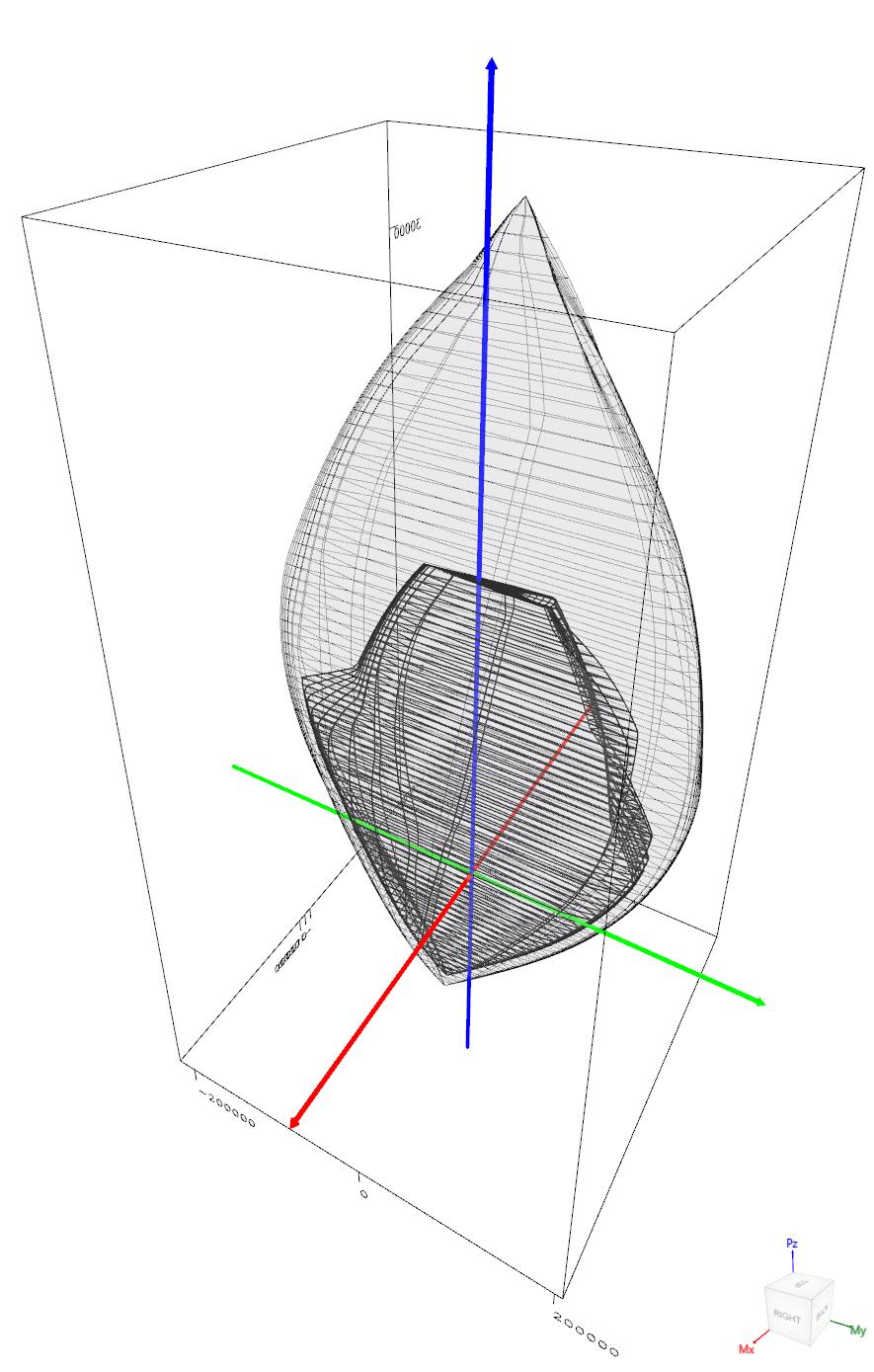
48 When running about the X-Axis, 17 layers of reinforcement are participating instead of 37 layers of reinforcement about y-axis resulting in a completely different P-M interaction diagram as shown in the following spcolumn output. The P-M diagram about x-axis is symmetrical since the section is also symmetrical. Figure 15 Comparison of Wall Interaction Diagrams about X-Axis and Y-Axis (spcolumn) In most building design calculations, such as the examples shown in the StructurePoint website, all building columns and walls are subjected to M x and M y due to lateral forces and unbalanced moments from both directions of analysis. This requires an evaluation of the column or wall P-M interaction diagram in two directions simultaneously (biaxial bending) instead of the uniaxial investigation illustrated here. StucturePoint s spcolumn program can also investigate column and wall sections in biaxial mode to produce the results shown in the following Figure for the wall section in this example. In biaxial run mode, M x and M y diagrams at each axial force level can be viewed in 2D and 3D views. 44

49 Figure 16 Nominal & Design Interaction Diagram in Two Directions (Biaxial) (spcolumn) Upon review of the model results, maximum tension strain values for the pure bending control point were deemed too high given the low assumed reinforcement ratio. A revised reinforcement arrangement was implemented as shown below: 45
50 About Point P X-Moment Y-Moment NA Depth dt Depth εt Φ kip k-ft k-ft in in Max compression fs = Allowable comp fs = 0.5 fy Balanced point Pure bending Tension control Max tension Max compression Allowable comp fs = fs = 0.5 fy Balanced point Tension control Pure bending Max tension Max compression fs = Allowable comp fs = 0.5 fy Balanced point Pure bending Tension control Max tension Max compression Allowable comp fs = fs = 0.5 fy Balanced point Tension control Pure bending Max tension
51 47
52 48
53 49
Slenderness Effects for Concrete Columns in Sway Frame - Moment Magnification Method (CSA A )
") Slenderness Effects for Concrete Columns in Sway Frame - Moment Magnification Method (CSA A23.3-94) Slender Concrete Column Design in Sway Frame Buildings Evaluate slenderness effect for columns in a
Slenderness Effects for Concrete Columns in Sway Frame - Moment Magnification Method (CSA A23.3-94) Slender Concrete Column Design in Sway Frame Buildings Evaluate slenderness effect for columns in a
Lecture-03 Design of Reinforced Concrete Members for Flexure and Axial Loads
 Lecture-03 Design of Reinforced Concrete Members for Flexure and Axial Loads By: Prof. Dr. Qaisar Ali Civil Engineering Department UET Peshawar drqaisarali@uetpeshawar.edu.pk www.drqaisarali.com Prof.
Observations in Shear Wall Strength in Tall Buildings. Presented by StructurePoint at ACI Spring 2012 Convention in Dallas, Texas
 Observations in Shear Wall Strength in Tall Buildings Presented by StructurePoint at ACI Spring 2012 Convention in Dallas, Texas 1 Metropolitan Tower, New York City 68-story, 716 ft (218m) skyscraper Reinforced
Interaction Diagram - Tied Reinforced Concrete Column (Using CSA A )
") Interaction Diagram - Tied Reinforced Concrete Column (Uing CSA A23.3-14) Interaction Diagram - Tied Reinforced Concrete Column Develop an interaction diagram for the quare tied concrete column hown in
Interaction Diagram - Tied Reinforced Concrete Column (Uing CSA A23.3-14) Interaction Diagram - Tied Reinforced Concrete Column Develop an interaction diagram for the quare tied concrete column hown in
3.5 Reinforced Concrete Section Properties
 CHAPER 3: Reinforced Concrete Slabs and Beams 3.5 Reinforced Concrete Section Properties Description his application calculates gross section moment of inertia neglecting reinforcement, moment of inertia
1/2. E c Part a The solution is identical for grade 40 and grade 60 reinforcement. P s f c n A s lbf. The steel carries 13.3 percent of the load
 1/2 3.1. A 16 20 in. column is made of the same concrete and reinforced with the same six No. 9 (No. 29) bars as the column in Examples 3.1 and 3.2, except t hat a steel with yield strength f y = 40 ksi
Design of Reinforced Concrete Beam for Shear
 Lecture 06 Design of Reinforced Concrete Beam for Shear By: Civil Engineering Department UET Peshawar drqaisarali@uetpeshawar.edu.pk Topics Addressed Shear Stresses in Rectangular Beams Diagonal Tension
Flexure: Behavior and Nominal Strength of Beam Sections
 4 5000 4000 (increased d ) (increased f (increased A s or f y ) c or b) Flexure: Behavior and Nominal Strength of Beam Sections Moment (kip-in.) 3000 2000 1000 0 0 (basic) (A s 0.5A s ) 0.0005 0.001 0.0015
Direct Design Method and Design Diagram. For Reinforced Concrete Columns and Shear walls
 Direct Design Method and Design Diagram For Reinforced Concrete Columns and Shear walls BY MAJID HOUSHIAR B.S., Isfahan University of Technology, 1988 M.S., University of Illinois at Chicago, Chicago,
Design of Reinforced Concrete Beam for Shear
 Lecture 06 Design of Reinforced Concrete Beam for Shear By: Prof Dr. Qaisar Ali Civil Engineering Department UET Peshawar drqaisarali@uetpeshawar.edu.pk 1 Topics Addressed Shear Stresses in Rectangular
Lecture-04 Design of RC Members for Shear and Torsion
 Lecture-04 Design of RC Members for Shear and Torsion By: Prof. Dr. Qaisar Ali Civil Engineering Department UET Peshawar drqaisarali@uetpeshawar.edu.pk www.drqaisarali.com 1 Topics Addressed Design of
The plastic moment capacity of a composite cross-section is calculated in the program on the following basis (BS 4.4.2):
:") COMPUTERS AND STRUCTURES, INC., BERKELEY, CALIFORNIA SEPTEMBER 2002 COMPOSITE BEAM DESIGN BS 5950-90 Technical Note Composite Plastic Moment Capacity for Positive Bending This Technical Note describes
COMPUTERS AND STRUCTURES, INC., BERKELEY, CALIFORNIA SEPTEMBER 2002 COMPOSITE BEAM DESIGN BS 5950-90 Technical Note Composite Plastic Moment Capacity for Positive Bending This Technical Note describes
Civil Engineering Design (1) Design of Reinforced Concrete Columns 2006/7
 Design of Reinforced Concrete Columns 2006/7") Civil Engineering Design (1) Design of Reinforced Concrete Columns 2006/7 Dr. Colin Caprani, Chartered Engineer 1 Contents 1. Introduction... 3 1.1 Background... 3 1.2 Failure Modes... 5 1.3 Design Aspects...
Civil Engineering Design (1) Design of Reinforced Concrete Columns 2006/7 Dr. Colin Caprani, Chartered Engineer 1 Contents 1. Introduction... 3 1.1 Background... 3 1.2 Failure Modes... 5 1.3 Design Aspects...
This Technical Note describes how the program checks column capacity or designs reinforced concrete columns when the ACI code is selected.
 COMPUTERS AND STRUCTURES, INC., BERKELEY, CALIFORNIA DECEMBER 2001 CONCRETE FRAME DESIGN ACI-318-99 Technical Note This Technical Note describes how the program checks column capacity or designs reinforced
Seismic Pushover Analysis Using AASHTO Guide Specifications for LRFD Seismic Bridge Design
 Seismic Pushover Analysis Using AASHTO Guide Specifications for LRFD Seismic Bridge Design Elmer E. Marx, Alaska Department of Transportation and Public Facilities Michael Keever, California Department
Therefore, for all members designed according to ACI 318 Code, f s =f y at failure, and the nominal strength is given by:
 5.11. Under-reinforced Beams (Read Sect. 3.4b oour text) We want the reinforced concrete beams to fail in tension because is not a sudden failure. Therefore, following Figure 5.3, you have to make sure
ε t increases from the compressioncontrolled Figure 9.15: Adjusted interaction diagram
 CHAPTER NINE COLUMNS 4 b. The modified axial strength in compression is reduced to account for accidental eccentricity. The magnitude of axial force evaluated in step (a) is multiplied by 0.80 in case
Properties of Sections
 ARCH 314 Structures I Test Primer Questions Dr.-Ing. Peter von Buelow Properties of Sections 1. Select all that apply to the characteristics of the Center of Gravity: A) 1. The point about which the body
Serviceability Deflection calculation
 Chp-6:Lecture Goals Serviceability Deflection calculation Deflection example Structural Design Profession is concerned with: Limit States Philosophy: Strength Limit State (safety-fracture, fatigue, overturning
MECHANICS OF MATERIALS Sample Problem 4.2
 Sample Problem 4. SOLUTON: Based on the cross section geometry, calculate the location of the section centroid and moment of inertia. ya ( + Y Ad ) A A cast-iron machine part is acted upon by a kn-m couple.
twenty one concrete construction: shear & deflection ARCHITECTURAL STRUCTURES: FORM, BEHAVIOR, AND DESIGN DR. ANNE NICHOLS SUMMER 2014 lecture
 ARCHITECTURAL STRUCTURES: FORM, BEHAVIOR, AND DESIGN DR. ANNE NICHOLS SUMMER 2014 lecture twenty one concrete construction: Copyright Kirk Martini shear & deflection Concrete Shear 1 Shear in Concrete
This procedure covers the determination of the moment of inertia about the neutral axis.
 327 Sample Problems Problem 16.1 The moment of inertia about the neutral axis for the T-beam shown is most nearly (A) 36 in 4 (C) 236 in 4 (B) 136 in 4 (D) 736 in 4 This procedure covers the determination
Designing Reinforced Concrete Rectangular Columns for Biaxial Bending
 ENGINEERING DATA REORT NUMBER 57 Designing Reinforced Concrete Rectangular Columns for Biaxial Bending A SERVICE OF THE CONCRETE REINFORCING STEEL INSTITUTE 933 N. lum Grove Rd., Schaumburg, Illinois 60173-4758
Reinforced Concrete Structures
 Reinforced Concrete Structures MIM 232E Dr. Haluk Sesigür I.T.U. Faculty of Architecture Structural and Earthquake Engineering WG Ultimate Strength Theory Design of Singly Reinforced Rectangular Beams
Part 1 is to be completed without notes, beam tables or a calculator. DO NOT turn Part 2 over until you have completed and turned in Part 1.
 NAME CM 3505 Fall 06 Test 2 Part 1 is to be completed without notes, beam tables or a calculator. Part 2 is to be completed after turning in Part 1. DO NOT turn Part 2 over until you have completed and
Ch. 10 Design of Short Columns Subject to Axial Load and Bending
 Ch. 10 Design o Short Columns Subjet to Axial Load and Bending Axial Loading and Bending Development o Interation Diagram Column Design Using P-M Interation Diagram Shear in Columns Biaxial Bending Examples
CHAPTER 6: ULTIMATE LIMIT STATE
 CHAPTER 6: ULTIMATE LIMIT STATE 6.1 GENERAL It shall be in accordance with JSCE Standard Specification (Design), 6.1. The collapse mechanism in statically indeterminate structures shall not be considered.
SERVICEABILITY OF BEAMS AND ONE-WAY SLABS
 CHAPTER REINFORCED CONCRETE Reinforced Concrete Design A Fundamental Approach - Fifth Edition Fifth Edition SERVICEABILITY OF BEAMS AND ONE-WAY SLABS A. J. Clark School of Engineering Department of Civil
MECHANICS OF MATERIALS. Prepared by Engr. John Paul Timola
 MECHANICS OF MATERIALS Prepared by Engr. John Paul Timola Mechanics of materials branch of mechanics that studies the internal effects of stress and strain in a solid body. stress is associated with the
Annex - R C Design Formulae and Data
 The design formulae and data provided in this Annex are for education, training and assessment purposes only. They are based on the Hong Kong Code of Practice for Structural Use of Concrete 2013 (HKCP-2013).
Lecture-05 Serviceability Requirements & Development of Reinforcement
 Lecture-05 Serviceability Requirements & Development of Reinforcement By: Prof Dr. Qaisar Ali Civil Engineering Department UET Peshawar drqaisarali@uetpeshawar.edu.pk www.drqaisarali.com 1 Section 1: Deflections
A Study on Behaviour of Symmetrical I-Shaped Column Using Interaction Diagram
 A Study on Behaviour of Symmetrical I-Shaped Column Using Interaction Diagram Sudharma.V.S.Acharya 1, R.M. Subrahmanya 2, B.G. Naresh Kumar 3, Shanmukha Shetty 4, Smitha 5 P.G. Student, Department of Civil
Biaxial Analysis of General Shaped Base Plates
 Biaxial Analysis of General Shaped Base Plates R. GONZALO ORELLANA 1 Summary: A linear model is used for the contact stresses calculation between a steel base plate and a concrete foundation. It is also
Bending and Shear in Beams
 Bending and Shear in Beams Lecture 3 5 th October 017 Contents Lecture 3 What reinforcement is needed to resist M Ed? Bending/ Flexure Section analysis, singly and doubly reinforced Tension reinforcement,
Purpose of this Guide: To thoroughly prepare students for the exact types of problems that will be on Exam 3.
 ES230 STRENGTH OF MTERILS Exam 3 Study Guide Exam 3: Wednesday, March 8 th in-class Updated 3/3/17 Purpose of this Guide: To thoroughly prepare students for the exact types of problems that will be on
3.4 Reinforced Concrete Beams - Size Selection
 CHAPER 3: Reinforced Concrete Slabs and Beams 3.4 Reinforced Concrete Beams - Size Selection Description his application calculates the spacing for shear reinforcement of a concrete beam supporting a uniformly
LIMITATIONS OF THE STANDARD INTERACTION FORMULA FOR BIAXIAL BENDING AS APPLIED TO RECTANGULAR STEEL TUBULAR COLUMNS
 LIMITATIONS OF THE STANDARD INTERACTION FORMULA FOR BIAXIAL BENDING AS APPLIED TO RECTANGULAR STEEL TUBULAR COLUMNS Ramon V. Jarquio 1 ABSTRACT The limitations of the standard interaction formula for biaxial
Chapter. Materials. 1.1 Notations Used in This Chapter
 Chapter 1 Materials 1.1 Notations Used in This Chapter A Area of concrete cross-section C s Constant depending on the type of curing C t Creep coefficient (C t = ε sp /ε i ) C u Ultimate creep coefficient
Design of a Multi-Storied RC Building
 Design of a Multi-Storied RC Building 16 14 14 3 C 1 B 1 C 2 B 2 C 3 B 3 C 4 13 B 15 (S 1 ) B 16 (S 2 ) B 17 (S 3 ) B 18 7 B 4 B 5 B 6 B 7 C 5 C 6 C 7 C 8 C 9 7 B 20 B 22 14 B 19 (S 4 ) C 10 C 11 B 23
Column Design. Columns Axial Load and Bending
 Column Design MORGAN STATE UNIVERSITY SCHOOL OF ARCHITECTURE AND PLANNING LECTURE VI Dr. Jason E. Charalambides = = Columns Axial Load and Bending We tend to have this image of columns that we envision
CONSULTING Engineering Calculation Sheet. Job Title Member Design - Reinforced Concrete Column BS8110
 E N G I N E E R S Consulting Engineers jxxx 1 Job Title Member Design - Reinforced Concrete Column Effects From Structural Analysis Axial force, N (tension-ve and comp +ve) (ensure >= 0) 8000kN OK Major
Appendix J. Example of Proposed Changes
 Appendix J Example of Proposed Changes J.1 Introduction The proposed changes are illustrated with reference to a 200-ft, single span, Washington DOT WF bridge girder with debonded strands and no skew.
Lap splice length and details of column longitudinal reinforcement at plastic hinge region
 Lap length and details of column longitudinal reinforcement at plastic hinge region Hong-Gun Park 1) and Chul-Goo Kim 2) 1), 2 Department of Architecture and Architectural Engineering, Seoul National University,
Chapter 8. Shear and Diagonal Tension
 Chapter 8. and Diagonal Tension 8.1. READING ASSIGNMENT Text Chapter 4; Sections 4.1-4.5 Code Chapter 11; Sections 11.1.1, 11.3, 11.5.1, 11.5.3, 11.5.4, 11.5.5.1, and 11.5.6 8.2. INTRODUCTION OF SHEAR
Derivation of minimum steel ratio: based on service applied stresses
 MATEC Web of Conferences, () DOI:./ matecconf/ Derivation of minimum steel ratio: based on service applied stresses Humam AL Sebai,*, Salah Al Toubat University of Sharjah, Sharjah city, UAE Abstract.
CHAPTER 4: BENDING OF BEAMS
 (74) CHAPTER 4: BENDING OF BEAMS This chapter will be devoted to the analysis of prismatic members subjected to equal and opposite couples M and M' acting in the same longitudinal plane. Such members are
Appendix G Analytical Studies of Columns
 Appendix G Analytical Studies of Columns G.1 Introduction Analytical parametric studies were performed to evaluate a number of issues related to the use of ASTM A103 steel as longitudinal and transverse
A q u a b l u e a t t h e G o l d e n M i l e
 A q u a b l u e a t t h e G o l d e n M i l e H a t o R e y, P u e r t o R i c o G e n e r a l B u i l d i n g I n f o r m a t i o n Building Facts: 7-story parking structure + luxury apartments 900,000
Generation of Biaxial Interaction Surfaces
 COPUTERS AND STRUCTURES, INC., BERKELEY, CALIFORNIA AUGUST 2002 CONCRETE FRAE DESIGN BS 8110-97 Technical Note This Technical Note describes how the program checks column capacity or designs reinforced
Why are We Here? AASHTO LRFD Bridge Design Specifications Metal Pipe Section 12.7 Concrete Pipe Section Plastic Pipe Section 12.12
 Direct Design and Indirect Design of Concrete Pipe Part 1 Josh Beakley March 2011 Why are We Here? AASHTO LRFD Bridge Design Specifications Metal Pipe Section 12.7 Concrete Pipe Section 12.10 Plastic Pipe
Appendix K Design Examples
 Appendix K Design Examples Example 1 * Two-Span I-Girder Bridge Continuous for Live Loads AASHTO Type IV I girder Zero Skew (a) Bridge Deck The bridge deck reinforcement using A615 rebars is shown below.
Sway Column Example. PCA Notes on ACI 318
 Sway Column Example PCA Notes on ACI 318 ASDIP Concrete is available for purchase online at www.asdipsoft.com Example 11.2 Slenderness Effects for Columns in a Sway Frame Design columns C1 and C2 in the
MECHANICS OF MATERIALS
 Third E CHAPTER 6 Shearing MECHANCS OF MATERALS Ferdinand P. Beer E. Russell Johnston, Jr. John T. DeWolf Lecture Notes: J. Walt Oler Texas Tech University Stresses in Beams and Thin- Walled Members Shearing
PLATE GIRDERS II. Load. Web plate Welds A Longitudinal elevation. Fig. 1 A typical Plate Girder
 16 PLATE GIRDERS II 1.0 INTRODUCTION This chapter describes the current practice for the design of plate girders adopting meaningful simplifications of the equations derived in the chapter on Plate Girders
Slenderness Effects for Concrete Columns in Sway Frame - Moment Magnification Method
 Slenderness Effets for Conrete Columns in Sway Frame - Moment Magnifiation Method Slender Conrete Column Design in Sway Frame Buildings Evaluate slenderness effet for olumns in a sway frame multistory
999 TOWN & COUNTRY ROAD ORANGE, CALIFORNIA TITLE PUSHOVER ANALYSIS EXAMPLE BY R. MATTHEWS DATE 5/21/01
 DESCRIPTION Nonlinear static (pushover) analysis will be performed on a railroad bridge bent using several methods to determine its ultimate lateral deflection capability. 1. SAP2000 Nonlinear with axial-moment
Slenderness Effects for Concrete Columns in Sway Frame - Moment Magnification Method
 Slenderness Effets for Conrete Columns in Sway Frame - Moment Magnifiation Method Slender Conrete Column Design in Sway Frame Buildings Evaluate slenderness effet for olumns in a sway frame multistory
Failure interaction curves for combined loading involving torsion, bending, and axial loading
 Failure interaction curves for combined loading involving torsion, bending, and axial loading W M Onsongo Many modern concrete structures such as elevated guideways are subjected to combined bending, torsion,
MECE 3321 MECHANICS OF SOLIDS CHAPTER 3
 MECE 3321 MECHANICS OF SOLIDS CHAPTER 3 Samantha Ramirez TENSION AND COMPRESSION TESTS Tension and compression tests are used primarily to determine the relationship between σ avg and ε avg in any material.
Steel Cross Sections. Structural Steel Design
 Steel Cross Sections Structural Steel Design PROPERTIES OF SECTIONS Perhaps the most important properties of a beam are the depth and shape of its cross section. There are many to choose from, and there
UNIVERSITY OF SASKATCHEWAN ME MECHANICS OF MATERIALS I FINAL EXAM DECEMBER 13, 2008 Professor A. Dolovich
 UNIVERSITY OF SASKATCHEWAN ME 313.3 MECHANICS OF MATERIALS I FINAL EXAM DECEMBER 13, 2008 Professor A. Dolovich A CLOSED BOOK EXAMINATION TIME: 3 HOURS For Marker s Use Only LAST NAME (printed): FIRST
9.5 Compression Members
 9.5 Compression Members This section covers the following topics. Introduction Analysis Development of Interaction Diagram Effect of Prestressing Force 9.5.1 Introduction Prestressing is meaningful when
Mechanics of Materials Primer
 Mechanics of Materials rimer Notation: A = area (net = with holes, bearing = in contact, etc...) b = total width of material at a horizontal section d = diameter of a hole D = symbol for diameter E = modulus
CHAPTER 4. ANALYSIS AND DESIGN OF COLUMNS
 4.1. INTRODUCTION CHAPTER 4. ANALYSIS AND DESIGN OF COLUMNS A column is a vertical structural member transmitting axial compression loads with or without moments. The cross sectional dimensions of a column
5. What is the moment of inertia about the x - x axis of the rectangular beam shown?
 1 of 5 Continuing Education Course #274 What Every Engineer Should Know About Structures Part D - Bending Strength Of Materials NOTE: The following question was revised on 15 August 2018 1. The moment
Chapter 3. Load and Stress Analysis
 Chapter 3 Load and Stress Analysis 2 Shear Force and Bending Moments in Beams Internal shear force V & bending moment M must ensure equilibrium Fig. 3 2 Sign Conventions for Bending and Shear Fig. 3 3
4.3 Moment Magnification
 CHAPTER 4: Reinforced Concrete Columns 4.3 Moment Magnification Description An ordinary or first order frame analysis does not include either the effects of the lateral sidesway deflections of the column
Direct Design and Indirect Design of Concrete Pipe Part 2 Josh Beakley March 2011
 Direct Design and Indirect Design of Concrete Pipe Part 2 Josh Beakley March 2011 Latest in Design Methods? AASHTO LRFD Bridge Design Specifications 2010 Direct Design Method for Concrete Pipe 1993? LRFD5732FlexuralResistance
Karbala University College of Engineering Department of Civil Eng. Lecturer: Dr. Jawad T. Abodi
 Chapter 05 Structural Steel Design According to the AISC Manual 13 th Edition Analysis and Design of Beams By Dr. Jawad Talib Al-Nasrawi University of Karbala Department of Civil Engineering 71 Introduction
Lecture-08 Gravity Load Analysis of RC Structures
 Lecture-08 Gravity Load Analysis of RC Structures By: Prof Dr. Qaisar Ali Civil Engineering Department UET Peshawar www.drqaisarali.com 1 Contents Analysis Approaches Point of Inflection Method Equivalent
CHAPTER 4. Design of R C Beams
 CHAPTER 4 Design of R C Beams Learning Objectives Identify the data, formulae and procedures for design of R C beams Design simply-supported and continuous R C beams by integrating the following processes
A METHOD OF LOAD INCREMENTS FOR THE DETERMINATION OF SECOND-ORDER LIMIT LOAD AND COLLAPSE SAFETY OF REINFORCED CONCRETE FRAMED STRUCTURES
 A METHOD OF LOAD INCREMENTS FOR THE DETERMINATION OF SECOND-ORDER LIMIT LOAD AND COLLAPSE SAFETY OF REINFORCED CONCRETE FRAMED STRUCTURES Konuralp Girgin (Ph.D. Thesis, Institute of Science and Technology,
APPENDIX 1 MODEL CALCULATION OF VARIOUS CODES
 163 APPENDIX 1 MODEL CALCULATION OF VARIOUS CODES A1.1 DESIGN AS PER NORTH AMERICAN SPECIFICATION OF COLD FORMED STEEL (AISI S100: 2007) 1. Based on Initiation of Yielding: Effective yield moment, M n
A Simply supported beam with a concentrated load at mid-span: Loading Stages
 A Simply supported beam with a concentrated load at mid-span: Loading Stages P L/2 L PL/4 MOMNT F b < 1 lastic F b = 2 lastic F b = 3 lastoplastic 4 F b = Plastic hinge Plastic Dr. M.. Haque, P.. (LRFD:
Problem d d d B C E D. 0.8d. Additional lecturebook examples 29 ME 323
 Problem 9.1 Two beam segments, AC and CD, are connected together at C by a frictionless pin. Segment CD is cantilevered from a rigid support at D, and segment AC has a roller support at A. a) Determine
ERRATA for PE Civil Structural Practice Exam ISBN Copyright 2014 (July 2016 Second Printing) Errata posted
 Errata posted") Errata posted 8-16-2017 Revisions are shown in red. Question 521, p. 47: Question 521 should read as follows: 521. The W10 22 steel eam (Fy = 50 ksi) shown in the figure is only raced at the center of
Errata posted 8-16-2017 Revisions are shown in red. Question 521, p. 47: Question 521 should read as follows: 521. The W10 22 steel eam (Fy = 50 ksi) shown in the figure is only raced at the center of
ME Final Exam. PROBLEM NO. 4 Part A (2 points max.) M (x) y. z (neutral axis) beam cross-sec+on. 20 kip ft. 0.2 ft. 10 ft. 0.1 ft.
 M (x) y. z (neutral axis) beam cross-sec+on. 20 kip ft. 0.2 ft. 10 ft. 0.1 ft.") ME 323 - Final Exam Name December 15, 2015 Instructor (circle) PROEM NO. 4 Part A (2 points max.) Krousgrill 11:30AM-12:20PM Ghosh 2:30-3:20PM Gonzalez 12:30-1:20PM Zhao 4:30-5:20PM M (x) y 20 kip ft 0.2
ME 323 - Final Exam Name December 15, 2015 Instructor (circle) PROEM NO. 4 Part A (2 points max.) Krousgrill 11:30AM-12:20PM Ghosh 2:30-3:20PM Gonzalez 12:30-1:20PM Zhao 4:30-5:20PM M (x) y 20 kip ft 0.2
[5] Stress and Strain
![[5] Stress and Strain](/thumbs/95/123344550.jpg "[5] Stress and Strain") [5] Stress and Strain Page 1 of 34 [5] Stress and Strain [5.1] Internal Stress of Solids [5.2] Design of Simple Connections (will not be covered in class) [5.3] Deformation and Strain [5.4] Hooke s Law
[5] Stress and Strain Page 1 of 34 [5] Stress and Strain [5.1] Internal Stress of Solids [5.2] Design of Simple Connections (will not be covered in class) [5.3] Deformation and Strain [5.4] Hooke s Law
2010 NASCC / Structures Congress Orlando, Florida May 13, 2010
 2010 NASCC / Structures Congress Orlando, Florida May 13, 2010 Load Transfer in Composite Construction (Chapter I of the 2010 AISC Specification) William P. Jacobs, V Stanley D. Lindsey & Associates Atlanta,
ORIGIN 0. PTC_CE_BSD_7.2_us_mp.mcdx. Mathcad Enabled Content Copyright 2011 Knovel Corp.
 PC_CE_BSD_7._us_mp.mcdx Copyright 011 Knovel Corp. Building Structural Design homas P. Magner, P.E. 011 Parametric echnology Corp. Chapter 7: Reinforced Concrete Column and Wall Footings 7. Pile Footings
Accordingly, the nominal section strength [resistance] for initiation of yielding is calculated by using Equation C-C3.1.
![Accordingly, the nominal section strength [resistance] for initiation of yielding is calculated by using Equation C-C3.1.](/thumbs/89/98617066.jpg "Accordingly, the nominal section strength [resistance] for initiation of yielding is calculated by using Equation C-C3.1.") C3 Flexural Members C3.1 Bending The nominal flexural strength [moment resistance], Mn, shall be the smallest of the values calculated for the limit states of yielding, lateral-torsional buckling and distortional
C3 Flexural Members C3.1 Bending The nominal flexural strength [moment resistance], Mn, shall be the smallest of the values calculated for the limit states of yielding, lateral-torsional buckling and distortional
Chapter 8: Bending and Shear Stresses in Beams
 Chapter 8: Bending and Shear Stresses in Beams Introduction One of the earliest studies concerned with the strength and deflection of beams was conducted by Galileo Galilei. Galileo was the first to discuss
Mechanics of Materials
 Mechanics of Materials Notation: a = acceleration = area (net = with holes, bearing = in contact, etc...) SD = allowable stress design d = diameter of a hole = calculus symbol for differentiation e = change
PUNCHING SHEAR CALCULATIONS 1 ACI 318; ADAPT-PT
 Structural Concrete Software System TN191_PT7_punching_shear_aci_4 011505 PUNCHING SHEAR CALCULATIONS 1 ACI 318; ADAPT-PT 1. OVERVIEW Punching shear calculation applies to column-supported slabs, classified
Lab Exercise #5: Tension and Bending with Strain Gages
 Lab Exercise #5: Tension and Bending with Strain Gages Pre-lab assignment: Yes No Goals: 1. To evaluate tension and bending stress models and Hooke s Law. a. σ = Mc/I and σ = P/A 2. To determine material
CE5510 Advanced Structural Concrete Design - Design & Detailing of Openings in RC Flexural Members-
 CE5510 Advanced Structural Concrete Design - Design & Detailing Openings in RC Flexural Members- Assoc Pr Tan Kiang Hwee Department Civil Engineering National In this lecture DEPARTMENT OF CIVIL ENGINEERING
Beam Bending Stresses and Shear Stress
 Beam Bending Stresses and Shear Stress Notation: A = name or area Aweb = area o the web o a wide lange section b = width o a rectangle = total width o material at a horizontal section c = largest distance
PEER/SSC Tall Building Design. Case study #2
 PEER/SSC Tall Building Design Case study #2 Typical Plan View at Ground Floor and Below Typical Plan View at 2 nd Floor and Above Code Design Code Design Shear Wall properties Shear wall thickness and
twenty one concrete construction: materials & beams ELEMENTS OF ARCHITECTURAL STRUCTURES: FORM, BEHAVIOR, AND DESIGN DR. ANNE NICHOLS SPRING 2014
 ELEMENTS OF ARCHITECTURAL STRUCTURES: FORM, BEHAVIOR, AND DESIGN DR. ANNE NICHOLS SPRING 2014 lecture twenty one concrete construction: http:// nisee.berkeley.edu/godden materials & beams Concrete Beams
Case Study in Reinforced Concrete adapted from Simplified Design of Concrete Structures, James Ambrose, 7 th ed.
 ARCH 631 Note Set 11 S017abn Case Study in Reinforced Concrete adapted from Simplified Design of Concrete Structures, James Ambrose, 7 th ed. Building description The building is a three-story office building
Advanced Structural Analysis EGF Section Properties and Bending
 Advanced Structural Analysis EGF316 3. Section Properties and Bending 3.1 Loads in beams When we analyse beams, we need to consider various types of loads acting on them, for example, axial forces, shear
UNSYMMETRICAL BENDING
 UNSYMMETRICAL BENDING The general bending stress equation for elastic, homogeneous beams is given as (II.1) where Mx and My are the bending moments about the x and y centroidal axes, respectively. Ix and
[8] Bending and Shear Loading of Beams
![[8] Bending and Shear Loading of Beams](/thumbs/92/110949676.jpg "[8] Bending and Shear Loading of Beams") [8] Bending and Shear Loading of Beams Page 1 of 28 [8] Bending and Shear Loading of Beams [8.1] Bending of Beams (will not be covered in class) [8.2] Bending Strain and Stress [8.3] Shear in Straight
[8] Bending and Shear Loading of Beams Page 1 of 28 [8] Bending and Shear Loading of Beams [8.1] Bending of Beams (will not be covered in class) [8.2] Bending Strain and Stress [8.3] Shear in Straight
MODELING OF NONLINEAR BEHAVIOR OF RC SHEAR WALLS UNDER COMBINED AXIAL, SHEAR AND FLEXURAL LOADING
 CD02-003 MODELING OF NONLINEAR BEHAVIOR OF RC SHEAR WALLS UNDER COMBINED AXIAL, SHEAR AND FLEXURAL LOADING B. Ghiassi 1, M. Soltani 2, A. A. Tasnimi 3 1 M.Sc. Student, School of Engineering, Tarbiat Modares
Design of Steel Structures Prof. S.R.Satish Kumar and Prof. A.R.Santha Kumar. Local buckling is an extremely important facet of cold formed steel
 5.3 Local buckling Local buckling is an extremely important facet of cold formed steel sections on account of the fact that the very thin elements used will invariably buckle before yielding. Thinner the
Design of Reinforced Concrete Structures (II)
") Design of Reinforced Concrete Structures (II) Discussion Eng. Mohammed R. Kuheil Review The thickness of one-way ribbed slabs After finding the value of total load (Dead and live loads), the elements are
Design of Reinforced Concrete Structures (II) Discussion Eng. Mohammed R. Kuheil Review The thickness of one-way ribbed slabs After finding the value of total load (Dead and live loads), the elements are
APPENDIX G I-BEAM SUMMARIES 0.6-IN. STRAND G-1
 APPENDIX G I-BEAM SUMMARIES.6-IN. STRAND G-1 Concrete Compressive Strength Embedment Length(L e ) Span Failure Mode Maximum Load Maximum Shear Maximum Moment Maximum Deflection attained Rebound after complete
Behavior and Modeling of Existing Reinforced Concrete Columns
 Behavior and Modeling of Existing Reinforced Concrete Columns Kenneth J. Elwood University of British Columbia with contributions from Jose Pincheira, Univ of Wisconsin John Wallace, UCLA Questions? What
FLEXURAL ANALYSIS AND DESIGN METHODS FOR SRC BEAM SECTIONS WITH COMPLETE COMPOSITE ACTION
 Journal of the Chinese Institute of Engineers, Vol. 31, No., pp. 15-9 (8) 15 FLEXURAL ANALYSIS AND DESIGN METHODS FOR SRC BEAM SECTIONS WITH COMPLETE COMPOSITE ACTION Cheng-Cheng Chen* and Chao-Lin Cheng
Edward C. Robison, PE, SE. 02 January Architectural Metal Works ATTN: Sean Wentworth th ST Emeryville, CA 94608
 Edward C. Robison, PE, SE ks ATTN: Sean Wentworth 1483 67 th ST Emeryville, CA 94608 02 January 2013 SUBJ: 501 CORTE MADERA AVE, CORTE MADERA, CA 94925 BALCONY GUARD BASE PLATE MOUNTS The guards for the