Beam Bending Stresses and Shear Stress
|
|
|
- Christiana West
- 6 years ago
- Views:
Transcription
1 Beam Bending Stresses and Shear Stress Notation: A = name or area Aweb = area o the web o a wide lange section b = width o a rectangle = total width o material at a horizontal section c = largest distance rom the neutral axis to the top or bottom edge o a beam d = calculus symbol or dierentiation = depth o a wide lange section dy = dierence in the y direction between an area centroid ( ) and the centroid o the composite shape ( ) DL = shorthand or dead load E = modulus o elasticity or Young s modulus b = bending stress c = compressive stress max = maximum stress t = tensile stress v = shear stress Fb = allowable bending stress Fconnector = shear orce capacity per connector h = height o a rectangle = moment o inertia with respect to neutral axis bending x = moment o inertia with respect to an x-axis L = name or length LL = shorthand or live load M = internal bending moment = name or a moment vector y ŷ n = number o connectors across a joint n.a. = shorthand or neutral axis (N.A.) O = name or reerence origin p = pitch o connector spacing P = name or a orce vector q = shear per length (shear low) Q = irst moment area about a neutral axis Qconnected = irst moment area about a neutral axis or the connected part R = radius o curvature o a deormed beam S = section modulus Sreq d = section modulus required at allowable stress tw = thickness o web o wide lange = internal shear orce longitudinal = longitudinal shear orce T = transverse shear orce w = name or distributed load x = horizontal distance y = vertical distance y = the distance in the y direction rom a reerence axis (n.a) to the centroid o a shape = the distance in the y direction rom a reerence axis to the centroid o a composite shape = calculus symbol or small quantity = elongation or length change = strain = arc angle = summation symbol ŷ 185


2 Pure Bending in Beams With bending moments along the axis o the member only, a beam is said to be in pure bending. Normal stresses due to bending can be ound or homogeneous materials having a plane o symmetry in the y axis that ollow Hooke s law. y Maximum Moment and Stress Distribution x n a member o constant cross section, the maximum bending moment will govern the design o the section size when we know what kind o normal stress is caused by it. For internal equilibrium to be maintained, the bending moment will be equal to the M rom the normal stresses the areas the moment arms. Geometric it helps solve this statically indeterminate problem: 1. The normal planes remain normal or pure bending.. There is no net internal axial orce. 3. Stress varies linearly over cross section. 4. Zero stress exists at the centroid and the line o centroids is the neutral axis (n. a) 186

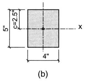
3 Relations or Beam Geometry and Stress Pure bending results in a circular arc delection. R is the distance to the center o the arc; is the angle o the arc (radians); c is the distance rom the n.a. to the extreme iber; is a length change; max is the maximum normal stress at the extreme iber; y is a distance in y rom the n.a.; M is the bending moment; is the moment o inertia; S is the section modulus. L R M i A i My b L R M max c y i A i max Now: or a rectangle o height h and width b: E y A y c c S ½ c R L y ½ Mc max 3 bh bh S 1 h 6 M S RELATONS: 1 * M R E My b S c b max Mc M S S required M F b *Note: y positive goes DOWN. With a positive M and y to the bottom iber as positive, it results in a TENSON stress (we ve called positive) Transverse Loading in Beams We are aware that transverse beam loadings result in internal shear and bending moments. We designed sections based on bending stresses, since this stress dominates beam behavior. There can be shear stresses horizontally within a beam member. t can be shown that horizontal vertical 187


4 Equilibrium and Derivation n order or equilibrium or any element CDD C, there needs to be a horizontal orce H. D da C da Q is a moment area with respect to the neutral axis o the area above or below the horizontal where the H occurs. Q is a maximum when y = 0 (at the neutral axis). longitudinal T Q x q is a horizontal shear per unit length shear low Shearing Stresses q longitudinal x T Q v ave = 0 on the beam s surace. Even i Q is a maximum at y = 0, we don t know that the thickness is a minimum there. v A b x vave Q b Rectangular Sections occurs at the neutral axis: vmax then: 3 bh 1 Q Q 1 8 bh 3 v 3 b 1 bh b bh 1 Ay b h 1 h bh 3 v A 8 188


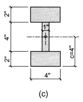
5 Webs o Beams n steel W or S sections the thickness varies rom the lange to the web. d We neglect the shear stress in the langes and consider the shear stress in the web to be constant: tw vmax 3 A A web vmax t d web Webs o beams can ail in tension shear across a panel with stieners or the web can buckle. Shear Flow Even i the cut we make to ind Q is not horizontal, but arbitrary, we can still ind the shear low, q, as long as the loads on thin-walled sections are applied in a plane o symmetry, and the cut is made perpendicular to the surace o the member. Q q The shear low magnitudes can be sketched by knowing Q. 189
 can be determined by the capacity in shear o the connector(s) to the shear over the spacing interval, p. x y 4.")

 to the shear low over the spacing interval, p.")
6 Connectors to Resist Horizontal Shear in Composite Members Typical connections needing to resist shear are plates with nails or rivets or bolts in composite sections or splices. The pitch (spacing) can be determined by the capacity in shear o the connector(s) to the shear over the spacing interval, p. x y 4.43 ya low p p p where p = pitch length longitudinal Q n = number o connectors connecting the connected area to the rest o the cross section F = orce capacity in one connector p nf connector Q connected area longitudinal p Q p Qconnected area = Aconnected area yconnected area yconnected area = distance rom the centroid o the connected area to the neutral axis Connectors to Resist Horizontal Shear in Composite Members Even vertical connectors have shear low across them. p p p The spacing can be determined by the capacity in shear o the connector(s) to the shear low over the spacing interval, p. nf p Q connector connected area Unsymmetrical Sections or Shear the section is not symmetric, or has a shear not in that plane, the member can bend and twist. the load is applied at the shear center there will not be twisting. This is the location where the moment caused by shear low = the moment o the shear orce about the shear center. 190
")
7 Example 1 (pg 37) 191
8 Example * (pg 377), and evaluate the shear stress i F v = 95 psi. Roo: Snow +DL = 00 lb/t Walls: 400 lb on nd loor beams Railing: 100 lb on beam overhang Second Floor: DL + LL = 300 lb/t (including overhang) Roo: *ALSO select the most economical steel section or the second-loor when S req d is 165 in 3 and evaluate the shear stress when = 60 k. Second Floor: 19
9 Example 3 (pg 386) ALSO: Determine the minimum nail spacing required (pitch) i the shear capacity o a nail (F connector) is 50 lb
 = 83.8 in 3 3 (, 600 #)( 83. 8in. ) 181. psi vmax 4 1 1 ( 1, 0. 6in. )( \" \") (n) (n) (n) (n)f p (n)f p 194")
10 y= 4.5" ARCH 331 Note Set 10.1 Su016abn Example 4 (pg394 Q = Ay = (9")(½")(4.5")+(9")(½")(4.5")+(1.5")(3.5")(8.5") = 83.8 in 3 3 (, 600 #)( 83. 8in. ) 181. psi vmax ( 1, 0. 6in. )( " ") (n) (n) (n) (n)f p (n)f p 194
Beam Stresses Bending and Shear
 Beam Stresses Bending and Shear Notation: A = name or area A web = area o the web o a wide lange setion b = width o a retangle = total width o material at a horizontal setion = largest distane rom the
Mechanics of Materials Primer
 Mechanics of Materials rimer Notation: A = area (net = with holes, bearing = in contact, etc...) b = total width of material at a horizontal section d = diameter of a hole D = symbol for diameter E = modulus
[8] Bending and Shear Loading of Beams
![[8] Bending and Shear Loading of Beams](/thumbs/92/110949676.jpg "[8] Bending and Shear Loading of Beams") [8] Bending and Shear Loading of Beams Page 1 of 28 [8] Bending and Shear Loading of Beams [8.1] Bending of Beams (will not be covered in class) [8.2] Bending Strain and Stress [8.3] Shear in Straight
[8] Bending and Shear Loading of Beams Page 1 of 28 [8] Bending and Shear Loading of Beams [8.1] Bending of Beams (will not be covered in class) [8.2] Bending Strain and Stress [8.3] Shear in Straight
two structural analysis (statics & mechanics) Structural Requirements Structure Requirements Structure Requirements serviceability efficiency
 Structural Requirements Structure Requirements Structure Requirements serviceability efficiency") LIED RCHITECTURL STRUCTURES: STRUCTURL NLYSIS ND SYSTEMS DR. NNE NICHOLS SRING 018 lecture two structural analysis (statics & mechanics) nalysis 1 pplied rchitectural Structures 009abn Structural Requirements
LIED RCHITECTURL STRUCTURES: STRUCTURL NLYSIS ND SYSTEMS DR. NNE NICHOLS SRING 018 lecture two structural analysis (statics & mechanics) nalysis 1 pplied rchitectural Structures 009abn Structural Requirements
UNIT- I Thin plate theory, Structural Instability:
 UNIT- I Thin plate theory, Structural Instability: Analysis of thin rectangular plates subject to bending, twisting, distributed transverse load, combined bending and in-plane loading Thin plates having
Advanced Structural Analysis EGF Section Properties and Bending
 Advanced Structural Analysis EGF316 3. Section Properties and Bending 3.1 Loads in beams When we analyse beams, we need to consider various types of loads acting on them, for example, axial forces, shear
CO~RSEOUTL..INE. revisedjune 1981 by G. Frech. of..a.pqij~t(..~ttsa.fidteconol.q.gy. Sault ",Ste'...:M~ri,e.: SAUl. ir.ft\,nl~t';~l' G ". E b:.
 -/ 1/ /.. SAUl. ir.ft\,nl~t';~l' G ". E b:.~~~~~, of..a.pqij~t(..~ttsa.fidteconol.q.gy. Sault ",Ste'...:M~ri,e.: ',' -.\'~. ~ ;:T.., CO~RSEOUTL..INE ARCHITECTURAL ENGINEERING II ARC 200-4 revisedjune 1981
Chapter 6: Cross-Sectional Properties of Structural Members
 Chapter 6: Cross-Sectional Properties of Structural Members Introduction Beam design requires the knowledge of the following. Material strengths (allowable stresses) Critical shear and moment values Cross
3. BEAMS: STRAIN, STRESS, DEFLECTIONS
 3. BEAMS: STRAIN, STRESS, DEFLECTIONS The beam, or flexural member, is frequently encountered in structures and machines, and its elementary stress analysis constitutes one of the more interesting facets
two structural analysis (statics & mechanics) APPLIED ACHITECTURAL STRUCTURES: DR. ANNE NICHOLS SPRING 2017 lecture STRUCTURAL ANALYSIS AND SYSTEMS
 APPLIED ACHITECTURAL STRUCTURES: DR. ANNE NICHOLS SPRING 2017 lecture STRUCTURAL ANALYSIS AND SYSTEMS") APPLIED ACHITECTURAL STRUCTURES: STRUCTURAL ANALYSIS AND SYSTEMS DR. ANNE NICHOLS SPRING 2017 lecture two structural analysis (statics & mechanics) Analysis 1 Structural Requirements strength serviceability
APPLIED ACHITECTURAL STRUCTURES: STRUCTURAL ANALYSIS AND SYSTEMS DR. ANNE NICHOLS SPRING 2017 lecture two structural analysis (statics & mechanics) Analysis 1 Structural Requirements strength serviceability
Properties of Sections
 ARCH 314 Structures I Test Primer Questions Dr.-Ing. Peter von Buelow Properties of Sections 1. Select all that apply to the characteristics of the Center of Gravity: A) 1. The point about which the body
Lecture 15 Strain and stress in beams
 Spring, 2019 ME 323 Mechanics of Materials Lecture 15 Strain and stress in beams Reading assignment: 6.1 6.2 News: Instructor: Prof. Marcial Gonzalez Last modified: 1/6/19 9:42:38 PM Beam theory (@ ME
PURE BENDING. If a simply supported beam carries two point loads of 10 kn as shown in the following figure, pure bending occurs at segment BC.
 BENDING STRESS The effect of a bending moment applied to a cross-section of a beam is to induce a state of stress across that section. These stresses are known as bending stresses and they act normally
twenty one concrete construction: shear & deflection ARCHITECTURAL STRUCTURES: FORM, BEHAVIOR, AND DESIGN DR. ANNE NICHOLS SUMMER 2014 lecture
 ARCHITECTURAL STRUCTURES: FORM, BEHAVIOR, AND DESIGN DR. ANNE NICHOLS SUMMER 2014 lecture twenty one concrete construction: Copyright Kirk Martini shear & deflection Concrete Shear 1 Shear in Concrete
CHAPTER 6: Shearing Stresses in Beams
 (130) CHAPTER 6: Shearing Stresses in Beams When a beam is in pure bending, the only stress resultants are the bending moments and the only stresses are the normal stresses acting on the cross sections.
CHAPTER -6- BENDING Part -1-
 Ishik University / Sulaimani Civil Engineering Department Mechanics of Materials CE 211 CHAPTER -6- BENDING Part -1-1 CHAPTER -6- Bending Outlines of this chapter: 6.1. Chapter Objectives 6.2. Shear and
Stresses in Curved Beam
 Stresses in Curved Beam Consider a curved beam subjected to bending moment M b as shown in the figure. The distribution of stress in curved flexural member is determined by using the following assumptions:
Samantha Ramirez, MSE
 Samantha Ramirez, MSE Centroids The centroid of an area refers to the point that defines the geometric center for the area. In cases where the area has an axis of symmetry, the centroid will lie along
Wood Design. fv = shear stress fv-max = maximum shear stress Fallow = allowable stress Fb = tabular bending strength = allowable bending stress
 Wood Design Notation: a = name for width dimension A = name for area Areq d-adj = area required at allowable stress when shear is adjusted to include self weight b = width of a rectangle = name for height
CHAPTER 4. Stresses in Beams
 CHAPTER 4 Stresses in Beams Problem 1. A rolled steel joint (RSJ) of -section has top and bottom flanges 150 mm 5 mm and web of size 00 mm 1 mm. t is used as a simply supported beam over a span of 4 m
Beam Design and Deflections
 Beam Design and Deflections tation: a = name for width dimension A = name for area Areq d-adj = area required at allowable stress when shear is adjusted to include self weight Aweb = area of the web of
MECE 3321: Mechanics of Solids Chapter 6
 MECE 3321: Mechanics of Solids Chapter 6 Samantha Ramirez Beams Beams are long straight members that carry loads perpendicular to their longitudinal axis Beams are classified by the way they are supported
EMA 3702 Mechanics & Materials Science (Mechanics of Materials) Chapter 6 Shearing Stress in Beams & Thin-Walled Members
 Chapter 6 Shearing Stress in Beams & Thin-Walled Members") EMA 3702 Mechanics & Materials Science (Mechanics of Materials) Chapter 6 Shearing Stress in Beams & Thin-Walled Members Beams Bending & Shearing EMA 3702 Mechanics & Materials Science Zhe Cheng (2018)
EMA 3702 Mechanics & Materials Science (Mechanics of Materials) Chapter 6 Shearing Stress in Beams & Thin-Walled Members Beams Bending & Shearing EMA 3702 Mechanics & Materials Science Zhe Cheng (2018)
5. What is the moment of inertia about the x - x axis of the rectangular beam shown?
 1 of 5 Continuing Education Course #274 What Every Engineer Should Know About Structures Part D - Bending Strength Of Materials NOTE: The following question was revised on 15 August 2018 1. The moment
Chapter 3. Load and Stress Analysis
 Chapter 3 Load and Stress Analysis 2 Shear Force and Bending Moments in Beams Internal shear force V & bending moment M must ensure equilibrium Fig. 3 2 Sign Conventions for Bending and Shear Fig. 3 3
Mechanics of Solids notes
 Mechanics of Solids notes 1 UNIT II Pure Bending Loading restrictions: As we are aware of the fact internal reactions developed on any cross-section of a beam may consists of a resultant normal force,
CHAPTER 4: BENDING OF BEAMS
 (74) CHAPTER 4: BENDING OF BEAMS This chapter will be devoted to the analysis of prismatic members subjected to equal and opposite couples M and M' acting in the same longitudinal plane. Such members are
ME 201 Engineering Mechanics: Statics
 ME 0 Engineering Mechanics: Statics Unit 9. Moments of nertia Definition of Moments of nertia for Areas Parallel-Axis Theorem for an Area Radius of Gyration of an Area Moments of nertia for Composite Areas
UNSYMMETRICAL BENDING
 UNSYMMETRICAL BENDING The general bending stress equation for elastic, homogeneous beams is given as (II.1) where Mx and My are the bending moments about the x and y centroidal axes, respectively. Ix and
Tuesday, February 11, Chapter 3. Load and Stress Analysis. Dr. Mohammad Suliman Abuhaiba, PE
 1 Chapter 3 Load and Stress Analysis 2 Chapter Outline Equilibrium & Free-Body Diagrams Shear Force and Bending Moments in Beams Singularity Functions Stress Cartesian Stress Components Mohr s Circle for
MECHANICS OF MATERIALS Sample Problem 4.2
 Sample Problem 4. SOLUTON: Based on the cross section geometry, calculate the location of the section centroid and moment of inertia. ya ( + Y Ad ) A A cast-iron machine part is acted upon by a kn-m couple.
7.4 The Elementary Beam Theory
 7.4 The Elementary Beam Theory In this section, problems involving long and slender beams are addressed. s with pressure vessels, the geometry of the beam, and the specific type of loading which will be
MECHANICS OF MATERIALS
 STATICS AND MECHANICS OF MATERIALS Ferdinand P. Beer E. Russell Johnston, Jr, John T. DeWolf David E Mazurek \Cawect Mc / iur/» Craw SugomcT Hilt Introduction 1 1.1 What is Mechanics? 2 1.2 Fundamental
Solution: The moment of inertia for the cross-section is: ANS: ANS: Problem 15.6 The material of the beam in Problem
 Problem 15.4 The beam consists of material with modulus of elasticity E 14x10 6 psi and is subjected to couples M 150, 000 in lb at its ends. (a) What is the resulting radius of curvature of the neutral
Mechanics of Structure
 S.Y. Diploma : Sem. III [CE/CS/CR/CV] Mechanics of Structure Time: Hrs.] Prelim Question Paper Solution [Marks : 70 Q.1(a) Attempt any SIX of the following. [1] Q.1(a) Define moment of Inertia. State MI
7.6 Stress in symmetrical elastic beam transmitting both shear force and bending moment
 7.6 Stress in symmetrical elastic beam transmitting both shear force and bending moment à It is more difficult to obtain an exact solution to this problem since the presence of the shear force means that
five mechanics of materials Mechanics of Materials Mechanics of Materials Knowledge Required MECHANICS MATERIALS
 RCHITECTUR STRUCTURES: FORM, BEHVIOR, ND DESIGN DR. NNE NICHOS SUMMER 2014 Mechanics o Materials MECHNICS MTERIS lecture ive mechanics o materials www.carttalk.com Mechanics o Materials 1 rchitectural
7 TRANSVERSE SHEAR transverse shear stress longitudinal shear stresses
 7 TRANSVERSE SHEAR Before we develop a relationship that describes the shear-stress distribution over the cross section of a beam, we will make some preliminary remarks regarding the way shear acts within
COURSE TITLE : APPLIED MECHANICS & STRENGTH OF MATERIALS COURSE CODE : 4017 COURSE CATEGORY : A PERIODS/WEEK : 6 PERIODS/ SEMESTER : 108 CREDITS : 5
 COURSE TITLE : APPLIED MECHANICS & STRENGTH OF MATERIALS COURSE CODE : 4017 COURSE CATEGORY : A PERIODS/WEEK : 6 PERIODS/ SEMESTER : 108 CREDITS : 5 TIME SCHEDULE MODULE TOPICS PERIODS 1 Simple stresses
6. Bending CHAPTER OBJECTIVES
 CHAPTER OBJECTIVES Determine stress in members caused by bending Discuss how to establish shear and moment diagrams for a beam or shaft Determine largest shear and moment in a member, and specify where
Mechanics in Energy Resources Engineering - Chapter 5 Stresses in Beams (Basic topics)
") Week 7, 14 March Mechanics in Energy Resources Engineering - Chapter 5 Stresses in Beams (Basic topics) Ki-Bok Min, PhD Assistant Professor Energy Resources Engineering i Seoul National University Shear
Week 7, 14 March Mechanics in Energy Resources Engineering - Chapter 5 Stresses in Beams (Basic topics) Ki-Bok Min, PhD Assistant Professor Energy Resources Engineering i Seoul National University Shear
Stress Analysis Lecture 4 ME 276 Spring Dr./ Ahmed Mohamed Nagib Elmekawy
 Stress Analysis Lecture 4 ME 76 Spring 017-018 Dr./ Ahmed Mohamed Nagib Elmekawy Shear and Moment Diagrams Beam Sign Convention The positive directions are as follows: The internal shear force causes a
Mechanics of Materials II. Chapter III. A review of the fundamental formulation of stress, strain, and deflection
 Mechanics of Materials II Chapter III A review of the fundamental formulation of stress, strain, and deflection Outline Introduction Assumtions and limitations Axial loading Torsion of circular shafts
SAULTCOLLEGE of AppliedArtsand Technology SaultSte. Marie COURSEOUTLINE
 SAULTCOLLEGE of AppliedArtsand Technology SaultSte. Marie COURSEOUTLINE STRENGTH OF ~1ATERIALS MCH 103-3 revised June 1981 by W.J. Adolph ------- STRENGHT OF MATERIALS MCH 103-3 To'Cic Periods Tooic Description
five Mechanics of Materials 1 ARCHITECTURAL STRUCTURES: FORM, BEHAVIOR, AND DESIGN DR. ANNE NICHOLS SUMMER 2017 lecture
 ARCHITECTURAL STRUCTURES: FORM, BEHAVIOR, AND DESIGN DR. ANNE NICHOLS SUMMER 2017 lecture five mechanics www.carttalk.com of materials Mechanics of Materials 1 Mechanics of Materials MECHANICS MATERIALS
Strength of Materials Prof. S.K.Bhattacharya Dept. of Civil Engineering, I.I.T., Kharagpur Lecture No.26 Stresses in Beams-I
 Strength of Materials Prof. S.K.Bhattacharya Dept. of Civil Engineering, I.I.T., Kharagpur Lecture No.26 Stresses in Beams-I Welcome to the first lesson of the 6th module which is on Stresses in Beams
: APPLIED MECHANICS & STRENGTH OF MATERIALS COURSE CODE : 4021 COURSE CATEGORY : A PERIODS/ WEEK : 5 PERIODS/ SEMESTER : 75 CREDIT : 5 TIME SCHEDULE
 COURSE TITLE : APPLIED MECHANICS & STRENGTH OF MATERIALS COURSE CODE : 4021 COURSE CATEGORY : A PERIODS/ WEEK : 5 PERIODS/ SEMESTER : 75 CREDIT : 5 TIME SCHEDULE MODULE TOPIC PERIODS 1 Simple stresses
UNIVERSITY OF SASKATCHEWAN ME MECHANICS OF MATERIALS I FINAL EXAM DECEMBER 13, 2008 Professor A. Dolovich
 UNIVERSITY OF SASKATCHEWAN ME 313.3 MECHANICS OF MATERIALS I FINAL EXAM DECEMBER 13, 2008 Professor A. Dolovich A CLOSED BOOK EXAMINATION TIME: 3 HOURS For Marker s Use Only LAST NAME (printed): FIRST
Chapter 3. Load and Stress Analysis. Lecture Slides
 Lecture Slides Chapter 3 Load and Stress Analysis 2015 by McGraw Hill Education. This is proprietary material solely for authorized instructor use. Not authorized for sale or distribution in any manner.
Lab Exercise #5: Tension and Bending with Strain Gages
 Lab Exercise #5: Tension and Bending with Strain Gages Pre-lab assignment: Yes No Goals: 1. To evaluate tension and bending stress models and Hooke s Law. a. σ = Mc/I and σ = P/A 2. To determine material
Unit Workbook 1 Level 4 ENG U8 Mechanical Principles 2018 UniCourse Ltd. All Rights Reserved. Sample
 Pearson BTEC Levels 4 Higher Nationals in Engineering (RQF) Unit 8: Mechanical Principles Unit Workbook 1 in a series of 4 for this unit Learning Outcome 1 Static Mechanical Systems Page 1 of 23 1.1 Shafts
Symmetric Bending of Beams
 Symmetric Bending of Beams beam is any long structural member on which loads act perpendicular to the longitudinal axis. Learning objectives Understand the theory, its limitations and its applications
QUESTION BANK SEMESTER: III SUBJECT NAME: MECHANICS OF SOLIDS
 QUESTION BANK SEMESTER: III SUBJECT NAME: MECHANICS OF SOLIDS UNIT 1- STRESS AND STRAIN PART A (2 Marks) 1. Define longitudinal strain and lateral strain. 2. State Hooke s law. 3. Define modular ratio,
(Refer Slide Time: 01:00 01:01)
") Strength of Materials Prof: S.K.Bhattacharya Department of Civil Engineering Indian institute of Technology Kharagpur Lecture no 27 Lecture Title: Stresses in Beams- II Welcome to the second lesson of
Strength of Materials Prof: S.K.Bhattacharya Department of Civil Engineering Indian institute of Technology Kharagpur Lecture no 27 Lecture Title: Stresses in Beams- II Welcome to the second lesson of
MTE 119 STATICS FINAL HELP SESSION REVIEW PROBLEMS PAGE 1 9 NAME & ID DATE. Example Problem P.1
 MTE STATICS Example Problem P. Beer & Johnston, 004 by Mc Graw-Hill Companies, Inc. The structure shown consists of a beam of rectangular cross section (4in width, 8in height. (a Draw the shear and bending
CH. 4 BEAMS & COLUMNS
 CH. 4 BEAMS & COLUMNS BEAMS Beams Basic theory of bending: internal resisting moment at any point in a beam must equal the bending moments produced by the external loads on the beam Rx = Cc + Tt - If the
MECHANICS OF MATERIALS
 Third E CHAPTER 6 Shearing MECHANCS OF MATERALS Ferdinand P. Beer E. Russell Johnston, Jr. John T. DeWolf Lecture Notes: J. Walt Oler Texas Tech University Stresses in Beams and Thin- Walled Members Shearing
Members Subjected to Torsional Loads
 Members Subjected to Torsional Loads Torsion of circular shafts Definition of Torsion: Consider a shaft rigidly clamped at one end and twisted at the other end by a torque T = F.d applied in a plane perpendicular
CE6306 STRENGTH OF MATERIALS TWO MARK QUESTIONS WITH ANSWERS ACADEMIC YEAR
 CE6306 STRENGTH OF MATERIALS TWO MARK QUESTIONS WITH ANSWERS ACADEMIC YEAR 2014-2015 UNIT - 1 STRESS, STRAIN AND DEFORMATION OF SOLIDS PART- A 1. Define tensile stress and tensile strain. The stress induced
INTRODUCTION TO STRAIN
 SIMPLE STRAIN INTRODUCTION TO STRAIN In general terms, Strain is a geometric quantity that measures the deformation of a body. There are two types of strain: normal strain: characterizes dimensional changes,
Bending Stress. Sign convention. Centroid of an area
 Bending Stress Sign convention The positive shear force and bending moments are as shown in the figure. Centroid of an area Figure 40: Sign convention followed. If the area can be divided into n parts
Sub. Code:
 Important Instructions to examiners: ) The answers should be examined by key words and not as word-to-word as given in the model answer scheme. ) The model answer and the answer written by candidate may
four mechanics of materials Mechanics of Materials Mechanics of Materials Knowledge Required MECHANICS MATERIALS
 EEMENTS OF RCHITECTUR STRUCTURES: FORM, BEHVIOR, ND DESIGN DR. NNE NICHOS SRING 2016 Mechanics o Materials MECHNICS MTERIS lecture our mechanics o materials www.carttalk.com Mechanics o Materials 1 S2009abn
UNIT 1 STRESS STRAIN AND DEFORMATION OF SOLIDS, STATES OF STRESS 1. Define stress. When an external force acts on a body, it undergoes deformation.
 UNIT 1 STRESS STRAIN AND DEFORMATION OF SOLIDS, STATES OF STRESS 1. Define stress. When an external force acts on a body, it undergoes deformation. At the same time the body resists deformation. The magnitude
Chapter 5 CENTRIC TENSION OR COMPRESSION ( AXIAL LOADING )
") Chapter 5 CENTRIC TENSION OR COMPRESSION ( AXIAL LOADING ) 5.1 DEFINITION A construction member is subjected to centric (axial) tension or compression if in any cross section the single distinct stress
Chapter 5 CENTRIC TENSION OR COMPRESSION ( AXIAL LOADING ) 5.1 DEFINITION A construction member is subjected to centric (axial) tension or compression if in any cross section the single distinct stress
4. BEAMS: CURVED, COMPOSITE, UNSYMMETRICAL
 4. BEMS: CURVED, COMPOSITE, UNSYMMETRICL Discussions of beams in bending are usually limited to beams with at least one longitudinal plane of symmetry with the load applied in the plane of symmetry or
3.5 Analysis of Members under Flexure (Part IV)
") 3.5 Analysis o Members under Flexure (Part IV) This section covers the ollowing topics. Analysis o a Flanged Section 3.5.1 Analysis o a Flanged Section Introduction A beam can have langes or lexural eiciency.
3.5 Analysis o Members under Flexure (Part IV) This section covers the ollowing topics. Analysis o a Flanged Section 3.5.1 Analysis o a Flanged Section Introduction A beam can have langes or lexural eiciency.
PDDC 1 st Semester Civil Engineering Department Assignments of Mechanics of Solids [ ] Introduction, Fundamentals of Statics
![PDDC 1 st Semester Civil Engineering Department Assignments of Mechanics of Solids [ ] Introduction, Fundamentals of Statics](/thumbs/92/109382806.jpg "PDDC 1 st Semester Civil Engineering Department Assignments of Mechanics of Solids [ ] Introduction, Fundamentals of Statics") Page1 PDDC 1 st Semester Civil Engineering Department Assignments of Mechanics of Solids [2910601] Introduction, Fundamentals of Statics 1. Differentiate between Scalar and Vector quantity. Write S.I.
Page1 PDDC 1 st Semester Civil Engineering Department Assignments of Mechanics of Solids [2910601] Introduction, Fundamentals of Statics 1. Differentiate between Scalar and Vector quantity. Write S.I.
CIVIL DEPARTMENT MECHANICS OF STRUCTURES- ASSIGNMENT NO 1. Brach: CE YEAR:
 MECHANICS OF STRUCTURES- ASSIGNMENT NO 1 SEMESTER: V 1) Find the least moment of Inertia about the centroidal axes X-X and Y-Y of an unequal angle section 125 mm 75 mm 10 mm as shown in figure 2) Determine
Semester: BE 3 rd Subject :Mechanics of Solids ( ) Year: Faculty: Mr. Rohan S. Kariya. Tutorial 1
 Year: Faculty: Mr. Rohan S. Kariya. Tutorial 1") Semester: BE 3 rd Subject :Mechanics of Solids (2130003) Year: 2018-19 Faculty: Mr. Rohan S. Kariya Class: MA Tutorial 1 1 Define force and explain different type of force system with figures. 2 Explain
Semester: BE 3 rd Subject :Mechanics of Solids (2130003) Year: 2018-19 Faculty: Mr. Rohan S. Kariya Class: MA Tutorial 1 1 Define force and explain different type of force system with figures. 2 Explain
[5] Stress and Strain
![[5] Stress and Strain](/thumbs/95/123344550.jpg "[5] Stress and Strain") [5] Stress and Strain Page 1 of 34 [5] Stress and Strain [5.1] Internal Stress of Solids [5.2] Design of Simple Connections (will not be covered in class) [5.3] Deformation and Strain [5.4] Hooke s Law
[5] Stress and Strain Page 1 of 34 [5] Stress and Strain [5.1] Internal Stress of Solids [5.2] Design of Simple Connections (will not be covered in class) [5.3] Deformation and Strain [5.4] Hooke s Law
ENG2000 Chapter 7 Beams. ENG2000: R.I. Hornsey Beam: 1
 ENG2000 Chapter 7 Beams ENG2000: R.I. Hornsey Beam: 1 Overview In this chapter, we consider the stresses and moments present in loaded beams shear stress and bending moment diagrams We will also look at
Chapter 8: Bending and Shear Stresses in Beams
 Chapter 8: Bending and Shear Stresses in Beams Introduction One of the earliest studies concerned with the strength and deflection of beams was conducted by Galileo Galilei. Galileo was the first to discuss
STRESS STRAIN AND DEFORMATION OF SOLIDS, STATES OF STRESS
 1 UNIT I STRESS STRAIN AND DEFORMATION OF SOLIDS, STATES OF STRESS 1. Define: Stress When an external force acts on a body, it undergoes deformation. At the same time the body resists deformation. The
For more Stuffs Visit Owner: N.Rajeev. R07
 Code.No: 43034 R07 SET-1 JAWAHARLAL NEHRU TECHNOLOGICAL UNIVERSITY HYDERABAD II.B.TECH - I SEMESTER REGULAR EXAMINATIONS NOVEMBER, 2009 FOUNDATION OF SOLID MECHANICS (AERONAUTICAL ENGINEERING) Time: 3hours
Lecture-04 Design of RC Members for Shear and Torsion
 Lecture-04 Design of RC Members for Shear and Torsion By: Prof. Dr. Qaisar Ali Civil Engineering Department UET Peshawar drqaisarali@uetpeshawar.edu.pk www.drqaisarali.com 1 Topics Addressed Design of
Chapter Objectives. Copyright 2011 Pearson Education South Asia Pte Ltd
 Chapter Objectives To generalize the procedure by formulating equations that can be plotted so that they describe the internal shear and moment throughout a member. To use the relations between distributed
ε t increases from the compressioncontrolled Figure 9.15: Adjusted interaction diagram
 CHAPTER NINE COLUMNS 4 b. The modified axial strength in compression is reduced to account for accidental eccentricity. The magnitude of axial force evaluated in step (a) is multiplied by 0.80 in case
Chapter Objectives. Design a beam to resist both bendingand shear loads
 Chapter Objectives Design a beam to resist both bendingand shear loads A Bridge Deck under Bending Action Castellated Beams Post-tensioned Concrete Beam Lateral Distortion of a Beam Due to Lateral Load
Serviceability Deflection calculation
 Chp-6:Lecture Goals Serviceability Deflection calculation Deflection example Structural Design Profession is concerned with: Limit States Philosophy: Strength Limit State (safety-fracture, fatigue, overturning
QUESTION BANK DEPARTMENT: CIVIL SEMESTER: III SUBJECT CODE: CE2201 SUBJECT NAME: MECHANICS OF SOLIDS UNIT 1- STRESS AND STRAIN PART A
 DEPARTMENT: CIVIL SUBJECT CODE: CE2201 QUESTION BANK SEMESTER: III SUBJECT NAME: MECHANICS OF SOLIDS UNIT 1- STRESS AND STRAIN PART A (2 Marks) 1. Define longitudinal strain and lateral strain. 2. State
Chapter Two: Mechanical Properties of materials
 Chapter Two: Mechanical Properties of materials Time : 16 Hours An important consideration in the choice of a material is the way it behave when subjected to force. The mechanical properties of a material
2012 MECHANICS OF SOLIDS
 R10 SET - 1 II B.Tech II Semester, Regular Examinations, April 2012 MECHANICS OF SOLIDS (Com. to ME, AME, MM) Time: 3 hours Max. Marks: 75 Answer any FIVE Questions All Questions carry Equal Marks ~~~~~~~~~~~~~~~~~~~~~~
Physics 8 Monday, November 20, 2017
 Physics 8 Monday, November 20, 2017 Pick up HW11 handout, due Dec 1 (Friday next week). This week, you re skimming/reading O/K ch8, which goes into more detail on beams. Since many people will be traveling
Members Subjected to Combined Loads
 Members Subjected to Combined Loads Combined Bending & Twisting : In some applications the shaft are simultaneously subjected to bending moment M and Torque T.The Bending moment comes on the shaft due
FLEXIBILITY METHOD FOR INDETERMINATE FRAMES
 UNIT - I FLEXIBILITY METHOD FOR INDETERMINATE FRAMES 1. What is meant by indeterminate structures? Structures that do not satisfy the conditions of equilibrium are called indeterminate structure. These
Engineering Science OUTCOME 1 - TUTORIAL 4 COLUMNS
 Unit 2: Unit code: QCF Level: Credit value: 15 Engineering Science L/601/10 OUTCOME 1 - TUTORIAL COLUMNS 1. Be able to determine the behavioural characteristics of elements of static engineering systems
Flexure: Behavior and Nominal Strength of Beam Sections
 4 5000 4000 (increased d ) (increased f (increased A s or f y ) c or b) Flexure: Behavior and Nominal Strength of Beam Sections Moment (kip-in.) 3000 2000 1000 0 0 (basic) (A s 0.5A s ) 0.0005 0.001 0.0015
COURSE TITLE : THEORY OF STRUCTURES -I COURSE CODE : 3013 COURSE CATEGORY : B PERIODS/WEEK : 6 PERIODS/SEMESTER: 90 CREDITS : 6
 COURSE TITLE : THEORY OF STRUCTURES -I COURSE CODE : 0 COURSE CATEGORY : B PERIODS/WEEK : 6 PERIODS/SEMESTER: 90 CREDITS : 6 TIME SCHEDULE Module Topics Period Moment of forces Support reactions Centre
Downloaded from Downloaded from / 1
 PURWANCHAL UNIVERSITY III SEMESTER FINAL EXAMINATION-2002 LEVEL : B. E. (Civil) SUBJECT: BEG256CI, Strength of Material Full Marks: 80 TIME: 03:00 hrs Pass marks: 32 Candidates are required to give their
Mechanical Design in Optical Engineering
 Torsion Torsion: Torsion refers to the twisting of a structural member that is loaded by couples (torque) that produce rotation about the member s longitudinal axis. In other words, the member is loaded
March 24, Chapter 4. Deflection and Stiffness. Dr. Mohammad Suliman Abuhaiba, PE
 Chapter 4 Deflection and Stiffness 1 2 Chapter Outline Spring Rates Tension, Compression, and Torsion Deflection Due to Bending Beam Deflection Methods Beam Deflections by Superposition Strain Energy Castigliano
Consider an elastic spring as shown in the Fig.2.4. When the spring is slowly
 .3 Strain Energy Consider an elastic spring as shown in the Fig..4. When the spring is slowly pulled, it deflects by a small amount u 1. When the load is removed from the spring, it goes back to the original
 UNIT III DEFLECTION OF BEAMS 1. What are the methods for finding out the slope and deflection at a section? The important methods used for finding out the slope and deflection at a section in a loaded
Supplement: Statically Indeterminate Frames
 : Statically Indeterminate Frames Approximate Analysis - In this supplement, we consider another approximate method of solving statically indeterminate frames subjected to lateral loads known as the. Like
Problem d d d B C E D. 0.8d. Additional lecturebook examples 29 ME 323
 Problem 9.1 Two beam segments, AC and CD, are connected together at C by a frictionless pin. Segment CD is cantilevered from a rigid support at D, and segment AC has a roller support at A. a) Determine
MECHANICS OF MATERIALS. Prepared by Engr. John Paul Timola
 MECHANICS OF MATERIALS Prepared by Engr. John Paul Timola Mechanics of materials branch of mechanics that studies the internal effects of stress and strain in a solid body. stress is associated with the
Reg. No. : Question Paper Code : B.Arch. DEGREE EXAMINATION, APRIL/MAY Second Semester AR 6201 MECHANICS OF STRUCTURES I
 WK 4 Reg. No. : Question Paper Code : 71387 B.Arch. DEGREE EXAMINATION, APRIL/MAY 2017. Second Semester AR 6201 MECHANICS OF STRUCTURES I (Regulations 2013) Time : Three hours Maximum : 100 marks Answer
This procedure covers the determination of the moment of inertia about the neutral axis.
 327 Sample Problems Problem 16.1 The moment of inertia about the neutral axis for the T-beam shown is most nearly (A) 36 in 4 (C) 236 in 4 (B) 136 in 4 (D) 736 in 4 This procedure covers the determination
BEAMS: SHEAR AND MOMENT DIAGRAMS (FORMULA)
") LETURE Third Edition BEMS: SHER ND MOMENT DGRMS (FORMUL). J. lark School of Engineering Department of ivil and Environmental Engineering 1 hapter 5.1 5. b Dr. brahim. ssakkaf SPRNG 00 ENES 0 Mechanics
LETURE Third Edition BEMS: SHER ND MOMENT DGRMS (FORMUL). J. lark School of Engineering Department of ivil and Environmental Engineering 1 hapter 5.1 5. b Dr. brahim. ssakkaf SPRNG 00 ENES 0 Mechanics