Ch. 10 Design of Short Columns Subject to Axial Load and Bending
|
|
|
- Marybeth Dixon
- 5 years ago
- Views:
Transcription
1 Ch. 10 Design o Short Columns Subjet to Axial Load and Bending Axial Loading and Bending Development o Interation Diagram Column Design Using P-M Interation Diagram Shear in Columns Biaxial Bending Examples
2 Axial Load and Bending Equivalent
3 Development o Interation Diagrams
4 b u = M P h Y X As3, d3 As2, d2 As4, d4 s2 s3 s4 a s3 s2 s4 P F s4 C F s3 F s2 P n As1, d1 s1 Setion Strain Stress Equilibrium C F si 0.85 ab A si si where h a h M n C Fsi di P-M interation urve an be onstruted by plotting (M n,p n ) or various s1 or. s1 si y F s1
5 Example 10.2: olumn setion 6 #29 bars 356 mm 64 mm 482 mm 64 mm 610 mm
6 Example 10.2: Strain Proile s a mm s y 64 mm 180 mm 302 mm 64 mm 244 mm =366 mm 610 mm
7 Example 10.2: Fore Equilibrium s MPa T s A s s kN kn 2598 kn 801 kn 92 mm C 0.85 ab kn C s A 801kN 155 mm s s P n M 149 mm 64 mm 241 mm 241 mm 64 mm C n C C h 2 s T s 305 mm 305 mm kN a F 2 si h d 2 si kn m 3
8 Example 10.2: Tension Failure New Strain Proile s > y ( y ) 64 mm 610 mm
9 Example 10.2: P-M Interation Curve 6595 kn 2828 kn kn-m 2245 kn 759 kn-m 403 kn-m 1602 kn
10 P-M Interation Diagram
11 P-M Interation Depending on Steel
12 P-M Curve with Strength Redution Fator (M n, P n ) (M n, P n )
13 st y st g n st y st g n A A A P A A A P P-M Curve or Design
14 Modiiation o Strength Redution Fator
15 Column Design Using P-M Interation Diagrams Column design harts are nothing but P-M interation urves arranged in one o various ways The primary purpose o design harts is to make olumn design quik and easy without onstruting the P-M urve or every speii olumn It is important to keep the bar arrangement as lose as possible between the hart and reality
16
17
18 Estimation o Column Size Least dimension o retangular setion 200 mm Minimum diameter o irular setion 300 mm For tied olumns For spiral olumns A g Pu y A g Pu y
19 Example 10.3 The short 1420 in ( mm) tied olumn is to be used to support P D =125 k (556 kn), P L =140 k (623 kn), M D =75 k-t (102 kn-m) and M L =90 k-t (122 kn-m). I =4 ksi (27.6 MPa) and y =60 ksi (414 MPa), selet reinoring bars to be plaed in its end aes only using appropriate ACI olumn interation diagrams. (64 mm) Sine olumn design harts in SI units are not available, US ustomary units are used. (356 mm) (381) M u 1.2M D (508 mm) M u M n (64 mm) P u P e 1.2P n M P 1.6P M kips Pu kips ( t y assumed ) 0.65 n n D L L k t 360 k t 7.51in
20 Example 10.3 The short 1420 in ( mm) tied olumn is to be used to support P D =125 k (556 kn), P L =140 k (623 kn), M D =75 k-t (102 kn-m) and M L =90 k-t (122 kn-m). I =4 ksi (27.6 MPa) and y =60 ksi (414 MPa), selet reinoring bars to be plaed in its end aes only using appropriate ACI olumn interation diagrams. (356 mm) (64 mm) Pn Ag Pn e Ag h ( 0.7, Graph A3) ( 0.8, Graph A4) ( 0.75) (381) (508 mm) Ast bh mm 2 Use 6 #29( Ast, provided 3870 mm ) s Sine t y (64 mm) 0.65 O.K. 2


21


22
23 Example 10.4 Design a short olumn or P u =600 kips (2670 kn), M u =125 k-t (170 kn-m), =4 ksi (27.6 MPa), y =60 ksi (414 MPa). Plae bars uniormly around all our aes. Determination o olumn setion, assuming 0.02 A g 0.45 Use 8#32( A u in (256in / assumed Pn A M A g n g Pu A 0.04 ( 0.6, ( 0.7, ) , Graph A6) , Graph A7) ( 0.69) A bh mm st P g M u h A h g y st, provided mm s s y y 2 ) 256in mm 406 mm mm mm 406
24
25
26 Example 10.5 Selet reinoring bars or the short round spiral olumn i =4 ksi (27.6 MPa), y =60 ksi (414 MPa), P u =500 kips (2225 kn), M u =200 k-t (271 kn-m) mm 2 64 mm 381 mm 64 mm 508 mm Pu A M A ( 0.75 A u st g g Use 6#29( A Sine h ( 0.7, ( 0.8, A s g y by interpolation) mm st, provided 3870 mm 1.0,, 0.7 t s s y y y 0.45, Graph A11) 0.55, Graph A12) 2 ) 2


27

28
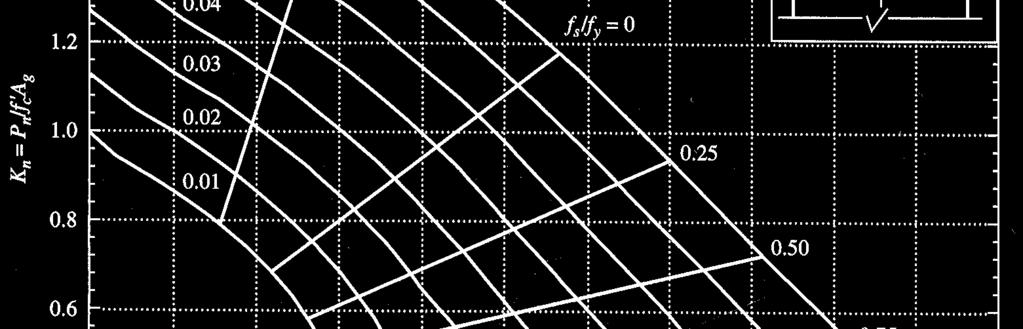
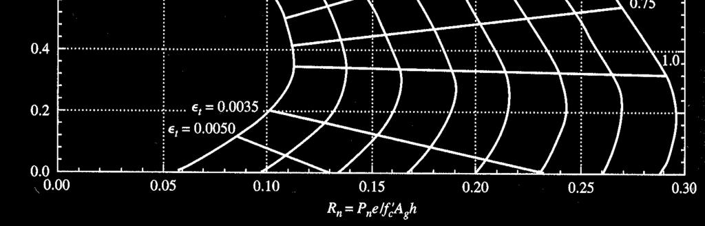
29 Example 10.7 Using the appropriate interation urves, determine the value o P n or the short tied olumn i e x =10 in (254 mm). Assume =4 ksi (26.7 MPa) and y =60 ksi (414 MPa). (76 mm) 3#32(2445 mm 2 ) 3#32(2445 mm 2 ) (305 mm) From Fig.10.15, Pn e A h g 0.24 is read P n 0.24 (356) (508) e (76 mm) A g h e h kips
30 0.0316
31 Shear in Columns mm., units in positive in ompression and all load, atored axial where tension, with axial ii) when aounting or lexure noted above or 8 4 (approximate) ompression, with axial ii) 1 where (aounting or lexure) (approximate) 6 1 load, without axial i) N N d b A N. V M d h N M M d b A N V M d V d b. d b M d V ρ V d b V u w g u u u u m w g u u u w w u u w w
32 Biaxial Bending
33 1 P P P P P ni where ni nx ny o 1 P Biaxial Bending Bresler Formula nx 1 P ny 1 P at an eentriity e at an eentriity e o the nominal axial load apaity o the setion when the load is plaed at a given eentriity along both axes the nominal axial load apaity o the setion when the load i splaed x the nominal axial load apaity o the setion when the load is plaed y the nominal axial load apaity o the setion when the load is plaed with a zero eentriity. It is usually taken as 0.85 A g A st y
34 Example 10.8 Determine the design apaity P ni o the short tied olumn subjeted to biaxial bending. Use =4 ksi (27.6 MPa), y =60 ksi (414 MPa), e x =16 in (406 mm) and e y =8 in (203 mm). (64 mm) Bending about X axis (8 #29) (64 mm) 254 (381 mm) (508) (635) (64 mm) e h 25 Pn e (Graph A8) A h P nx g kips


35 e/h=
36 Example 10.8 Determine the design apaity P ni o the short tied olumn subjeted to biaxial bending. Use =4 ksi (27.6 MPa), y =60 ksi (414 MPa), e x =16 in (406 mm) and e y =8 in (203 mm). (64 mm) (8 #29) (64 mm) 254 (381 mm) (508) (635) (64 mm) Bending about Y axis e h 15 Pn e (Graph A6 and A7) Ag h Pny 452.3kips 8
37 e/h=
38 e/h=
39 (8 #29) (64 mm) Example 10.8 Determine the design apaity P ni o the short tied olumn subjeted to biaxial bending. Use =4 ksi (27.6 MPa), y =60 ksi (414 MPa), e x =16 in (406 mm) and e y =8 in (203 mm). (64 mm) 254 (381 mm) (508) (635) (64 mm) Axial loading apaity or M P 0.85 o Ag y Ast kips Using Bresler's ormula Pni Pnx Pny Po P 253.5kips ni 0
Purpose of reinforcement P/2 P/2 P/2 P/2
 Department o Civil Engineering Purpose o reinorement Consider a simpl supported beam: P/2 P/2 3 1 2 P/2 P/2 3 2 1 1 Purpose o Reinorement Steel reinorement is primaril use beause o the nature o onrete
Chapter 6. Compression Reinforcement - Flexural Members
 Chapter 6. Compression Reinforement - Flexural Members If a beam ross setion is limite beause of arhitetural or other onsierations, it may happen that the onrete annot evelop the ompression fore require
Interaction Diagram Dumbbell Concrete Shear Wall Unsymmetrical Boundary Elements
 Interaction Diagram Dumbbell Concrete Shear Wall Unsymmetrical Boundary Elements Interaction Diagram - Dumbbell Concrete Shear Wall Unsymmetrical Boundary Elements Investigate the capacity for the irregular
Slenderness Effects for Concrete Columns in Sway Frame - Moment Magnification Method
 Slenderness Effets for Conrete Columns in Sway Frame - Moment Magnifiation Method Slender Conrete Column Design in Sway Frame Buildings Evaluate slenderness effet for olumns in a sway frame multistory
WRAP-AROUND GUSSET PLATES
 WRAP-AROUND GUSSET PLATES Where a horizontal brae is loated at a beam-to-olumn intersetion, the gusset plate must be ut out around the olumn as shown in Figure. These are alled wrap-around gusset plates.
TORSION By Prof. Ahmed Amer
 ORSION By Prof. Ahmed Amer orque wisting moments or torques are fores ating through distane so as to promote rotation. Example Using a wrenh to tighten a nut in a bolt. If the bolt, wrenh and fore are
Slenderness Effects for Concrete Columns in Sway Frame - Moment Magnification Method
 Slenderness Effets for Conrete Columns in Sway Frame - Moment Magnifiation Method Slender Conrete Column Design in Sway Frame Buildings Evaluate slenderness effet for olumns in a sway frame multistory
Reinforced Concrete Design
 Reinored Conrete Design Notation: a = depth o the eetive ompression blok in a onrete beam A g = gross area, equal to the total area ignoring any reinorement A s = area o steel reinorement in onrete beam
twenty steel construction: columns & tension members ARCHITECTURAL STRUCTURES: FORM, BEHAVIOR, AND DESIGN DR. ANNE NICHOLS FALL 2018 lecture
 ARCHITECTURAL STRUCTURES: FORM, BEHAVIOR, AND DESIGN DR. ANNE NICHOLS Cor-Ten Steel Sulpture By Rihard Serra Museum of Modern Art Fort Worth, TX (AISC - Steel Strutures of the Everyday) FALL 2018 leture
Uniaxial Concrete Material Behavior
 COMPUTERS AND STRUCTURES, INC., JULY 215 TECHNICAL NOTE MODIFIED DARWIN-PECKNOLD 2-D REINFORCED CONCRETE MATERIAL MODEL Overview This tehnial note desribes the Modified Darwin-Peknold reinfored onrete
Software Verification
 EC-4-004 Example-001 STEEL DESIGNERS MANUAL SEVENTH EDITION - DESIGN OF SIMPLY SUPPORTED COMPOSITE BEAM EXAMPLE DESCRIPTION Consider an internal seondary omposite beam of 1-m span between olumns and subjet
INFORMATION CONCERNING MATERIALS TO BE USED IN THE DESIGN
 TITLE 5 DESIGN CHAPTER 8 INFORMATION CONCERNING MATERIALS TO BE USED IN THE DESIGN Artile 38. Charateristis o steel or reinorements 38.1 General The harateristis o the steel used or the design desribed
Case Study in Reinforced Concrete adapted from Simplified Design of Concrete Structures, James Ambrose, 7 th ed.
 ARCH 631 Note Set 11 F015abn Case Study in Reinfored Conrete adapted from Simplified Design of Conrete Strutures, James Ambrose, 7 th ed. Building desription The building is a three-story offie building
fib Model Code 2020 Shear and punching provisions, needs for improvements with respect to new and existing structures
 fib Model Code 2020 Shear and punhing provisions, needs for improvements with respet to new and existing strutures Aurelio Muttoni Workshop fib Sao Paulo, 29.9.2017 Éole Polytehnique Fédérale de Lausanne,
Solid Mechanics Homework Answers
 Name: Date: Solid Mechanics Homework nswers Please show all of your work, including which equations you are using, and circle your final answer. Be sure to include the units in your answers. 1. The yield
Designing Reinforced Concrete Rectangular Columns for Biaxial Bending
 ENGINEERING DATA REORT NUMBER 57 Designing Reinforced Concrete Rectangular Columns for Biaxial Bending A SERVICE OF THE CONCRETE REINFORCING STEEL INSTITUTE 933 N. lum Grove Rd., Schaumburg, Illinois 60173-4758
MECHANICS OF MATERIALS
 CHAPER MECHANICS OF MAERIALS Ferdinand P. Beer E. Russell Johnston, Jr. John. DeWolf orsion Leture Notes: J. Walt Oler exas eh University 006 he MGraw-Hill Companies, In. All rights reserved. Contents
This Technical Note describes how the program checks column capacity or designs reinforced concrete columns when the ACI code is selected.
 COMPUTERS AND STRUCTURES, INC., BERKELEY, CALIFORNIA DECEMBER 2001 CONCRETE FRAME DESIGN ACI-318-99 Technical Note This Technical Note describes how the program checks column capacity or designs reinforced
Torsion. Torsion is a moment that twists/deforms a member about its longitudinal axis
 Mehanis of Solids I Torsion Torsional loads on Cirular Shafts Torsion is a moment that twists/deforms a member about its longitudinal axis 1 Shearing Stresses due to Torque o Net of the internal shearing
Civil Engineering Design (1) Design of Reinforced Concrete Columns 2006/7
 Design of Reinforced Concrete Columns 2006/7") Civil Engineering Design (1) Design of Reinforced Concrete Columns 2006/7 Dr. Colin Caprani, Chartered Engineer 1 Contents 1. Introduction... 3 1.1 Background... 3 1.2 Failure Modes... 5 1.3 Design Aspects...
Civil Engineering Design (1) Design of Reinforced Concrete Columns 2006/7 Dr. Colin Caprani, Chartered Engineer 1 Contents 1. Introduction... 3 1.1 Background... 3 1.2 Failure Modes... 5 1.3 Design Aspects...
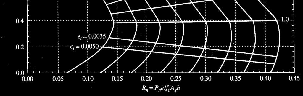
ε t increases from the compressioncontrolled Figure 9.15: Adjusted interaction diagram
 CHAPTER NINE COLUMNS 4 b. The modified axial strength in compression is reduced to account for accidental eccentricity. The magnitude of axial force evaluated in step (a) is multiplied by 0.80 in case
1/2. E c Part a The solution is identical for grade 40 and grade 60 reinforcement. P s f c n A s lbf. The steel carries 13.3 percent of the load
 1/2 3.1. A 16 20 in. column is made of the same concrete and reinforced with the same six No. 9 (No. 29) bars as the column in Examples 3.1 and 3.2, except t hat a steel with yield strength f y = 40 ksi
The Design of Fiber Reinforced Polymers for Structural Strengthening An Overview of ACI 440 Guidelines. Sarah Witt Fyfe Company November 7, 2008
 The Design o Fiber Reinored Polymers or Strutural Strengthening An Overview o ACI 440 Guidelines Sarah Witt Fye Company November 7, 2008 1 GUIDE FOR THE DESIGN AND CONSTRUCTION OF EXTERNALLY BONDED FRP
Strength of Materials
 Strength of Materials Session Pure Bending 04 Leture note : Praudianto, M.Eng. g{ V ä Ä tçw ÄtÇÇ Çz XÇz ÇÜ Çz Xwâvtà ÉÇ WÑtÜàÅÇà g{ V ä Ä tçw ÄtÇÇ Çz XÇz ÇÜ Çz Xwâvtà ÉÇ WÑtÜàÅÇà Pure Bending: Prisati
Dr. Hazim Dwairi 10/16/2008
 10/16/2008 Department o Civil Engineering Flexural Design o R.C. Beams Tpes (Modes) o Failure Tension Failure (Dutile Failure): Reinorement ields eore onrete ruses. Su a eam is alled under- reinored eam.
Chapter 1 Introduction- Concept of Stress
 hapter 1 Introduction- oncept of Stress INTRODUTION Review of Statics xial Stress earing Stress Torsional Stress 14 6 ending Stress W W L Introduction 1-1 Shear Stress W W Stress and Strain L y y τ xy
Static Failure (pg 206)
") Static Failure (pg 06) All material followed Hookeʹs law which states that strain is proportional to stress applied, until it exceed the proportional limits. It will reach and exceed the elastic limit
Static Failure (pg 06) All material followed Hookeʹs law which states that strain is proportional to stress applied, until it exceed the proportional limits. It will reach and exceed the elastic limit
Reinforced Concrete Design
 Reinfored Conrete Design Notation: a = depth of the effetive ompression blok in a onrete beam A = name for area A g = gross area, equal to the total area ignoring any reinforement A s = area of steel reinforement
and F NAME: ME rd Sample Final Exam PROBLEM 1 (25 points) Prob. 1 questions are all or nothing. PROBLEM 1A. (5 points)
 Prob. 1 questions are all or nothing. PROBLEM 1A. (5 points)") ME 270 3 rd Sample inal Exam PROBLEM 1 (25 points) Prob. 1 questions are all or nothing. PROBLEM 1A. (5 points) IND: In your own words, please state Newton s Laws: 1 st Law = 2 nd Law = 3 rd Law = PROBLEM
ME 270 3 rd Sample inal Exam PROBLEM 1 (25 points) Prob. 1 questions are all or nothing. PROBLEM 1A. (5 points) IND: In your own words, please state Newton s Laws: 1 st Law = 2 nd Law = 3 rd Law = PROBLEM
Lecture-03 Design of Reinforced Concrete Members for Flexure and Axial Loads
 Lecture-03 Design of Reinforced Concrete Members for Flexure and Axial Loads By: Prof. Dr. Qaisar Ali Civil Engineering Department UET Peshawar drqaisarali@uetpeshawar.edu.pk www.drqaisarali.com Prof.
Failure from static loading
 Failure from static loading Topics Quiz /1/07 Failures from static loading Reading Chapter 5 Homework HW 3 due /1 HW 4 due /8 What is Failure? Failure any change in a machine part which makes it unable
B U I L D I N G D E S I G N
 B U I L D I N G D E S I G N 10.1 DESIGN OF SLAB P R I O D E E P C H O W D H U R Y C E @ K 8. 0 1 7 6 9 4 4 1 8 3 DESIGN BY COEFFICIENT METHOD Loads: DL = 150 pc LL = 85 pc Material Properties: c = 3000
Wood Design. = theoretical allowed buckling stress
 Wood Design Notation: a = name for width dimension A = name for area A req d-adj = area required at allowable stress when shear is adjusted to inlude self weight b = width of a retangle = name for height
thirteen wood construction: column design ARCHITECTURAL STRUCTURES: FORM, BEHAVIOR, AND DESIGN DR. ANNE NICHOLS SUMMER 2017 lecture
 ARCHITECTURAL STRUCTURES: FORM, BEHAVIOR, AND DESIGN DR. ANNE NICHOLS SUMMER 2017 leture thirteen wood onstrution: olumn design Wood Columns 1 Compression Members (revisited) designed for strength & stresses
Design of AAC floor slabs according to EN 12602
 Design of AAC floor slabs aording to EN 160 Example 1: Floor slab with uniform load 1.1 Issue Design of a floor slab under a living room Materials Component with a ompressive strength lass AAC 4,5, densit
PROBLEM 7.1 SOLUTION. σ = 5.49 ksi. τ = ksi
 PROBLEM 7.1 For the given state of stress, determine the normal and shearing stresses exerted on the oblique face of the shaded triangular element shon. Use a method of analysis based on the equilibrium
Reinforced Concrete Design
 Reinfored Conrete Design Notation: a = depth of the effetive ompression blok in a onrete beam A = name for area Ag = gross area, equal to the total area ignoring any reinforement As = area of steel reinforement
Direct Design Method and Design Diagram. For Reinforced Concrete Columns and Shear walls
 Direct Design Method and Design Diagram For Reinforced Concrete Columns and Shear walls BY MAJID HOUSHIAR B.S., Isfahan University of Technology, 1988 M.S., University of Illinois at Chicago, Chicago,
According to the Ratio of Height to Least Lateral Dimension: (ACI Code and ACI Code ) < 22, when member is braced against sideways.
 < 22, when member is braced against sideways.") CHAPTER 5 COLUMN 5.1 INTRODUCTION Columns are structural elements used primarily to support compressive loads. All practical columns are members subjected not only to axial load but also to bendin moments,
CHAPTER 5 COLUMN 5.1 INTRODUCTION Columns are structural elements used primarily to support compressive loads. All practical columns are members subjected not only to axial load but also to bendin moments,
A.1. Member capacities A.2. Limit analysis A.2.1. Tributary weight.. 7. A.2.2. Calculations. 7. A.3. Direct design 13
 APPENDIX A APPENDIX A Due to its extension, the dissertation ould not inlude all the alulations and graphi explanantions whih, being not essential, are neessary to omplete the researh. This appendix inludes
Observations in Shear Wall Strength in Tall Buildings. Presented by StructurePoint at ACI Spring 2012 Convention in Dallas, Texas
 Observations in Shear Wall Strength in Tall Buildings Presented by StructurePoint at ACI Spring 2012 Convention in Dallas, Texas 1 Metropolitan Tower, New York City 68-story, 716 ft (218m) skyscraper Reinforced
Reinforced Concrete Design
 Reinfored Conrete Design Notation: a = depth of the effetive ompression blok in a onrete beam A = name for area A g = gross area, equal to the total area ignoring any reinforement A s = area of steel reinforement
Strength of Material. Shear Strain. Dr. Attaullah Shah
 Strength of Material Shear Strain Dr. Attaullah Shah Shear Strain TRIAXIAL DEFORMATION Poisson's Ratio Relationship Between E, G, and ν BIAXIAL DEFORMATION Bulk Modulus of Elasticity or Modulus of Volume
Design of Reinforced Concrete Beam for Shear
 Lecture 06 Design of Reinforced Concrete Beam for Shear By: Prof Dr. Qaisar Ali Civil Engineering Department UET Peshawar drqaisarali@uetpeshawar.edu.pk 1 Topics Addressed Shear Stresses in Rectangular
Masonry Beams. Ultimate Limit States: Flexure and Shear
 Masonry Beams 4:30 PM 6:30 PM Bennett Banting Ultimate Limit States: Flexure and Shear Leture Outline 1. Overview (5) 2. Design for Flexure a) Tension Reinforement (40) b) Compression Reinforement (20)
Compression Members Local Buckling and Section Classification
 Compression Memers Loal Bukling and Setion Classifiation Summary: Strutural setions may e onsidered as an assemly of individual plate elements. Plate elements may e internal (e.g. the wes of open eams
Mechanical Properties of Materials
 Mechanical Properties of Materials Strains Material Model Stresses Learning objectives Understand the qualitative and quantitative description of mechanical properties of materials. Learn the logic of
Biaxial Analysis of General Shaped Base Plates
 Biaxial Analysis of General Shaped Base Plates R. GONZALO ORELLANA 1 Summary: A linear model is used for the contact stresses calculation between a steel base plate and a concrete foundation. It is also
ACI Fall Convention 2010 Pittsburgh, PA ARGENTINA DOCUMENT
 ACI Fall Convention 2010 Pittsburgh, PA October 24-28, 2010 ARGENTINA DOCUMENT Developed for INTI-CIRSOC by Eng. Daniel Ortega from INTI-CIRSOC Eng. Victorio Hernández Balat from Quasdam Ingeniería COMMENTARIES
[5] Stress and Strain
![[5] Stress and Strain](/thumbs/95/123344550.jpg "[5] Stress and Strain") [5] Stress and Strain Page 1 of 34 [5] Stress and Strain [5.1] Internal Stress of Solids [5.2] Design of Simple Connections (will not be covered in class) [5.3] Deformation and Strain [5.4] Hooke s Law
[5] Stress and Strain Page 1 of 34 [5] Stress and Strain [5.1] Internal Stress of Solids [5.2] Design of Simple Connections (will not be covered in class) [5.3] Deformation and Strain [5.4] Hooke s Law
Flexural Strength Design of RC Beams with Consideration of Strain Gradient Effect
 World Aademy of Siene, Engineering and Tehnology Vol:8, No:6, 04 Flexural Strength Design of RC Beams with Consideration of Strain Gradient Effet Mantai Chen, Johnny Ching Ming Ho International Siene Index,
Determine the resultant internal loadings acting on the cross section at C of the beam shown in Fig. 1 4a.
 E X M P L E 1.1 Determine the resultant internal loadings acting on the cross section at of the beam shown in Fig. 1 a. 70 N/m m 6 m Fig. 1 Support Reactions. This problem can be solved in the most direct
[8] Bending and Shear Loading of Beams
![[8] Bending and Shear Loading of Beams](/thumbs/92/110949676.jpg "[8] Bending and Shear Loading of Beams") [8] Bending and Shear Loading of Beams Page 1 of 28 [8] Bending and Shear Loading of Beams [8.1] Bending of Beams (will not be covered in class) [8.2] Bending Strain and Stress [8.3] Shear in Straight
[8] Bending and Shear Loading of Beams Page 1 of 28 [8] Bending and Shear Loading of Beams [8.1] Bending of Beams (will not be covered in class) [8.2] Bending Strain and Stress [8.3] Shear in Straight
4.MECHANICAL PROPERTIES OF MATERIALS
 4.MECHANICAL PROPERTIES OF MATERIALS The diagram representing the relation between stress and strain in a given material is an important characteristic of the material. To obtain the stress-strain diagram
PURE BENDING. If a simply supported beam carries two point loads of 10 kn as shown in the following figure, pure bending occurs at segment BC.
 BENDING STRESS The effect of a bending moment applied to a cross-section of a beam is to induce a state of stress across that section. These stresses are known as bending stresses and they act normally
Two-Way Flat Slab (Concrete Floor with Drop Panels) System Analysis and Design
 System Analysis and Design") Two-Way Flat Slab (Conrete Floor with Drop Panels) System Analysis and Design Two-Way Flat Slab (Conrete Floor with Drop Panels) System Analysis and Design Design the onrete floor slab system shown below
Two-Way Flat Slab (Conrete Floor with Drop Panels) System Analysis and Design Two-Way Flat Slab (Conrete Floor with Drop Panels) System Analysis and Design Design the onrete floor slab system shown below
Stress Transformation Equations: u = +135 (Fig. a) s x = 80 MPa s y = 0 t xy = 45 MPa. we obtain, cos u + t xy sin 2u. s x = s x + s y.
 s x = 80 MPa s y = 0 t xy = 45 MPa. we obtain, cos u + t xy sin 2u. s x = s x + s y.") 014 Pearson Education, Inc., Upper Saddle River, NJ. All rights reserved. This material is protected under all copyright laws as they currently 9 7. Determine the normal stress and shear stress acting
014 Pearson Education, Inc., Upper Saddle River, NJ. All rights reserved. This material is protected under all copyright laws as they currently 9 7. Determine the normal stress and shear stress acting
D : SOLID MECHANICS. Q. 1 Q. 9 carry one mark each. Q.1 Find the force (in kn) in the member BH of the truss shown.
 in the member BH of the truss shown.") D : SOLID MECHANICS Q. 1 Q. 9 carry one mark each. Q.1 Find the force (in kn) in the member BH of the truss shown. Q.2 Consider the forces of magnitude F acting on the sides of the regular hexagon having
D : SOLID MECHANICS Q. 1 Q. 9 carry one mark each. Q.1 Find the force (in kn) in the member BH of the truss shown. Q.2 Consider the forces of magnitude F acting on the sides of the regular hexagon having
CONNECTION DESIGN. Connections must be designed at the strength limit state
 CONNECTION DESIGN Connections must be designed at the strength limit state Average of the factored force effect at the connection and the force effect in the member at the same point At least 75% of the
Please review the following statement: I certify that I have not given unauthorized aid nor have I received aid in the completion of this exam.
 Please review the followg statement: I certify that I have not given unauthorized aid nor have I received aid the completion of this eam. Signature: INSTRUCTIONS Beg each problem the space provided on
The casing is subjected to the following:
 16.50 Leture 13 Subjet: Roket asing design; Strutural modeling Thus far all our modeling has dealt with the fluid mehanis and thermodynamis of rokets. This is appropriate beause it is these features that
Stress Analysis Lecture 3 ME 276 Spring Dr./ Ahmed Mohamed Nagib Elmekawy
 Stress Analysis Lecture 3 ME 276 Spring 2017-2018 Dr./ Ahmed Mohamed Nagib Elmekawy Axial Stress 2 Beam under the action of two tensile forces 3 Beam under the action of two tensile forces 4 Shear Stress
Software Verification
 Sotare Veriiation EXAMPLE NZS 3101-06 RC-BM-001 Flexural and Shear Beam Deign PROBLEM DESCRIPTION The purpoe o thi example i to veriy lab lexural deign in. The load level i adjuted or the ae orreponding
eighteen steel construction: column design ELEMENTS OF ARCHITECTURAL STRUCTURES: FORM, BEHAVIOR, AND DESIGN DR. ANNE NICHOLS SPRING 2019 lecture
 ELEMENTS OF ARCHITECTURAL STRUCTURES: FORM, BEHAVIOR, AND DESIGN DR. ANNE NICHOLS SPRING 2019 letue eighteen steel onstution: olumn design Co-Ten Steel Sulptue By Rihad Sea Museum of Moden At Fot Woth,
Shear-Friction Strength of RC Walls with 550 MPa Bars
 Proeedings of the Tenth Paifi Conferene on Earthquake Engineering Building an Earthquake-Resilient Paifi 6-8 November 215, Sydney, Australia Shear-Frition Strength of RC Walls with 55 MPa Bars Jang-woon
Reports RESEARCH REPORT RP00-3 RESEARCH REPORT RP01-1 OCTOBER REVISION 2006 REVISION
 research report A AISI Design Sponsored Approach Resear for ch Complex Reports AISI Sponsored Stiffeners Research Reports RESEARCH REPORT RP00-3 RP01-1 RESEARCH REPORT RP01-1 OCTOBER 2001 2000 REVISION
Virtual Work for Frames. Virtual Work for Frames. Virtual Work for Frames. Virtual Work for Frames. Virtual Work for Frames. Virtual Work for Frames
 IL 32 /9 ppling the virtual work equations to a frame struture is as simple as separating the frame into a series of beams and summing the virtual work for eah setion. In addition, when evaluating the
Design of Reinforced Concrete Beam for Shear
 Lecture 06 Design of Reinforced Concrete Beam for Shear By: Civil Engineering Department UET Peshawar drqaisarali@uetpeshawar.edu.pk Topics Addressed Shear Stresses in Rectangular Beams Diagonal Tension
Introduction. ENCE 710 Design of Steel Structures IV. COMPOSITE STEEL-CONCRET CONSTRUCTION. Effective Width. Composite Action
 ENCE 710 Design of Steel Strutures V. COMPOSTE STEEL-CONCRET CONSTRUCTON C. C. Fu, Ph.D., P.E. Civil and Environmental Engineering Department University of Maryland ntrodution Following subjets are overed:
twenty one concrete construction: materials & beams ELEMENTS OF ARCHITECTURAL STRUCTURES: FORM, BEHAVIOR, AND DESIGN DR. ANNE NICHOLS SPRING 2014
 ELEMENTS OF ARCHITECTURAL STRUCTURES: FORM, BEHAVIOR, AND DESIGN DR. ANNE NICHOLS SPRING 2014 lecture twenty one concrete construction: http:// nisee.berkeley.edu/godden materials & beams Concrete Beams
Problem d d d B C E D. 0.8d. Additional lecturebook examples 29 ME 323
 Problem 9.1 Two beam segments, AC and CD, are connected together at C by a frictionless pin. Segment CD is cantilevered from a rigid support at D, and segment AC has a roller support at A. a) Determine
MECHANICS OF MATERIALS. Prepared by Engr. John Paul Timola
 MECHANICS OF MATERIALS Prepared by Engr. John Paul Timola Mechanics of materials branch of mechanics that studies the internal effects of stress and strain in a solid body. stress is associated with the
ME 202 STRENGTH OF MATERIALS SPRING 2014 HOMEWORK 4 SOLUTIONS
 ÇANKAYA UNIVERSITY MECHANICAL ENGINEERING DEPARTMENT ME 202 STRENGTH OF MATERIALS SPRING 2014 Due Date: 1 ST Lecture Hour of Week 12 (02 May 2014) Quiz Date: 3 rd Lecture Hour of Week 12 (08 May 2014)
Purpose of this Guide: To thoroughly prepare students for the exact types of problems that will be on Exam 3.
 ES230 STRENGTH OF MTERILS Exam 3 Study Guide Exam 3: Wednesday, March 8 th in-class Updated 3/3/17 Purpose of this Guide: To thoroughly prepare students for the exact types of problems that will be on
DESIGN OF BEAMS AND SHAFTS
 DESIGN OF EAMS AND SHAFTS! asis for eam Design! Stress Variations Throughout a Prismatic eam! Design of pristmatic beams! Steel beams! Wooden beams! Design of Shaft! ombined bending! Torsion 1 asis for
Software Verification
 AISC-360-10 Example 001 COMPOSITE GIRDER DESIGN EXAMPLE DESCRIPTION A typial bay of a omposite floor system is illstrated below. Selet an appropriate ASTM A992 W-shaped beam and determine the reqired nmber
Design of a Multi-Storied RC Building
 Design of a Multi-Storied RC Building 16 14 14 3 C 1 B 1 C 2 B 2 C 3 B 3 C 4 13 B 15 (S 1 ) B 16 (S 2 ) B 17 (S 3 ) B 18 7 B 4 B 5 B 6 B 7 C 5 C 6 C 7 C 8 C 9 7 B 20 B 22 14 B 19 (S 4 ) C 10 C 11 B 23
Flexure: Behavior and Nominal Strength of Beam Sections
 4 5000 4000 (increased d ) (increased f (increased A s or f y ) c or b) Flexure: Behavior and Nominal Strength of Beam Sections Moment (kip-in.) 3000 2000 1000 0 0 (basic) (A s 0.5A s ) 0.0005 0.001 0.0015
Lecture-04 Design of RC Members for Shear and Torsion
 Lecture-04 Design of RC Members for Shear and Torsion By: Prof. Dr. Qaisar Ali Civil Engineering Department UET Peshawar drqaisarali@uetpeshawar.edu.pk www.drqaisarali.com 1 Topics Addressed Design of
Example 4.1 [Uni-axial Column Design] Solution. Step 1- Material Step 2-Determine the normalized axial and bending moment value
![Example 4.1 [Uni-axial Column Design] Solution. Step 1- Material Step 2-Determine the normalized axial and bending moment value](/thumbs/75/72436916.jpg "Example 4.1 [Uni-axial Column Design] Solution. Step 1- Material Step 2-Determine the normalized axial and bending moment value") Example 4.1 [Uni-axial Column Design] 1. Design the braced short column to sustain a design load of 1100 KN and a design moment of 160KNm which include all other effects.use C5/30 and S460 class 1 works
Example 4.1 [Uni-axial Column Design] 1. Design the braced short column to sustain a design load of 1100 KN and a design moment of 160KNm which include all other effects.use C5/30 and S460 class 1 works
Reinforced concrete structures II. 4.5 Column Design
 4.5 Column Design A non-sway column AB of 300*450 cross-section resists at ultimate limit state, an axial load of 700 KN and end moment of 90 KNM and 0 KNM in the X direction,60 KNM and 27 KNM in the Y
BEAMS: SHEARING STRESS
 LECTURE Third Edition BEAMS: SHEARNG STRESS A. J. Clark Shool of Engineering Department of Civil and Environmental Engineering 14 Chapter 6.1 6.4 b Dr. brahim A. Assakkaf SPRNG 200 ENES 220 Mehanis of
Software Verification
 Sotware Veriiation EXAMPLE CSA A23.3-04 RC-BM-00 Flexural and Shear Beam Deign PROBLEM DESCRIPTION The purpoe o thi example i to veri lab lexural deign in. The load level i adjuted or the ae orreponding
MECHANICS OF MATERIALS Sample Problem 4.2
 Sample Problem 4. SOLUTON: Based on the cross section geometry, calculate the location of the section centroid and moment of inertia. ya ( + Y Ad ) A A cast-iron machine part is acted upon by a kn-m couple.
Column Design. Columns Axial Load and Bending
 Column Design MORGAN STATE UNIVERSITY SCHOOL OF ARCHITECTURE AND PLANNING LECTURE VI Dr. Jason E. Charalambides = = Columns Axial Load and Bending We tend to have this image of columns that we envision
CONSULTING Engineering Calculation Sheet. Job Title Member Design - Reinforced Concrete Column BS8110
 E N G I N E E R S Consulting Engineers jxxx 1 Job Title Member Design - Reinforced Concrete Column Effects From Structural Analysis Axial force, N (tension-ve and comp +ve) (ensure >= 0) 8000kN OK Major
BEHAVIOR OF SQUARE CONCRETE-FILLED TUBULAR COLUMNS UNDER ECCENTRIC COMPRESSION WITH DOUBLE CURVATURE DEFLECTION
 Otober 2-7, 28, Beijing, China BEHAVIOR OF SQARE CONCRETE-FILLED TBLAR COLNS NDER ECCENTRIC COPRESSION WITH DOBLE CRVATRE DEFLECTION T. Fujinaga, H. Doi 2 and Y.P. Sun 3 Assoiate Professor, Researh Center
Rectangular Filament-Wound GFRP Tubes Filled with Concrete under Flexural. and Axial Loading: Analytical Modeling ABSTRACT
 Retangular Filament-Wound GFRP Tubes Filled with Conrete under Flexural and Axial Loading: Analytial Modeling Amir Fam 1, Siddhwartha Mandal 2, and Sami Rizkalla 3 ABSTRACT This paper presents an analytial
If the solution does not follow a logical thought process, it will be assumed in error.
 Please indicate your group number (If applicable) Circle Your Instructor s Name and Section: MWF 8:30-9:20 AM Prof. Kai Ming Li MWF 2:30-3:20 PM Prof. Fabio Semperlotti MWF 9:30-10:20 AM Prof. Jim Jones
Mechanics of Materials CIVL 3322 / MECH 3322
 Mechanics of Materials CIVL 3322 / MECH 3322 2 3 4 5 6 7 8 9 10 A Quiz 11 A Quiz 12 A Quiz 13 A Quiz 14 A Quiz 15 A Quiz 16 In Statics, we spent most of our time looking at reactions at supports Two variations
Mechanics of Solids. Mechanics Of Solids. Suraj kr. Ray Department of Civil Engineering
 Mechanics Of Solids Suraj kr. Ray (surajjj2445@gmail.com) Department of Civil Engineering 1 Mechanics of Solids is a branch of applied mechanics that deals with the behaviour of solid bodies subjected
Torsion of Shafts Learning objectives
 Torsion of Shafts Shafts are structural members with length significantly greater than the largest cross-sectional dimension used in transmitting torque from one plane to another. Learning objectives Understand
The science of elasticity
 The science of elasticity In 1676 Hooke realized that 1.Every kind of solid changes shape when a mechanical force acts on it. 2.It is this change of shape which enables the solid to supply the reaction
Bending and Shear in Beams
 Bending and Shear in Beams Lecture 3 5 th October 017 Contents Lecture 3 What reinforcement is needed to resist M Ed? Bending/ Flexure Section analysis, singly and doubly reinforced Tension reinforcement,
Samantha Ramirez, MSE. Stress. The intensity of the internal force acting on a specific plane (area) passing through a point. F 2
 passing through a point. F 2") Samantha Ramirez, MSE Stress The intensity of the internal force acting on a specific plane (area) passing through a point. Δ ΔA Δ z Δ 1 2 ΔA Δ x Δ y ΔA is an infinitesimal size area with a uniform force
Samantha Ramirez, MSE Stress The intensity of the internal force acting on a specific plane (area) passing through a point. Δ ΔA Δ z Δ 1 2 ΔA Δ x Δ y ΔA is an infinitesimal size area with a uniform force
 mportant nstructions to examiners: ) The answers should be examined by key words and not as word-to-word as given in the model answer scheme. ) The model answer and the answer written by candidate may
Chapter. Materials. 1.1 Notations Used in This Chapter
 Chapter 1 Materials 1.1 Notations Used in This Chapter A Area of concrete cross-section C s Constant depending on the type of curing C t Creep coefficient (C t = ε sp /ε i ) C u Ultimate creep coefficient
M. Vable Mechanics of Materials: Chapter 5. Torsion of Shafts
 Torsion of Shafts Shafts are structural members with length significantly greater than the largest cross-sectional dimension used in transmitting torque from one plane to another. Learning objectives Understand
STRENGTH OF MATERIALS-I. Unit-1. Simple stresses and strains
 STRENGTH OF MATERIALS-I Unit-1 Simple stresses and strains 1. What is the Principle of surveying 2. Define Magnetic, True & Arbitrary Meridians. 3. Mention different types of chains 4. Differentiate between
Seismic Pushover Analysis Using AASHTO Guide Specifications for LRFD Seismic Bridge Design
 Seismic Pushover Analysis Using AASHTO Guide Specifications for LRFD Seismic Bridge Design Elmer E. Marx, Alaska Department of Transportation and Public Facilities Michael Keever, California Department