Twin City Fan Companies. Fan System Effects
|
|
|
- Malcolm Montgomery
- 5 years ago
- Views:
Transcription


1 Fan System Effects
2 Outline Fan Testing Review Definition of System Effect Old ASHRAE guidelines AMCA 201 System Effect Factors Examples Demonstration Aimed at the fan system designer There are two goals: Avoid poor fan system configurations When optimum conditions cannot be met, use the system effect factors to estimate any losses during system design

3 AMCA Publication Defines standard methods of testing fans for rating purposes

4 Fan Ratings Fan ratings are established using AMCA 210 test codes that are close to ideal conditions Straight, uniform flow directed only in the axial direction entering the fan Discharge duct long enough to allow flow to fully develop Uniform airflow conditions ensure consistency and reproducibility of test results AND permit the fan to develop its maximum performance.
5 Inlet Velocity Profile
6 Discharge Velocity Profile

7 Typical AMCA 210 Test Set-up
8 What is System Effect? Fans in actual systems are often less than ideal When an installation produces airflow that is not uniform, the fan s performance will be measurably reduced. The difference in performance for the same fan tested in both conditions is the System Effect In other words, anything that is placed in close proximity before or after the fan that effects the catalogued performance. System Effect Factors (SEF): A factor used to correct for system induced installation effects
9 Why System Effect is Important If not accounted for, must accept deficient performance, or... Speed up the fan (if possible) May require more energy to meet performance May exceed motor horsepower limit Many cause excessive noise Many cause excessive vibration
10 Two Components of System Design Calculate flow resistance losses for each component in the system Select and position fan to avoid system effect loss If loss cannot be avoided, estimate loss and select fan for higher pressure
11 Ductwork Example System Effect Controlled by Inlet and Outlet Conditions System Resistance
 There is a system effect")
12 Causes of Non-Performing Systems System resistance has been miscalculated Fan not properly selected Defective fan (or fan rating) There is a system effect loss
13 Fan Manufacturer s Responsibility Provide accurate fan performance ratings Provide a fan built within tolerance so that it is capable of meeting its rating Manufacturer is not responsible for system resistance or system effect
14 In the past ASHRAE published guidelines for avoiding losses in fan performance (~1950s) Labeled as Right or Wrong only qualitative
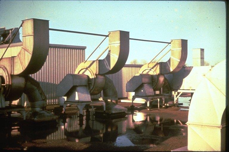
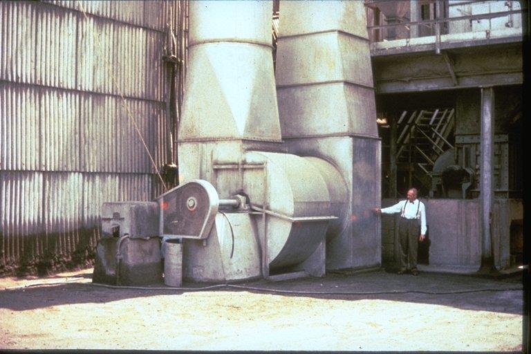
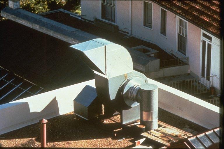
15 Inlet Connections
16 Outlet Connections
17 Outlet Connections
18 What was missing? Only guidelines to avoid losses No way to quantify losses

19 AMCA Publication 201:2002 Generated in 1973 from ASHRAE funded research. Quantifies duct system design effect on performance. Known as the bible of system effects.
20 Design pressure Normal System Performance 1 Calculated duct system curve Fan curve Design volume
21 Design pressure System effect at actual flow volume Deficient Performance With System Effect Operating point is at point 3 Operating point is not on fan curve! Calculated duct system with no allowance for system effect Original fan curve Design volume Deficient volume
22 Design pressure Correcting For System Effect System effect at actual flow volume Actual duct system with system effect 2 Calculated duct system with no allowance for system effect 4 System effect loss at design volume 1 3 New fan curve Original fan curve Design volume Deficient volume
23 With System Effects Added The fan will be selected for the higher pressure (no need to speed up) The motor will be selected to include the anticipated loss
24 Causes of Losses Inlet losses are caused by: Unequal loading of the fan blades (eccentric flow) Improper fan blade attack angle Turbulence which disrupts the flow Outlet losses are caused by: Loss of conversion of local high velocity into pressure
25 Inlet vs. Outlet Losses Inlet induced losses tend to be higher than outlet losses Losses induced on the inlet can often exceed 20% Losses as high as 50% have been reported
26 How Losses are Quantified AMCA 201 publishes data for a variety of configurations Most identify a Loss Curve which is based on the configuration and identified by a letter Most also need the air velocity as a parameter
27 System Effect Curves Curve T Add 0.55 to Static Pressure 4000 FPM
28 Outlet System Effects In addition to the flow velocity, may need to know: effective duct length blast area for centrifugal fans
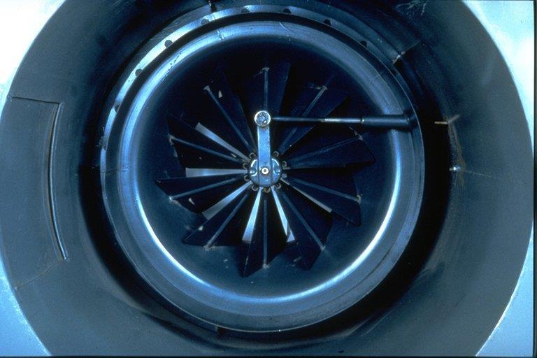
29 System Effect Curves for Outlet Ducts Axial Fans
30 Fan Outlet Velocity Profile - Centrifugal If duct is rectangular with side dimensions a x b, the equivalent duct diameter is equal to (4*a*b/π)^0.5
31 System Effect Curves for Outlet Ducts - Centrifugal Fans
32 Outlet Duct Elbows - Centrifugal Fans

33 System Effect Curves for SWSI Fans
34 System Effect Curves for Outlet Duct Elbows - Axial Fans
35 System Effect Curves for Inlet Duct Elbows - Axial Fans

36 Percentage of Unobstructed Inlet Area
37 Fans and Plenum L System Effect Curve 0.75 x Inlet Dia V-W 0.50 x Inlet Dia U 0.40 x Inlet Dia T 0.30 x Inlet Dia S
38 Elbows Change the Velocity Profile

39 Right Angle Turns At Fan Inlet Length of Duct R Inlet with 3-piece elbow Inlet with rectangular inlet Duct Inlet with special designed inlet box All methods will induce some system effect loss. Some methods are better than others

40 R / D S y s t e m E f f e c t C u r v e s N o D u c t 2 D D u c t 5 D D u c t - - N P R - S R / D S y s t e m E f f e c t C u r v e s N o D u c t 2 D D u c t 5 D D u c t 0. 5 O Q S Q R - S T - U 1. 0 R S - T U - V 2. 0 R - S T U - V 3. 0 S T - U V R / D System Effect - Round Inlet Ducts S y s t e m E f f e c t C u r v e s N o D u c t 2 D D u c t 5 D D u c t 0. 5 P - Q R - S T Q - R S U 1. 0 R S - T U - V 2. 0 R - S T U - V 3. 0 S - T U V - D D D L e n g t h o f D u c t L e n g t h o f D u c t L e n g t h o f D u c t R R R 2 piece mitered round section 3 piece mitered round section 4 or more piece mitered round section

41 System Effect Curves System Effect - Square Elbow and Turning Vanes System Effect Curves System Effect Curves R/D No Duct 2D Duct 5D Duct 0.5 O Q S 0.75 P R S-T 1.0 R S-T U-V 2.0 S T-U V R/D No Duct 2D Duct 5D Duct 0.5 S T-U V 1.0 T U-V W 2.0 V V-W W-X R/D No Duct 2D Duct 5D Duct 0.5 S T-U V 1.0 T U-V W 2.0 V V-W W-X H Square H Square H Square Len gth of Du ct Length of Duct Length of Duct R R R Square elbow - no turning vanes Square elbow - long turning vanes Square elbow - short turning vanes
42 Forced Inlet Vortex (Inlet Spin or Swirl) Pre-Rotating Inlet Swirl Counter-Rotating Inlet Swirl
43 Corrections for Inlet Swirl
44
45 Normalized Pressure -Volume Curve Note that this is similar to a variable system effect. A new curve is generated at each vane setting
46 Pressure Drop Multipliers for Volume Control Dampers on a Fan Outlet
47 Measured Inlet Sound Power Vaneaxial Fan System Effect Blade Pass Hz Fan Only 2 PC Elbow on Inlet 2 PC Elbow 3 De
48 System Effect Factors are Real When designing your fan/system, do everything possible to avoid a system effect for efficient use of energy When conditions leading to system effect cannot be avoided, add the calculated loss to the fan pressure requirement at the system design stage

49
50
51
52
53
54
55

56 Flow Tube Example

57 Reference Materials AMCA Publication 201:2002, Fans and Systems Twin City Fan ED-100, Fan Performance Troubleshooting Guide
HVAC Clinic. Duct Design
 HVAC Clinic Duct Design Table Of Contents Introduction... 3 Fundamentals Of Duct Design... 3 Pressure Changes In A System... 8 Example 1... 13 Duct Design Methods... 15 Example 2... 15 Introduction The
BNA Series. PLENUM FAN with Backward Wheels
 BNA Series PLENUM FAN with Backward Wheels BNA Series BNA Series Plenum Fans Backward wheels Kruger Plenum Fans are designed for air handling applications where the fan operates unhoused within a plenum.
The diagram below. to the by the. outlet into. calculation. Since TRANSMISSION VIA STRUCTURE. Vibration Via Supports Duct Breakout
 NOISE CONTROL IN VENTILATING SYSTEMS INTRODUCTION The diagram below shows the various noise sources and transmission paths of plant rooms and ventilation systems. For the ventilation system this can be
Cdesign must consider (1) space availability, (2) space air
 space availability, (2) space air") ASHRAE Fundimental CHAPChTER 32 DUCT DESIGN Bernoulli Equation.... 32.1 Head and Pressure.... 32.2 SYSTEM ANALYSIS.... 32.2 Pressure Changes in System.... 32.6 FLUID RESISTANCE.... 32.7 Friction Losses....
ASHRAE Fundimental CHAPChTER 32 DUCT DESIGN Bernoulli Equation.... 32.1 Head and Pressure.... 32.2 SYSTEM ANALYSIS.... 32.2 Pressure Changes in System.... 32.6 FLUID RESISTANCE.... 32.7 Friction Losses....
Sound Rating of Ducted Air Moving and Conditioning Equipment
 AHRI Standard 260 (I-P) 2017 Standard for Sound Rating of Ducted Air Moving and Conditioning Equipment IMPORTANT SAFETY DISCLAIMER AHRI does not set safety standards and does not certify or guarantee the
Treatment of Tonal Sound in the Development of Fan Sound Ratings
 ENGINEERING PAPER 55-08 Treatment of Tonal Sound in the Development of Fan Sound Ratings Tim Mathson Manager - CVI Engineering Greenheck Fan Corp. AMCA International Engineering Conference Las Vegas, NV,
AN INVESTIGATION OF ALTERNATIVE METHODS FOR MEASURING STATIC PRESSURE OF UNITARY AIR CONDITIONERS AND HEAT PUMPS
 AN INVESTIGATION OF ALTERNATIVE METHODS FOR MEASURING STATIC PRESSURE OF UNITARY AIR CONDITIONERS AND HEAT PUMPS A Thesis by GRANT BENSON WHEELER Submitted to the Office of Graduate Studies of Texas A&M
EUROVENT 8/12 SOUND TEST METHOD FOR DUCTED FAN COIL UNITS. FCP 2008 testing procedures FCP acoustical test method pag. 1
 EUROVENT 8/12 SOUND TEST METHOD FOR DUCTED FAN COIL UNITS FCP 2008 testing procedures FCP acoustical test method pag. 1 CONTENTS 1 - PURPOSE... 3 2 - NORMATIVE REFERENCES... 3 3 - DEFINITIONS... 3 3.1
 Ventilation 5 Fans Vladimír Zmrhal (room no. 814) http://users.fs.cvut.cz/~zmrhavla/index.htm Dpt. Of Environmental Engineering 1 Introduction Fans air pump that creates a pressure difference and causes
FAN TERMINOLOGY. t = 1.2 kg/m 3 (Standard air density at 20 C and 1013mb. V = duct air velocity, m/s.
 +7 (0)1 55 1077 +7 (0)1 55 797 FAN TERMINOLOGY These notes are designed to explain some of the terms that are used in describing the characteristics of fans and the relationship between the fan performance
Cdesign must consider (1) space availability, (2) space air diffusion,
 space availability, (2) space air diffusion,") Related Commercial Resources CHAPTER 35 DUCT DESIGN BERNOULLI EQUATION... 35.1 Head and Pressure... 35.2 SYSTEM ANALYSIS... 35.2 Pressure Changes in System... 35.5 FLUID RESISTANCE... 35.6 Friction Losses...
Related Commercial Resources CHAPTER 35 DUCT DESIGN BERNOULLI EQUATION... 35.1 Head and Pressure... 35.2 SYSTEM ANALYSIS... 35.2 Pressure Changes in System... 35.5 FLUID RESISTANCE... 35.6 Friction Losses...
Technical Explanation for Axial Fans
 CSM_Axial_TG_E Introduction What Is an Axial? Axial fans are used for stable cooling in many different applications and locations. If the temperature of a device increases, the lives of its internal parts
FAN ENGINEERING. Field Testing of Fans. Twin City Fan FE-900. Introduction. Testing Equipment. Testing Standards. Prior to Testing
 FAN ENGINEERING Twin City Fan Information and Recommendations for the Engineer Introduction There are many reasons why a fan test may be performed. AMCA publications cover three categories of tests. 1.
Applied Fluid Mechanics
 Applied Fluid Mechanics 1. The Nature of Fluid and the Study of Fluid Mechanics 2. Viscosity of Fluid 3. Pressure Measurement 4. Forces Due to Static Fluid 5. Buoyancy and Stability 6. Flow of Fluid and
Duct Design and Air Distribution Systems
 Duct Design and Air Distribution Systems Introduction The chief requirements of an air conditioning duct system are: It should convey specified rates of air flow to prescribed locations It should be economical
Non- Iterative Technique for Balancing an. Air Distribution System
 Non- Iterative Technique for Balancing an Air Distribution System Mauro Small Thesis presented to the Faculty of Virginia Polytechnic Institute and State University in partial fulfillment of the requirements
Operation and sound power characteristics of cooling fans in surrounding structures
 20 Operation and sound power characteristics of cooling fans in surrounding structures Johannes Hyrynen, VTT Industrial Systems P.O.Box 1307 33101Tampere Finland This paper gives a view of means to design
Lecture 22. Mechanical Energy Balance
 Lecture 22 Mechanical Energy Balance Contents Exercise 1 Exercise 2 Exercise 3 Key Words: Fluid flow, Macroscopic Balance, Frictional Losses, Turbulent Flow Exercise 1 It is proposed to install a fan to
Ecolibrium. All natural. A new style for supermarkets? THE OFFICIAL JOURNAL OF AIRAH AUGUST 2017 VOLUME 16.7 RRP $14.95
 THE OFFICIAL JOURNAL OF AIRAH Ecolibrium AUGUST 2017 VOLUME 16.7 RRP $14.95 PRINT POST APPROVAL NUMBER PP352532/00001 All natural A new style for supermarkets? ESTABLISHED 1947 Celebrating 70 years as
Understanding & Reducing Air System Noise
 AMCA International Understanding & Reducing Air System Noise John D. Sofra Market Manager - Airflow Attenuation, Industrial, Environmental Markets Kinetics Noise Control, Inc., Dublin, Ohio jsofra@kineticsnoise.com
The Curious Definition Of Fan Static Pressure PART-2
 The Curious Definition Of Fan Static Pressure PART-2 Mat Ansari PE Figure-3 shows AMCA test type designations. (Luckily someone at AMCA had binary code in mind. If 0 is no duct and 1 is ducted, the 00,
Duct Design. Lecturer: 王啟川, PhD Fellow ASME, Fellow ASHRAE Tel: ext
 Duct Design Lecturer: 王啟川, PhD Fellow ASME, Fellow ASHRAE Tel: 3-5712121 ext. 55105 E-mail:ccwang@mail.nctu.edu.tw Why duct design is important The efficiency of air distribution systems has been found
Duct System Design Guide
 Duct System Design Guide First Edition 2003 McGill AirFlow Corporation McGill AirFlow Corporation One Mission Park Groveport, Ohio 43125 Notice: No part of this work may be reproduced or used in any form
Attenuation. Witt&Sohn AG Oct-14
 Noise Generation & Attenuation CONTENT Noise Generation & Attenuation 1. General 2. Jet fans 3. Axial Fans 2 General Sound Power L W depends on Vibrations Number of blades Turbulences Rotational speed
CENTRIFUGAL PUMP SELECTION, SIZING, AND INTERPRETATION OF PERFORMANCE CURVES
 CENTRIFUGAL PUMP SELECTION, SIZING, AND INTERPRETATION OF PERFORMANCE CURVES 4.0 PUMP CLASSES Pumps may be classified in two general types, dynamic and positive displacement. Positive displacement pumps
Rapid Averaging Probe (RAP)
") () The probe (Rapid Averaging Probe) is designed for fast and accurate measurements of average velocity in ductwork. The probe averages the stagnation (impact) pressure across the duct allowing for the
() The probe (Rapid Averaging Probe) is designed for fast and accurate measurements of average velocity in ductwork. The probe averages the stagnation (impact) pressure across the duct allowing for the
Lesson 37 Transmission Of Air In Air Conditioning Ducts
 Lesson 37 Transmission Of Air In Air Conditioning Ducts Version 1 ME, IIT Kharagpur 1 The specific objectives of this chapter are to: 1. Describe an Air Handling Unit (AHU) and its functions (Section 37.1).
inter.noise 2000 The 29th International Congress and Exhibition on Noise Control Engineering August 2000, Nice, FRANCE
 Copyright SFA - InterNoise 2000 1 inter.noise 2000 The 29th International Congress and Exhibition on Noise Control Engineering 27-30 August 2000, Nice, FRANCE I-INCE Classification: 1.1 DESIGN OF TERMINATING
LECTURE-11 FAN AND DUCT SYSTEM-2
 L ecturer: -D D r. E sam M ejbil A bid Subject: A ir Conditioning and R efrigeration Year: Y Fourth B.Sc. D E P A R TM E N O F M E CH A N ICA L E N G IN E E R IN B abylon U niversity College of E ngineering
Study on the Performance of a Sirocco Fan (Flow Around the Runner Blade)
") Rotating Machinery, 10(5): 415 424, 2004 Copyright c Taylor & Francis Inc. ISSN: 1023-621X print / 1542-3034 online DOI: 10.1080/10236210490474629 Study on the Performance of a Sirocco Fan (Flow Around
Rotating Machinery, 10(5): 415 424, 2004 Copyright c Taylor & Francis Inc. ISSN: 1023-621X print / 1542-3034 online DOI: 10.1080/10236210490474629 Study on the Performance of a Sirocco Fan (Flow Around
CHARACTERIZATION OF AIRFLOW THROUGH AN AIR HANDLING UNIT USING COMPUTATIONAL FLUID DYNAMICS. Andrew Evan Byl
 CHARACTERIZATION OF AIRFLOW THROUGH AN AIR HANDLING UNIT USING COMPUTATIONAL FLUID DYNAMICS by Andrew Evan Byl A thesis submitted in partial fulfillment of the requirements for the degree of Master of
NORTH SEA FLOW MEASUREMENT WORKSHOP 2004 In. St Andrews, Scotland
 NORTH SEA FLOW MEASUREMENT WORKSHOP 2004 In St Andrews, Scotland From the 26 th to 28 th October, 2004 Tests of the V-Cone Flow Meter at Southwest Research Institute and Utah State University in Accordance
Krantz. RL-C2 radial slot outlet. Air distribution systems
 RL-C2 radial slot outlet Air distribution systems DS E 04.1 Introduction The RL-C2 radial slot outlet with circular face generates a turbulent mixed flow. It is used for supply and return air distribution
Addendum to ARI Standard , Air Terminals September 2002
 Addendum to ARI Standard 880-98, Air Terminals September 2002 The September 2002 Addendum to ARI Standard 880-98, Air Terminals, is comprised of only the shaded portions shown, which has been incorporated
WISE Damper. Active damper for Swegon s WISE System for demand-controlled ventilation QUICK FACTS
 Active damper for Swegon s WISE System for demand-controlled ventilation QUICK FACTS Variable or constant flow regulation or constant pressure regulation Wireless communication via radio Integrated sensor
ALUMINIUM CENTRIFUGAL FANS. 4 x M6 x 16
 DESCRIPTION Dutair BCT-series aluminium centrifugal fans with open die-cast aluminium impellers and forward curved blades are suitable for material transport and high pressure applications. The asynchronous
ALUMINIUM CENTRIFUGAL FANS M20 4 x M5 x 10 INLET. 4 x M5 x 12
 BCT61 DESCRIPTION Dutair BCT-series aluminium centrifugal fans with open die-cast aluminium impellers and forward curved blades are suitable for material transport and high pressure applications. The asynchronous
52nd North Carolina Industrial Ventilation Conference
 System Design II Objectives Module Understand use of the ACGIH Calc sheet for system design. Become familiar with new design topics: Use of blast gates vs. balancing by design Balancing at a junction Air
Air distribution systems. Radial outlet RA-N2...
 Air distribution systems Radial outlet RA-N... DS E 0.01 Radial outlet RA-N Preliminary remark KRANTZ KOMPONENTEN radial outlets RA-N have fixed radial vanes and are available with circular or square face.
ALUMINIUM CENTRIFUGAL FANS. 4 x M6 x OUTLET x M6 x 20
 DESCRIPTION Dutair LK-series industrial ventilators consist of a robust body made from die-cast aluminium alloy. Impellers are made of extruded aluminium. The asynchronous electric motors are maintenance
ALUMINIUM CENTRIFUGAL FANS x M6 x x M6 x 16
 LK4 DESCRIPTION Dutair LK-series industrial ventilators consist of a robust body made from die-cast aluminium alloy. Impellers are made of extruded aluminium. The asynchronous electric motors are maintenance
ISO 5136 INTERNATIONAL STANDARD. Acoustics Determination of sound power radiated into a duct by fans and other air-moving devices In-duct method
 INTERNATIONAL STANDARD ISO 5136 Second edition 2003-04-01 Acoustics Determination of sound power radiated into a duct by fans and other air-moving devices In-duct method Acoustique Détermination de la
inter.noise 2000 The 29th International Congress and Exhibition on Noise Control Engineering August 2000, Nice, FRANCE
 1 inter.noise 2000 The 29th International Congress and Exhibition on Noise Control Engineering 27-30 August 2000, Nice, FRANCE I-INCE Classification: 1.0 PREDICTION OF LOW FREQUENCY SOUND GENERATION FROM
Cyclones. Vane Axial Cyclone 10/30/2013. EVE 402 Air Pollution Generation and Control. Chapter #5 Lectures (Part 4) A mechanical gas cleaning device
 A mechanical gas cleaning device") EVE 402 Air Pollution Generation and Control Chapter #5 Lectures (Part 4) Cyclones A mechanical gas cleaning device Gas is spun (centrifugal force) to separate particles Two types Vane axial A ring of
EVE 402 Air Pollution Generation and Control Chapter #5 Lectures (Part 4) Cyclones A mechanical gas cleaning device Gas is spun (centrifugal force) to separate particles Two types Vane axial A ring of
Krantz Components. Twist outlet DD-N... for ceiling installation. Air distribution systems
 Krantz Components Twist outlet DD-N... for ceiling installation Air distribution systems DS E 0. Twist outlet Preliminary remarks and construction design Preliminary remarks Twist outlets for ceiling installation
Chimney Sizing. Project Name: Location: Type Appliance: Hot Water Heater Incinerator. LP Gas #2 Oil #6 Oil Wood/Coal Waste (Type ) Appliance Input:
 Appliance Input:") Chimney Sizing Project Name: Location: Type Appliance: Type Fuel: Appliance Input: Boiler Hot Water Heater Incinerator Natural Gas LP Gas #2 Oil #6 Oil Wood/Coal Waste (Type ) BTU Hp Lbs/hr Height Above
Chimney Sizing Project Name: Location: Type Appliance: Type Fuel: Appliance Input: Boiler Hot Water Heater Incinerator Natural Gas LP Gas #2 Oil #6 Oil Wood/Coal Waste (Type ) BTU Hp Lbs/hr Height Above
GTH. Rectangular double deflection grille QUICK FACTS
 Rectangular double deflection grille QUICK FACTS For supply air Adjustable air deflectors Cleanable Installed using mounting frames FHB / FHA or commissioning box TRG Available in alternative colours A
VK2 volume flow controller Overview
 New option with sound attenuator Maintenance-free VK2 volume flow controller that operates without an auxiliary power supply, for ventilation and air conditioning systems. Adjustable on site. Outstanding
Air distribution systems. Adjustable radial outlet RA-V...
 Air distribution systems Adjustable radial outlet RA-V... DS E 0.2013 Construction design Preliminary remarks KRANTZ KOMPONENTEN has developed its wellknown, successful radial outlet into an adjustable
Increase Productivity Using CFD Analysis
 Increase Productivity Using CFD Analysis CFD of Process Engineering Plants for Performance Estimation and Redesign Vinod Taneja Vidhitech Solutions Abhishek Jain abhishek@zeusnumerix.com +91 9819009836
THE EXPERIENCE OF HIGH PRESSURE RATIO SINGLE STAGE HPT DESIGNING
 28 T INTERNATIONAL CONGRESS OF TE AERONAUTICAL SCIENCES TE EXPERIENCE OF IG PRESSURE RATIO SINGLE STAGE PT DESIGNING V.D. Venediktov, V.G Krupa, S.V. Rudenko, A.D. Nepomnyashchiy, V.K. Sichev, A.A. Shvirev
STUDY OF PRESSURE LOSSES AT MAIN MINE FAN INSTALLATIONS USING COMPUTATIONAL FLUID DYNAMICS. Muhammad Mehdi
 STUDY OF PRESSURE LOSSES AT MAIN MINE FAN INSTALLATIONS USING COMPUTATIONAL FLUID DYNAMICS by Muhammad Mehdi A thesis submitted to the faculty of The University of Utah in partial fulfillment of the requirements
A broadband noise prediction scheme for lownoise centrifugal blowers
 Purdue University Purdue e-pubs Publications of the Ray W. Herrick Laboratories School of Mechanical Engineering 10-1990 A broadband noise prediction scheme for lownoise centrifugal blowers Peter Konieczny
Applied Fluid Mechanics
 Applied Fluid Mechanics 1. The Nature of Fluid and the Study of Fluid Mechanics 2. Viscosity of Fluid 3. Pressure Measurement 4. Forces Due to Static Fluid 5. Buoyancy and Stability 6. Flow of Fluid and
THEORETICAL MODEL FOR PREDICTING AXIAL FANS/BLOWERS PERFORMANCE CHARACTERISTICS
 International Journal of Mechanical And Production Engineering, ISSN: 30-09, Volume- 3, Issue-, Feb.-015 THEORETICAL MODEL FOR PREDICTING AXIAL FANS/BLOWERS PERFORMANCE CHARACTERISTICS OMBOR PEREOWEI GARRICK
Applied Fluid Mechanics
 Applied Fluid Mechanics 1. The Nature of Fluid and the Study of Fluid Mechanics 2. Viscosity of Fluid 3. Pressure Measurement 4. Forces Due to Static Fluid 5. Buoyancy and Stability 6. Flow of Fluid and
Mechanical flow-rate controllers
 L D L D L D Mechanical flow-rate controller MRP-1 (Circular) Description With the circular air flow controllers with automated action, the air flow rate is controlled via an asymmetrical control flap pivoting
PART VIII: ABSORPTIVE SILENCER DESIGN
 PART VIII: ABSORPTIVE SILENCER DESIGN Elden F. Ray June 10, 2013 TABLE OF CONTENTS Introduction 2 Silencer Performance 4 Flow Resistance and Resistivity 7 Flow Velocity 7 Baffle Attenuation Example 7 Silencer
Krantz. Variable twist outlet with guide ring DD-VL... jet straightener DD-VG... Air distribution systems
 Krantz Variable twist outlet with guide ring DD-VL... jet straightener DD-VG... Air distribution systems DS E 01.18 Variable twist outlet with guide ring or jet straightener Preliminary remarks The variable
Effect of Geometric Configuration on Performance of Uniflow Cyclone
 International Journal of Engineering Research and Development e-issn: 2278-67X, p-issn: 2278-X, www.ijerd.com Volume 11, Issue 1 (January 215), PP.63-69 Effect of Geometric Configuration on Performance
EXPERIMENTAL INVESTIGATION OF NOISE PARAMETERS IN HVAC SYSTEMS
 The 40 th International Conference on Mechanics of Solids, Acoustics and Vibrations & The 6th International Conference on Advanced Composite Materials Engineering ICMSAV2016& COMAT2016 Brasov, ROMANIA,
Open PRAIRIE: Open Public Research Access Institutional Repository and Information Exchange
 South Dakota State University Open PRAIRIE: Open Public Research Access Institutional Repository and Information Exchange Theses and Dissertations 2016 The Effects of Diffuser Exit Velocity and Distance
HEAT CONTENT DECREASES U D R HEAT CONTENT INCREASESO. Btu/lb
 Pressure (psia) LINES OF CONSTANT ENTHALPY PRESSURE P R E S S U R E R I S E S P R E S S HEAT CONTENT DECREASES U R E D R HEAT CONTENT INCREASESO P S Btu/lb Heat Content Pressure (psia) SATURATION CURVE
Analysis of Pressure Losses in Conditioned Air Distribution: Case Study of an Industrial Cafeteria
 International Journal of Engineering Works Kambohwell Publisher Enterprises ISSN: 0-0 Vol., Issue, pp. -, March, 0 www.kwpublisher.com Analysis of Pressure Losses in Conditioned Air Distribution: Case
THE EFFECT OF SAMPLE SIZE, TURBULENCE INTENSITY AND THE VELOCITY FIELD ON THE EXPERIMENTAL ACCURACY OF ENSEMBLE AVERAGED PIV MEASUREMENTS
 4th International Symposium on Particle Image Velocimetry Göttingen, Germany, September 7-9, 00 PIV 0 Paper 096 THE EFFECT OF SAMPLE SIZE, TURBULECE ITESITY AD THE VELOCITY FIELD O THE EXPERIMETAL ACCURACY
Swirl diffusers, Variable swirl diffusers Swirl diffusers
 IMP Klima, Variable swirl diffusers Swirl diffuser OD- Fixed grille For air supply or exhaust Recommended temperature difference between supplied and internal air in the room is between 0 to 0 K Low static
Duct design. King Abdulaziz University. Major losses in duct
 King Abdulaziz Univerity College o Engineering Mechanical Engineering MEP 5 Rerigeration & Air Conditioning June 009 Duct deign Air low in duct Major and Minor Loe in Duct Lo coeicient or ome itting Equivalent
THE ENERGY 68,SAVING TDVI. exible Combine Modular 24, 26, 28, 30, 32, 34, 36, 38, 40, 42, 44 HP 60, 62, 64, 66 HP
 I N V E RT E R ion Range exible Combine Modular TDV I TDV I TDV I INVERTER INVERTER INVERTER 14, 16, 18, 20, 22 HP TDV I 24, 26, 28, 30, 32, 34, 36, 38, 40, 42, 44 HP INVERTER INVERTER INVERTER TDV I INVERTER
CROSS FLOW COOLING TOWER
 CROSS FLOW COOLING TOWER LUCKY GREEN THAI INDUSTRIES CO LTD Material Specification Model LGX 80 00 0 00 0 300 30 400 00 600 700 800 000 Motor Totally enclosed Totally enclosed fan cooled Driving System
LEGENDA / Legend. Ps Pd Pt Q U M
 LEGENDA / Legend Ps Pd Pt Q U M T rpm Pm In IP Cl S C Pd2 Lp Lw Reg. P Static pressure (mm/h 2 O - Pa) Dynamic pressure (mm/h 2 O - Pa) Total pressure (mm/h 2 O - Pa) Air delivery (m 3 /h) Rated voltage
An Essential Requirement in CV Based Industrial Appliances.
 Measurement of Flow P M V Subbarao Professor Mechanical Engineering Department An Essential Requirement in CV Based Industrial Appliances. Mathematics of Flow Rate The Scalar Product of two vectors, namely
Duct System Losses Are Total Pressure Losses
 Duct System Losses Are Total Pressure Losses Mat Ansari PE Confusion in the use of the terms STATIC PRESSURE and TOTAL PRESSURE is widely prevalent among HVAC Engineers and Contractors. There are serious
Standard Practices for Air Speed Calibration Testing
 Standard Practices for Air Speed Calibration Testing Rachael V. Coquilla Bryza Wind Lab, Fairfield, California Air speed calibration is a test process where the output from a wind measuring instrument
T WO previous papers4 by one of the authors (with others)
") Influence of Bends or O bstructions a t th e F an Discharge O u tlet on the Perform ance of C entrifugal Fans By L. S. MARKS,1 J. H. RAUB,2 a n d H. R. PRATT3 FSP-56-12 The form and d im en sion s o f
Influence of Bends or O bstructions a t th e F an Discharge O u tlet on the Perform ance of C entrifugal Fans By L. S. MARKS,1 J. H. RAUB,2 a n d H. R. PRATT3 FSP-56-12 The form and d im en sion s o f
Chapter Four Hydraulic Machines
 Contents 1- Introduction. 2- Pumps. Chapter Four Hydraulic Machines (لفرع الميكانيك العام فقط ( Turbines. -3 4- Cavitation in hydraulic machines. 5- Examples. 6- Problems; sheet No. 4 (Pumps) 7- Problems;
Transmission Matrix Model of a Quarter-Wave-Tube with Gas Temperature Gradients
 Transmission Matrix Model of a Quarter-Wave-Tube with Gas Temperature Gradients Carl Howard School of Mechanical Engineering, University of Adelaide, South Australia, Australia ABSTRACT A transmission
Air distribution systems. Adjustable induction outlet IN-V...
 ir distribution systems djustable induction outlet IN-V... DS E 0. Construction and function Preliminary remarks In addition to its induction outlet with preset discharge direction ), KRNTZ KOMPONENTEN
DESIGN AND CFD ANALYSIS OF A CENTRIFUGAL PUMP
 DESIGN AND CFD ANALYSIS OF A CENTRIFUGAL PUMP 1 CH.YADAGIRI, 2 P.VIJAYANAND 1 Pg Scholar, Department of MECH, Holymary Institute of Technology, Ranga Reddy, Telangana, India. 2 Assistant Professor, Department
Variable swirl diffusers
 Swirl diffusers, Variable swirl diffuser OD- Application Diffuser is designed for air conditioning of rooms with floor to ceiling highs of to 0 m and high induction requirements. It is suitable for large
Krantz. Radial slot outlet with square blade array RL-Q2... circular blade array RL-R2... Air distribution systems DS 4186 E 09.
 Krantz Radial slot outlet with square blade array RL-Q2... circular blade array RL-R2... Air distribution systems DS 86 E 09./1 with square and circular blade array Preliminary remark The radial slot outlet
FLUID CHARACTERISTICS OF ROTARY WING HEAT METER WITH SINGLE-CHANNEL *
 101 2008,20(1):101-107 FLUID CHARACTERISTICS OF ROTARY WING HEAT METER WITH SINGLE-CHANNEL * Du Guang-sheng, Liu Zheng-gang, LI Li, LIU Yong-hui, MA Yong-kun, MENG Liang School of Energy and Power Engineering,Shandong
Analysis And Control Of Severe Vibration Of A Screw Compressor Outlet Piping System
 Purdue University Purdue e-pubs International Compressor Engineering Conference School of Mechanical Engineering 2016 Analysis And Control Of Severe Vibration Of A Screw Compressor Outlet Piping System
ASSESSMENT OF DESIGN METHODOLOGY AND THREE DIMENSIONAL NUMERICAL (CFD) ANALYSIS OF CENTRIFUGAL BLOWER
 ANALYSIS OF CENTRIFUGAL BLOWER") ASSESSMENT OF DESIGN METHODOLOGY AND THREE DIMENSIONAL NUMERICAL (CFD) ANALYSIS OF CENTRIFUGAL BLOWER D. R. Chaudhari 1, H. N. Patel 2 1,2 Mechanical Department, Government Engineering College Dahod, (India)
ASSESSMENT OF DESIGN METHODOLOGY AND THREE DIMENSIONAL NUMERICAL (CFD) ANALYSIS OF CENTRIFUGAL BLOWER D. R. Chaudhari 1, H. N. Patel 2 1,2 Mechanical Department, Government Engineering College Dahod, (India)
Analysis of Flow inside Soundproofing Ventilation Unit using CFD
 International Journal of Emerging Engineering Research and Technology Volume 6, Issue 8, 2018, PP 1-8 ISSN 2349-4395 (Print) & ISSN 2349-4409 (Online) Analysis of Flow inside Soundproofing Ventilation
CNA-CNB. Centrifugal fans
 NA-NB entrifugal fans Product facts Product Single-inlet low-pressure fans with backward-curved blades. Use In industrial ventilation systems for uncontaminated, non-corrosive air, max. 70 º, where a low
PASSIVE NOISE CONTROL OF A BURNER-COMBUSTOR SYSTEM OF A TURBO-FAN ENGINE
 ICSV14 Cairns Australia 9-1 July, 007 PASSIVE NOISE CONTROL OF A BURNER-COMBUSTOR SYSTEM OF A TURBO-FAN ENGINE Ayman El-Badawy 1 and Wael EL-ARNA'OUTY 1 Department of Engineering Mechanics, The German
Numerical Validation of Flow Through an S-shaped Diffuser
 2012 International Conference on Fluid Dynamics and Thermodynamics Technologies (FDTT 2012) IPCSIT vol.33(2012) (2012) IACSIT Press, Singapore Numerical Validation of Flow Through an S-shaped Diffuser
Circular duct grille. Dimensions. Description. Maintenance The grille should be removed to gain access to the duct.
 Dimensions B+0 A+0 A B Description RGS is a rectangular ventilation grille with vertical adjustable bars for direct installation in circular ducts. The grille can be used for both supply and exhaust air.
Transmission Matrix Model of a Quarter-Wave-Tube with Gas Temperature Gradients
 Proceedings of Acoustics 2013 Victor Harbor Transmission Matrix Model of a Quarter-Wave-Tube with Gas Temperature Gradients Carl Howard School of Mechanical Engineering, University of Adelaide, South Australia,
Application of an ultrasonic velocity profile monitor in a hydraulic laboratory
 Application of an ultrasonic velocity profile monitor in a hydraulic laboratory Abstract Helmut Knoblauch 1, Roman Klasinc 1, Thomas Geisler 1 Velocity profile measurement using the ultrasound-pulse-doppler
Mitigation of Diesel Generator Vibrations in Nuclear Applications Antti Kangasperko. FSD3020xxx-x_01-00
 Mitigation of Diesel Generator Vibrations in Nuclear Applications Antti Kangasperko FSD3020xxx-x_01-00 1 Content Introduction Vibration problems in EDGs Sources of excitation 2 Introduction Goal of this
Measurement and Industrial Instrumentation
 Measurement and Industrial Instrumentation ME 3225 Credit: 3.00 Measurement of Linear & Angular Velocity Presented By Md. Shariful Islam Lecturer Department of Mechanical Engineering Khulna University
Experimental Investigation on the Acoustic Scattering Matrix for a Centrifugal Pump
 Proceedings Experimental Investigation on the Acoustic Scattering Matrix for a Centrifugal Pump Guidong Li 1,2, Jorge Parrondo 1, * and Yang Wang 2 1 Department of Energy, University of Oviedo, Campus
FAN ENGINEERING. Fan Sound & Sound Ratings
 FAN ENGINEERING Twin City Fan Information and Recommendations for the Engineer Fan Sound & Sound Ratings Introduction Small, repetitive pressure disturbances imparted to the air are an unavoidable by-product
Model 33SZ Basic Unit OPTIONAL FILTER RH COIL CONNECTION PRIMARY/ DEDICATED OUTDOOR AIR MULTI-POINT FLOW SENSOR 5 3/4" (146)
") DESRIPTION: Sensible cooling coil on the induced air inlet handles zone sensible load. Opposite side to controls location. luminum ripple fins (10 PI) and 1/" (13) copper tubes. and of coil connection
DESRIPTION: Sensible cooling coil on the induced air inlet handles zone sensible load. Opposite side to controls location. luminum ripple fins (10 PI) and 1/" (13) copper tubes. and of coil connection
Swirl diffusers, Variable swirl diffusers
 0 Variable swirl diffusers SLOT IFFUSERS, ROUN UCT IFFUSERS SWIRL IFFUSERS, VARIABLE SWIRL IFFUSERS CIRCULAR IFFUSERS, SQUARE IFFUSERS VENTILATING GRILLES, VENTILATING VALVES, Variable swirl diffusers
Spacecraft Structures
 Tom Sarafin Instar Engineering and Consulting, Inc. 6901 S. Pierce St., Suite 384, Littleton, CO 80128 303-973-2316 tom.sarafin@instarengineering.com Functions Being Compatible with the Launch Vehicle
ON THE REVISION OF WIND-RESISTANT DESIGN MANUAL FOR HIGHWAY BRIDGES
 ON THE REVISION OF WIND-RESISTANT DESIGN MANUAL FOR HIGHWAY BRIDGES by Hiroshi Sato 1) and Nobuyuki Hirahara 2) ABSTRACT The existing Wind Resistant Design Manual for Highway Bridges was outlined first.
M E 320 Professor John M. Cimbala Lecture 23
 M E 320 Professor John M. Cimbala Lecture 23 Today, we will: Discuss diffusers and do an example problem Begin discussing pumps, and how they are analyzed in pipe flow systems D. Diffusers 1. Introduction.
COMPUTER AIDED DESIGN OF RADIAL TIPPED CENTRIFUGAL BLOWERS AND FANS
 4 th International Conference on Mechanical Engineering, December 26-28, 21, Dhaka, Bangladesh/pp. IV 55-6 COMPUTER AIDED DESIGN OF RADIAL TIPPED CENTRIFUGAL BLOWERS AND FANS Nitin N. Vibhakar* and S.