Chapter 1. Ray Optics
|
|
|
- Brandon Hill
- 6 years ago
- Views:
Transcription
1 Chapter 1. Ray Optics
2 Postulates of Ray Optics n c v A ds B

3 Reflection and Refraction
4 Fermat s Principle: Law of Reflection Fermat s principle: Light rays will travel from point A to point B in a medium along a path that minimizes the time of propagation. AB ( ) ( ) ( ) ( ) OPL = n x + y y + n x + y y B (x 3, y 3 ) Fix x, y, x, y θ r θ i (0, y 2 ) dopl 1 1 n 2 y y n 2 y y 1 ( ) ( ) ( ) ( ) ( ) ( ) ( )( ) AB = 0 = dy x1 + y2 y1 x3 + y3 y2 0 ( ) ( ) ( ) ( ) ( ) n y2 y1 n y3 y2 = x + y y x + y y y 0 = nsinθ nsinθ i r A (x 1, y 1 ) x sinθ = sinθ i i r r θ = θ : Law of reflection
5 Fermat s Principle: Law of Refraction Law of refraction: ( ) ( ) ( ) ( ) OPL = n x x + y + n x x + y AB i t Fix x, y, x, y (x 1, y 1 ) y A x θ i (x 2, 0) ( ) i ( ) d OPL 1 1 n 2 x x n 2 x x ( ) ( ) i( ) ( ) ( ) ( )( ) 2 1 t 3 2 AB = 0 = + dy x2 x1 + y1 x3 x2 + y3 0 n i ( ) ( ) t ( ) ( ) ( ) n x2 x1 n x3 x2 = x x + y x x + y n t 0 = n sinθ n sinθ i i t t θ t n sinθ = n sinθ i i t t (x 3, y 3 ) nθ = nθ : Law of refraction i i t t in paraxial approx.
6 Refraction Snell s Law : n i sin θ = i n t sinθ t ni nt < 0????

7 Negative index of refraction : n < 0 RHM N > 1 LHM N = -1

8 Principle of reversibility

9 Reflection in plane mirrors

10 Plane surface Image formation

11 Total internal Reflection (TIR)

12 Imaging by an Optical System
13 Cartesian Surfaces A Cartesian surface those which form perfect images of a point object E.g. ellipsoid and hyperboloid O I

14 Imaging by Cartesian reflecting surfaces

15 Imaging by Cartesian refracting Surfaces

16 Approximation by Spherical Surfaces

17 Reflection at a Spherical Surface
18 Reflection at Spherical Surfaces I Reflection from a spherical convex surface gives rise to a virtual image. Rays appear to emanate from point I behind the spherical reflector. Use paraxial or small-angle approximation for analysis of optical systems: 3 5 ϕ ϕ sinϕ = ϕ + L ϕ 3! 5! 2 4 ϕ ϕ cosϕ = 1 + L 1 2! 4!
19 Reflection at Spherical Surfaces II II Considering Triangle OPC and then Triangle OPI we obtain: θ = α + ϕ 2θ = α + α Combining these relations we obtain: α α = 2ϕ Again using the small angle approximation: h h h α tanα α tanα ϕ tanϕ s s R
20 Reflection at Spherical Surfaces III Image distance s' in terms of the object distance s and mirror radius R: h h h = 2 = s s R s s R At this point the sign convention in the book is changed! = s s R The following sign convention must be followed in using this equation: 1. Assume that light propagates from left to right. Object distance s is positive when point O is to the left of point V. 2. Image distance s' is positive when I is to the left of V (real image) and negative when to the right of V (virtual image). 3. Mirror radius of curvature R is positive for C to the right of V (convex), negative for C to left of V (concave).
21 Reflection at Spherical Surfaces IV s = R f = 2 R < 0 f > 0 R > 0 f < 0 The focal length f of the spherical mirror surface is defined as R/2, where R is the radius of curvature of the mirror. In accordance with the sign convention of the previous page, f > 0 for a concave mirror and f < 0 for a convex mirror. The imaging equation for the spherical mirror can be rewritten as = s s f
22 Reflection at Spherical Surfaces VII Real, Inverted Image Virtual Image, Not Inverted s m > f = > s f s s = < 0 s 0 s m < f = < s f s s = > 0 s 0
23 Refraction
24 Prisms
25 Beamsplitters
26 Spherical boundaries and lenses At point P we apply the law of refraction to obtain n sinθ = n sinθ Using the small angle approximation we obtain nθ = n θ Substituting for the angles θ 1 and θ 2 we obtain n ( α ϕ) = n ( α ϕ) 1 2 n 2 > n 1 Neglecting the distance QV and writing tangents for the angles gives n h h n h h = s R s R 1 2
27 Refraction by Spherical Surfaces Rearranging the equation we obtain n n n n = s s R Using the same sign convention as for mirrors we obtain n1 n2 n2 n1 + = = s s R P P : power of the refracting surface n 2 > n 1

28 Example : Concept of imaging by a lens
29 Thin (refractive) lenses
30 The Thin Lens Equation I n 1 n 1 n 2 O' C 1 O C 2 V 1 V 2 For surface 1: n n n n + = s s R s 1 t s' 1
31 The Thin Lens Equation II II For surface 1: n n n n + = s s R For surface 2: n n n n + = s s R Object for surface 2 is virtual, with s 2 given by: s2 = t s 1 For a thin lens: t s, s s = s Substituting this expression we obtain: n1 n2 n2 n1 n1 n1 n2 n1 n1 n2 + + = + = + = P + P s s s s s s R R
32 The Thin Lens Equation III Simplifying this expression we obtain: ( n n ) = s1 s 2 n1 R1 R2 For the thin lens: s = s s = s 1 2 ( n n ) s = s n1 R1 R2 The focal length for the thin lens is found by setting s = : s ( n n ) = = = s f n1 R1 R2
33 The Thin Lens Equation IV In terms of the focal length f the thin lens equation becomes: = s s f The focal length of a thin lens is positive for a convex lens, negative for a concave lens.
34 Image Formation by Thin Lenses Convex Lens m s = s Concave Lens
35 Image Formation by Convex Lens Convex Lens, focal length = 5 cm: h o F RI F h i = s f s f =+ 5 cm s =+ 9 cm s = m = s s =
36 Image Formation by Concave Lens Concave Lens, focal length = -5 cm: h o h i F VI F = s f s f = 5 cm s =+ 9 cm s = m = s s =
37 Image Formation: Two-Lens System I 60 cm s f s f s s f 1 1 = = f1 = + 15 cm s1 = + 25 cm s1 = = f2 = 15 cm s2 = s 2 = s f s m = m m = 1 2
38 Image Formation: Two-Lens System II II 7 cm = f1 =+ 3.5 cm s1 =+ 5.2 cm s 1 = s f s = f2 = cm s2 = s 2 = s f s m = m m = 1 2
39 Image Formation Summary Table
40 Image Formation Summary Figure

 Diopter (D) : unit of")
41 Vergence and refractive power : Diopter = s s f D > 0 reciprocals D < 0 V + V ' = P 1m 0.5m 2 diopter 1 diopter 1 m -1 diopter Vergence (V) : curvature of wavefront at the lens Refracting power (P) Diopter (D) : unit of vergence (reciprocal length in meter)

42 Two more useful equations P= P1+ P2 + P3+L
43 2-12. Cylindrical lenses
44 Cylindrical lenses Top view Side view
45 D. Light guides
46


47 1-3. Graded-index (GRIN) optics
, the integrand L satisfies the Euler equations.")
48 Rays in heterogeneous media The optical path length between two points x 1 and x 2 through which a ray passes is Written in terms of parameter s, Because the optical path length integral is an extremum (Fermat principle), the integrand L satisfies the Euler equations. For an arbitrary coordinate system, with coordinates q1, q2, q3,
49 GRIN In Cartesian coordinates so the x equation is Similar equations hold for y and z. In Cartesian Coordinates with Parameter σ = s. Ray equation Paraxial Ray Equation ds ~ dz

50 GRIN slab : n = n(y) Derivation of the Paraxial Ray Equation in a Graded-Index Slab Using Snell s Law The two angles are related by Snell s law,

51 Ex GRIN slab with Assuming an initial position y(0) = y o, dy/dz = θ o at z = 0,

52 GRIN fibers
53 1.4 Matrix optics : Ray transfer matrix In the par-axial approximation,

54 What is the ray-transfer matrix

55 How to use the ray-transfer matrices

56 How to use the ray-transfer matrices
57 ( y o, α o ) Translation Matrix ( y 1, α 1 ) L α = α y = y + L tanα y + Lα () 1 ( ) ( 0) y ( 1) y = y + L α = + α α y1 1 L y0 1 x1 x0 y0 α = 0 1 = α 0 1 α 1 0 0
58 α = θ φ = θ α = θ φ = θ θ = α + y R y R y R Refraction Matrix y=y Paraxial Snell ' s Law : nθ = n θ y n y n y y 1 n n α = θ = θ = α + = 1 y + α R n R n R R R n n ( 1) y ( 0) y = + α 1 0 y y Concave surface : R < 0 1 n n α = 1 α Convex surface : R > 0 R n n
59 Reflection Matrix y y y α = θ φ = θ α = θ + φ = θ + θ = α + R R R Law of Reflection : θ = θ y y 2 α = θ + = θ + = α + R R R () 1 y ( 0) y = + 2 α = y + R () 1 α α y y=y 1 0 y y 2 α = 1 α R
60 Thick Lens Matrix I Refraction at first surface 1 0 y y0 y0 n n n = M1 α = 0 α 0 n L 1 : L α1 nr L 1 y2 1 t y1 y1 Translation from 1st surface to 2 nd surface : M 2 α = = α 1 α 1 Refraction at second surface y 1 0 y M y = = : α nl n nl nr 2 n α α
61 Thick Lens Matrix II II Thick lens matrix : M = M M M t M = nl n n L n nl n 0 1 nr n nr n 2 L 1 L Assuming n = n : ( ) ( ) t n nl tn nr n M = n n n L 1 L L L n nl n nr2 n nr L 1 nl t n nl tn 1 + nr L 1 nl = nl n t( n nl ) n nl nl n 1+ + t + 1 nr2 nlr1 nr1 nl R2

62
63 Thin lens matrix : 1 0 M = nl n n R2 R 1 Thin Lens Matrix The thin lens matrix is found by setting t = 0: but 1 nl n 1 1 = f n R R 1 2 n L M 1 0 = 1 1 f
64 Summary of Matrix Methods
65 Summary of Matrix Methods
66 System Ray-Transfer Matrix y1 α 1 y α 2n+ 2 2n+ 2 Introduction to Matrix Methods in Optics, A. Gerrard and J. M. Burch
67 System Ray-Transfer Matrix Any paraxial optical system, no matter how complicated, can be represented by a 2x2 optical matrix. This matrix M is usually denoted M A B = C D : system matrix A useful property of this matrix is that Det M = AD BC = n n 0 f where n 0 and n f are the refractive indices of the initial and final media of the optical system. Usually, the medium will be air on both sides of the optical system and n M AD BC n 0 Det = = = 1 f
68 Significance of system matrix elements The matrix elements of the system matrix can be analyzed to determine the cardinal points and planes of an optical system. y f A B y α f 0 = C D α 0 y = Ay + Bα α f f = Cy Dα 0 0 Let s examine the implications when any of the four elements of the system matrix is equal to zero. D=0 : input plane = first focal plane A=0 : output plane = second focal plane B=0 : input and output planes correspond to conjugate planes C=0 : telescopic system

69 D=0 A=0 B=0 C=0
70 System Matrix with D=0 Let s see what happens when D = 0. y f A B y α f 0 = C 0 α 0 y = Ay + Bα α f f = Cy When D = 0, the input plane for the optical system is the input focal plane.
71 Ex) Two-Lens System Input Plane f 1 = +50 mm f 2 = +30 mm Output Plane F 1 F 1 F 2 F 2 r q = 100 mm s T 1 R 1 T 2 R 2 T y f y0 1 s 1 q 1 r M M T3R2T2R1T α = f α = = f 2 f 1 q qr r r+ q 1 s 1 q 1 s f1 f M 1 1 r 1 1 = = f 2 f1 f 1 r 1 f2 + 1 f1 f 1
72 M 1 s q qr 1 r+ q f f 1 1 = T3R2T2 R1T 1 = = q 1 1 qr r 1 r + q + 1 f2 f1 f1 f2 f1 f1 q+ s s q qr r+ q qr r 1 1 r+ q s 1+ f1 f2 f1 f1 f2 f2 f1 f1 = 1 q 1 1 qr r 1 r+ q + 1 f2 f1 f1 f2 f1 f1 < check! > 1 qr r D = r+ q + 1 = 0 f2 f1 f1 f2 f1+ q f1 r = q f f 1 2 H H ƒ 1 ƒ 2 F F r ( 30)( 50) ( 100)( 50) + = = mm r d h ƒ ƒ s d ff 1 2 = + f = f f f f f f + f d s P P 2 h = d = d f f 2 f2 d f1f2 f1d r = f h= f = f2 f1+ f2 d
73 System Matrix with A=0, C=0 When A = 0, the output plane for the optical system is the output focal plane. y f 0 B y0 α = f C D α 0 y = Bα α f f 0 = Cy + Dα 0 0 When C = 0, collimated light at the input plane is collimated light at the exit plane but the angle with the optical axis is different. This is a telescopic arrangement, with a magnification of D = α f /α 0. y f A B y0 α = f 0 D α 0 y = Ay + Bα α f f = Dα 0 0 0
74 System Matrix with B=0 When B = 0, the input and output planes are object and image planes, respectively, and the transverse magnification of the system m = A. y f A 0 y0 α = f C D α 0 y α f f = Ay 0 = Cy + Dα 0 0 y m= A= y f 0

75
76 Ex) Two-Lens System with B=0 Object Plane f 1 = +50 mm f 2 = +30 mm Image Plane F 1 F 1 F 2 F 2 r q = 100 mm s ( ) ( ) T 1 R 1 T 2 R 2 T 3 qr r+ q qr r+ q qr r f1 B = r+ q s 1+ = 0 s = f r q qr r 1 f2 f2 f1 f f f f f f1 f2 r+ q f2qr r f1 f2 f2q + f1 f2q = = f r+ q qr+ f f f r r f q+ f + f q f f ( ) ( ) m q+ s s q = A = 1 1 f1 f2 f1
ROINN NA FISICE Department of Physics
 ROINN NA FISICE Department of 1.1 Astrophysics Telescopes Profs Gabuzda & Callanan 1.2 Astrophysics Faraday Rotation Prof. Gabuzda 1.3 Laser Spectroscopy Cavity Enhanced Absorption Spectroscopy Prof. Ruth
Lecture 2: Basic Astronomical Optics. Prisms, Lenses, and Mirrors
 Lecture 2: Basic Astronomical Optics Prisms, Lenses, and Mirrors Basic Optical Elements Refraction (Lenses) No longer used for large telescopes Widely used for instrument optics Reflection (mirrors) Widely
5. Aberration Theory
 5. Aberration Theory Last lecture Matrix methods in paraxial optics matrix for a two-lens system, principal planes This lecture Wavefront aberrations Chromatic Aberration Third-order (Seidel) aberration
Telescopes and Optics II. Observational Astronomy 2017 Part 4 Prof. S.C. Trager
 Telescopes and Optics II Observational Astronomy 2017 Part 4 Prof. S.C. Trager Fermat s principle Optics using Fermat s principle Fermat s principle The path a (light) ray takes is such that the time of
Moonbows. Friday somebody asked if rainbows can be seen at night.
 Moonbows Friday somebody asked if rainbows can be seen at night. Neil Alberding (SFU Physics) Physics 121: Optics, Electricity & Magnetism Spring 2010 1 / 25 Moonbows Friday somebody asked if rainbows
PHYS 408, Optics. Problem Set 4 - Spring Posted: Fri, March 4, 2016 Due: 5pm Thu, March 17, 2016
 PHYS 408, Optics Problem Set 4 - Spring 06 Posted: Fri, March 4, 06 Due: 5pm Thu, March 7, 06. Refraction at a Spherical Boundary. Derive the M matrix of.4-6 in the textbook. You may use Snell s Law directly..
Optics for Engineers Chapter 3
 Optics for Engineers Chapter 3 Charles A. DiMarzio Northeastern University Jan. 2014 Chapter Overview Thin Lens 1 s + 1 s = 1 f Thick Lens What are s, s, f? Is this equation still valid? Thin Lens Ch.
PHYS 102 Exams. PHYS 102 Exam 3 PRINT (A)
") PHYS 102 Exams PHYS 102 Exam 3 PRINT (A) The next two questions pertain to the situation described below. A metal ring, in the page, is in a region of uniform magnetic field pointing out of the page as
PHYS 102 Exams PHYS 102 Exam 3 PRINT (A) The next two questions pertain to the situation described below. A metal ring, in the page, is in a region of uniform magnetic field pointing out of the page as
Lecture 2: Geometrical Optics 1. Spherical Waves. From Waves to Rays. Lenses. Chromatic Aberrations. Mirrors. Outline
 Lecture 2: Geometrical Optics 1 Outline 1 Spherical Waves 2 From Waves to Rays 3 Lenses 4 Chromatic Aberrations 5 Mirrors Christoph U. Keller, Utrecht University, C.U.Keller@uu.nl Astronomical Telescopes
Optics for Engineers Chapter 3
 Optics for Engineers Chapter 3 Charles A. DiMarzio Northeastern University July 2012 Compound Lens and Ray Definitions Correct Ray Ray Definition Vertex Planes Translation Matrix Optics Ray Refraction
Fundamentals of Modern Optics
 Script Fundamentals of Modern Optics, FSU Jena, Prof. T. Pertsch, FoMO_Script_2014-10-19s.docx 1 Fundamentals of Modern Optics Winter Term 2014/2015 Prof. Thomas Pertsch Abbe School of Photonics Friedrich-Schiller-Universität
Speed of Light in Glass
 Experiment (1) Speed of Light in Glass Objective:- This experiment is used to determine the speed of propagation of light waves in glass. Apparatus:- Prism, spectrometer, Halogen lamp source. Theory:-
Geometric Optics. Scott Freese. Physics 262
 Geometric Optics Scott Freese Physics 262 10 April 2008 Abstract The primary goal for this experiment was to learn the basic physics of the concept of geometric optics. The specific concepts to be focused
Ray Optics. 30 teaching hours (every wednesday 9-12am) labs as possible, tutoring (see NW s homepage on atomoptic.
 labs as possible, tutoring (see NW s homepage on atomoptic.") Erasmus Mundus Mundus OptSciTech Nathalie Westbrook Ray Optics 30 teaching hours (every wednesday 9-12am) including lectures, problems in class and regular assignments,, as many labs as possible, tutoring
Erasmus Mundus Mundus OptSciTech Nathalie Westbrook Ray Optics 30 teaching hours (every wednesday 9-12am) including lectures, problems in class and regular assignments,, as many labs as possible, tutoring
UNIT-5 EM WAVES UNIT-6 RAY OPTICS
 UNIT-5 EM WAVES 2 Marks Question 1. To which regions of electromagnetic spectrum do the following wavelengths belong: (a) 250 nm (b) 1500 nm 2. State any one property which is common to all electromagnetic
CS6640 Computational Photography. 8. Gaussian optics Steve Marschner
 S6640 omputational Photography 8. Gaussian optics 2012 Steve Marschner 1 First order optics Lenses are complicated it s all about correcting aberrations If we re not interested in aberrations, it s all
Matrix Operations - The idea of a matrix arises in this way. Suppose we have a pair of linear equations
 Matrix Operations - The idea of a matrix arises in this way. Suppose we have a pair of linear equations U = Ax + By V = Cx + Dy where A,B,C and D are known constants and x and y are variables. We can write
EM waves and interference. Review of EM wave equation and plane waves Energy and intensity in EM waves Interference
 EM waves and interference Review of EM wave equation and plane waves Energy and intensity in EM waves Interference Maxwell's Equations to wave eqn The induced polarization, P, contains the effect of the
Astro 500 A500/L-7 1
 Astro 500 1 Telescopes & Optics Outline Defining the telescope & observatory Mounts Foci Optical designs Geometric optics Aberrations Conceptually separate Critical for understanding telescope and instrument
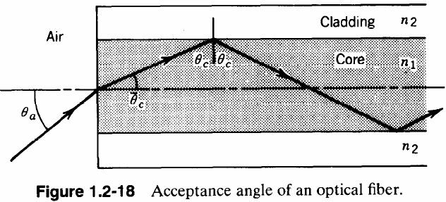
= n. 1 n. Next apply Snell s law at the cylindrical boundary between the core and cladding for the marginal ray. = n 2. sin π 2.
 EXERCISE.-9 First, re-derive equation.-5 considering the possibility that the index at the entrance to the fiber bay be different than one. Snell s law at the entrance to the fiber is where all symbols
20. Aberration Theory
 0. Aberration Theory Wavefront aberrations ( 파면수차 ) Chromatic Aberration ( 색수차 ) Third-order (Seidel) aberration theory Spherical aberrations Coma Astigmatism Curvature of Field Distortion Aberrations
Einstein Classes, Unit No. 102, 103, Vardhman Ring Road Plaza, Vikas Puri Extn., Outer Ring Road New Delhi , Ph. : ,
 1 O P T I C S 1. Define resolving power of a telescope & microscope and give the expression for its resolving power. 2. Explain briefly the formation of mirage in deserts. 3. The radii of curvature of
nds = n 1 d 1 sec θ 1 + n 2 d 2 sec θ 2 δopl =0
 1 Exercise 1.1-1 The optical path length is given by OPL = Z C which for an optical ray, must be stationary nds = n 1 d 1 sec θ 1 + n d sec θ δopl =0 so the first derivative of the optical path length
Solutions to Problems in Chapter 2: Waves
 Solutions to Problems in Chapter 2: Waves [Figure and equation numbers in the answers are preceded by ii so as to avoid confusion with figure and equation numbers in the text.] 2.1 A chain of masses m
- 1 - θ 1. n 1. θ 2. mirror. object. image
 TEST 5 (PHY 50) 1. a) How will the ray indicated in the figure on the following page be reflected by the mirror? (Be accurate!) b) Explain the symbols in the thin lens equation. c) Recall the laws governing
Since focal length = focal power
 RAY OPTICS PREVIOUS EAMCET BITS (ENGINEERING ). The two lenses of an achromatic doublet should have : [EAMCET 009 E] ) equal powers ) equal dispersive powers ) equal ratio of their power and dispersive
Lecture 19 Optical MEMS (1)
") EEL6935 Advanced MEMS (Spring 5) Instructor: Dr. Huikai Xie Lecture 19 Optical MEMS (1) Agenda: Optics Review EEL6935 Advanced MEMS 5 H. Xie 3/8/5 1 Optics Review Nature of Light Reflection and Refraction
EEL6935 Advanced MEMS (Spring 5) Instructor: Dr. Huikai Xie Lecture 19 Optical MEMS (1) Agenda: Optics Review EEL6935 Advanced MEMS 5 H. Xie 3/8/5 1 Optics Review Nature of Light Reflection and Refraction
Offset Spheroidal Mirrors for Gaussian Beam Optics in ZEMAX
 Offset Spheroidal Mirrors for Gaussian Beam Optics in ZEMAX Antony A. Stark and Urs Graf Smithsonian Astrophysical Observatory, University of Cologne aas@cfa.harvard.edu 1 October 2013 This memorandum
Assignment 3 Due September 27, 2010
 Assignment 3 Due September 27, 2010 Text readings Stops section 5.3 Dispersing and Reflecting Prisms [sections 5.5.1 and 5.5.2] Optical systems section 5.7 Lens Aberrations [section 6.3] Be careful about
Physics 102: Lecture 16 Introduction to Mirrors
 Physics 102: Lecture 16 Introduction to Mirrors Physics 102: Lecture 16, Slide 1 Physics 102 recent lectures Light as a wave Lecture 14 EM waves Lecture 15 Polarization Lecture 20 & 21 Interference & diffraction
Concave mirrors. Which of the following ray tracings is correct? A: only 1 B: only 2 C: only 3 D: all E: 2& 3
 Concave mirrors Which of the following ray tracings is correct? A: only 1 B: only 2 C: only 3 D: all E: 2& 3 1 2 3 c F Point C: geometrical center of the mirror, F: focal point 2 Concave mirrors Which
Final examination. 3 hours (9am 12 noon) Total pages: 7 (seven) PLEASE DO NOT TURN OVER UNTIL EXAM STARTS PLEASE RETURN THIS BOOKLET
 Total pages: 7 (seven) PLEASE DO NOT TURN OVER UNTIL EXAM STARTS PLEASE RETURN THIS BOOKLET") 2.710 Final examination 3 hours (9am 12 noon) Total pages: 7 (seven) PLEASE DO NOT TURN OVER UNTIL EXAM STARTS Name: PLEASE RETURN THIS BOOKLET WITH YOUR SOLUTION SHEET(S) MASSACHUSETTS INSTITUTE OF TECHNOLOGY
2.710 Final examination 3 hours (9am 12 noon) Total pages: 7 (seven) PLEASE DO NOT TURN OVER UNTIL EXAM STARTS Name: PLEASE RETURN THIS BOOKLET WITH YOUR SOLUTION SHEET(S) MASSACHUSETTS INSTITUTE OF TECHNOLOGY
Chapter Ray Optics and Optical Instrument
 Chapter Ray Optics and Optical Instrument Q1. Focal length of a convex lens of refractive index 1.5 is 2 cm. Focal length of the lens when immersed in a liquid of refractive index of 1.25 will be [1988]
Physics 3312 Lecture 7 February 6, 2019
 Physics 3312 Lecture 7 February 6, 2019 LAST TIME: Reviewed thick lenses and lens systems, examples, chromatic aberration and its reduction, aberration function, spherical aberration How do we reduce spherical
For more sample papers visit :
 PHYSICS (THEORY) (Three hours) For more sample papers visit : www.4ono.com Answer all questions in Part I and six questions from Part II, choosing two questions from each of the Sections A, B and C. All
EP 225 Waves, Optics, and Fields
 EP 225 Waves, Optics, and Fields Website: http://physics.usask.ca/~hirose/ep225/ contains Course outline Laboratory instruction Notes Past exams Animation Instructor: Akira Hirose Office Physics 66 akira.hirose@usask.ca
Solutions: Homework 7
 Solutions: Homework 7 Ex. 7.1: Frustrated Total Internal Reflection a) Consider light propagating from a prism, with refraction index n, into air, with refraction index 1. We fix the angle of incidence
Light - electromagnetic radiation
 Astronomy & Light Astronomy is a science In science we know by doing experiments When multiple experiments give the same results we develop theories and laws In astronomy many of the experiments are done
Physical Principles of Electron Microscopy. 2. Electron Optics
 Physical Principles of Electron Microscopy 2. Electron Optics Ray Egerton University of Alberta and National Institute of Nanotechnology Edmonton, Canada www.tem-eels.ca regerton@ualberta.ca Properties
Optics for Engineers Chapter 9
 Optics for Engineers Chapter 9 Charles A. DiMarzio Northeastern University Mar. 204 Gaussian Beams Applications Many Laser Beams Minimum Uncertainty Simple Equations Good Approximation Extensible (e.g.
LECTURE 23: LIGHT. Propagation of Light Huygen s Principle
 LECTURE 23: LIGHT Propagation of Light Reflection & Refraction Internal Reflection Propagation of Light Huygen s Principle Each point on a primary wavefront serves as the source of spherical secondary
Second Edition. Fundamentals of. Optics. Devraj Singh
 Second Edition Fundamentals of Optics Devraj Singh Fundamentals of Optics SECOND EDITION DEVRAJ SINGH Assistant Professor and Head Department of Applied Physics Amity School of Engineering and Technology
LECTURE 23: LIGHT. Propagation of Light Huygen s Principle
 LECTURE 23: LIGHT Propagation of Light Reflection & Refraction Internal Reflection Propagation of Light Huygen s Principle Each point on a primary wavefront serves as the source of spherical secondary
Physics 20 Work Plan
 Units/Topics Time Frame Major Learning Outcomes Unit Major Resource(s) Assessment methods Unit 2 Wave Motion A. Properties of waves 1. Wave terminology 2. Universal wave equation 3. Principle of Superposition
Optics for Engineers Chapter 9
 Optics for Engineers Chapter 9 Charles A. DiMarzio Northeastern University Nov. 202 Gaussian Beams Applications Many Laser Beams Minimum Uncertainty Simple Equations Good Approximation Extensible (e.g.
Get Discount Coupons for your Coaching institute and FREE Study Material at RAY OPTICS - I
 RAY OPTICS - I 1. Refraction of Light 2. Laws of Refraction 3. Principle of Reversibility of Light 4. Refraction through a Parallel Slab 5. Refraction through a Compound Slab 6. Apparent Depth of a Liquid
Light.notebook May 03, 2016
 Unit 4 Light LIGHT.1 Describe the ray model of light. 16.1 LIGHT.2 Predict the effect of distance on light s illuminance. 16.1 LIGHT.3 Explain polarization and the Doppler effect. 16.2 LIGHT.4 Describe
Wave Propagation in Uniaxial Media. Reflection and Transmission at Interfaces
 Lecture 5: Crystal Optics Outline 1 Homogeneous, Anisotropic Media 2 Crystals 3 Plane Waves in Anisotropic Media 4 Wave Propagation in Uniaxial Media 5 Reflection and Transmission at Interfaces Christoph
PRINCIPLES OF PHYSICAL OPTICS
 PRINCIPLES OF PHYSICAL OPTICS C. A. Bennett University of North Carolina At Asheville WILEY- INTERSCIENCE A JOHN WILEY & SONS, INC., PUBLICATION CONTENTS Preface 1 The Physics of Waves 1 1.1 Introduction
Chapter 5 Wave-Optics Analysis of Coherent Optical Systems
 Chapter 5 Wave-Optics Analysis of Coherent Optical Systems January 5, 2016 Chapter 5 Wave-Optics Analysis of Coherent Optical Systems Contents: 5.1 A thin lens as a phase transformation 5.2 Fourier transforming
Lecture 4: Optics / C2: Quantum Information and Laser Science
 Lecture 4: ptics / C2: Quantum Information and Laser Science November 4, 2008 Gaussian Beam An important class of propagation problem concerns well-collimated, spatiall localized beams, such as those emanating
EDT 4 - Optics and Optical Instruments. Solutions
 EDT 4 - Optics and Optical Instruments Solutions. μ sin30 0 = μ 2sin r (Snell s law at st interface) μ 2sin r = μ 3sin45 0 (Snell s law at 2 nd interface) 30 0 μ Hence, μ sin30 0 = μ 3sin45 0 μ sin30 0
Physics 1302, Exam 3 Review
 c V Andersen, 2006 1 Physics 1302, Exam 3 Review The following is a list of things you should definitely know for the exam, however, the list is not exhaustive. You are responsible for all the material
VISUAL OPTICS LABORATORY POWER MEASUREMENTS. Prof.Dr.A.Necmeddin YAZICI. GAZİANTEP UNIVERSITY OPTİCAL and ACOUSTICAL ENGINEERING DEPARTMENT
 VISUAL OPTICS LABORATORY POWER MEASUREMENTS Prof.Dr.A.Necmeddin YAZICI GAZİANTEP UNIVERSITY OPTİCAL and ACOUSTICAL ENGINEERING DEPARTMENT http://opac.gantep.edu.tr/index.php/tr/ 1 SURFACE GEOMETRY 2 The
Grade 8 Science Unit 2: Optics Chapters 4, 5 and 6
 Grade 8 Science Unit 2: Optics Chapters 4, 5 and 6 At the end of this unit, students will be expected to 1. Provide examples of ideas and theories of light used in the past to explain observed properties.
Optical Physics of Rifle Scopes
 Optical Physics of Rifle Scopes A Senior Project By Ryan Perry Advisor, Dr. Glen Gillen Department of Physics, California Polytechnic University SLO June 8, 207 Approval Page Title: Optical Analysis of
Optics.
 Optics www.optics.rochester.edu/classes/opt100/opt100page.html Course outline Light is a Ray (Geometrical Optics) 1. Nature of light 2. Production and measurement of light 3. Geometrical optics 4. Matrix
Last Name: First Name Network-ID
 Last Name: First Name Network-ID Discussion Section: Discussion TA Name: Turn off your cell phone and put it out of sight. Keep your calculator on your own desk. Calculators cannot be shared. This is a
General Physics II Summer Session 2013 Review Ch - 16, 17, 18
 95.104 General Physics II Summer Session 2013 Review Ch - 16, 17, 18 A metal ball hangs from the ceiling by an insulating thread. The ball is attracted to a positivecharged rod held near the ball. The
OPTICAL INSTRUMENTS VERY SHORT ANSWER QUESTIONS
 OPTICAL INSTRUMENTS VERY SHORT ANSWER QUESTIONS Q-1. The difference in the focal lengths of the two lenses is larger in which case microscope or telescope? Q-2. What is the formula for angular magnification
Vågrörelselära och optik
 Vågrörelselära och optik Harmonic oscillation: Experiment Experiment to find a mathematical description of harmonic oscillation Kapitel 14 Harmonisk oscillator 1 2 Harmonic oscillation: Experiment Harmonic
Magnifying Glass. Angular magnification (m): 25 cm/f < m < 25cm/f + 1. image at 25 cm (= normal near point) relaxed eye, image at (normal) far point
: 25 cm/f < m < 25cm/f + 1. image at 25 cm (= normal near point) relaxed eye, image at (normal) far point") Magnifying Glass Angular magnification (m): 25 cm/f < m < 25cm/f + 1 relaxed eye, image at (normal) far point image at 25 cm (= normal near point) For more magnification, first use a lens to form an enlarged
Magnifying Glass Angular magnification (m): 25 cm/f < m < 25cm/f + 1 relaxed eye, image at (normal) far point image at 25 cm (= normal near point) For more magnification, first use a lens to form an enlarged
M3/4A16 Assessed Coursework 1 Darryl Holm Due in class Thursday November 6, 2008 #1 Eikonal equation from Fermat s principle
 D. D. Holm November 6, 2008 M3/416 Geom Mech Part 1 1 M3/416 ssessed Coursework 1 Darryl Holm Due in class Thursday November 6, 2008 #1 Eikonal equation from Fermat s principle #1a Prove that the 3D eikonal
 Optics. The refractive index of a material of a plain concave lens is 5/3, the radius of curvature is 0.3m. The focal length of the lens in air is ) 0.45 m ) 0.6 m 3) 0.75 m 4).0 m. The refractive index
The Principle of Least Action
 The Principle of Least Action In their never-ending search for general principles, from which various laws of Physics could be derived, physicists, and most notably theoretical physicists, have often made
Course Secretary: Christine Berber O3.095, phone x-6351,
 IMPRS: Ultrafast Source Technologies Franz X. Kärtner (Umit Demirbas) & Thorsten Uphues, Bldg. 99, O3.097 & Room 6/3 Email & phone: franz.kaertner@cfel.de, 040 8998 6350 thorsten.uphues@cfel.de, 040 8998
Nature of Light Part 2
 Nature of Light Part 2 Fresnel Coefficients From Helmholts equation see imaging conditions for Single lens 4F system Diffraction ranges Rayleigh Range Diffraction limited resolution Interference Newton
nr 2 nr 4 Correct Answer 1 Explanation If mirror is rotated by anglethan beeping incident ray fixed, reflected ray rotates by 2 Option 4
 Q. No. A small plane mirror is placed at the centero a spherical screen o radius R. A beam o light is alling on the mirror. I the mirror makes n revolution per second, the speed o light on the screen ater
Review problems for the final exam Calculus III Fall 2003
 Review problems for the final exam alculus III Fall 2003 1. Perform the operations indicated with F (t) = 2t ı 5 j + t 2 k, G(t) = (1 t) ı + 1 t k, H(t) = sin(t) ı + e t j a) F (t) G(t) b) F (t) [ H(t)
Saint Lucie County Science Scope and Sequence
 Course: Physics 1 Course Code: 2003380 SEMESTER 2 QUARTER 3 UNIT 7 TOPIC of STUDY: Thermal Energy STANDARDS: 8:Matter, 10: Energy, 12: Motion KEY LEARNING: ~Mathematically relate heat, phase change, energy,
Optics Purpose Discover the basics of geometric optics Understand the principles behind a refractor and a reflector telescope
 Name: Partner(s): 1102 or 3311: Desk # Date: Optics Purpose Discover the basics of geometric optics Understand the principles behind a refractor and a reflector telescope Equipment Various lenses and mirrors
Seismology and Seismic Imaging
 Seismology and Seismic Imaging 4. Ray theory N. Rawlinson Research School of Earth Sciences, ANU Seismology lecture course p.1/23 The ray approximation Here, we consider the problem of how body waves (P
LIGHT. A beam is made up of several rays. It maybe parallel, diverging (spreading out) or converging (getting narrower). Parallel Diverging Converging
 or converging (getting narrower). Parallel Diverging Converging") LIGHT Light is a form of energy. It stimulates the retina of the eye and produces the sensation of sight. We see an object when light leaves it and enters the eye. Objects such as flames, the sum and stars
LIGHT Light is a form of energy. It stimulates the retina of the eye and produces the sensation of sight. We see an object when light leaves it and enters the eye. Objects such as flames, the sum and stars
Part 1 - Basic Interferometers for Optical Testing
 Part 1 - Basic Interferometers for Optical Testing Two Beam Interference Fizeau and Twyman-Green interferometers Basic techniques for testing flat and spherical surfaces Mach-Zehnder Zehnder,, Scatterplate
LESSON RAY OPTICS Introduction Note Ray of light Beam of light Reflection of Light by Spherical Mirrors Law of reflection Note:
 2 LESSON RAY OPTICS Introduction Electromagnetic radiation belonging to the region of the electromagnetic spectrum (wavelength of about 400 nm to 750 nm) is called light. Nature has endowed the human eye
MICROSCOPY COURSE 2012
 MICROSCOPY COURSE 2012 INTRODUCTION TO BASIC LIGHT MICROSCOPY AIM OF THE COURSE Teach basic principles of light microscopy Theoretical background Practical aspects Faced towards applications of light microscopy
Gen. Phys. II Exam 3 - Chs. 24,25,26 - EM Waves, Ray Optics, Optical Instruments Mar. 26, 2018
 Gen. Phys. II Exam 3 - Chs. 24,25,26 - EM Waves, Ray Optics, Optical Instruments Mar. 26, 2018 Rec. Time Name For full credit, make your work clear. Show formulas used, essential steps, and results with
Applications of the Abbe Sine Condition in Multi-Channel Imaging Systems
 Applications of the Abbe Sine Condition in Multi-Channel Imaging Systems Barbara Kruse, University of Arizona, College of Optical Sciences May 6, 2016 Abstract Background In multi-channel imaging systems,
Astronomical Optics. Second Edition DANIEL J. SCHROEDER ACADEMIC PRESS
 Astronomical Optics Second Edition DANIEL J. SCHROEDER Professor of Physics and Astronomy, Emeritus Department of Physics and Astronomy Beloit College, Beloit, Wisconsin ACADEMIC PRESS A Harcourt Science
Where k = 1. The electric field produced by a point charge is given by
 Ch 21 review: 1. Electric charge: Electric charge is a property of a matter. There are two kinds of charges, positive and negative. Charges of the same sign repel each other. Charges of opposite sign attract.
MIDTERM 3 REVIEW SESSION. Dr. Flera Rizatdinova
 MIDTERM 3 REVIEW SESSION Dr. Flera Rizatdinova Summary of Chapter 23 Index of refraction: Angle of reflection equals angle of incidence Plane mirror: image is virtual, upright, and the same size as the
Exam 3 Solutions. Answer: 1830 Solution: Because of equal and opposite electrical forces, we have conservation of momentum, m e
 Exam 3 Solutions Prof. Paul Avery Prof. Zongan iu Apr. 27, 2013 1. An electron and a proton, located far apart and initially at rest, accelerate toward each other in a location undisturbed by any other
Electromagnetic Implosion Using a Lens
 Sensor and Simulation Notes Note 516 July 2006 Electromagnetic Implosion Using a Lens Carl E. Baum University of New Mexico Department of Electrical and Computer Engineering Albuquerque New Mexico 87131
λ Fig. 2 Name: y direction. In what c) in the + y direction d) in the y direction e) in the x direction
 in the + y direction d) in the y direction e) in the x direction") Name: Exam #3 D#: Physics 140 Section #: hoose the best answer for each of Questions 1-19 below. Mark your answer on your scantron form using a # pencil. (5.6 pts each) 1. At a certain instant in time,
Name: Exam #3 D#: Physics 140 Section #: hoose the best answer for each of Questions 1-19 below. Mark your answer on your scantron form using a # pencil. (5.6 pts each) 1. At a certain instant in time,
PHYS 1112 In-Class Exam #1, Version D
 PHYS 1112 In-Class Exam #1, Version D Tue. Feb. 4, 2014, 11:00am-12:15am This is a closed-book, closed-notes exam, but you are permitted to bring and use a clean copy of the official Formula Sheet for
PHYSICS. Ray Optics. Mr Rishi Gopie
 Ray Optics Mr Rishi Gopie Ray Optics Nature of light Light is a form of energy which affects the human eye in such a way as to cause the sensation of sight. Visible light is a range of electromagnetic
School. Team Number. Optics
 School Team Number Optics Physical Optics (30%) Proceed to the laser shoot (40%) when your team number is called. 1. What are the four colors used in the CMYK color model? (2 points) 2. Muscae Volitantes
Physics 351, Spring 2017, Homework #4. Due at start of class, Friday, February 10, 2017
 Physics 351, Spring 2017, Homework #4. Due at start of class, Friday, February 10, 2017 Course info is at positron.hep.upenn.edu/p351 When you finish this homework, remember to visit the feedback page
Unit 4 Parent Guide: Waves. What is a wave?
 Unit 4 Parent Guide: Waves What is a wave? A wave is a disturbance or vibration that carries energy from one location to another. Some waves require a medium to transmit the energy whereas others can travel
Vector diffraction theory of refraction of light by a spherical surface
 S. Guha and G. D. Gillen Vol. 4, No. 1/January 007/J. Opt. Soc. Am. B 1 Vector diffraction theory of refraction of light by a spherical surface Shekhar Guha and Glen D. Gillen* Materials and Manufacturing
A) n 1 > n 2 > n 3 B) n 1 > n 3 > n 2 C) n 2 > n 1 > n 3 D) n 2 > n 3 > n 1 E) n 3 > n 1 > n 2
 n 1 > n 2 > n 3 B) n 1 > n 3 > n 2 C) n 2 > n 1 > n 3 D) n 2 > n 3 > n 1 E) n 3 > n 1 > n 2") 55) The diagram shows the path of a light ray in three different materials. The index of refraction for each material is shown in the upper right portion of the material. What is the correct order for
55) The diagram shows the path of a light ray in three different materials. The index of refraction for each material is shown in the upper right portion of the material. What is the correct order for
= 115V. = = = C/m 2
 SPHS Class th Physics Solution. parallel-plate air capacitor has a plate area of cm and separation 5mm. potential difference of V is established between its plates by a battery. fter disconnecting a battery,
IMPRS: Ultrafast Source Technologies
 IMPRS: Ultrafast Source Technologies Fran X. Kärtner & Thorsten Uphues, Bldg. 99, O3.097 & Room 6/3 Email & phone: fran.kaertner@cfel.de, 040 8998 6350 Thorsten.Uphues@cfel.de, 040 8998 706 Lectures: Tuesday
21. Propagation of Gaussian beams
 1. Propagation of Gaussian beams How to propagate a Gaussian beam Rayleigh range and confocal parameter Transmission through a circular aperture Focusing a Gaussian beam Depth of field Gaussian beams and
High-Resolution. Transmission. Electron Microscopy
 Part 4 High-Resolution Transmission Electron Microscopy 186 Significance high-resolution transmission electron microscopy (HRTEM): resolve object details smaller than 1nm (10 9 m) image the interior of
THE PARAXIAL WAVE EQUATION GAUSSIAN BEAMS IN UNIFORM MEDIA:
 THE PARAXIAL WAVE EQUATION GAUSSIAN BEAMS IN UNIFORM MEDIA: In point-to-point communication, we may think of the electromagnetic field as propagating in a kind of "searchlight" mode -- i.e. a beam of finite
Light matter interaction. Ground state spherical electron cloud. Excited state : 4 quantum numbers n principal (energy)
") Light matter interaction Hydrogen atom Ground state spherical electron cloud Excited state : 4 quantum numbers n principal (energy) L angular momentum, 2,3... L L z projection of angular momentum S z projection
Light matter interaction Hydrogen atom Ground state spherical electron cloud Excited state : 4 quantum numbers n principal (energy) L angular momentum, 2,3... L L z projection of angular momentum S z projection
PHYSICS PAPER 1 (THEORY) (Three hours)
 (Three hours)") PHYSICS PAPER 1 (THEORY) (Three hours) (Candidates are allowed additional 15 minutes for only reading the paper. They must OT start writing during this time.) ---------------------------------------------------------------------------------------------------------------------
PHYSICS PAPER 1 (THEORY) (Three hours) (Candidates are allowed additional 15 minutes for only reading the paper. They must OT start writing during this time.) ---------------------------------------------------------------------------------------------------------------------
I. HARTLE CHAPTER 8, PROBLEM 2 (8 POINTS) where here an overdot represents d/dλ, must satisfy the geodesic equation (see 3 on problem set 4)
 where here an overdot represents d/dλ, must satisfy the geodesic equation (see 3 on problem set 4)") Physics 445 Solution for homework 5 Fall 2004 Cornell University 41 points) Steve Drasco 1 NOTE From here on, unless otherwise indicated we will use the same conventions as in the last two solutions: four-vectors
Physics 445 Solution for homework 5 Fall 2004 Cornell University 41 points) Steve Drasco 1 NOTE From here on, unless otherwise indicated we will use the same conventions as in the last two solutions: four-vectors
3.1 The Plane Mirror Resonator 3.2 The Spherical Mirror Resonator 3.3 Gaussian modes and resonance frequencies 3.4 The Unstable Resonator
 Quantum Electronics Laser Physics Chapter 3 The Optical Resonator 3.1 The Plane Mirror Resonator 3. The Spherical Mirror Resonator 3.3 Gaussian modes and resonance frequencies 3.4 The Unstable Resonator