Homework 5 Due 28 October at 6:00 pm
|
|
|
- Timothy Fitzgerald
- 6 years ago
- Views:
Transcription
1 1. Resistance Calculations Homework 5 Due 28 October at 6:00 pm Plus Electrode Minus Electrode Assume that we have a thin conductor deposited onto the surface of a plastic board (as on a printed circuit board). The conductor is L-shaped, so any current passing through it must turn a corner. The square region in which the conductor is found is 10cm by 10cm. The conductor is 4cm wide and 1mm thick. To keep things simple, we will assume a conductivity of σ = 10 as might be obtained using some kind of salty water solution. a. Using the simplest possible model, find the resistance of this conductor. That is, assume it has the given width and assume a length that includes all of the conducting material. Then, being careful about units, find the resistance. b. Next, use the plot below to find a more accurate value for the resistance. This plot, generated using FEMM, shows the equipotentials. To use this plot, carefully draw electric field lines in sufficient number to form curvilinear squares. That is, each cell formed by two equipotentials and two field lines should be approximately square. Once you have this diagram, then find the resistance but first finding the resistance of a single cell and then combine the cells in series and parallel to get the final answer. The plot labels two regions as air, but that is just an artifact of the method used. Assume the region shown is a conductor. c. Now you should solve this problem using a spreadsheet. To do this, you assume that the region of interest is made of a single material. It really does not matter whether the material is a dielectric or conductor, since the potentials will be the same, because you only need to use Laplace s equation. Solve for the voltages in the region of interest. Once you have obtained your solution, save your results and then load them into Matlab using a modification of the file provided on the handout page. This file applies to an excel solution to a square blob in a parallel plate region, also provided. (continued below) Fields and Waves I Homework 5 Fall 2009 K. A. Connor October
2 Hint: You can find some useful background information by searching for info on curvilinear squares and/or flownets. The Matlab file allows us to produce streamlines from equipotentials. Our streamlines are the electric field lines. The method is not perfect, so that it is really only accurate for about half of the structure. This is shown in the example provided. To achieve the best accuracy using this method, only use the field lines from the upper half of the configuration, as shown, and then double your answer. The advantage of using this method is that you do not have to sketch the field lines by hand. However, we are stuck with its inaccuracies, such as they are. Be sure to point out the inaccuracies in your results and fully label your plots. Fields and Waves I Homework 5 Fall 2009 K. A. Connor October


3 1 4 7 For the spreadsheet solution, the equipotentials look like. S100 S97 S94 S91 S88 S85 S82 S79 S76 S73 S70 S67 S64 S61 S58 S55 S52 S49 S46 S43 S40 S S34 S31 S28 S25 S22 S19 S16 S13 S10 S7 S4 S The yellow cells are set equal to their interior neighbor cell, the orange cells are at fixed voltages and the brown cells are set equal to the average of their four neighbors. Fields and Waves I Homework 5 Fall 2009 K. A. Connor October
4 The modified m-file for this case: % Plotting Data from Excel % K. A. Connor % Input Data from Excel for a Laplace's Equation Solution % First, you need to know what part of the excel file holds your data % Second, copy the file into the Matlab Workspace so you have access to it % V=xlsread('file.xls','upper left cell: lower right cell'); % Name the array (usually some kind of voltage) v=xlsread('h4.xls','a1:cw101'); % Position array for plotting d=size(v); [x,y]=meshgrid(0:(d(1)-1)/100:(d(1)-1),0:(d(2)-1)/100:(d(2)-1)); % Calculate the E field using the gradient function % [Ex,Ey]=gradient(-V);%Don't forget the negative sign [ex,ey]=gradient(-v); % For streamlines one needs to specify where they should start % It is a good idea to start them uniformly distributed around the largest % electrode. [sx,sy]=meshgrid(0:100,1); %Note that the range of points is % shown in one or the other of the parameters.; [sx,sy]=meshgrid(1,4:4:36); [tx,ty]=meshgrid(64:4:96,100); % Plotting contour(x,y,v,35);hold on;axis square; h=streamline(ex,ey,sx,sy);set(h, 'Color', 'green'); g=streamline(-ex,-ey,tx,ty);set(g, 'Color', 'black'); x1=[0 60];y1=[40 40]; line(x1,y1) x2=[60 60];y2=[40 100]; line(x2,y2) Note: The last two line functions show the edges of the region. Fields and Waves I Homework 5 Fall 2009 K. A. Connor October
5 The plot from Mablab shows streamlines (E field lines) plotted from each electrode. Note that they become less accurate after they turn the corner. Thus, we only use half of the figure and then multiply the result by 2 to obtain the full resistance. Note that the E lines would be the same drawn from both electrodes if they had no errors. The solution is probably not even totally accurate as far as the corner, but using only half of the field structure seems to be a reasonable approximation The black E lines are evenly distributed until they reach the corner, after which they seem to move up The green E lines are evenly distributed until they reach the corner, after which they seem to move to the right We use a red line to mark the useful half of the structure and then focus on the black cells in the upper leg. There are 10 cells across and 18 down. Each cell has a resistance of 100 Ohms as before so the total is times 2 or 360 Ohms. Both of the numerical 10 solutions are more accurate than the simple formula (see explanation in problem 2). Fields and Waves I Homework 5 Fall 2009 K. A. Connor October
6 2. Resistance of Spiral The configuration below shows a spiral conductor formed on the surface of a plastic board. (From FEMM) The overall region is again 10cm by 10cm with the conducting stripe exactly 1cm wide and 1mm thick. The two connections for the conductor are shown in red. That is the current flows from one to the other a. Again, begin by determine the simplest possible solution for the resistance of this configuration. b. Next, use the information from FEMM to determine a more accurate solution. Again, you want to form the individual square cells of the curvilinear squares method. c. Discuss why your answers differ and why it is reasonable that one is smaller than the other. Fields and Waves I Homework 5 Fall 2009 K. A. Connor October


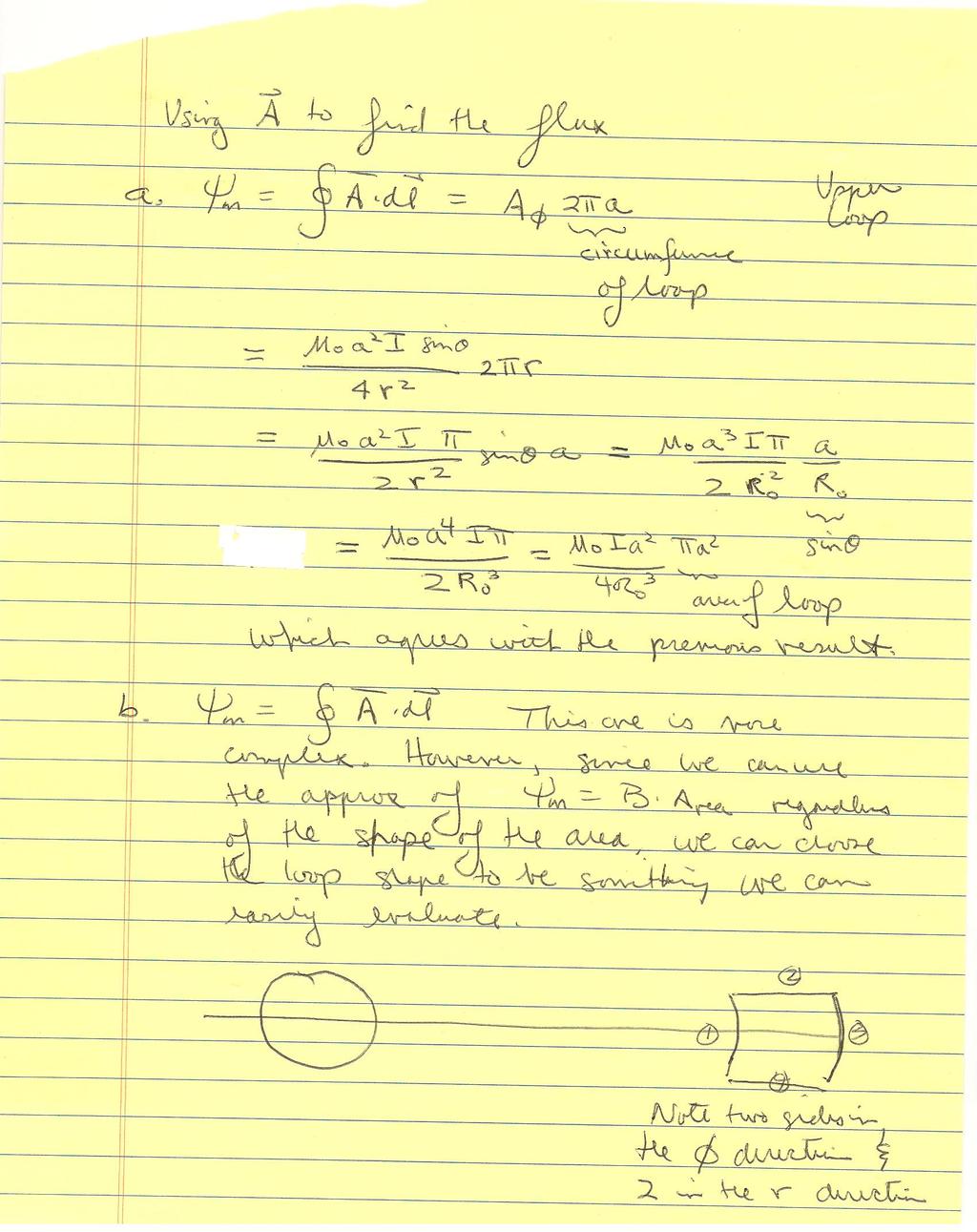
7 The same information is shown below, along with a false color plot of the electric field intensity. Label the regions in this plot where the electric field is the largest and where it is the smallest. Also note the regions in which the electric field intensity is reasonably uniform. Provide an explanation to accompany your labels. 3. Magnetic Vector Potential & Magnetic Flux A magnetic dipole is one of the most fundamental and useful magnetic configurations. The orientation of the dipole is along the z- axis. The magnitude of the dipole is m = I Area = Iπa 2 One of the most useful characteristics of the magnetic vector potential is that it has vector components only in the direction of the current that generates it. In this case, that means that the vector potential must only have a φ component. For distances that are not too close to the loop, the vector potential is given by A Fields and Waves I Homework 5 Fall 2009 K. A. Connor October φ μo Iπa = 2 4πr 2 sin θ.
8 a. Determine the magnetic field r B in vector form from the expression above for the vector potential. b. Determine the magnetic flux passing through the two loops shown below for the given magnetic vector potential field. Determine the flux using both the expressions for r Aand r B. The two answers should be the same. For all four integrals, you can assume that the distances between the loops is large compared to their diameters (all three =2a) z R o x y R o 4. Ampere s Law a. A beam of charged particles is directed axially down the center of a conducting pipe of radius b. The current density in the beam is given by 4 r r J = Jo 1 a$ 4 a z in the region a r b and zero elsewhere. Determine the total current carried by this beam. Assume that this current must be returned as a surface current at r=b. Determine J r s. b. From the source distribution you have given in part a, determine the magnetic field B r everywhere in space using Ampere s Law in integral form. c. Confirm that your answer to part b is correct by showing that it satisfies the differential forms of Maxwell s equations for magnetostatics (both the curl and divergence equations). Fields and Waves I Homework 5 Fall 2009 K. A. Connor October

9
10
11

12
13

14

15

16

17
PHYSICS ASSIGNMENT ES/CE/MAG. Class XII
 PHYSICS ASSIGNMENT ES/CE/MAG Class XII MM : 70 1. What is dielectric strength of a medium? Give its value for vacuum. 1 2. What is the physical importance of the line integral of an electrostatic field?
Reading Assignments Please see the handouts for each lesson for the reading assignments.
 Preparation Assignments for Homework #5 Due at the start of class. These assignments will only be accepted from students attending class. Reading Assignments Please see the handouts for each lesson for
No prep assignment to do, but here are four questions anyway.
 Preparation Assignments for Homework #3 Due at the start of class. Reading Assignments Please see the handouts for each lesson for the reading assignments. 3,4 February Lesson 2.5 No prep assignment to
Homework 4 Part One Due 14 October at 6:00 pm
 1. Coaxial Cable Electric Field Homework 4 Part One Due 14 October at 6:00 pm r a. Using the solution to problem 2 of HW3, write the electric field Er () of the CATV coaxial cable in full vector form (with
o Two-wire transmission line (end view is shown, the radius of the conductors = a, the distance between the centers of the two conductors = d)
") Homework 2 Due Monday, 14 June 1. There is a small number of simple conductor/dielectric configurations for which we can relatively easily find the capacitance. Students of electromagnetics should be sure
Homework 2 Due Monday, 14 June 1. There is a small number of simple conductor/dielectric configurations for which we can relatively easily find the capacitance. Students of electromagnetics should be sure
CHAPTER 2. COULOMB S LAW AND ELECTRONIC FIELD INTENSITY. 2.3 Field Due to a Continuous Volume Charge Distribution
 CONTENTS CHAPTER 1. VECTOR ANALYSIS 1. Scalars and Vectors 2. Vector Algebra 3. The Cartesian Coordinate System 4. Vector Cartesian Coordinate System 5. The Vector Field 6. The Dot Product 7. The Cross
3 December Lesson 5.5
 Preparation Assignments for Homework #8 Due at the start of class. Reading Assignments Please see the handouts for each lesson for the reading assignments. 3 December Lesson 5.5 A uniform plane wave is
ELECTRO MAGNETIC FIELDS
 SET - 1 1. a) State and explain Gauss law in differential form and also list the limitations of Guess law. b) A square sheet defined by -2 x 2m, -2 y 2m lies in the = -2m plane. The charge density on the
Physics 112. Study Notes for Exam II
 Chapter 20 Electric Forces and Fields Physics 112 Study Notes for Exam II 4. Electric Field Fields of + and point charges 5. Both fields and forces obey (vector) superposition Example 20.5; Figure 20.29
Unit-1 Electrostatics-1
 1. Describe about Co-ordinate Systems. Co-ordinate Systems Unit-1 Electrostatics-1 In order to describe the spatial variations of the quantities, we require using appropriate coordinate system. A point
Electromagnetic Field Theory Chapter 9: Time-varying EM Fields
 Electromagnetic Field Theory Chapter 9: Time-varying EM Fields Faraday s law of induction We have learned that a constant current induces magnetic field and a constant charge (or a voltage) makes an electric
Problem info Geometry model Labelled Objects Results Nonlinear dependencies
 Problem info Problem type: Transient Magnetics (integration time: 9.99999993922529E-09 s.) Geometry model class: Plane-Parallel Problem database file names: Problem: circuit.pbm Geometry: Circuit.mod Material
There are four questions on this exam. All are of equal value but not necessarily of equal difficulty. Answer all four questions
 Electricity and Magnetism (PHYS2016) Second Semester Final Exam 2015 There are four questions on this exam. All are of equal value but not necessarily of equal difficulty. Answer all four questions You
Experiment 5: Measurements Magnetic Fields
 Experiment 5: Measurements Magnetic Fields Introduction In this laboratory you will use fundamental electromagnetic Equations and principles to measure the magnetic fields of two magnets. 1 Physics 1.1
UNIT I ELECTROSTATIC FIELDS
 UNIT I ELECTROSTATIC FIELDS 1) Define electric potential and potential difference. 2) Name few applications of gauss law in electrostatics. 3) State point form of Ohm s Law. 4) State Divergence Theorem.
Chap. 1 Fundamental Concepts
 NE 2 Chap. 1 Fundamental Concepts Important Laws in Electromagnetics Coulomb s Law (1785) Gauss s Law (1839) Ampere s Law (1827) Ohm s Law (1827) Kirchhoff s Law (1845) Biot-Savart Law (1820) Faradays
PHYS 1444 Section 004 Lecture #10
 PHYS 1444 Section 004 Lecture #10 Dr. Electric Current and Resistance The Battery Ohm s Law: Resisters Resistivity Electric Power Alternating Current Power Delivered by AC Today s homework is #6, due 10pm,
EE301 RESISTANCE AND OHM S LAW
 Learning Objectives a. Describe the concept of resistance b. Use Ohm s law to calculate current, voltage, and resistance values in a circuit c. Discuss the difference between an open circuit and a short
Chapter 1 The Electric Force
 Chapter 1 The Electric Force 1. Properties of the Electric Charges 1- There are two kinds of the electric charges in the nature, which are positive and negative charges. - The charges of opposite sign
MAGNETIC EFFECT OF CURRENT
 MAGNETIC EFFECT OF CURRENT VERY SHORT ANSWER QUESTIONS Q.1 Who designed cyclotron? Q.2 What is the magnetic field at a point on the axis of the current element? Q.3 Can the path of integration around which
Lab #6 Ohm s Law. Please type your lab report for Lab #6 and subsequent labs.
 Dr. Day, Fall 2004, Rev. 06/22/10 HEFW PH 262 Page 1 of 4 Lab #6 Ohm s Law Please type your lab report for Lab #6 and subsequent labs. Objectives: When you have completed this lab exercise you should be
Electrical Machines-I Prof. D. Kastha Department of Electrical Engineering Indian Institute of Technology, Kharagpur
 Electrical Machines-I Prof. D. Kastha Department of Electrical Engineering Indian Institute of Technology, Kharagpur Lecture - 20 Potential and Current Transformers (Refer Slide Time: 00:37) So far we
Electrostatics. Chapter Maxwell s Equations
 Chapter 1 Electrostatics 1.1 Maxwell s Equations Electromagnetic behavior can be described using a set of four fundamental relations known as Maxwell s Equations. Note that these equations are observed,
AP Physics C. Electricity - Term 3
 AP Physics C Electricity - Term 3 Interest Packet Term Introduction: AP Physics has been specifically designed to build on physics knowledge previously acquired for a more in depth understanding of the
UNIT-III Maxwell's equations (Time varying fields)
") UNIT-III Maxwell's equations (Time varying fields) Faraday s law, transformer emf &inconsistency of ampere s law Displacement current density Maxwell s equations in final form Maxwell s equations in word
UNIT-III Maxwell's equations (Time varying fields) Faraday s law, transformer emf &inconsistency of ampere s law Displacement current density Maxwell s equations in final form Maxwell s equations in word
TECHNO INDIA BATANAGAR
 TECHNO INDIA BATANAGAR ( DEPARTMENT OF ELECTRONICS & COMMUNICATION ENGINEERING) QUESTION BANK- 2018 1.Vector Calculus Assistant Professor 9432183958.mukherjee@tib.edu.in 1. When the operator operates on
NASSP Honours Electrodynamics Part 1. Tutorial Problem Set 2: Magnetic Materials, Time Varying Fields
 NASSP Honours Electrodynamics Part 1 Tutorial Problem Set 2: Magnetic Materials, Time Varying Fields Q.1. At the interface between one linear magnetic material and another (relative permeabilities and
Electric Fields and Potentials
 Electric Fields and Potentials INTRODUCTION Physicists use the concept of a field to explain the interaction of particles or bodies through space, i.e., the action-at-a-distance force between two bodies
TENTATIVE CONTENTS OF THE COURSE # EE-271 ENGINEERING ELECTROMAGNETICS, FS-2012 (as of 09/13/12) Dr. Marina Y. Koledintseva
 Dr. Marina Y. Koledintseva") TENTATIVE CONTENTS OF THE COURSE # EE-271 ENGINEERING ELECTROMAGNETICS, FS-2012 (as of 09/13/12) Dr. Marina Y. Koledintseva Part 1. Introduction Basic Physics and Mathematics for Electromagnetics. Lecture
TENTATIVE CONTENTS OF THE COURSE # EE-271 ENGINEERING ELECTROMAGNETICS, FS-2012 (as of 09/13/12) Dr. Marina Y. Koledintseva Part 1. Introduction Basic Physics and Mathematics for Electromagnetics. Lecture
CHAPTER 7 ELECTRODYNAMICS
 CHAPTER 7 ELECTRODYNAMICS Outlines 1. Electromotive Force 2. Electromagnetic Induction 3. Maxwell s Equations Michael Faraday James C. Maxwell 2 Summary of Electrostatics and Magnetostatics ρ/ε This semester,
Magnetostatics: Part 1
 Magnetostatics: Part 1 We present magnetostatics in comparison with electrostatics. Sources of the fields: Electric field E: Coulomb s law. Magnetic field B: Biot-Savart law. Charge Current (moving charge)
6.013 Recitation 11. Quasistatic Electric and Magnetic Fields in Devices and Circuit Elements
 6.013 Recitation 11 Quasistatic Electric and Magnetic Fields in Devices and Circuit Elements A. Introduction The behavior of most electric devices depends on static or slowly varying (quasistatic 1 ) electric
PHY222 Lab 2 - Electric Fields Mapping the Potential Curves and Field Lines of an Electric Dipole
 Print Your Name PHY222 Lab 2 - Electric Fields Mapping the Potential Curves and Field Lines of an Electric Dipole Print Your Partners' Names Instructions January 23, 2015 Before lab, read the Introduction,
Electric Field Mapping
 Electric Field Mapping Equipment: mapping board, U-probe, 5 resistive boards, templates, knob adjustable DC voltmeter, 4 long leads, 16 V DC for wall strip, 8 1/2 X 11 sheets of paper Reading: Topics of
Experiment 1 Solutions: Equipotential Lines and Electric Fields
 MASSACHUSETTS INSTITUTE OF TECHNOLOGY Department of Physics 8.02 Experiment 1 Solutions: Equipotential Lines and Electric Fields IN-LAB ACTIVITIES EXPERIMENTAL SETUP 1. Download the LabView file from the
NR/RR. Set No. 2 CODE NO: NR/RR210204
 Set No. 2 II B.Tech I Semester Examinations,May 2011 ELECTROMAGNETIC FIELDS Electrical And Electronics Engineering Time: 3 hours Max Marks: 80 Answer any FIVE Questions All Questions carry equal marks
Electromagnetic Theory Prof. D. K. Ghosh Department of Physics Indian Institute of Technology, Bombay
 Electromagnetic Theory Prof. D. K. Ghosh Department of Physics Indian Institute of Technology, Bombay Module -4 Time Varying Lecture - 29 Faraday s Law and Inductance In the previous lecture, we had started
Electric Field Mapping
 Electric Field Mapping Objectives To determine the equipotential lines and the corresponding electric field lines for a variety of arrangements of conductors in a plane. Theory The concept of an electric
Electric Fields and Equipotentials
 OBJECTIVE Electric Fields and Equipotentials To study and describe the two-dimensional electric field. To map the location of the equipotential surfaces around charged electrodes. To study the relationship
LABORATORY 4 ELECTRIC CIRCUITS I. Objectives
 LABORATORY 4 ELECTRIC CIRCUITS I Objectives to be able to discuss potential difference and current in a circuit in terms of electric field, work per unit charge and motion of charges to understand that
LAB 03 Electric Fields and Potentials
 Group: LAB 03 Electric Fields and Potentials Names: (Principle Coordinator) (Lab Partner) (Lab Partner) Motto: Say map! Say map! Dora the Explorer Goals: Developing an intuitive picture of the electric
Problem Solving 9: Displacement Current, Poynting Vector and Energy Flow
 MASSACHUSETTS INSTITUTE OF TECHNOLOGY Department of Physics Problem Solving 9: Displacement Current, Poynting Vector and Energy Flow Section Table and Group Names Hand in one copy per group at the end
Mansfield Independent School District AP Physics C: Electricity and Magnetism Year at a Glance
 Mansfield Independent School District AP Physics C: Electricity and Magnetism Year at a Glance First Six-Weeks Second Six-Weeks Third Six-Weeks Lab safety Lab practices and ethical practices Math and Calculus
AP Physics C. Magnetism - Term 4
 AP Physics C Magnetism - Term 4 Interest Packet Term Introduction: AP Physics has been specifically designed to build on physics knowledge previously acquired for a more in depth understanding of the world
PHYSICS 221 LAB #3: ELECTROSTATICS
 Name: Partners: PHYSICS 221 LAB #3: ELECTROSTATICS The picture above shows several lines that each have a constant electric potential (equipotential lines) due to a person s beating heart. At the instant
AP Physics C Electricity and Magnetism
 AP Physics C Electricity and Magnetism Course overview This is a calculus based course in physics. The course is the equivalent of an introductory engineering course in Physics. The main objective of the
Do not fill out the information below until instructed to do so! Name: Signature: Section Number:
 Do not fill out the information below until instructed to do so! Name: Signature: E-mail: Section Number: No calculators are allowed in the test. Be sure to put a box around your final answers and clearly
Basic Electricity and Magnetism 3910
 Basic Electricity and Magnetism 3910 Current Flow in Ohmic Resistors The general problem Most materials are characterized by a bulk parameter called resistivity, symbolized by ρ. The resistivity can be
Experiment VIII Equipotentials and Fields
 Experiment VIII Equipotentials and Fields I. References Serway and Jewett, Vol. 2, Chapter 25 II. Apparatus 4 electrode boards docking station for electrode boards 2 templates for drawing electrodes DC
ST.JOSEPH COLLEGE OF ENGINEERING,DEPARTMENT OF ECE
 EC6403 -ELECTROMAGNETIC FIELDS CLASS/SEM: II ECE/IV SEM UNIT I - STATIC ELECTRIC FIELD Part A - Two Marks 1. Define scalar field? A field is a system in which a particular physical function has a value
Lab: Electric Potential & Electric Field I
 Lab: INTRODUCTION In this lab, you will determine the electric potential produced by a set of electrodes held at a fixed voltage. The working surface of the experiment will be a two-dimensional sheet of
Problem Solving 6: Ampere s Law and Faraday s Law. Part One: Ampere s Law
 MASSACHUSETTS INSTITUTE OF TECHNOLOGY Department of Physics: 8.02 Problem Solving 6: Ampere s Law and Faraday s Law Section Table Names Hand in one copy per group at the end of the Friday Problem Solving
Handout 8: Sources of magnetic field. Magnetic field of moving charge
 1 Handout 8: Sources of magnetic field Magnetic field of moving charge Moving charge creates magnetic field around it. In Fig. 1, charge q is moving at constant velocity v. The magnetic field at point
KINGS COLLEGE OF ENGINEERING DEPARTMENT OF ELECTRONICS AND COMMUNICATION ENGINEERING QUESTION BANK
 KINGS COLLEGE OF ENGINEERING DEPARTMENT OF ELECTRONICS AND COMMUNICATION ENGINEERING QUESTION BANK SUB.NAME : ELECTROMAGNETIC FIELDS SUBJECT CODE : EC 2253 YEAR / SEMESTER : II / IV UNIT- I - STATIC ELECTRIC
ELECTROMAGNETIC FIELD
 UNIT-III INTRODUCTION: In our study of static fields so far, we have observed that static electric fields are produced by electric charges, static magnetic fields are produced by charges in motion or by
= 8.89x10 9 N m 2 /C 2
 PHY303L Useful Formulae for Test 2 Magnetic Force on a moving charged particle F B = q v B Magnetic Force on a current carrying wire F B = i L B Magnetic dipole moment µ = NiA Torque on a magnetic dipole:
Electric Field Mapping Lab 2. Precautions
 TS 2-12-12 Electric Field Mapping Lab 2 1 Electric Field Mapping Lab 2 Equipment: mapping board, U-probe, resistive boards, templates, dc voltmeter (431B), 4 long leads, 16 V dc for wall strip Reading:
Columbia University Department of Physics QUALIFYING EXAMINATION
 Columbia University Department of Physics QUALIFYING EXAMINATION Monday, January 9, 2012 3:10PM to 5:10PM Classical Physics Section 2. Electricity, Magnetism & Electrodynamics Two hours are permitted for
Graduate Diploma in Engineering Circuits and waves
 9210-112 Graduate Diploma in Engineering Circuits and waves You should have the following for this examination one answer book non-programmable calculator pen, pencil, ruler No additional data is attached
Lab 8 Simple Electric Circuits
 Lab 8 Simple Electric Circuits INTRODUCTION When we talk about the current in a river, we are referring to the flow of water. Similarly, when we refer to the electric current in a circuit, we are talking
General Physics (PHY 2140)
") General Physics (PHY 2140) Lecture 2 Electrostatics Electric flux and Gauss s law Electrical energy potential difference and electric potential potential energy of charged conductors http://www.physics.wayne.edu/~alan/
General Physics (PHY 2140) Lecture 2 Electrostatics Electric flux and Gauss s law Electrical energy potential difference and electric potential potential energy of charged conductors http://www.physics.wayne.edu/~alan/
PH 1120 Term D, 2017
 PH 1120 Term D, 2017 Study Guide 4 / Objective 13 The Biot-Savart Law \ / a) Calculate the contribution made to the magnetic field at a \ / specified point by a current element, given the current, location,
Quick Questions. 1. Two charges of +1 µc each are separated by 1 cm. What is the force between them?
 92 3.10 Quick Questions 3.10 Quick Questions 1. Two charges of +1 µc each are separated by 1 cm. What is the force between them? 0.89 N 90 N 173 N 15 N 2. The electric field inside an isolated conductor
University of Saskatchewan Department of Electrical Engineering
 University of Saskatchewan Department of Electrical Engineering December 9,2004 EE30 1 Electricity, Magnetism and Fields Final Examination Professor Robert E. Johanson Welcome to the EE301 Final. This
Mapping the Electric Field and Equipotential Lines. Multimeter Pushpins Connecting wires
 Circle Your Lab Day: M T W Th F Name: Lab Partner: Lab Partner: Mapping the Electric Field and Equipotential Lines. Equipment: Cork board Conductive paper DC Power supply Multimeter Pushpins Connecting
FIRST TERM EXAMINATION (07 SEPT 2015) Paper - PHYSICS Class XII (SET B) Time: 3hrs. MM: 70
 Paper - PHYSICS Class XII (SET B) Time: 3hrs. MM: 70") FIRST TERM EXAMINATION (07 SEPT 205) Paper - PHYSICS Class XII (SET B) Time: 3hrs. MM: 70 Instructions:. All questions are compulsory. 2. Q.no. to 5 carry mark each. 3. Q.no. 6 to 0 carry 2 marks each.
FIRST TERM EXAMINATION (07 SEPT 205) Paper - PHYSICS Class XII (SET B) Time: 3hrs. MM: 70 Instructions:. All questions are compulsory. 2. Q.no. to 5 carry mark each. 3. Q.no. 6 to 0 carry 2 marks each.
Review. Spring Semester /21/14. Physics for Scientists & Engineers 2 1
 Review Spring Semester 2014 Physics for Scientists & Engineers 2 1 Notes! Homework set 13 extended to Tuesday, 4/22! Remember to fill out SIRS form: https://sirsonline.msu.edu Physics for Scientists &
PHYS 241/spring2014: Assignment EXAM02SP11
 PHYS 241/spring2014: Assignment EXAM02SP11 For user = meiles Logout User: meiles sp11ex02q07 [10 points] (Last updated: Mon Apr 11 16:54:40 2011) [meiles] Magnetic field on the axis of solenoid A solenoid
Haus, Hermann A., and James R. Melcher. Electromagnetic Fields and Energy. Englewood Cliffs, NJ: Prentice-Hall, ISBN:
 MIT OpenCourseWare http://ocw.mit.edu Haus, Hermann A., and James R. Melcher. Electromagnetic Fields and Energy. Englewood Cliffs, NJ: Prentice-Hall, 1989. ISBN: 9780132490207. Please use the following
Problem 1 (10 points)
") y x CHEN 1703 - HOMEWORK 4 Submit your MATLAB solutions via the course web site. Be sure to include your name and UNID in your m-file. Submit each solution seperately. Also be sure to document your solutions
y x CHEN 1703 - HOMEWORK 4 Submit your MATLAB solutions via the course web site. Be sure to include your name and UNID in your m-file. Submit each solution seperately. Also be sure to document your solutions
r r 1 r r 1 2 = q 1 p = qd and it points from the negative charge to the positive charge.
 MP204, Important Equations page 1 Below is a list of important equations that we meet in our study of Electromagnetism in the MP204 module. For your exam, you are expected to understand all of these, and
Symbol Meaning unit. 2. k 3. q. 4. r. 5. E 6. R Total 7. 1/R Total 8. P 9. V 10. I 11. R. 12. Q 13. N 14. e 15. F magnetic 16. v 17.
 Name period 3 rd 9 weeks test PEOPLE and SYMBOLS practice Instructions: Work in groups following Quiz-Quiz-Trade activity Date: Monday 2/25/13 Write what each symbol means, including the unit Symbol Meaning
Read this cover page completely before you start.
 I affirm that I have worked this exam independently, without texts, outside help, integral tables, calculator, solutions, or software. (Please sign legibly.) Read this cover page completely before you
1. (a) On the diagram below, draw the magnetic field pattern around a long straight currentcarrying
 On the diagram below, draw the magnetic field pattern around a long straight currentcarrying") 1. (a) On the diagram below, draw the magnetic field pattern around a long straight currentcarrying conductor. current-carrying wire The diagram below shows a coil consisting of two loops of wire. The
1. (a) On the diagram below, draw the magnetic field pattern around a long straight currentcarrying conductor. current-carrying wire The diagram below shows a coil consisting of two loops of wire. The
Set of sure shot questions of Magnetic effect of Current for class XII CBSE Board Exam Reg.
 Set of sure shot questions of Magnetic effect of Current for class XII CBSE Board Exam. 2016- Reg. 1 Two Parallel Conducting wires carrying current in the same direction attract each other.why? I 1 A B
Physics / Higher Physics 1A. Electricity and Magnetism Revision
 Physics / Higher Physics 1A Electricity and Magnetism Revision Electric Charges Two kinds of electric charges Called positive and negative Like charges repel Unlike charges attract Coulomb s Law In vector
Induction and Inductance
 Welcome Back to Physics 1308 Induction and Inductance Michael Faraday 22 September 1791 25 August 1867 Announcements Assignments for Tuesday, November 6th: - Reading: Chapter 30.6-30.8 - Watch Videos:
POLYTECHNIC UNIVERSITY Electrical Engineering Department. EE SOPHOMORE LABORATORY Experiment 2 DC circuits and network theorems
 POLYTECHNIC UNIVERSITY Electrical Engineering Department EE SOPHOMORE LABORATORY Experiment 2 DC circuits and network theorems Modified for Physics 18, Brooklyn College I. Overview of Experiment In this
Electric Field Mapping
 Electric Field Mapping Equipment: mapping board, U-probe, 5 resistive boards, templates, 4 long leads, Phywe 07035.00 voltmeter, DC wall voltage output, 3 pieces of paper Precautions 1. Before turning
HIGH VOLTAGE TECHNIQUES REVİEW: Electrostatics & Magnetostatics
 HIGH VOLTAGE TECHNIQUES REVİEW: Electrostatics & Magnetostatics Zap You walk across the rug, reach for the doorknob and...zap!!! In the winter, when you change your pullover you hear and/or see sparks...
EXEMPLAR NATIONAL CERTIFICATE (VOCATIONAL) ELECTRICAL PRINCIPLES AND PRACTICE NQF LEVEL 3 ( ) (X-Paper) 09:00 12:00
 ELECTRICAL PRINCIPLES AND PRACTICE NQF LEVEL 3 ( ) (X-Paper) 09:00 12:00") NATIONAL CERTIFICATE (VOCATIONAL) ELECTRICAL PRINCIPLES AND PRACTICE NQF LEVEL 3 2008 (12041002) (X-Paper) 09:00 12:00 EXEMPLAR This question paper consists of 7 pages. EXEMPLAR -2- NC(V) TIME: 3 HOURS
NATIONAL CERTIFICATE (VOCATIONAL) ELECTRICAL PRINCIPLES AND PRACTICE NQF LEVEL 3 2008 (12041002) (X-Paper) 09:00 12:00 EXEMPLAR This question paper consists of 7 pages. EXEMPLAR -2- NC(V) TIME: 3 HOURS
Lab 1: Numerical Solution of Laplace s Equation
 Lab 1: Numerical Solution of Laplace s Equation ELEC 3105 last modified August 27, 2012 1 Before You Start This lab and all relevant files can be found at the course website. You will need to obtain an
If you don t understand a question or how to answer it, read the lab write-up or your lab report to refresh your memory.
 Experiment IX The Culminating Lab What will happen in the culminating lab? For the Culminating Lab, you will be given 20 questions, which you have to answer. You will be allowed to bring a calculator and
in series Devices connected in series will have the same amount of charge deposited on each capacitor. But different potential difference. That means
 Electric Field Electricity Lecture Series Electric Field: Field an area where any charged object will experience an electric force Kirchoff s Laws The electric field lines around a pair of point charges
r where the electric constant
 0. Coulomb s law a) Explain the concepts of electrons, protons, charged objects, charged up, gaining charge, losing charge, grounding and charge conservation. b) Describe the motion of point charges when
While the Gauss law forms for the static electric and steady magnetic field equations
 Unit 2 Time-Varying Fields and Maxwell s Equations While the Gauss law forms for the static electric and steady magnetic field equations remain essentially unchanged for the case of time-varying fields,
Chapter 24 Gauss Law
 Chapter 24 Gauss Law A charge inside a box can be probed with a test charge q o to measure E field outside the box. The volume (V) flow rate (dv/dt) of fluid through the wire rectangle (a) is va when the
Describe the forces and torques exerted on an electric dipole in a field.
 Learning Outcomes - PHYS 2015 Electric charges and forces: Describe the electrical nature of matter; Explain how an object can be charged; Distinguish between electrical conductors and insulators and the
Conventional Paper-I Part A. 1. (a) Define intrinsic wave impedance for a medium and derive the equation for intrinsic vy
 Define intrinsic wave impedance for a medium and derive the equation for intrinsic vy") EE-Conventional Paper-I IES-01 www.gateforum.com Conventional Paper-I-01 Part A 1. (a) Define intrinsic wave impedance for a medium and derive the equation for intrinsic vy impedance for a lossy dielectric
EE-Conventional Paper-I IES-01 www.gateforum.com Conventional Paper-I-01 Part A 1. (a) Define intrinsic wave impedance for a medium and derive the equation for intrinsic vy impedance for a lossy dielectric
Louisiana State University Physics 2102, Exam 3 April 2nd, 2009.
 PRINT Your Name: Instructor: Louisiana State University Physics 2102, Exam 3 April 2nd, 2009. Please be sure to PRINT your name and class instructor above. The test consists of 4 questions (multiple choice),
DHANALAKSHMI SRINIVASAN INSTITUTE OF RESEARCH AND TECHNOLOGY
 DHANALAKSHMI SRINIVASAN INSTITUTE OF RESEARCH AND TECHNOLOGY SIRUVACHUR-621113 ELECTRICAL AND ELECTRONICS DEPARTMENT 2 MARK QUESTIONS AND ANSWERS SUBJECT CODE: EE 6302 SUBJECT NAME: ELECTROMAGNETIC THEORY
Physics 2220 Fall 2010 George Williams THIRD MIDTERM - REVIEW PROBLEMS
 Physics 2220 Fall 2010 George Williams THIRD MIDTERM - REVIEW PROBLEMS Solution sets are available on the course web site. A data sheet is provided. Problems marked by "*" do not have solutions. 1. An
Conceptual Questions. Fig.8.51 EXERCISES. 8. Why can t electric field lines cross? 9. In which direction do charges always move in an electric field?
 EXERCISES Conceptual Questions 1. Explain why a neutral object can be attracted to a charged object. Why can this neutral object not be repelled by a charged object? 2. What is the function of an electroscope?
1 Written and composed by: Prof. Muhammad Ali Malik (M. Phil. Physics), Govt. Degree College, Naushera
, Govt. Degree College, Naushera") CURRENT ELECTRICITY Q # 1. What do you know about electric current? Ans. Electric Current The amount of electric charge that flows through a cross section of a conductor per unit time is known as electric
CURRENT ELECTRICITY Q # 1. What do you know about electric current? Ans. Electric Current The amount of electric charge that flows through a cross section of a conductor per unit time is known as electric
Homework 1 Solutions
 18-9 Signals and Systems Profs. Byron Yu and Pulkit Grover Fall 18 Homework 1 Solutions Part One 1. (8 points) Consider the DT signal given by the algorithm: x[] = 1 x[1] = x[n] = x[n 1] x[n ] (a) Plot
2 Electric Field Mapping Rev1/05
 2 Electric Field Mapping Rev1/05 Theory: An electric field is a vector field that is produced by an electric charge. The source of the field may be a single charge or many charges. To visualize an electric
AP Physics Electromagnetic Wrap Up
 AP Physics Electromagnetic Wrap Up Here are the glorious equations for this wonderful section. This is the equation for the magnetic force acting on a moving charged particle in a magnetic field. The angle
Physics 222 Quiz 3 Electric Field of Distributed Charge, Form: A
 Physics 222 Quiz 3 Electric Field of Distributed Charge, Form: A Name: Date: 1. Sketch the electric field at each of three points along an axis through the centers of the plates: (1) between the capacitor
ELECTRICITY AND MAGNETISM
 THIRD EDITION ELECTRICITY AND MAGNETISM EDWARD M. PURCELL DAVID J. MORIN Harvard University, Massachusetts Щ CAMBRIDGE Ell UNIVERSITY PRESS Preface to the third edition of Volume 2 XIII CONTENTS Preface
Greek Letter Omega Ω = Ohm (Volts per Ampere)
") ) What is electric current? Flow of Electric Charge 2) What is the unit we use for electric current? Amperes (Coulombs per Second) 3) What is electrical resistance? Resistance to Electric Current 4) What
) What is electric current? Flow of Electric Charge 2) What is the unit we use for electric current? Amperes (Coulombs per Second) 3) What is electrical resistance? Resistance to Electric Current 4) What