A R E S O N A N T D U M M Y L O A D
|
|
|
- Myles Collins
- 5 years ago
- Views:
Transcription

1 A R E S O N A N T D U M M Y L O A D By Luiz Amaral PY1LL/AC2BR Introduction Our specific problem is to build a dummy load for the kHz band for a 250W average output power transmitter for that band. An ideal dummy load presents a pure resistive impedance R and independent of the frequency. As it is difficult to be build with common carbon resistors 1, the suggested solution is to use an inductive load (using electric showers resistances, very common in Brazil, as in Figure 1) would form a series R-L circuit on that band of frequencies, with a capacitor C also in series to compensate for the inductive reactance. The impedance of the element R-L is, in the complex representation, Z RL = R + j,l.ω (j the imaginary unity, L the inductance and ω the angular frequency equal to 2.π.f, with f the linear frequency). In a less mathematical language, it means that R is the resistive or real component of the impedance and L.ω the reactive component, with R and L being independent of the frequency. The capacity C must be such to get the resonance, that is, its reactance -1/(ω.C) must be equal to L.ω in module so that we get a total reactance equal to zero and therefore a constant resistive impedance equal to R. The chosen solution For simplicity I decided to choose the simplest solution to control: to use wire resistors even if it creates an inductive load. At least in Brazil, it is cheap and very easy to find wire resistors for electrical showers, in my case, the brand Lorenzetti model Max-Ducha that is split in two parts for the operations winter and summer (as common in such showers) as in Figure 1. 1 The referred difficulty is due the high price of high dissipation non-inductive carbon resistors. The price of commercial dummy loads for higher power is also high.
2 Combining 5,500W and 4,400W resistances for 220V it is possible to get a total resistance value of 50Ω with a tolerance of 2% with two longer parts of the 5,500W resistance and two full 4,400W resistances. Once assembled the circuit with the referred resistance combination, it was adjusted for 50Ω with an alternating voltage of 60Hz. However two problems arose when trying to use the dummy load on 500kHz band with the resonance capacitor: 1 The resistive component value was much greater than 50Ω. 2 The calculated capacitor value to get resonance by measuring the reactive inductance also was well different from the practical one, that is, the resonant frequency was very far from the expected. A deeper study showed that the problems occurred due the skin effect of the conductor, increasing the resistance with frequency and also due a very important distributed capacitance γ of the resistive coil. The equivalent circuit may be simplified as in Figure 2. R γ L FIGURE 2 The existence of that distributed capacitance γ complicates too much the impedance Z of the circuit that now has a real component r different from R and dependent 2 of γ, ω and L (see Appendix). Z = R(ω) / [(1 - ω 2. L. γ) 2 + ω 2. R 2 (ω). γ 2 ] [I] Note that, if we make γ = 0 in [I], we get r = R(ω), as we must expect for the ideal case with no distributed capacitance. Here a test was performed for verifying if our problem was really due that distributed capacitance. If we stretch the coil wire (it has a helical spring behavior), both the inductance L and the capacitance γ vary and r also varies (as the total wire length doesn t change, the value of R(ω) stays constant). But, if we introduce into the coil a ferrite core, L varies, with R(ω) and γ kept constant. If r now varies, it is due the first term of the denominator of Z, as its second term and the numerator don t vary. The experiment was performed showing that r depends of L and is crescent with it, what justifies an expression for Z as in [I]. This shows that there is a strong dependence between r and L due the distributed capacitance γ. The solution therefore is to make γ and L as smaller as possible. To diminish L, I tried to wind the resistive wire with the odd windings in one direction and the even ones in the opposite direction (coiling with alternate windings inverted) on a pavement ceramics plate. This also affects the distributed capacitance γ. It exists obviously a trade-off between L and γ minimizations, not always easy to quantify. One problem of such winding method is that its ends are on opposite points of the coil, making its bond to the coaxial connector rather difficult. Another way to wind the wire is showed in Figure 3 3, where the ends are close, making easy the physical mounting of the system with the capacitor C and the connector. For the adjustment ease, I used a shorting bar for trimming the value of the resistance r (50Ω in our case). In the working frequency we slide the shorting bar to adjust r. The capacitor C is mounted on the same ceramics insulating base and as a padder 4, adjusted to get the resonance of the device, that is, C must show 2 This dependence in ω has two sources, the indirect by the skin effect, explicit in the form R(ω), and the direct one by the denominator of the expression [I]. 3 This was suggested by Gilson, PU5MPL. 4 The capacitor was assembled on a homemade basis, as the existent in the 500kHz transmitter project, as a published article of the same author.
3 Pavement ceramics plate Sliding shorting bar Double inverted windings FIGURE 3 a reactance to compensate for the inductive reactance X of the coil given by the imaginary component of the expression [I]. When adjusting C, may be we have to reposition the shorting bar for a fine adjust of the value of r. So, with two adjustable elements (shorting bar and C) we can obtain resistive impedance with the desired value (50Ω) with good precision. In practice we verified that the coiling of Figure 3 showed values very similar to those with inverted alternate turns, but with much more assembling ease. Figure 4 shows the result obtained after the adjustment of both elements to get resonance on 504kHz (the frequency of the programmed test transmissions). We can see the curves of r (formed by small squares) and of X (formed by small circles) in function of the frequency since 470kHz up to 510kHz. We verify that they vary too little as the table below:
 There is no need therefore for retuning of the dummy load when we go through the entire band, though we can do it. Figure 4, however, shows on the vertical line the frequency of 502.")
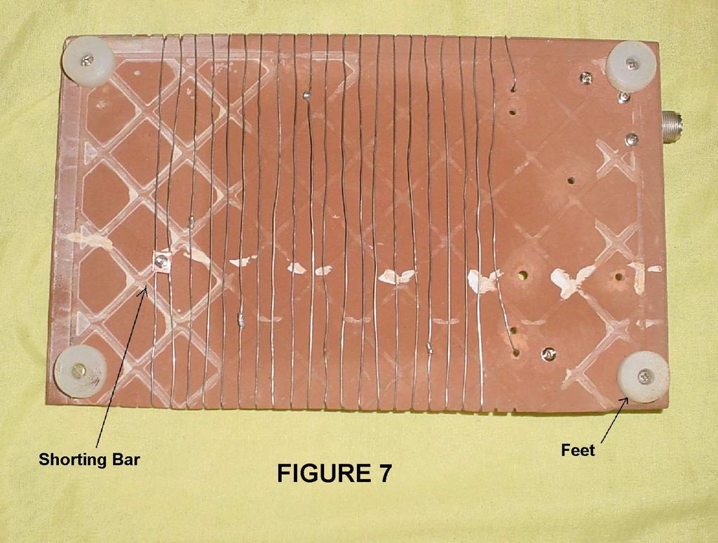
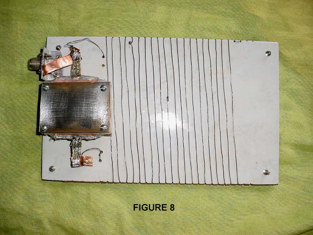
4 Frequency (khz) r (Ω) X (Ω) (equivalent to a 55.12nF capacitor) (equivalent to a 41nH inductor) (equivalent to a 0.37µH inductor) There is no need therefore for retuning of the dummy load when we go through the entire band, though we can do it. Figure 4, however, shows on the vertical line the frequency of kHz (chosen randomly in the band), where the resistive and reactive components are Rs and Xs, this capacitive and equivalent to a capacity Cs. Figure 5 shows the equivalent circuit with the capacitor C inserted and that resonates with X. C r X FIGURE 5 Figure 6 shows the photo of the ceramic plate assembled with the female connector (PL-259) but without the capacitor and Figure 7 its bottom view. For the measurements were used an antenna analyzer model AIM-4170 from Array Solutions, a function generator model MFG-4202 from Minipa (Brazilian) with output impedance equal to 50Ω and an oscilloscope model V-223 from Hitachi. The measurements with the function generator and oscilloscope was based on the fact that, when the load of a non-inductive load is equal to that of the generator, we have a voltage divider by a factor of 2, that is, with the load connected, the voltage must be one half of that of the open circuit (with no load). These results were perfectly confirmed by using the antenna analyzer.
5
6 Figure 8 shows the dummy load ready with its resonance capacitor. The AIM-4170 was used for observe the resonance by adjusting the four bolts of the capacitor (that we see in Figure 8) that adjust its capacity and the shorting bar position that adjusts the resistive component, normally 50Ω on the frequency of interest. It is possible to exist some interaction between both adjusts, that is, after adjusting one parameter, it is possible to trim the other one until the bets result is obtained (this is mainly due the residual existence of a distributed capacitance of the coil). It is important to remember that all adjustments must be done far from metallic surfaces to avoid undesirable interactions that can modify the values of the parameters. Conclusion The presented solution was the construction of a resonant load (narrow band) to replace a high cost high power resistive load (broad band). The usable band of the load, in practice, is far greater than the necessary to cover the band of our interest from 470kHz to 510kHz, especially with the use of a padder capacitor together a shorting bar (the system may be retuned to be adapted to the recently IARU approved kHz band). As our load was mounted with more than one electrical shower resistive devices, because it is cheap and easy to get in the market 5, splices on the wire were necessary. For greater stability, all splices were soldered with tin. For this, it was necessary to scrape the wire ends to be soldered and twist them for mechanical strength and smaller the temperature of the splices to avoid solder melting during real operation. The preparation was made with a special flux (developed for aluminum, but working fine with resistive nickel alloys), from Brasweld (Brazilian) called Alutin. In an electric shower for 220V and 5,500W, that uses the chosen wire, the current is 25A. Under 110V, the current is 43A. With 450W average power (much greater than the 250W of my transmitter), the current would be 3A, therefore the expected temperature for the wire is very low, in special on the splices where the volume is bigger and the heat doesn t jeopardize the tin solders. Appendix The impedance Z of the circuit of Figure 2 is given by: Z = (R + j. ω. L) / (1 - ω 2. L. γ + j. ω. R. γ) This expression can be written as: Z = {R + j. ω. [L. (1 - ω 2. L. γ) R 2. γ]} / [(1 - ω 2. L. γ) 2 + ω 2. R 2. γ 2 ] Taking the resistive r and reactive X components: r = R / [(1 - ω 2. L. γ) 2 + ω 2. R 2. γ 2 ] X = j. ω. [L. (1 - ω 2. L. γ) R 2. γ] / [(1 - ω 2. L. γ) 2 + ω 2. R 2. γ 2 ] When γ is small, we may write: r = R / (1 2. ω 2. L. γ) When expanding the coil increasing its length, γ is a crescent function with L and therefore the expression 1 2. ω 2. L. γ decreases with L, increasing r. So, if only L is varied (with a ferrite) and r varies less than the process of the coil expansion, it means that γ > 0 and is important in the process. 5 The assembling is simpler with the use of 0.75mm diameter nickel-chrome wire got in the market because it has less puckers and doesn t need splices.
Resonant Matching Networks
 Chapter 1 Resonant Matching Networks 1.1 Introduction Frequently power from a linear source has to be transferred into a load. If the load impedance may be adjusted, the maximum power theorem states that
ELECTROMAGNETIC OSCILLATIONS AND ALTERNATING CURRENT
 Chapter 31: ELECTROMAGNETIC OSCILLATIONS AND ALTERNATING CURRENT 1 A charged capacitor and an inductor are connected in series At time t = 0 the current is zero, but the capacitor is charged If T is the
Single Phase Parallel AC Circuits
 Single Phase Parallel AC Circuits 1 Single Phase Parallel A.C. Circuits (Much of this material has come from Electrical & Electronic Principles & Technology by John Bird) n parallel a.c. circuits similar
MODULE-4 RESONANCE CIRCUITS
 Introduction: MODULE-4 RESONANCE CIRCUITS Resonance is a condition in an RLC circuit in which the capacitive and inductive Reactance s are equal in magnitude, there by resulting in purely resistive impedance.
AC Circuits Homework Set
 Problem 1. In an oscillating LC circuit in which C=4.0 μf, the maximum potential difference across the capacitor during the oscillations is 1.50 V and the maximum current through the inductor is 50.0 ma.
Radio Frequency Electronics
 Radio Frequency Electronics Preliminaries III Lee de Forest Born in Council Bluffs, Iowa in 1873 Had 180 patents Invented the vacuum tube that allows for building electronic amplifiers Vacuum tube started
RLC Circuit (3) We can then write the differential equation for charge on the capacitor. The solution of this differential equation is
 We can then write the differential equation for charge on the capacitor. The solution of this differential equation is") RLC Circuit (3) We can then write the differential equation for charge on the capacitor The solution of this differential equation is (damped harmonic oscillation!), where 25 RLC Circuit (4) If we charge
RLC Circuit (3) We can then write the differential equation for charge on the capacitor The solution of this differential equation is (damped harmonic oscillation!), where 25 RLC Circuit (4) If we charge
CHAPTER 22 ELECTROMAGNETIC INDUCTION
 CHAPTER 22 ELECTROMAGNETIC INDUCTION PROBLEMS 47. REASONING AND Using Equation 22.7, we find emf 2 M I or M ( emf 2 ) t ( 0.2 V) ( 0.4 s) t I (.6 A) ( 3.4 A) 9.3 0 3 H 49. SSM REASONING AND From the results
Electromagnetic Oscillations and Alternating Current. 1. Electromagnetic oscillations and LC circuit 2. Alternating Current 3.
 Electromagnetic Oscillations and Alternating Current 1. Electromagnetic oscillations and LC circuit 2. Alternating Current 3. RLC circuit in AC 1 RL and RC circuits RL RC Charging Discharging I = emf R
1 Phasors and Alternating Currents
 Physics 4 Chapter : Alternating Current 0/5 Phasors and Alternating Currents alternating current: current that varies sinusoidally with time ac source: any device that supplies a sinusoidally varying potential
AC Circuits III. Physics 2415 Lecture 24. Michael Fowler, UVa
 AC Circuits III Physics 415 Lecture 4 Michael Fowler, UVa Today s Topics LC circuits: analogy with mass on spring LCR circuits: damped oscillations LCR circuits with ac source: driven pendulum, resonance.
Supplemental Notes on Complex Numbers, Complex Impedance, RLC Circuits, and Resonance
 Supplemental Notes on Complex Numbers, Complex Impedance, RLC Circuits, and Resonance Complex numbers Complex numbers are expressions of the form z = a + ib, where both a and b are real numbers, and i
Physics 240 Fall 2005: Exam #3 Solutions. Please print your name: Please list your discussion section number: Please list your discussion instructor:
 Physics 4 Fall 5: Exam #3 Solutions Please print your name: Please list your discussion section number: Please list your discussion instructor: Form #1 Instructions 1. Fill in your name above. This will
Physics 4B Chapter 31: Electromagnetic Oscillations and Alternating Current
 Physics 4B Chapter 31: Electromagnetic Oscillations and Alternating Current People of mediocre ability sometimes achieve outstanding success because they don't know when to quit. Most men succeed because
Alternating Current Circuits
 Alternating Current Circuits AC Circuit An AC circuit consists of a combination of circuit elements and an AC generator or source. The output of an AC generator is sinusoidal and varies with time according
Pre-Lab. Introduction
 Pre-Lab Read through this entire lab. Perform all of your calculations (calculated values) prior to making the required circuit measurements. You may need to measure circuit component values to obtain
Capacitor. Capacitor (Cont d)
") 1 2 1 Capacitor Capacitor is a passive two-terminal component storing the energy in an electric field charged by the voltage across the dielectric. Fixed Polarized Variable Capacitance is the ratio of
1 2 1 Capacitor Capacitor is a passive two-terminal component storing the energy in an electric field charged by the voltage across the dielectric. Fixed Polarized Variable Capacitance is the ratio of
Impedance and Loudspeaker Parameter Measurement
 ECEN 2260 Circuits/Electronics 2 Spring 2007 2-26-07 P. Mathys Impedance and Loudspeaker Parameter Measurement 1 Impedance Measurement Many elements from which electrical circuits are built are two-terminal
RLC Series Circuit. We can define effective resistances for capacitors and inductors: 1 = Capacitive reactance:
 RLC Series Circuit In this exercise you will investigate the effects of changing inductance, capacitance, resistance, and frequency on an RLC series AC circuit. We can define effective resistances for
MAGNETIC FIELDS & UNIFORM PLANE WAVES
 MAGNETIC FIELDS & UNIFORM PLANE WAVES Name Section Multiple Choice 1. (8 Pts) 2. (8 Pts) 3. (8 Pts) 4. (8 Pts) 5. (8 Pts) Notes: 1. In the multiple choice questions, each question may have more than one
Circuit Analysis-II. Circuit Analysis-II Lecture # 5 Monday 23 rd April, 18
 Circuit Analysis-II Capacitors in AC Circuits Introduction ü The instantaneous capacitor current is equal to the capacitance times the instantaneous rate of change of the voltage across the capacitor.
Assessment Schedule 2015 Physics: Demonstrate understanding of electrical systems (91526)
") NCEA Level 3 Physics (91526) 2015 page 1 of 6 Assessment Schedule 2015 Physics: Demonstrate understanding of electrical systems (91526) Evidence Q Evidence Achievement Achievement with Merit Achievement
NCEA Level 3 Physics (91526) 2015 page 1 of 6 Assessment Schedule 2015 Physics: Demonstrate understanding of electrical systems (91526) Evidence Q Evidence Achievement Achievement with Merit Achievement
The Farad is a very big unit so the following subdivisions are used in
 Passages in small print are for interest and need not be learnt for the R.A.E. Capacitance Consider two metal plates that are connected to a battery. The battery removes a few electrons from plate "A"
Ch. 23 Electromagnetic Induction, AC Circuits, And Electrical Technologies
 Ch. 23 Electromagnetic Induction, AC Circuits, And Electrical Technologies Induced emf - Faraday s Experiment When a magnet moves toward a loop of wire, the ammeter shows the presence of a current When
mywbut.com Lesson 16 Solution of Current in AC Parallel and Seriesparallel
 esson 6 Solution of urrent in Parallel and Seriesparallel ircuits n the last lesson, the following points were described:. How to compute the total impedance/admittance in series/parallel circuits?. How
Physics 405/505 Digital Electronics Techniques. University of Arizona Spring 2006 Prof. Erich W. Varnes
 Physics 405/505 Digital Electronics Techniques University of Arizona Spring 2006 Prof. Erich W. Varnes Administrative Matters Contacting me I will hold office hours on Tuesday from 1-3 pm Room 420K in
Power System Analysis Prof. A. K. Sinha Department of Electrical Engineering Indian Institute of Technology, Kharagpur
 Power System Analysis Prof. A. K. Sinha Department of Electrical Engineering Indian Institute of Technology, Kharagpur Lecture - 9 Transmission Line Steady State Operation Welcome to lesson 9, in Power
y(d) = j
 = j") Problem 2.66 A 0-Ω transmission line is to be matched to a computer terminal with Z L = ( j25) Ω by inserting an appropriate reactance in parallel with the line. If f = 800 MHz and ε r = 4, determine the
Problem 2.66 A 0-Ω transmission line is to be matched to a computer terminal with Z L = ( j25) Ω by inserting an appropriate reactance in parallel with the line. If f = 800 MHz and ε r = 4, determine the
SINUSOIDAL STEADY STATE CIRCUIT ANALYSIS
 SINUSOIDAL STEADY STATE CIRCUIT ANALYSIS 1. Introduction A sinusoidal current has the following form: where I m is the amplitude value; ω=2 πf is the angular frequency; φ is the phase shift. i (t )=I m.sin
EXPERIMENT 07 TO STUDY DC RC CIRCUIT AND TRANSIENT PHENOMENA
 EXPERIMENT 07 TO STUDY DC RC CIRCUIT AND TRANSIENT PHENOMENA DISCUSSION The capacitor is a element which stores electric energy by charging the charge on it. Bear in mind that the charge on a capacitor
What s Your (real or imaginary) LCR IQ?
 LCR IQ?") Chroma Systems Solutions, Inc. What s Your (real or imaginary) LCR IQ? 11021, 11025 LCR Meter Keywords:. Impedance, Inductance, Capacitance, Resistance, Admittance, Conductance, Dissipation Factor, 4-Terminal
Chroma Systems Solutions, Inc. What s Your (real or imaginary) LCR IQ? 11021, 11025 LCR Meter Keywords:. Impedance, Inductance, Capacitance, Resistance, Admittance, Conductance, Dissipation Factor, 4-Terminal
Consider a simple RC circuit. We might like to know how much power is being supplied by the source. We probably need to find the current.
 AC power Consider a simple RC circuit We might like to know how much power is being supplied by the source We probably need to find the current R 10! R 10! is VS Vmcosωt Vm 10 V f 60 Hz V m 10 V C 150
Electric Machines I Three Phase Induction Motor. Dr. Firas Obeidat
 Electric Machines I Three Phase Induction Motor Dr. Firas Obeidat 1 Table of contents 1 General Principles 2 Construction 3 Production of Rotating Field 4 Why Does the Rotor Rotate 5 The Slip and Rotor
General Physics (PHY 2140)
") General Physics (PHY 2140) Lecture 10 6/12/2007 Electricity and Magnetism Induced voltages and induction Self-Inductance RL Circuits Energy in magnetic fields AC circuits and EM waves Resistors, capacitors
General Physics (PHY 2140) Lecture 10 6/12/2007 Electricity and Magnetism Induced voltages and induction Self-Inductance RL Circuits Energy in magnetic fields AC circuits and EM waves Resistors, capacitors
Core Technology Group Application Note 3 AN-3
 Measuring Capacitor Impedance and ESR. John F. Iannuzzi Introduction In power system design, capacitors are used extensively for improving noise rejection, lowering power system impedance and power supply
General Physics II (PHYS 104) Exam 2: March 21, 2002
 Exam 2: March 21, 2002") General Physics II (PHYS 104) Exam 2: March 21, 2002 Name: Multiple Choice (3 points each): Answer the following multiple choice questions. Clearly circle the response (or responses) that provides the
General Physics II (PHYS 104) Exam 2: March 21, 2002 Name: Multiple Choice (3 points each): Answer the following multiple choice questions. Clearly circle the response (or responses) that provides the
Chapter 33. Alternating Current Circuits
 Chapter 33 Alternating Current Circuits 1 Capacitor Resistor + Q = C V = I R R I + + Inductance d I Vab = L dt AC power source The AC power source provides an alternative voltage, Notation - Lower case
Electricity and Light Pre Lab Questions
 Electricity and Light Pre Lab Questions The pre lab questions can be answered by reading the theory and procedure for the related lab. You are strongly encouraged to answers these questions on your own.
3 The non-linear elements
 3.1 Introduction The inductor and the capacitor are the two important passive circuit elements which have the ability to store and deliver finite amount of energy [49]. In an inductor, the energy is stored
ELECTRO MAGNETIC INDUCTION
 ELECTRO MAGNETIC INDUCTION 1) A Circular coil is placed near a current carrying conductor. The induced current is anti clock wise when the coil is, 1. Stationary 2. Moved away from the conductor 3. Moved
RADIO AMATEUR EXAM GENERAL CLASS
 RAE-Lessons by 4S7VJ 1 CHAPTER- 2 RADIO AMATEUR EXAM GENERAL CLASS By 4S7VJ 2.1 Sine-wave If a magnet rotates near a coil, an alternating e.m.f. (a.c.) generates in the coil. This e.m.f. gradually increase
To investigate further the series LCR circuit, especially around the point of minimum impedance. 1 Electricity & Electronics Constructor EEC470
 Series esonance OBJECTIE To investigate further the series LC circuit, especially around the point of minimum impedance. EQUIPMENT EQUIED Qty Apparatus Electricity & Electronics Constructor EEC470 Basic
Chapter 3: Capacitors, Inductors, and Complex Impedance
 hapter 3: apacitors, Inductors, and omplex Impedance In this chapter we introduce the concept of complex resistance, or impedance, by studying two reactive circuit elements, the capacitor and the inductor.
Physics 240 Fall 2005: Exam #3. Please print your name: Please list your discussion section number: Please list your discussion instructor:
 Physics 240 Fall 2005: Exam #3 Please print your name: Please list your discussion section number: Please list your discussion instructor: Form #1 Instructions 1. Fill in your name above 2. This will be
MAY/JUNE 2006 Question & Model Answer IN BASIC ELECTRICITY 194
 MAY/JUNE 2006 Question & Model Answer IN BASIC ELECTRICITY 194 Question 1 (a) List three sources of heat in soldering (b) state the functions of flux in soldering (c) briefly describe with aid of diagram
THE EFFECT OF DIELECTRIC INSIDE AN INDUCTANCE COIL
 THE EFFECT OF DIELECTRIC INSIDE AN INDUCTANCE COIL Inductance coils are often wound around an insulating former which then provides mechanical support. The magnetic field is not affected by this former
What happens when things change. Transient current and voltage relationships in a simple resistive circuit.
 Module 4 AC Theory What happens when things change. What you'll learn in Module 4. 4.1 Resistors in DC Circuits Transient events in DC circuits. The difference between Ideal and Practical circuits Transient
Slide 1 / 26. Inductance by Bryan Pflueger
 Slide 1 / 26 Inductance 2011 by Bryan Pflueger Slide 2 / 26 Mutual Inductance If two coils of wire are placed near each other and have a current passing through them, they will each induce an emf on one
Proceedings of the 13th WSEAS International Conference on CIRCUITS
 About some FACTS devices from the power systems MARICEL ADAM, ADRIAN BARABOI, CATALIN PANCU Power Systems Department, Faculty of Electrical Engineering Gh. Asachi Technical University 51-53, D. Mangeron,
Electrical Circuits Lab Series RC Circuit Phasor Diagram
 Electrical Circuits Lab. 0903219 Series RC Circuit Phasor Diagram - Simple steps to draw phasor diagram of a series RC circuit without memorizing: * Start with the quantity (voltage or current) that is
Alternating Current. Symbol for A.C. source. A.C.
 Alternating Current Kirchoff s rules for loops and junctions may be used to analyze complicated circuits such as the one below, powered by an alternating current (A.C.) source. But the analysis can quickly
Assessment Schedule 2016 Physics: Demonstrate understanding electrical systems (91526)
") NCEA evel 3 Physics (91526) 2016 page 1 of 5 Assessment Schedule 2016 Physics: Demonstrate understanding electrical systems (91526) Evidence Statement NØ N1 N 2 A 3 A 4 M 5 M 6 E 7 E 8 0 1A 2A 3A 4A or
NCEA evel 3 Physics (91526) 2016 page 1 of 5 Assessment Schedule 2016 Physics: Demonstrate understanding electrical systems (91526) Evidence Statement NØ N1 N 2 A 3 A 4 M 5 M 6 E 7 E 8 0 1A 2A 3A 4A or
Capacitors. Charging a Capacitor. Charge and Capacitance. L05: Capacitors and Inductors
 L05: Capacitors and Inductors 50 Capacitors 51 Outline of the lecture: Capacitors and capacitance. Energy storage. Capacitance formula. Types of capacitors. Inductors and inductance. Inductance formula.
EE 242 EXPERIMENT 8: CHARACTERISTIC OF PARALLEL RLC CIRCUIT BY USING PULSE EXCITATION 1
 EE 242 EXPERIMENT 8: CHARACTERISTIC OF PARALLEL RLC CIRCUIT BY USING PULSE EXCITATION 1 PURPOSE: To experimentally study the behavior of a parallel RLC circuit by using pulse excitation and to verify that
How to measure complex impedance at high frequencies where phase measurement is unreliable.
 Objectives In this course you will learn the following Various applications of transmission lines. How to measure complex impedance at high frequencies where phase measurement is unreliable. How and why
Chapter 32A AC Circuits. A PowerPoint Presentation by Paul E. Tippens, Professor of Physics Southern Polytechnic State University
 Chapter 32A AC Circuits A PowerPoint Presentation by Paul E. Tippens, Professor of Physics Southern Polytechnic State University 2007 Objectives: After completing this module, you should be able to: Describe
Laboratory I: Impedance
 Physics 33, Fall 2008 ab I - Exercises aboratory I: Impedance eading: ab handout Simpson hapter if necessary) & hapter 2 particularly 2.9-2.3) ab Exercises. Part I What is the input impedance of the oscilloscope
Driven RLC Circuits Challenge Problem Solutions
 Driven LC Circuits Challenge Problem Solutions Problem : Using the same circuit as in problem 6, only this time leaving the function generator on and driving below resonance, which in the following pairs
1000 to pf (E3 series) Dielectric material K2000 K5000 K14000 Rated DC voltage 100 V 100 V 63 V Tolerance on capacitance ±10% 20/+50% 20/+80%
 Dielectric material K2000 K5000 K14000 Rated DC voltage 100 V 100 V 63 V Tolerance on capacitance ±10% 20/+50% 20/+80%") , Class 2, 63,, V and 1 V (DC) handbook, 4 columns FEATURES General purpose Coupling and decoupling Space saving. APPLICATIONS In electronic circuits where non-linear change of capacitance with temperature
, Class 2, 63,, V and 1 V (DC) handbook, 4 columns FEATURES General purpose Coupling and decoupling Space saving. APPLICATIONS In electronic circuits where non-linear change of capacitance with temperature
Impedance/Reactance Problems
 Impedance/Reactance Problems. Consider the circuit below. An AC sinusoidal voltage of amplitude V and frequency ω is applied to the three capacitors, each of the same capacitance C. What is the total reactance
An example of answers for the final report of Electronics"
 An example of answers for the final report of Electronics" Shingo Katsumoto February 7, 07 Here is an example of answers. There are many other possibilities. DA conversion circuits. Resistance-ladder type
AC Source and RLC Circuits
 X X L C = 2π fl = 1/2π fc 2 AC Source and RLC Circuits ( ) 2 Inductive reactance Capacitive reactance Z = R + X X Total impedance L C εmax Imax = Z XL XC tanφ = R Maximum current Phase angle PHY2054: Chapter
Chapter 30. Inductance
 Chapter 30 Inductance Self Inductance When a time dependent current passes through a coil, a changing magnetic flux is produced inside the coil and this in turn induces an emf in that same coil. This induced
Module 4. Single-phase AC circuits. Version 2 EE IIT, Kharagpur
 Module 4 Single-phase circuits ersion EE T, Kharagpur esson 6 Solution of urrent in Parallel and Seriesparallel ircuits ersion EE T, Kharagpur n the last lesson, the following points were described:. How
LCR Series Circuits. AC Theory. Introduction to LCR Series Circuits. Module. What you'll learn in Module 9. Module 9 Introduction
 Module 9 AC Theory LCR Series Circuits Introduction to LCR Series Circuits What you'll learn in Module 9. Module 9 Introduction Introduction to LCR Series Circuits. Section 9.1 LCR Series Circuits. Amazing
a. Clockwise. b. Counterclockwise. c. Out of the board. d. Into the board. e. There will be no current induced in the wire
 Physics 1B Winter 2012: Final Exam For Practice Version A 1 Closed book. No work needs to be shown for multiple-choice questions. The first 10 questions are the makeup Quiz. The remaining questions are
Power Factor Improvement
 Salman bin AbdulazizUniversity College of Engineering Electrical Engineering Department EE 2050Electrical Circuit Laboratory Power Factor Improvement Experiment # 4 Objectives: 1. To introduce the concept
Chapter 21 Lecture Notes
 Chapter 21 Lecture Notes Physics 2424 - Strauss Formulas: Φ = BA cosφ E = -N Φ/ t Faraday s Law E = Bvl E = NABω sinωt M = (N 2 Φ 2 )/I 1 E 2 = -M I 1 / t L = NΦ/I E = -L I/ t L = µ 0 n 2 A l Energy =
NMR Instrumentation BCMB/CHEM Biomolecular NMR
 NMR Instrumentation BCMB/CHEM 8190 Biomolecular NMR Instrumental Considerations - Block Diagram of an NMR Spectrometer Magnet Sample B 0 Lock Probe Receiver Computer Transmit Superconducting Magnet systems
PROBLEMS TO BE SOLVED IN CLASSROOM
 PROLEMS TO E SOLVED IN LSSROOM Unit 0. Prerrequisites 0.1. Obtain a unit vector perpendicular to vectors 2i + 3j 6k and i + j k 0.2 a) Find the integral of vector v = 2xyi + 3j 2z k along the straight
Alternating Current Circuits. Home Work Solutions
 Chapter 21 Alternating Current Circuits. Home Work s 21.1 Problem 21.11 What is the time constant of the circuit in Figure (21.19). 10 Ω 10 Ω 5.0 Ω 2.0µF 2.0µF 2.0µF 3.0µF Figure 21.19: Given: The circuit
EXP. NO. 3 Power on (resistive inductive & capacitive) load Series connection
 load Series connection") OBJECT: To examine the power distribution on (R, L, C) series circuit. APPARATUS 1-signal function generator 2- Oscilloscope, A.V.O meter 3- Resisters & inductor &capacitor THEORY the following form for
OBJECT: To examine the power distribution on (R, L, C) series circuit. APPARATUS 1-signal function generator 2- Oscilloscope, A.V.O meter 3- Resisters & inductor &capacitor THEORY the following form for
Lecture 4: R-L-C Circuits and Resonant Circuits
 Lecture 4: R-L-C Circuits and Resonant Circuits RLC series circuit: What's V R? Simplest way to solve for V is to use voltage divider equation in complex notation: V X L X C V R = in R R + X C + X L L
Sinusoidal Response of RLC Circuits
 Sinusoidal Response of RLC Circuits Series RL circuit Series RC circuit Series RLC circuit Parallel RL circuit Parallel RC circuit R-L Series Circuit R-L Series Circuit R-L Series Circuit Instantaneous
Electrical Engineering Fundamentals for Non-Electrical Engineers
 Electrical Engineering Fundamentals for Non-Electrical Engineers by Brad Meyer, PE Contents Introduction... 3 Definitions... 3 Power Sources... 4 Series vs. Parallel... 9 Current Behavior at a Node...
Power and Energy Measurement
 Power and Energy Measurement EIE 240 Electrical and Electronic Measurement April 24, 2015 1 Work, Energy and Power Work is an activity of force and movement in the direction of force (Joules) Energy is
The Basic Capacitor. Dielectric. Conductors
 Chapter 9 The Basic Capacitor Capacitors are one of the fundamental passive components. In its most basic form, it is composed of two conductive plates separated by an insulating dielectric. The ability
INTC 1307 Instrumentation Test Equipment Teaching Unit 6 AC Bridges
 IHLAN OLLEGE chool of Engineering & Technology ev. 0 W. lonecker ev. (8/6/0) J. Bradbury INT 307 Instrumentation Test Equipment Teaching Unit 6 A Bridges Unit 6: A Bridges OBJETIVE:. To explain the operation
Design of Narrow Band Filters Part 2
 E.U.I.T. Telecomunicación 200, Madrid, Spain, 27.09 30.09.200 Design of Narrow Band Filters Part 2 Thomas Buch Institute of Communications Engineering University of Rostock Th. Buch, Institute of Communications
ECE 325 Electric Energy System Components 5 Transmission Lines. Instructor: Kai Sun Fall 2015
 ECE 325 Electric Energy System Components 5 Transmission Lines Instructor: Kai Sun Fall 2015 1 Content (Materials are from Chapter 25) Overview of power lines Equivalent circuit of a line Voltage regulation
EE221 Circuits II. Chapter 14 Frequency Response
 EE22 Circuits II Chapter 4 Frequency Response Frequency Response Chapter 4 4. Introduction 4.2 Transfer Function 4.3 Bode Plots 4.4 Series Resonance 4.5 Parallel Resonance 4.6 Passive Filters 4.7 Active
Name: Class: Date: Multiple Choice Identify the letter of the choice that best completes the statement or answers the question.
 Name: Class: Date: AP REVIEW 4 Multiple Choice Identify the letter of the choice that best completes the statement or answers the question. 1. If a positively charged glass rod is used to charge a metal
Unit 21 Capacitance in AC Circuits
 Unit 21 Capacitance in AC Circuits Objectives: Explain why current appears to flow through a capacitor in an AC circuit. Discuss capacitive reactance. Discuss the relationship of voltage and current in
Voltage vs. Current in a Resistor, Capacitor or Inductor
 Voltage vs. Current in a Resistor, Capacitor or Inductor Voltage vs. Current in a Resistor, Capacitor or Inductor Elements in an electrical system behave differently if they are exposed to direct current
Outline. Week 5: Circuits. Course Notes: 3.5. Goals: Use linear algebra to determine voltage drops and branch currents.
 Outline Week 5: Circuits Course Notes: 3.5 Goals: Use linear algebra to determine voltage drops and branch currents. Components in Resistor Networks voltage source current source resistor Components in
Lecture 5: Using electronics to make measurements
 Lecture 5: Using electronics to make measurements As physicists, we re not really interested in electronics for its own sake We want to use it to measure something often, something too small to be directly
Content courtesy of Wikipedia.org. David Harrison, CEO/Design Engineer for Model Sounds Inc.
 Content courtesy of Wikipedia.org David Harrison, CEO/Design Engineer for Model Sounds Inc. Common Capacitor Specs. Capacitance Tolerance Maximum Operating Voltage Less Common Capacitor Specs. Equivalent
EE221 Circuits II. Chapter 14 Frequency Response
 EE22 Circuits II Chapter 4 Frequency Response Frequency Response Chapter 4 4. Introduction 4.2 Transfer Function 4.3 Bode Plots 4.4 Series Resonance 4.5 Parallel Resonance 4.6 Passive Filters 4.7 Active
Solutions to PHY2049 Exam 2 (Nov. 3, 2017)
") Solutions to PHY2049 Exam 2 (Nov. 3, 207) Problem : In figure a, both batteries have emf E =.2 V and the external resistance R is a variable resistor. Figure b gives the electric potentials V between the
Solutions to PHY2049 Exam 2 (Nov. 3, 207) Problem : In figure a, both batteries have emf E =.2 V and the external resistance R is a variable resistor. Figure b gives the electric potentials V between the
Determining Characteristic Impedance and Velocity of Propagation by Measuring the Distributed Capacitance and Inductance of a Line
 Exercise 2-1 Determining Characteristic Impedance and Velocity EXERCISE OBJECTIVES Upon completion of this exercise, you will know how to measure the distributed capacitance and distributed inductance
Lecture 9 Time Domain vs. Frequency Domain
 . Topics covered Lecture 9 Time Domain vs. Frequency Domain (a) AC power in the time domain (b) AC power in the frequency domain (c) Reactive power (d) Maximum power transfer in AC circuits (e) Frequency
Short Wire Antennas: A Simplified Approach Part I: Scaling Arguments. Dan Dobkin version 1.0 July 8, 2005
 Short Wire Antennas: A Simplified Approach Part I: Scaling Arguments Dan Dobkin version 1.0 July 8, 2005 0. Introduction: How does a wire dipole antenna work? How do we find the resistance and the reactance?
04 Matching Networks. Dipl.-Ing. Dr. Michael Gebhart, MSc
 04 Matching Networks 4th unit in course 3, F Basics and omponents ipl.-ing. r. Michael Gebhart, Mc FI Qualification Network, University of pplied ciences, ampus W 013/14, eptember 30 th ontent Introduction:
Laboratory I: Impedance
 Physics 331, Fall 2008 Lab I - Handout 1 Laboratory I: Impedance Reading: Simpson Chapter 1 (if necessary) & Chapter 2 (particularly 2.9-2.13) 1 Introduction In this first lab we review the properties
CLUSTER LEVEL WORK SHOP
 CLUSTER LEVEL WORK SHOP SUBJECT PHYSICS QUESTION BANK (ALTERNATING CURRENT ) DATE: 0/08/06 What is the phase difference between the voltage across the inductance and capacitor in series AC circuit? Ans.
BASIC ELECTRONICS PROF. T.S. NATARAJAN DEPT OF PHYSICS IIT MADRAS LECTURE-3 ELECTRONIC DEVICES -II RESISTOR SERIES & PARALLEL
 BASIC ELECTRONICS PROF. T.S. NATARAJAN DEPT OF PHYSICS IIT MADRAS LECTURE-3 ELECTRONIC DEVICES -II RESISTOR SERIES & PARALLEL Hello everybody we are doing a course on basic electronics by the method of
R-L-C Circuits and Resonant Circuits
 P517/617 Lec4, P1 R-L-C Circuits and Resonant Circuits Consider the following RLC series circuit What's R? Simplest way to solve for is to use voltage divider equation in complex notation. X L X C in 0
HOW TO SOLVE YOUR ANTENNA MATCHING PROBLEMS
 HOW TO SOLVE YOUR ANTENNA MATCHING PROBLEMS John Sexton, G4CNN. Reprinted from Echelford Amateur Radio Society Newsletter for November 1978. Introduction. In January 1977 there appeared in RADCOM an article
AC Circuit. a) Learn the usage of frequently used AC instrument equipment (AC voltmeter, AC ammeter, power meter).
 Learn the usage of frequently used AC instrument equipment (AC voltmeter, AC ammeter, power meter).") Experiment 5:Measure the Equivalent arameters in the AC Circuit 1. urpose a) Learn the usage of frequently used AC instrument equipment (AC voltmeter, AC ammeter, power meter). b) Know the basic operational
Experiment 5:Measure the Equivalent arameters in the AC Circuit 1. urpose a) Learn the usage of frequently used AC instrument equipment (AC voltmeter, AC ammeter, power meter). b) Know the basic operational
PHYS 1441 Section 001 Lecture #23 Monday, Dec. 4, 2017
 PHYS 1441 Section 1 Lecture #3 Monday, Dec. 4, 17 Chapter 3: Inductance Mutual and Self Inductance Energy Stored in Magnetic Field Alternating Current and AC Circuits AC Circuit W/ LRC Chapter 31: Maxwell