Attachment 3: Fragility Curve Determinations DRAFT
|
|
|
- Ronald Riley
- 5 years ago
- Views:
Transcription
1 Attachment 3: Fragility Curve Determinations DRAFT
2 CELRC-TS-DG 4 October 2017 MEMORANDUM FOR PM-PL SUBJECT: Fragility Curve Determination for McCook Levee North and South of 47 th Street Introduction 1. The McCook Levee is an existing levee being considered for repair by USACE. A fragility curve was developed by TS-DG (memo dated 16 November 2016) for the existing levee south of 47 th Street based on the riverside erosion and how it may affect the sheetpile within the levee. 2. However, the levee north of 47 th Street does not have sheetpile and would therefore not have the same vulnerability. To account for the different levee cross section, this memo was completed to determine a new fragility curve which applies to the existing McCook Levee north of 47 th Street, only. 3. Additionally, this memo establishes a range of fragility curves for both sections of levee based on previous iterations. By picking low failure likelihoods and high failure likelihoods. South of 47 th Street Summary 4. The memo dated 16 November 2016 identified the below recommended Probable Failure Point (PFP) and Probable Non-failure Point (PNP) based on stability analyses of the sheetpile within the eroded levee. It also shows historical PFP and PNP elevations. Additional information can be found in the referenced documents. 5. However, based on new survey information, the lowest top of levee elevation is actually ft NAVD88. This is a depression just south of the railroad lines. Therefore, the PFP has been revised to reflect this discovery s FID 24 August November New Feasibility Elevations (ft Memo 2016 Memo Recommended Elevations (ft NAVD88) Elevations (ft Elevations (ft Elevations (ft NGVD29) NAVD88) NAVD88) NAVD88) PFP PNP Figure 1. Revised PFP and PNP Elevations for the McCook Levee south of 47 th Street DRAFT


3 Figure 2: Cross section of PFP and PNP elevations south of 47 th Street Field Observations North of 47 th Street 6. A field visit was completed on 14 November 2016 by Dan Ferris and Justin Griffeth to walk the levee north of 47 th Street. As shown in the photo below, the crest of the levee has an asphalt bike path and wooden fence on the riverside. The slopes of the levee are covered in vegetation and some mature trees. The landside toe was investigated for features such as culverts, encroachments, etc. but none were identified. The date of construction is unknown, and there are no as-built drawings or soil borings available for the levee. RAFT Figure 3: Typical photo of levee north of 47 th St

4 McCook Levee Feasibility Study Fragility Curve North of 47 th St 3 October To determine the heights and dimensions of the levee north of 47 th Street, LiDAR data was used to overlay the aerial image. A screenshot is shown below. Figure 4: Aerial image of levee with LiDAR elevations 8. The cross section below was developed based on the LiDAR data, which shows the levee has a 20+ ft wide crest, 2:1 slopes, and is approximately 8 feet tall on the riverside, and 10 feet tall on the landside.
5 McCook Levee Feasibility Study Fragility Curve North & South of 47 th St 4 October 2017 Figure 5: Drawing of typical cross section north of 47 th St Probable Failure Point Determination 9. The existing levee north of 47 th Street was noted for the high amount of vegetation. This vegetation limited the inspection s ability to note additional deficiencies such as animal burrows, erosion, depressions, etc. although none of these were noted. The vegetation can also increase the risk to the levee, as tree roots create seepage paths through the berm and it makes inspection and flood-fighting during events difficult. Also, trees can fall over and pull their root wad out of the levee, creating possible instability, seepage, and erosion issues. 10. As measured in from the LiDAR data, the crest width is approximately 20 feet wide at the minimum. EM recommends a minimum crest width of 10 feet. Since the actual crest is about twice the recommended width, the levee does have some resiliency. 11. Since there are no features that increase the risk other than the prevalent vegetation, the PFP is determined to be at the top of the levee, which is about ft NAVD88. At this elevation, the levee would be overtopped and susceptible to erosion of the crest and landside slope, which could fail the levee. DRAFT 12. To determine the PNP elevation, the vegetation present on the slopes was determined to be the controlling factor. Thick vegetation limits the ability for flood-fighting in two ways; to identify an issue and to combat an issue. So while the levee is wider than necessary, issues could arise such as seepage due to unknown fill of the levee, large animal burrows, or fallen/dead trees on the slope. But due to the vegetation, these issues may not be noticed or if they are noticed, they would be difficult to flood-fight during an event. The lowest elevation where homes may be affected is about elevation 596 ft NAVD88 should the levee breach. Therefore, this elevation was chosen as the PNP because this elevation is when flood-fighting activities would start, which may have limited success identifying and combating the issue due to the vegetation. North of 47 th Street (ft NAVD88) PFP PNP 596 Figure 6. PFP and PNP Elevations for the McCook Levee North of 47 th Street

6

7
8 CELRC-TS-DG 16 November 2016 MEMORANDUM FOR PM-PL SUBJECT: Revised Fragility Curve Determination for McCook Levee with respect to Sheetpile Stability Introduction 1. The McCook Levee is an existing levee being considered for repair by USACE. A fragility curve was developed by TS-DG (memo dated 24 August 2016) for the existing levee based on global stability using SLOPE/W and historical floods. It did not take into account the riverside erosion that had been noted but not quantified in previous inspections. 2. Therefore, this memo examines the sheetpile stability with regard to riverside erosion and how that may affect the fragility curve. The vulnerability to the sheetpile is the landside soil load pushes the sheetpile towards the river when water is low and there is no riverside soil to resist. 3. Additionally, the cross section on the drawings was analyzed to ensure that without erosion, the floodwall is acceptable. This was done following ETL using CWALSHT. Field Observations 4. A field visit was completed on 14 November 2016 by Dan Ferris and Justin Griffeth, where the riverside slope was noted to have two locations that show significant erosion. The more extreme case was near Sta where about 11.5 ft of sheetpile was exposed, as measured from the top of sheetpile to exposed toe. Another location near Sta measured about 6 ft of exposed sheetpile. A drawing and photo of the more extreme case is shown below. RAFT Figure 1: Drawing of worst erosion (Sta ) view from river


9 McCook Levee Feasibility Study Revised Fragility Curve Discussion w.r.t. Sheetpile Stability 16 November 2016 Figure 2: Photo of erosion near Sta with 11.5 ft dropoff from top of SSP to exposed toe 5. The less extreme erosion point with a dropoff of about 6 ft is noted for the sandbags along the riverside of the floodwall. It is unknown why these sandbags are here, but it is possible they were placed there to reduce riverside erosion during a flood. RAFT Figure 3: Photo of erosion near Sta with 6 ft dropoff and sandbags

10
11

12 McCook Levee Feasibility Study Revised Fragility Curve Discussion w.r.t. Sheetpile Stability 16 November 2016 Figure 6: Measurement of existing sheetpile, most closely resembles JSP-2 Gap Analysis 11. As part of this memo, it was determined that the sheetpile should be checked against ETL to ensure it would be acceptable once erosion is corrected. If it is not acceptable, then additional cost would have to go into retrofitting the sheetpile that is not currently in the cost estimate. 12. ETL was developed post-hurricane Katrina and describes three failure modes that all floodwalls should be checked against. The first is creation of a flood-side gap in cohesive soils, second is rotational stability failure around the floodwall point considering this gap, and the third is rating the floodwall against criteria for consolidation of deflections. Each of these failure modes are checked in the analysis below. Flood-side Gap DRAFT 13. The flood-side gap is caused when cohesive soils are present on the water side of the floodwall and a high water event occurs. Floodwaters enter the gap which extends to a depth of Z 0 defined below. A stability analysis was completed to determine how the gap filled with water affects the stability of the floodwall. The depth of a potential gap can be defined as Z 0 = 2c/( sat - water ) Z 0 = 2c/( sat - water ) = 2*250/( ) = 8.0 ft 14. Since the total height of the floodwall greater than Z 0 (20 > 8), the potential gap extends just 8 ft below the top of the levee (elevation 592 ft). The tip elevation is 584 ft, so there is 8 ft of active earth pressure acting on the bottom portion. The cross section was drawn without the floodwall and river side soils to determine how a saturated gap would act on the land side soils. A load of 62.4 psf was applied to represent the water, while a load of psf was applied to represent the active earth pressure. The protected side is considered to be completely saturated to be overly conservative. Based on these characteristics, the gap analysis produces a factor of safety of 1.146, which is greater than the recommended 1.0. It is shown below, at Sta Refer to the Fragility Curve Analysis for soil cross section and properties.

13 McCook Levee Feasibility Study Revised Fragility Curve Discussion w.r.t. Sheetpile Stability 16 November 2016 Figure 7: SLOPE/W gap analysis result Rotational Failure 15. To determine the rotational stability of the floodwall, an analysis using CWALSHT was performed using the elevations developed in the gap analysis. The landside soil mass is great enough that the water pressure built up on the riverside does not allow a failure wedge to develop. Refer to the Wall4 run (Ref 3). Deformation/Deflection Failure 16. The final check is based on maximum water levels for a deformation evaluation. The heights are shown on Table B-2 of ETL , extracted below. Figure 8: Table B-2 from ETL DRAFT 17. This floodwall height is elevation ft NAVD88, with a maximum of about 4 feet between the protected side ground and the flood height. The foundation type is I-wall on levee and the protection level is equivalent to the 0.2% chance exceedance level (500-year storm), which equates to a maximum of 4 feet before permanent deflection of the soils occurs. Since that is the maximum height, permanent deflection is not anticipated and the McCook Levee is acceptable for this condition. Conclusion
14 McCook Levee Feasibility Study Revised Fragility Curve Discussion w.r.t. Sheetpile Stability 16 November The McCook Levee sheetpile passes the requirements of ETL , aside from the erosion present on the riverside. Therefore, there will likely not be any additional rehabilitation requirements with respect to the sheetpile than what was originally estimated (tree removal and regrading). 19. Based on the measured erosion height on the riverside and the results of the sensitivity analysis with CWALSHT, the fragility curve established in the memo dated 24 August 2016 is being reevaluated. The CWALSHT analysis establishes an acceptable factor of safety (1.5) is achieved when there is less than 9 feet of sheetpile exposed from top to base. Station has about 11.5 feet of erosion, so there is an increased chance of failure than what would be acceptable. 20. The type of failure expected with loss of riverside slope would occur when water is low, as the sheetpile is more prone to tipping into the river without a water surcharge. Therefore, the PFP will remain as what was previously determined in the prior memo. However, the PNP will be reduced to show the increased risk of erosion on the riverside which would cause instability of the sheetpile wall. The presence of sandbags on the riverside slope (Figure 3) indicate that there may have been previous backfilling. Also, the existing erosion at Sta shows that erosion can extend deep to expose a significant portion of the sheetpile. Any future high water would exacerbate this problem. 21. It is determined that the PNP elevation should be reduced to the level that produces a factor of safety less than 1.5 for wall stability. Each event to this elevation will erode the riverside slope, especially at Sta , increasing the likelihood of failure where sheetpile tips into the river. A chart tracking the PFP and PNP is shown below, as well as, a simple cross section indicating the new elevations s FID Elevations 24 August 2016 New Feasibility (ft NAVD88) Memo Elevations (ft Recommended Elevations (ft NAVD88) Elevations (ft NGVD29) NAVD88) PFP PNP Figure 9. Revised PFP and PNP Elevations for the McCook Levee DRAFT Figure 10: Cross section of PFP and PNP elevations
15 McCook Levee Feasibility Study Revised Fragility Curve Discussion w.r.t. Sheetpile Stability 16 November 2016 References 1. USACE, Chicago District. McCook Levee, McCook, Illinois Feasibility Study, Appendix C Geotechnical Investigation USACE, Chicago District. Fragility Curve determination for McCook Levee. 24 August 2016 S:\LRC-Project\PRJ-205 McCook Levee\TS-DG\McCookLevee Frag Curve docx 3. CWALSHT Run Results: S:\LRC-Project\PRJ-205 McCook Levee\TS-DG\CWALSHT trials DRAFT
16 CELRC-TS-DG 24 August 2016 MEMORANDUM FOR PM-PL SUBJECT: Fragility Curve Determination for McCook Levee Purpose 1) This memorandum was prepared to discuss the fragility curve of the existing McCook Levee. A fragility curve, as defined in EM , Risk-Based Analysis for Flood Damage Reduction Studies is a statistical distribution of levee failure which is used to develop the stage-damage function and description of the overall uncertainty of that function. 2) The fragility curve is defined by determining two points on a graph; the probable failure point (PFP) and probable non-failure point (PNP). The PFP is defined as the water elevation above which the levee is highly likely to fail, set at 85% failure rate in the EM. The PNP is defined as the water elevation below which the levee has a low likelihood of failure, set at 15% failure rate in the EM. Figure 7-4 is extracted from EM to illustrate the fragility curve, as shown below. DR FT Figure 1. Levee failure probability function from EM , Figure 7-4 Levee Background Information 3) The McCook Levee is an existing levee along the Des Plaines River which reduces the risk of flooding in the communities of McCook, Lyons, and Summit, Illinois. It was originally constructed in the early 1900 s as a berm but was breached in After the breach, the levee was repaired and sheetpile was installed to increase the height. Since 1979, the levee has been loaded many times and while there were some instances of noted seepage, the levee has not failed or overtopped. A typical cross section is shown below. 1
 The McCook Levee was part of a feasibility study in the early 1980 s (Reference 1).")
17 McCook Levee Feasibility Study Fragility Curve Discussion 24 August 2016 Figure 2. Typical McCook Levee Cross Section 1980 s PFP and PNP Determination 4) The McCook Levee was part of a feasibility study in the early 1980 s (Reference 1). This study included the development of a fragility curve. Stability analyses with varying riverside water elevations were completed to calculate a range of factors of safety. This found that when the river elevation was above ft NGVD29, the factor of safety dropped below 1.4, which is the recommended minimum for steady-state seepage per EM Therefore, ft NGVD29 was determined to be the PFP. The PNP was assigned elevation ft NGVD29, which is roughly the 1.0 ACE flood. DRA T 5) This 1980 s analysis effectively ignored the seepage cutoff abilities of the sheetpile that was installed in 1979 to be conservative. However by ignoring the effectiveness, the resulting PFP and PNP are very low; about 5 and 8 ft below the levee crest, respectively. Therefore, the cross section was reanalyzed with current software to account for the sheetpile cutoff. SLOPE/W Reanalysis 6) A model was recreated to match the dimensions and use the same material properties. Figure 3 below shows the 1980 s model and Figure 4 shows the new one created. Figure 5 includes the soil properties used by both. 2

18
 This model ignores the benefits the sheetpile wall affords.")
19 McCook Levee Feasibility Study Fragility Curve Discussion 24 August ) Running the SLOPE/W model with the high water level resulted in a factor of safety at This is similar to the 1980 s result, which calculated Figure 6. Stability re-run with 1980 s Cross section and phreatic line 8) This model ignores the benefits the sheetpile wall affords. The sheetpile should cut off, or significantly reduce through seepage and lower the phreatic line to the sheetpile toe. Therefore, this case was run, which results in a much higher factor of safety at D AFT Figure 7. Stability run with revised phreatic line accounting for sheetpile 9) Rerunning this analysis with a water level at the top of the sheetpile (elevation ft NAVD88) results in the same factor of safety. Therefore, it does not appear that slope instability would occur on the landside slope when the levee is loaded to the top. 4
. To adjust this gage elevation to the location of McCook Levee, 3 ft is subtracted as shown on the chart provided by MWRD (Column 5 minus Column 12). Figure 8.")
 was checked. In order for the gage readings on the website to be converted to elevations at McCook Levee, the following calculations were completed.")
20 McCook Levee Feasibility Study Fragility Curve Discussion 24 August 2016 Historical Floods 10) Since 1944, the Des Plaines River has had many high water events which are recorded at the Riverside gage (Reference 2). To adjust this gage elevation to the location of McCook Levee, 3 ft is subtracted as shown on the chart provided by MWRD (Column 5 minus Column 12). Figure 8. MWRD Provided Elevation Table of Des Plaines Gage versus McCook Levee D 11) This chart only shows the largest 17 events recorded on the Des Plaines Riverside gage. For additional events, the NOAA page (Reference 2) was checked. In order for the gage readings on the website to be converted to elevations at McCook Levee, the following calculations were completed. (NGVD = NAVD88). Gage 0.00 reading = ft NGVD = ft NAVD88 Subtract 3 from gage location to get elevation at McCook Levee, so ft gage 3 = ft McCook Levee So ft McCook Levee = 0.00 Gage reading 5
21 McCook Levee Feasibility Study Fragility Curve Discussion 24 August ) With this conversion, the following table was created to show the number of events that have exceeded certain elevations at McCook Levee using the Riverside gage historic loads, particularly the ones after the levee was repaired in Flood Elevation (ft NAVD88) Number of Occurrences without failure ( ) Figure 9. Table showing number of historic event exceedances 13) Another calculation was completed to determine the gage height of the hypothetical PFP from the 1980 s report at McCook Levee. For the PFP elevation at ft NGVD29 = ft McCook Levee ft McCook Levee + 3 = ft gage ft gage ft NAVD88 gage 0.00 reading = 5.32 ft Therefore, any gage readings greater than 5.32 ft likely exceed the 1980 s PFP. 14) According to the historical crests (Reference 2), a gage reading of 5.32 ft exceeded the 1980 s PFP 70 times, 33 of which occurred since the 1979 repairs were completed. If levee failure with a probability of 85% didn t occur after 33 occurrences, then the 1980 s PFP is considered overly conservative and not realistic. Revised PFP and PNP DRAFT 15) Since the previous fragility curve is not realistic, a new one must be developed to properly model the probability of levee failure. 16) Additional analysis could be completed on slope stability, but the results from the revised stability analysis above met the minimum factor of safety set by EM Also, since the levee has withstood several high water events it can be assumed that the factor of safety is at least 1 in all cases to this point. 17) The other failure method to calculate is seepage and uplift. Constructing a seepage model would be an effective way to show the various factors of safety while changing the flood levels. 6
22 McCook Levee Feasibility Study Fragility Curve Discussion 24 August 2016 However in this case, the amount of uncertainty in developing such a model would not produce accurate PFP and PNP elevations for the following reasons: a) An accurate survey of the levee is not available, so the contours may not accurately reflect the actual site conditions. There are a few cross sections available in the 1980 s report, but these appear to be idealized without accounting for the ditch on the landside, erosion on the riverside, and are at locations with low seepage concerns. b) All of the borings were completed on the crest of the levee, so any changes in the subsurface at the landside or riverside toes would not be captured. c) Several permeability tests were run during the 1984 subsurface investigation. Within the sand portion between Sta to 45+00, values ranging from 10-2 to 10-5 cm/sec were obtained from falling head tests within the hole. An additional test was attempted at Sta but the permeability was too high to measure. The variation in these measurements make it difficult to model accurately, especially when each varies by several orders of magnitude. Additionally, the permeable zones are not well delineated. d) How the landside ditch is modeled would also affect the results. The more the ditch is filled with water, the less head differential between the land and river sides of the levee. Lower head differential reduces the risk of seepage. During the 2013 event, end-around overtopping occurred which inundated the ditch and may have limited/prevented seepage. This end-around flooding did not occur during the 1986 event when seepage was noted. e) The model cannot take into account features such as the trees prevalent on the levee. Trees provide seepage paths along their root systems, particularly after a tree dies and the roots rot away. 18) With all of this uncertainty, creating a seepage model to determine the risk of seepage and uplift of McCook Levee would be subjected to many different judgement calls. Combining these judgement calls may not represent the actual field condition, especially for the purpose of selecting specific flood elevations for the PFP and PNP. Historical Approach DRAFT 19) Instead of calculating the PFP and PNP via modeling floods, these elevations will be looked at in an historical context. All of the occurrences shown in Figure 9 above did not have a failure of the levee, and the only damage noted to the levee has been minor seepage and riverside erosion. 20) To establish the PNP, the historic loadings were examined. The only record of adverse conditions occurring was some seepage observed in the October 1986 event; which peaked at about 600 ft NAVD88. In general, if seepage has been observed, then subsequent events would require less head to recreate the seepage, as the path has already been established. Therefore, the PNP is determined to be 1 foot lower than the 1986 event, at ft NAVD88. At this elevation, the levee has been loaded about 10 times since the repairs in
23 McCook Levee Feasibility Study Fragility Curve Discussion 24 August ) Historic loadings were also examined to establish the PFP. The levee has been loaded within about 1-½ ft of the crest without major issues 3 times since the repairs in The PFP is defined as the elevation where the levee is 85% likely to fail. Since the McCook Levee has survived these extreme loading events, the elevation where it would likely meet this definition would be the top of the levee. If McCook Levee overtopped, then additional damage would be realized from erosion on the landside and would likely cause levee failure. Therefore, the PFP is determined to be at the levee crest, or ft NAVD88. Summary 22) The original PFP and PNP calculated in the 1980 s feasibility report are overly conservative based on the fact that the analysis ignored the sheetpile to calculate a lower factor of safety than what is likely occurring. Additionally, with an additional 30 years of observations since that report was written, the levee has experienced loading greater than the PFP over 30 times without failure. The new PFP and PNP established by this memo are shown in Figure 10 below s Feasibility Elevations (ft NGVD29) FID Elevations (ft NAVD88) New/Recommended Elevations (ft NAVD88) PFP PNP Figure 10. Revised PFP and PNP Elevations for the McCook Levee 23) It should be noted that these points for the Fragility Curve are based on existing knowledge and field observations. Each subsequent flood event will continue to degrade the levee and lead to more issues with seepage, erosion, and eventually instability and failure. There are three major concerns of the condition of the existing levee: DRAFT a) The riverside slope has experienced significant erosion when compared to the as-built cross section. The sheetpile does not extend much deeper than the base of the levee, so as the riverside slope continues to erode, the sheetpile will lose its embedment and could tip toward the river. b) Seepage was first documented during the 1986 flood and there have been many events after this that probably experienced seepage as well, despite the lack of field observations. In events such as 2013, the high water & vegetation in the ditch likely limited the inspector s ability to document any seepage. Also, the permeability test that was attempted near Sta that could not record a result is an indication that seepage will be a concern. c) The large trees present on the levee also present a significant risk. As trees continue to grow, they are more likely to fall over, which would take a significant root ball and chunk of levee with them. Attachments 8
24 McCook Levee Feasibility Study Fragility Curve Discussion 24 August Plan and Profile View of McCook Levee based on 1979 and 1984 Borings References 1. USACE, Chicago District. McCook Levee, McCook, Illinois Feasibility Study, Appendix C Geotechnical Investigation NOAA, Advanced Hydrologic Prediction Service. Des Plaines River at Riverside. < DRAFT 9
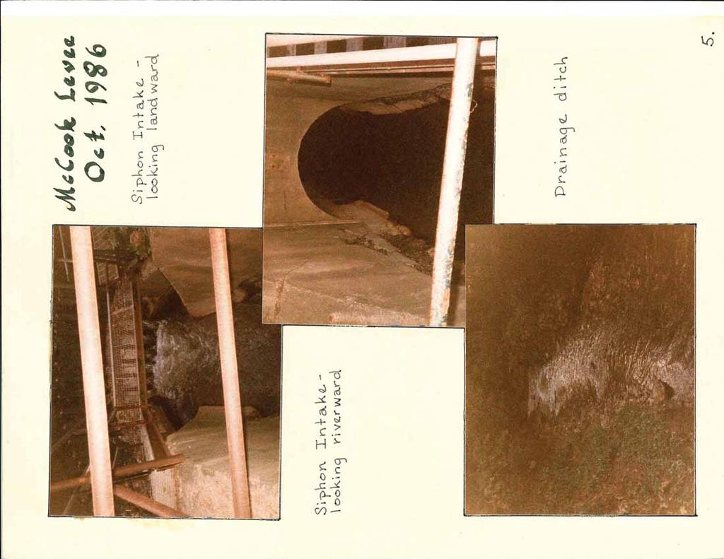
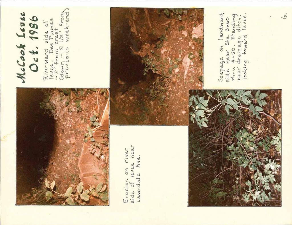
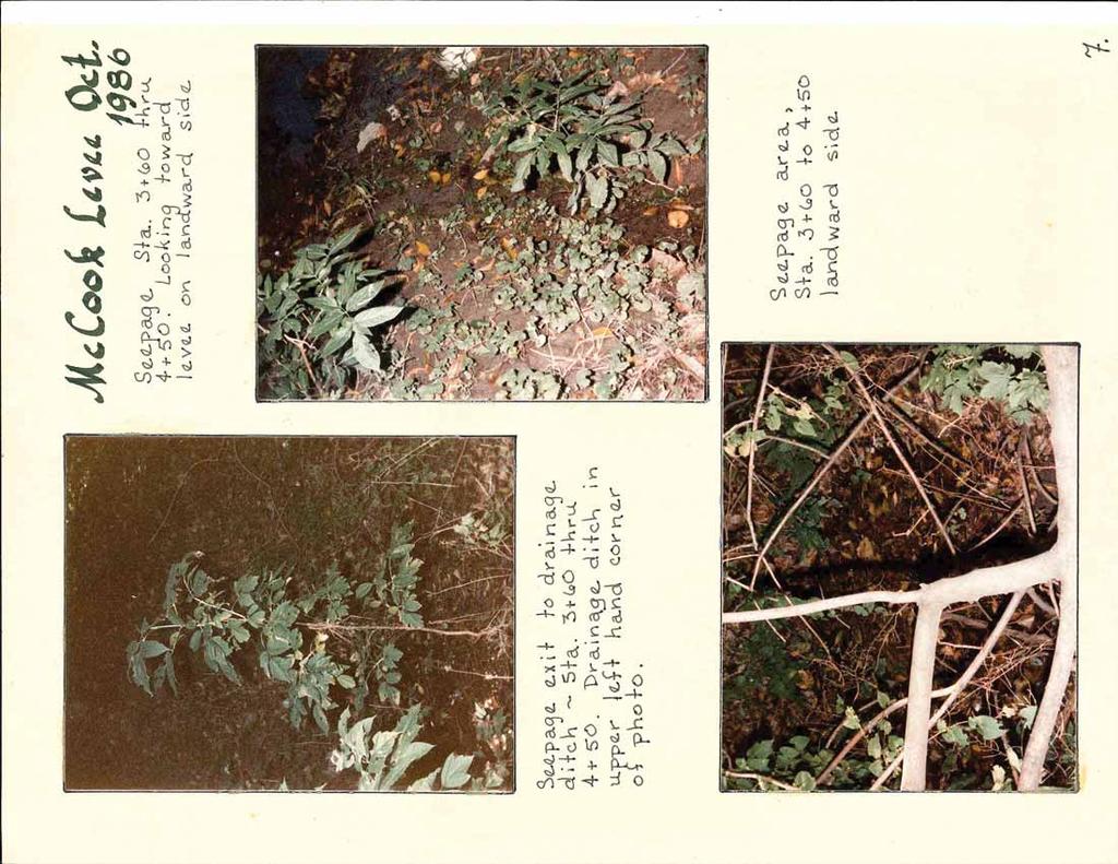
25 Attachment 4: Field Observations and Photos of October 1986 Flood Event DRAFT
26
27
28
29
30
31
32
33

34

35

36

37

38

39
40
41
42

43

44

45

46
47
48
49

50

51

52
Three-Dimensional Seepage Effects at Three New Orleans Levee Breaches During Hurricane Katrina
 Three-Dimensional Seepage Effects at Three New Orleans Levee Breaches During Hurricane Katrina Diego Cobos-Roa Graduate Student Department of Civil & Environmental Engineering University of California
CHAPTER FIVE: THE LOWER MISSISSIPPI REGION AND PLAQUEMINES PARISH
 CHAPTER FIVE: THE LOWER MISSISSIPPI REGION AND PLAQUEMINES PARISH 5.1 Overview Plaquemines Parish is the area where the last portion of the Mississippi River flows out into the Gulf of Mexico (see Figures
HURRICANE SANDY LIMITED REEVALUATION REPORT UNION BEACH, NEW JERSEY DRAFT ENGINEERING APPENDIX SUB APPENDIX A PRELIMINARY FLOODWALL DESIGN
 HURRICANE SANDY LIMITED REEVALUATION REPORT UNION BEACH, NEW JERSEY DRAFT ENGINEERING APPENDIX SUB APPENDIX A PRELIMINARY FLOODWALL DESIGN March 2014Revised March 2015 UNITED STATES ARMY CORPS OF ENGINEERS
IMPORTANCE OF GEOLOGIC CHARACTERIZATION FOR LEVEE FOUNDATION AND BORROW MATERIALS AS STUDIED AT THE INDIAN GRAVES LEVEE DISTRICT, ADAMS COUNTY, IL
 IMPORTANCE OF GEOLOGIC CHARACTERIZATION FOR LEVEE FOUNDATION AND BORROW MATERIALS AS STUDIED AT THE INDIAN GRAVES LEVEE DISTRICT, ADAMS COUNTY, IL Conor Watkins Missouri University of Science and Technology
NEEDLES S STREET LEVEE SYSTEM SAN BERNARDINO COUNTY, CALIFORNIA NLD SYSTEM ID #
 SAN BERNARDINO COUNTY, CALIFORNIA NLD SYSTEM ID # 3805030008 PERIODIC INSPECTION REPORT NO. 1 GENERALIZED EXECUTIVE SUMMARY FINAL SYSTEM RATING: MINIMALLY ACCEPTABLE FINAL RATING DATE: AUGUST 2014 PERIODIC
CHAPTER SEVEN: THE NEW ORLEANS EAST PROTECTED AREA
 7.1 Introduction CHAPTER SEVEN: THE NEW ORLEANS EAST PROTECTED AREA The New Orleans East (NEO) protected area includes some of the lowest ground in the metropolitan region. Therefore, it is not surprising
Appendix 9 Risk Methodology
 Appendix 9 Risk Methodology Introduction This Appendix describes the risk analysis philosophy and methodology used to evaluate the performance of the New Orleans hurricane protection system. Probabilistic
Appendix 15 Computational Methodology
 Appendix 15 Computational Methodology Introduction This Appendix describes the process used by the risk team to determine the final loss exceedence values in the risk analysis. The process involved the
This report was prepared by Klohn Crippen Consultants Ltd. for Alberta Transportation Central Region under Contract No. CE053/2000.
 Alberta Transportation Central Region #401, 4902 51 Street Red Deer, Alberta T4N 6K8 June 7, 2002 Mr. Melvin Mayfield, P.Eng. Project Engineer Dear Mr. Mayfield: Central Region Landslide Assessment Site
Background and Purpose of Meeting. River Towers Meeting. Flood Risk Management Study Alternatives Overview
 1 and Purpose of Meeting River Towers Meeting Flood Risk Management Study Alternatives Overview September 23, 2014 There is no "proposed" flood risk management solution for this area at this time Fairfax
LAR BPWG. DWR Erosion Screening Process Application to LAR. May 17, water resource specialists
 LAR BPWG DWR Erosion Screening Process Application to LAR May 17, 2016 Presentation Outline Review of Erosion Screening Process Modifications for LAR Application ESP LAR Results Recommendations ESP Background
Sacramento River Bank Protection Project
 2005 - FIELD RECONNAISSANCE REPORT OF BANK EROSION SITES - SACRAMENTO RIVER FLOOD CONTROL LEVEES AND TRIBUTARIES Sacramento River Bank Protection Project Project No. 32-0530.10, Task 3 Prepared for: U.S.
CCR Rule Annual Inspection Report (cont.) 2
 2") The inspection findings consisted of maintenance items and items that were not observed to be signs or potential signs of significant structural weakness. No deficiencies or disrupting conditions that
The inspection findings consisted of maintenance items and items that were not observed to be signs or potential signs of significant structural weakness. No deficiencies or disrupting conditions that
SLOSH New Orleans Basin 2012 Update
 SLOSH New Orleans Basin 2012 Update Michael Koziara Science and Operations Officer National Weather Service Slidell, LA The Basics What is storm surge? What is SLOSH? Details Assumptions Inundation = Storm
Evaluation of Storm Tide Measurements at Panama City Beach, FL
 Evaluation of Storm Tide Measurements at Panama City Beach, FL 1993-2007 Prepared by Mark E. Leadon Beaches and Shores Resource Center Florida State University May 2009 Prepared for Florida Department
SAN JACINTO RIVER / BAUTISTA CREEK LEVEE SYSTEM RIVERSIDE COUNTY, CALIFORNIA NLD ID #
 SAN JACINTO RIVER / BAUTISTA CREEK LEVEE SYSTEM RIVERSIDE COUNTY, CALIFORNIA NLD ID # 3805010019 PERIODIC INSPECTION REPORT NO 1 GENERALIZED EXECUTIVE SUMMARY FEBRUARY 2013 FINAL RATING: MINIMALLY ACCEPTABLE
Expert Report. Robert Glenn Bea, Ph.D., P.E.
 Expert Report of Robert Glenn Bea, Ph.D., P.E. Prepared for Plaintiffs in: Katrina Canal Breaches Consolidated Litigation [Civil Action Number: 05-4182 K (2)] United States District Court Eastern District
Saganashkee Slough - McMahon Woods Section 506 Great Lakes Fishery & Ecosystem Restoration Study
 2015 Saganashkee Slough - McMahon Woods Section 506 Great Lakes Fishery & Ecosystem Restoration Study Appendix B Civil Design USACE Chicago District August 2015 TABLE OF CONTENTS INTRODUCTION... 3 General...
Appendix 10 Reliability Modeling
 Appendix 10 Reliability Modeling Reliability analysis is that part of the risk study that leads to an evaluation of the conditional probability of failure (i.e., reliability or fragility) of structures,
Armstrong Case Judgement and Findings of Fact.PDF
 April 12, 2013 Dr. W. Allen Marr, Founder and CEO of Geocomp Corporation, provided pivotal expert witness testimony in the long-standing Hurricane Katrina litigation known as the Armstrong case, which
PROBABILISTIC DESIGN METHOD OF LEVEE AND FLOODWALL HEIGHTS FOR THE HURRICANE PROTECTION SYSTEM IN THE NEW ORLEANS AREA
 PROBABILISTIC DESIGN METHOD OF LEVEE AND FLOODWALL HEIGHTS FOR THE HURRICANE PROTECTION SYSTEM IN THE NEW ORLEANS AREA Mathijs van Ledden Haskoning Inc., 1 Galleria Blvd., Metairie, LA70001, United States,
HURRICANE SANDY LIMITED REEVALUATION REPORT UNION BEACH, NEW JERSEY DRAFT ENGINEERING APPENDIX SUB APPENDIX C SEA LEVEL RISE ANALYSIS
 HURRICANE SANDY LIMITED REEVALUATION REPORT UNION BEACH, NEW JERSEY DRAFT ENGINEERING APPENDIX SUB APPENDIX C SEA LEVEL RISE ANALYSIS Rev. 18 Feb 2015 1.0 Introduction 1.1 Guidance The Department of the
February 18, 2003 File: NORTH CENTRAL REGION LANDSLIDE ASSESSMENT HWY 43:16 WHITECOURT EAST HILL (NC1) 2002 ANNUAL INSPECTION REPORT
 2002 ANNUAL INSPECTION REPORT") February 18, 2003 File: 15-76-11 Alberta Transportation Room 223, Provincial Building 4709 44 Avenue Stony Plain, Alberta T7Z 1N4 Attention: Mr. Rob Lonson, P.Eng. NORTH CENTRAL REGION LANDSLIDE ASSESSMENT
February 18, 2003 File: 15-76-11 Alberta Transportation Room 223, Provincial Building 4709 44 Avenue Stony Plain, Alberta T7Z 1N4 Attention: Mr. Rob Lonson, P.Eng. NORTH CENTRAL REGION LANDSLIDE ASSESSMENT
PART 4 HURRICANE KATRINA STRIKES NEW ORLEANS AUGUST 2005
 PART 4 HURRICANE KATRINA STRIKES NEW ORLEANS AUGUST 2005 Hurricane Katrina Hurricane Katrina swept across southern Florida and lost momentum, then gained speed and water, showing the second lowest barometric
Carmel River Bank Stabilization at Rancho San Carlos Road Project Description and Work Plan March 2018
 Carmel River Bank Stabilization at Rancho San Carlos Road Project Description and Work Plan March 2018 EXISTING CONDITION The proposed Carmel River Bank Stabilization at Rancho San Carlos Road Project
SCOUR CHARACTERIZATION DUE TO WATER FREE FALL
 SCOUR CHARACTERIZATION DUE TO WATER FREE FALL Abdolreza Osouli, Corresponding Author, Ph.D., P.E. Assistant Professor of Civil Engineering, Southern Illinois University at Edwardsville, Engineering Building,
EAGLES NEST AND PIASA ISLANDS
 EAGLES NEST AND PIASA ISLANDS HABITAT REHABILITATION AND ENHANCEMENT PROJECT MADISON AND JERSEY COUNTIES, ILLINOIS ENVIRONMENTAL MANAGEMENT PROGRAM ST. LOUIS DISTRICT FACT SHEET I. LOCATION The proposed
Mount St. Helens Project Cowlitz River Levee Systems 2009 Level of Flood Protection Update Summary
 Mount St. Helens Project Cowlitz River Levee Systems 2009 Level of Flood Protection Update Summary Cowlitz River at Longview/Kelso, Washington February 4, 2010 Executive Summary USACE periodically updates
Slope Stability Evaluation Ground Anchor Construction Area White Point Landslide San Pedro District Los Angeles, California.
 Slope Stability Evaluation Ground Anchor Construction Area White Point Landslide San Pedro District Los Angeles, California Submitted To: Mr. Gene Edwards City of Los Angeles Department of Public Works
Appendix E Guidance for Shallow Flooding Analyses and Mapping
 Appendix E Guidance for Shallow Flooding Analyses and Mapping E.1 Introduction Different types of shallow flooding commonly occur throughout the United States. Types of flows that result in shallow flooding
Chapter 7 Mudflow Analysis
 Chapter 7 Mudflow Analysis 7.0 Introduction This chapter provides information on the potential and magnitude of mud floods and mudflows that may develop in Aspen due to rainfall events, snowmelt, or rain
Comparative Analysis of Hurricane Vulnerability in New Orleans and Baton Rouge. Dr. Marc Levitan LSU Hurricane Center. April 2003
 Comparative Analysis of Hurricane Vulnerability in New Orleans and Baton Rouge Dr. Marc Levitan LSU Hurricane Center April 2003 In order to compare hurricane vulnerability of facilities located in different
R.M.HARW & ASSOCIATES LTD. GEOTECHNICAL INVESTIGATION PROPOSED BRIDGE SITE. HELAVA CREEKl MILE MACKENZIE HIGHWAY E-2510 OCTOBER 16, 1973
 El R.M.HARW & ASSOCIATES LTD. GEOTECHNICAL INVESTIGATION PROPOSED BRIDGE SITE HELAVA CREEKl MILE 616.4 MACKENZIE HIGHWAY E-2510 OCTOBER 16, 1973 R,M,HARDV & ASSOCIATES LTD. CONSULTING ENGINEERING & TESTING
Vegetation effects on river hydraulics. Johannes J. (Joe) DeVries David Ford Consulting Engineers, Inc. Sacramento, CA
 DeVries David Ford Consulting Engineers, Inc. Sacramento, CA") Vegetation effects on river hydraulics Johannes J. (Joe) DeVries David Ford Consulting Engineers, Inc. Sacramento, CA jjdevries@ford-consulting.com SAC05 D2P31 RM 99.0L VIEW UPSTREAM AT UPSTREAM END DWR
Vegetation effects on river hydraulics Johannes J. (Joe) DeVries David Ford Consulting Engineers, Inc. Sacramento, CA jjdevries@ford-consulting.com SAC05 D2P31 RM 99.0L VIEW UPSTREAM AT UPSTREAM END DWR
STRUCTURAL STABILITY ASSESSMENT
 STRUCTURAL STABILITY ASSESSMENT CFR 257.73(d) Bottom Ash Pond Complex Cardinal Plant Brilliant, Ohio October, 2016 Prepared for: Cardinal Operating Company Cardinal Plant Brilliant, Ohio Prepared by: Geotechnical
design, construction, operation, and maintenance of the BAP is consistent with recognized and generally accepted good engineering standards.
 design, construction, operation, and maintenance of the BAP is consistent with recognized and generally accepted good engineering standards. In addition to the field inspection, Associated Engineers, Inc.
Hurricane KATRINA Lessons Learned for Managing Risk
 Hurricane KATRINA Lessons Learned for Managing Risk Steven L. Stockton, P.E. Deputy Director of Civil Works U.S. Army Corps of Engineers What Happened? Storm Path from August 23 to 31, 2005 Mon. August
Attachment B to Technical Memorandum No.2. Operations Plan of Ross Valley Detention Basins
 Attachment B to Technical Memorandum No.2 Operations Plan of Ross Valley Detention Basins Operations Plan of Ross Valley Detention Basins Stetson Engineers Inc. January 26, 2011 1.0 Introduction Achieving
Improvements to Southeast Louisiana s floodwalls and pump stations since Katrina: the Hurricane and Storm Damage Risk Reduction System (HSDRRS)
") Improvements to Southeast Louisiana s floodwalls and pump stations since Katrina: the Hurricane and Storm Damage Risk Reduction System (HSDRRS) Pat Fitzpatrick Mississippi State University Review of levee
Improvements to Southeast Louisiana s floodwalls and pump stations since Katrina: the Hurricane and Storm Damage Risk Reduction System (HSDRRS) Pat Fitzpatrick Mississippi State University Review of levee
17-20 November 2007 Incidental Take Monitoring Methodology and Results
 Sample Site Selection Protocol 17-20 November 2007 Incidental Take Monitoring Methodology and Results On 16 November 2007, the U.S. Fish and Wildlife Service (USFWS) provided the USACE Mobile District
Todd N. Loar, PG, CEG
 1 USACE DAM RISK ASSESSMENT PROGRAM OVERVIEW AND HOW ENGINEERING GEOLOGY CONTRIBUTES TO THE LEVEL OF CONFIDENCE AND RESULTS 255 255 255 237 237 237 217 217 217 200 200 200 0 0 0 163 163 163 131 132 122
CENTRAL REGION GEOHAZARDS RISK ASSESSMENT SITE INSPECTION FORM
 SITE NUMBER AND NAME C55 H861:02 Slide LEGAL DESCRIPTION NW 14-40-14-W4 CENTRAL REGION GEOHAZARDS RISK ASSESSMENT SITE INSPECTION FORM HIGHWAY & KM NAD 83 COORDINATES N 5811217 E 437291 PREVIOUS INSPECTION
Delaware Bay Dikes Repair and Prevention Project Preliminary Design for New Castle Dikes
 City of New Castle Presentation Delaware Bay Dikes Repair and Prevention Project Preliminary Design for New Castle Dikes New Castle Conservation District DNREC August 22, 2012 Agenda Project Background
Chapter 7 Mudflow Analysis
 Chapter 7 Mudflow Analysis 7.0 Introduction This chapter provides information on the potential and magnitude of mud floods and mudflows that may develop in Aspen due to rainfall events, snowmelt, or rain
RESERVOIR DRAWDOWN RATES/RESERVOIR DRAWDOWN TEST Iron Gate, Copco (I & II), and JC Boyle Dams
, and JC Boyle Dams") TECHNICAL MEMORANDUM No. 1 TO: Michael Bowen California Coastal Conservancy Geotechnical & Earthquake Engineering Consultants CC: Eric Ginney Philip Williams & Associates PREPARED BY: Paul Grant SUBJECT:
TECHNICAL MEMORANDUM No. 1 TO: Michael Bowen California Coastal Conservancy Geotechnical & Earthquake Engineering Consultants CC: Eric Ginney Philip Williams & Associates PREPARED BY: Paul Grant SUBJECT:
Downtown Anchorage Seismic Risk Assessment & Land Use Regulations to Mitigate Seismic Risk
 Prepared for: The Municipality of Anchorage Planning Department and the Geotechnical Advisory Commission Downtown Anchorage Seismic Risk Assessment & Land Use Regulations to Mitigate Seismic Risk Prepared
Modeling Great Britain s Flood Defenses. Flood Defense in Great Britain. By Dr. Yizhong Qu
 Modeling Great Britain s Flood Defenses AIRCurrents Editor s note: AIR launched its Inland Flood Model for Great Britain in December 2008. The hazard module captures the physical processes of rainfall-runoff
June 9, R. D. Cook, P.Eng. Soils Engineer Special Services Western Region PUBLIC WORKS CANADA WESTERN REGION REPORT ON
 PUBLIC WORKS CANADA WESTERN REGION REPORT ON GEOTECHNICAL INVESTIGATION PROPOSED MARTIN RIVER BRIDGE MILE 306.7 MACKENZIE HIGHWAY Submitted by : R. D. Cook, P.Eng. Soils Engineer Special Services Western
Run 028 (Note: error in UKC at start of exercise due incorrect tide input then corrected ok.)
") Run 027 RNZ Full Bridge Simulation Run Plots Final Report Be-Software August 2016 Prepared for Royal Haskoning DHV on behalf of Refining New Zealand Limited 27 Run 028 (Note: error in UKC at start of exercise
Run 027 RNZ Full Bridge Simulation Run Plots Final Report Be-Software August 2016 Prepared for Royal Haskoning DHV on behalf of Refining New Zealand Limited 27 Run 028 (Note: error in UKC at start of exercise
MISSISSIPPI COASTAL IMPROVEMENTS
 MISSISSIPPI COASTAL IMPROVEMENTS PROGRAM (MsCIP) Comprehensive Barrier 237 27 200 237 27 200 Island 237 Restoration 27 200 Plan 80 9 27 252 74.59 255 255 255 0 0 0 63 63 63 3 32 22 239 65 53 0 35 20 2
FRED BURR DAM FEASIBILITY STUDY
 FRED BURR DAM FEASIBILITY STUDY Fred Burr Dam Feasibility Study Purpose: Develop pre-feasibility risk reduction alternatives and recommendations for short-term operations and long-term rehabilitation.
Bank stabilization by redirective structures on the Santa Clara River, Ventura County, CA
 116 Alex Yescas Senior Water Resources Engineer Atkins North America Bank stabilization by redirective structures on the Santa Clara River, Ventura County, CA Abstract The Santa Clara River is one of the
Appendix A STORM SURGE AND WAVE HEIGHT ANALYSIS
 Appendix A STORM SURGE AND WAVE HEIGHT ANALYSIS Memo To: Jeff Robinson, P.E., GEC, Inc. From: Silong Lu, Ph.D., P.E., D.WRE, Dynamic Solutions, LLC. Date: 1/9/2014 CC: Re: Chris Wallen, Vice President,
Design of RC Retaining Walls
 Lecture - 09 Design of RC Retaining Walls By: Prof Dr. Qaisar Ali Civil Engineering Department UET Peshawar www.drqaisarali.com 1 Topics Retaining Walls Terms Related to Retaining Walls Types of Retaining
SLOPE STABILITY EVALUATION AND ACCEPTANCE STANDARDS
 INFORMATION BULLETIN / PUBLIC - BUILDING CODE REFERENCE NO.: LABC 7006.3, 7014.1 Effective: 01-01-2017 DOCUMENT NO.: P/BC 2017-049 Revised: 12-21-2016 Previously Issued As: P/BC 2014-049 SLOPE STABILITY
Appendix I. Dredged Volume Estimates. Draft Contractor Document: Subject to Continuing Agency Review
 Appendix I Dredged Volume Estimates Draft Contractor Document: Subject to Continuing Agency Review Interoffice Correspondence Date: April 6, 2007 To: L. Bossi (WHI) Copy: S. Thompson (WHI), B. Fidler (NNJ)
CR AAO Bridge. Dead River Flood & Natural Channel Design. Mitch Koetje Water Resources Division UP District
 CR AAO Bridge Dead River Flood & Natural Channel Design Mitch Koetje Water Resources Division UP District Old County Road AAO Bridge Map courtesy of Marquette County Silver Lake Basin McClure Basin
Monte Carlo Simulations for Probabilistic Flood Hazard Assessment
 Monte Carlo Simulations for Probabilistic Flood Hazard Assessment Jemie Dababneh, Ph.D., P.E., 1 and Mark Schwartz, P.E. 1 1 RIZZO Associates, Monroeville, Pennsylvania Presentation to PSA 2017 International
CHAPTER GEOLOGICALLY HAZARDOUS AREAS Applicability Regulations.
 CHAPTER 19.07 GEOLOGICALLY HAZARDOUS AREAS 19.07.010 Applicability. Geologically hazardous areas may pose a threat to the health and safety of citizens when incompatible development is sited in areas of
Influence of Paleochannels on Seepage
 Study 4 Influence of Paleochannels on Seepage Public Draft 2014 Monitoring and Analysis Plan September 2013 August 2012 Influence of Paleochannels on Seepage 1. Statement of Need Historical maps, aerial
Erosion Information Paper - Barrow, Alaska Current as of September 14, 2007
 U.S. Army Corps of Engineers ALASKA BASELINE EROSION ASSESSMENT Erosion Information Paper - Barrow, Alaska Current as of September 14, 2007 Community Information Barrow (BARE-row, a.k.a. Ukpeagvik), population
December 11, 2006 File:
 December 11, 2006 File: 15-85-38 Alberta Infrastructure and Transportation Room 301, Provincial Building 9621-96 Avenue Peace River, Alberta T8S 1T4 Attention: Mr. Ed Szmata PEACE REGION (SWAN HILLS AREA)
YELLOWSTONE RIVER FLOOD STUDY REPORT TEXT
 YELLOWSTONE RIVER FLOOD STUDY REPORT TEXT TECHNICAL REPORT Prepared for: City of Livingston 411 East Callender Livingston, MT 59047 Prepared by: Clear Creek Hydrology, Inc. 1627 West Main Street, #294
MICHIGAN GEOLOGICAL SURVEY Coastal Navigator Training St. Joseph, Michigan What do we know about anthropogenic impact(s) to Lake Michigan shorelines?
 to Lake Michigan shorelines?") MICHIGAN GEOLOGICAL SURVEY Coastal Navigator Training St. Joseph, Michigan What do we know about anthropogenic impact(s) to Lake Michigan shorelines? Review of a 12 year shoreline study and today, what
MICHIGAN GEOLOGICAL SURVEY Coastal Navigator Training St. Joseph, Michigan What do we know about anthropogenic impact(s) to Lake Michigan shorelines? Review of a 12 year shoreline study and today, what
Hawke s Bay Liquefaction Hazard Report - Frequently Asked Questions
 Hawke s Bay Liquefaction Hazard Report - Frequently Asked Questions What is liquefaction? Liquefaction occurs when an earthquake shakes up water-logged sediments. As a result, the soil behaves like a liquid
Island Design. UMRS EMP Regional Workshop. Presentation for the
 Island Design Presentation for the UMRS EMP Regional Workshop by Jon Hendrickson Hydraulic Engineer Regional Technical Specialist, Water Quality and Habitat Restoration August 17 19, 2005 Project Delivery
Chapter A-3 SURVEYING, MAPPING, AND OTHER GEOSPATIAL DATA REQUIREMENTS
 Kansas Citys, Missouri and Kansas Flood Risk Management Feasibility Study Engineering Appendix to the Final Feasibility Report Chapter A-3 SURVEYING, MAPPING, AND OTHER GEOSPATIAL DATA REQUIREMENTS CHAPTER
PECKMAN RIVER BASIN, NEW JERSEY Flood Risk Management Feasibility Study Geotechnical Design Considerations
 PECKMAN RIVER BASIN, NEW JERSEY Flood Risk Management Feasibility Study Geotechnical Design Considerations May 2018 United States Army Corps of Engineers Contents 1.0 Introduction... 3 2.0 Local Geology...
1 INTRODUCTION AND MAJOR FINDINGS... 1
 Memorandum To: Lindsey Clark, Stillwater Valley Watershed Council Coordinator From: Chad Raisland, Pioneer Technical Services, Inc. and Karin Boyd, Applied Geomorphology, Inc. CC: Tanya Lester, Stillwater
DRAFT ONONDAGA LAKE CAPPING AND DREDGE AREA AND DEPTH INITIAL DESIGN SUBMITTAL H.4 SEISMIC SLOPE STABILITY ANALYSES
 DRAFT ONONDAGA LAKE CAPPING AND DREDGE AREA AND DEPTH INITIAL DESIGN SUBMITTAL H.4 SEISMIC SLOPE STABILITY ANALYSES Parsons P:\Honeywell -SYR\444576 2008 Capping\09 Reports\9.3 December 2009_Capping and
Project (Project No. US-CA-62-2) Maintenance Inspection and Reports (Subtask 14.1) Inspection Report No.2
 Maintenance Inspection and Reports (Subtask 14.1) Inspection Report No.2") MEMORANDUM TO: FROM: Jim Well, Ducks Unlimited Mike Harvey, PhD, PG SUBJECT: M&T/ Llano Seco Fish Screen Project (Project No. US-CA-62-2) Maintenance Inspection and Reports (Subtask 14.1) Inspection Report
MEMORANDUM TO: FROM: Jim Well, Ducks Unlimited Mike Harvey, PhD, PG SUBJECT: M&T/ Llano Seco Fish Screen Project (Project No. US-CA-62-2) Maintenance Inspection and Reports (Subtask 14.1) Inspection Report
New Jersey Department of Transportation Extreme Weather Asset Management Pilot Study
 New Jersey Department of Transportation Extreme Weather Asset Management Pilot Study Overview Prepared for: June 26, 2018 Introduction Overview of Pilot Study New Jersey s Climate New Jersey s Transportation
Calibration of Seepage and Stability Models for analysis of Dams and Levees. Francke C Walberg Consulting Geotechnical Engineer, AECOM
 Calibration of Seepage and Stability Models for analysis of Dams and Levees Francke C Walberg Consulting Geotechnical Engineer, AECOM Focus Use of models for; Evaluation of existing dams and levees Rehabilitation
PRELIMINARY CULVERT ANALYSIS REPORT FOR CULVERT NO. 008-C OREGON AVENUE OVER PINEHURST CREEK
 PRELIMINARY CULVERT ANALYSIS REPORT FOR CULVERT NO. 008-C OREGON AVENUE OVER PINEHURST CREEK Prepared for The District of Columbia Department of Transportation Washington, D.C. Prepared by Parsons Transportation
Semester Project Final Report. Logan River Flood Plain Analysis Using ArcGIS, HEC-GeoRAS, and HEC-RAS
 Semester Project Final Report Logan River Flood Plain Analysis Using ArcGIS, HEC-GeoRAS, and HEC-RAS Kedric Curtis, Josh Hogge, Jordan Jarrett, Jared Justensen May 6, 2016 CEE 6190 GIS for Civil Engineers
SLOPE STABILITY EVALUATION AND ACCEPTANCE STANDARDS
 INFORMATION BULLETIN / PUBLIC - BUILDING CODE REFERENCE NO.: LAMC 98.0508 Effective: 1-26-84 DOCUMENT NO. P/BC 2002-049 Revised: 11-1-02 Previously Issued As: RGA #1-84 SLOPE STABILITY EVALUATION AND ACCEPTANCE
Rock Sizing for Waterway & Gully Chutes
 Rock Sizing for Waterway & Gully Chutes WATERWAY MANAGEMENT PRACTICES Photo 1 Rock-lined waterway chute Photo 2 Rock-lined gully chute 1. Introduction A waterway chute is a stabilised section of channel
Risk Analysis of a Protected Hurricane-Prone Region. I: Model Development
 Risk Analysis of a Protected Hurricane-Prone Region. I: Model Development Bilal M. Ayyub, P.E., F.ASCE 1 ; Jerry Foster, M.ASCE 2 ; and William L. McGill, P.E., M.ASCE 3 Abstract: A risk analysis methodology
Limited Visual Dam Safety Inspections OA Oahu Reservoir No Oahu, Hawaii
 Limited Visual Dam Safety Inspections OA00137 Oahu Reservoir No. 155 Oahu, Hawaii Prepared by: U.S. ARMY CORPS OF ENGINEERS HONOLULU DISTRICT STATE OF HAWAII DEPARTMENT OF LAND AND NATURAL RESOURCES May
Technical Memorandum. To: From: Copies: Date: 10/19/2017. Subject: Project No.: Greg Laird, Courtney Moore. Kevin Pilgrim and Travis Stroth
 Technical Memorandum To: From: Greg Laird, Courtney Moore Kevin Pilgrim and Travis Stroth 5777 Central Avenue Suite 228 Boulder, CO 80301 www.otak.com Copies: [Electronic submittal] Date: 10/19/2017 Subject:
LSN a new methodology for characterising the effects of liquefaction in terms of relative land damage severity
 van Ballegooy, S., Lacrosse, V., Jacka, M. & Malan, P. (2013) Proc. 19 th NZGS Geotechnical Symposium. Ed. CY Chin, Queenstown LSN a new methodology for characterising the effects of liquefaction in terms
L OWER N OOKSACK R IVER P ROJECT: A LTERNATIVES A NALYSIS A PPENDIX A: H YDRAULIC M ODELING. PREPARED BY: LandC, etc, LLC
 L OWER N OOKSACK R IVER P ROJECT: A LTERNATIVES A NALYSIS A PPENDIX A: H YDRAULIC M ODELING PREPARED BY: LandC, etc, LLC TABLE OF CONTENTS 1 Introduction... 1 2 Methods... 1 2.1 Hydraulic Model... 1 2.2
TAKING THE MYSTERY OUT OF USACE S ER DRILLING IN EARTH EMBANKMENT DAMS AND LEVEES
 TAKING THE MYSTERY OUT OF USACE S ER 1110-1-1807 DRILLING IN EARTH EMBANKMENT DAMS AND LEVEES 237 237 237 217 217 217 200 200 200 80 119 27 252 174.59 1 255 255 255 0 0 0 163 163 163 131 132 122 239 65
FRIENDS OF THE EEL RIVER
 FRIENDS OF THE EEL RIVER Working for the recovery of our Wild & Scenic River, its fisheries and communities. Frank Blackett, Regional Engineer Office of Energy Projects Division of Dam Safety and Inspections
Low Low Water in Puget Sound vs. Mean Sea Level. What do the flood event gauge readings at Sedro Woolley really mean?
 Low Low Water in Puget Sound vs. Mean Sea Level What do the flood event gauge readings at Sedro Woolley really mean? When you make the adjustment of 8.93 feet to the published values and then subtract
The Stability of Flood Defenses on Permeable Soils: The London Avenue Canal Failures in New Orleans
 Missouri University of Science and Technology Scholars' Mine International Conference on Case Histories in Geotechnical Engineering (2008) - Sixth International Conference on Case Histories in Geotechnical
VCS MODULE VMD0018 METHODS TO DETERMINE STRATIFICATION
 VMD0018: Version 1.0 VCS MODULE VMD0018 METHODS TO DETERMINE STRATIFICATION Version 1.0 16 November 2012 Document Prepared by: The Earth Partners LLC. Table of Contents 1 SOURCES... 2 2 SUMMARY DESCRIPTION
Performance Evaluation of the New Orleans and Southeast Louisiana Hurricane Protection System
 Performance Evaluation of the New Orleans and Southeast Louisiana Hurricane Protection System Draft Final Report of the Interagency Performance Evaluation Task Force Volume VIII Engineering and Operational
PRELIMINARY DRAFT FOR DISCUSSION PURPOSES
 Memorandum To: David Thompson From: John Haapala CC: Dan McDonald Bob Montgomery Date: February 24, 2003 File #: 1003551 Re: Lake Wenatchee Historic Water Levels, Operation Model, and Flood Operation This
DRAFT. PRELIMINARY LANDSLIDE MODELING for KRAMER AVENUE LANDSLIDE SITKA, ALASKA. Prepared for: Andrew Friske 210 Kramer Ave. Sitka, Alaska 99835
 PRELIMINARY LANDSLIDE MODELING for KRAMER AVENUE LANDSLIDE SITKA, ALASKA Prepared for: Andrew Friske 210 Kramer Ave. Sitka, Alaska 99835 Prepared by: Northern Geotechnical Engineering, Inc. d.b.a. Terra
DEVELOPMENT OF A METHODOLOGY FOR ESTIMATING SIMPLIFIED SEISMIC SLOPE DEFORMATION OF LEVEES WITH SEEPAGE CONTROL MEASURES
 Paper No. DOALI DEVELOPMENT OF A METHODOLOGY FOR ESTIMATING SIMPLIFIED SEISMIC SLOPE DEFORMATION OF LEVEES WITH SEEPAGE CONTROL MEASURES John Liao 1, Ph.D., P.E., Zia Zafir, Ph.D., P.E., G.E., Scott Anderson,
Degradation Concerns related to Bridge Structures in Alberta
 Degradation Concerns related to Bridge Structures in Alberta Introduction There has been recent discussion regarding the identification and assessment of stream degradation in terms of how it relates to
Step 5: Channel Bed and Planform Changes
 Step 5: Channel Bed and Planform Changes When disturbed, streams go through a series of adjustments to regain equilibrium with the flow and sediment supply of their watersheds. These adjustments often
B805 TEMPORARY EROSION AND SEDIMENT CONTROL MEASURES - OPSS 805
 B805 MEASURES - OPSS 805 805.1 GENERAL Construction activities frequently remove protective cover and expose soil to accelerated rates of erosion. Sediments generated thereby can be conveyed via runoff
Third Annual Monitoring Report Tidal Wetland Restoration 159 Long Neck Point Road, Darien, CT NAE
 1) Project Overview Third Annual Monitoring Report Tidal Wetland Restoration 159 Long Neck Point Road, Darien, CT NAE-2007-1130 December 15, 2014 This is the third year of a five year monitoring program
APPENDIX G APPENDIX G SEDIMENT CONTAINMENT SYSTEM DESIGN RATIONALE
 APPENDIX G SEDIMENT CONTAINMENT SYSTEM DESIGN RATIONALE March 18, 2003 This page left blank intentionally. March 18, 2003 G-2 FIGURES Page # Figure G.1 Estimated Runoff from Precipitation Over Different
LOMR SUBMITTAL LOWER NEHALEM RIVER TILLAMOOK COUNTY, OREGON
 LOMR SUBMITTAL LOWER NEHALEM RIVER TILLAMOOK COUNTY, OREGON Prepared for: TILLAMOOK COUNTY DEPARTMENT OF COMMUNITY DEVELOPMENT 1510-B THIRD STREET TILLAMOOK, OR 97141 Prepared by: 10300 SW GREENBURG ROAD,
LEVEE DESIGN FOR FLOOD PROTECTION ON ALLUVIAL FANS
 LEVEE DESIGN FOR FLOOD PROTECTION ON ALLUVIAL FANS BRUCE M. PHILLIPS 1 ABSTRACT The dynamic nature of alluvial fans in arid environments offers numerous floodplain management challenges primarily due to
U-Shaped Sediment Traps
 U-Shaped Sediment Traps SEDIMENT CONTROL TECHNIQUE Type 1 System Sheet Flow Sandy Soils Type 2 System Concentrated Flow Clayey Soils [1] Type 3 System Supplementary Trap Dispersive Soils [1] Generally
Practical methodology for inclusion of uplift and pore pressures in analysis of concrete dams
 Practical methodology for inclusion of uplift and pore pressures in analysis of concrete dams Michael McKay 1 and Francisco Lopez 2 1 Dams Engineer, GHD Pty 2 Principal Dams/Structural Engineer, GHD Pty