SEISMIC IMPACT ZONES DEMONSTRATION
|
|
|
- Samson Powers
- 5 years ago
- Views:
Transcription

1 SEISMIC IMPACT ZONES DEMONSTRATION CFR Bottom Ash Complex Rockport Plant Town of Rockport, Spencer County, Indiana January, 2018 Prepared for: INDIANA MICHIGAN POWER COMPANY Rockport Plant Town of Rockport, Spencer County, Indiana Prepared by: Geotechnical Engineering Services American Electric Power Service Corporation 1 Riverside Plaza Columbus, OH GERS


2
3 SEISMIC IMPACT ZONE DEMONSTRATION ROCKPORT PLANT ROCKPORT, IN Table of Contents 1 OBJECTIVE DESCRIPTION OF THE PLANT AND THE CCR IMPOUNDMENT SEISMIC IMPACT ZONE DETERMINATION (a) USGS MAP/WEB SITE DETERMINATION SITE SPECIFIC SEISMIC ANALYSIS DESCRIPTION OF THE FOUNDATION AND EMBANKEMENT MATERIALS (c)(1)(v) SITE INVESTIGATION MODES OF FAILURE AND STABILITY DEMONSTRATION Faults Liquefaction Potential Seismic Induced Permanent Displacement Seismic Slope Stability Over Topping of Crest Liner Leachate Collection and Removal Systems Surface Water Control Systems SUMMARY AND CONCLUSIONS REFERENCES... 7 List of Tables: Table 1 Soil Properties Obtained in 2016 Investigation Laboratory Testing... 3 Table 2 Summary of Liquefaction Potential Results... 4 List of Figures: Figure 1 Rockport Power Station s Bottom Ash pond Complex Location Map... 9 Figure 2 Rockport Power Station s BAP Plan View (Includes Borings location) Figure 3 Maximum expected Earthquake Magnitude and horizontal acceleration based on U.S. Geological Survey Web Site Figure 4 Soil Profile Interpreted from the Two Borings Figure 5 Regional Faults Location Map Figure 6 Local Faults Location Map iii
4 SEISMIC IMPACT ZONE DEMONSTRATION ROCKPORT PLANT ROCKPORT, IN Figure 7 Liquefaction Analysis Results for B 1605Location Figure 8 Liquefaction Analysis Results for B 1606Location Figure 9 Results of Seismic Stability Analysis (Upstream) Figure 10 Results of Seismic Stability Analysis (Downstream) List of Appendices APPENDIx A : Excerpts from the SITE SPECIFIC SEISMIC HAZARD ANALYSIS APPENDIx B :Soil boring logs along with soil classification sheets APPENDIx C :LiquefyPro Analysis Input and Output APPENDIx D : Structural Calculation SES CALC iv
5 SEISMIC IMPACT ZONE DEMONSTRATION ROCKPORT PLANT ROCKPORT, IN 1 OBJECTIVE This report was prepared by AEP Geotechnical Engineering Services (GES) section to fulfill requirements of the new Promulgated CCR Rule CFR Per the New Promulgated CCR Rule, New CCR landfills, existing and new CCR surface impoundments, and all lateral expansions of CCR units must not be located in seismic impact zones unless the owner or operator demonstrates by the dates specified in paragraph (c) of the referenced section that all structural components including liners, leachate collection and removal systems, and surface water control systems, are designed to resist the maximum horizontal acceleration in lithified earth material for the site. This report will evaluate whether the Bottom Ash Ponds (BAP) Complex at Rockport Plant is located in seismic impact zones, and if so, the report will demonstrate that the all structural components including liners, leachate collection and removal systems, and surface water control systems, are designed to resist the maximum horizontal acceleration in lithified earth material for the site 2 DESCRIPTION OF THE PLANT AND THE CCR IMPOUNDMENT The Rockport Power Plant is located at 791 N US Highway 231, Rockport, IN The coordinates of the site are 37º55 32 N latitude and 87º02 02 W longitude. A Site Location Map is included as Figure 1. The plant operates two coal fired generating units rated at 1,300 megawatts (MW) each. Unit 1 and Unit 2 were placed in service in 1984, and 1989, respectively. A Facility Layout Plan is included as Figure 2. Coal Combustion Waste (CCW) that is produced during power generation is managed on site with a CCW impoundment. The facility utilizes six contiguous and hydraulically connected impoundments or cells (see Figure 2) known as the BAP Complex for CCW management. The cells are separated by internal divider dikes. The individual cells of the BAC are identified as follows: East Bottom Ash Pond West Bottom Ash Pond East Wastewater Pond West Wastewater Pond Reclaim Pond Clear Water Pond The wastewater pond complex is a combination incised and diked earthen embankment impoundment. It is incised below grade along most of its perimeter, and is diked only on the west side of the West BA Pond, where the topography decreases in elevation toward a remnant drainage channel. The embankments, including the west dike, have a crest elevation of 399 feet, and are approximately 30 feet wide. The west dike has a maximum height (from crest to outboard toe) of 13 feet. The inboard slope was constructed at a slope of 2 horizontal to 1 vertical (2H:1V), and the outboard slope at 2.5H:1V. The outer west dike, and the internal splitter dikes (constructed between the BA Ponds, and between each of the BA Ponds and the wastewater ponds to the south) were constructed of natural clayey soils excavated from the interior of the ponds. The inboard slopes were armored with rock riprap. Reportedly, no engineered liner systems are present in the BA Ponds or the other ponds in the wastewater pond complex. Based on the usage of the above mentioned ponds, only the East Bottom Ash Pond and the West Bottom Ash Pond are considered CCR units. These two ponds the subjects of this demonstration report. Page 1 of 18
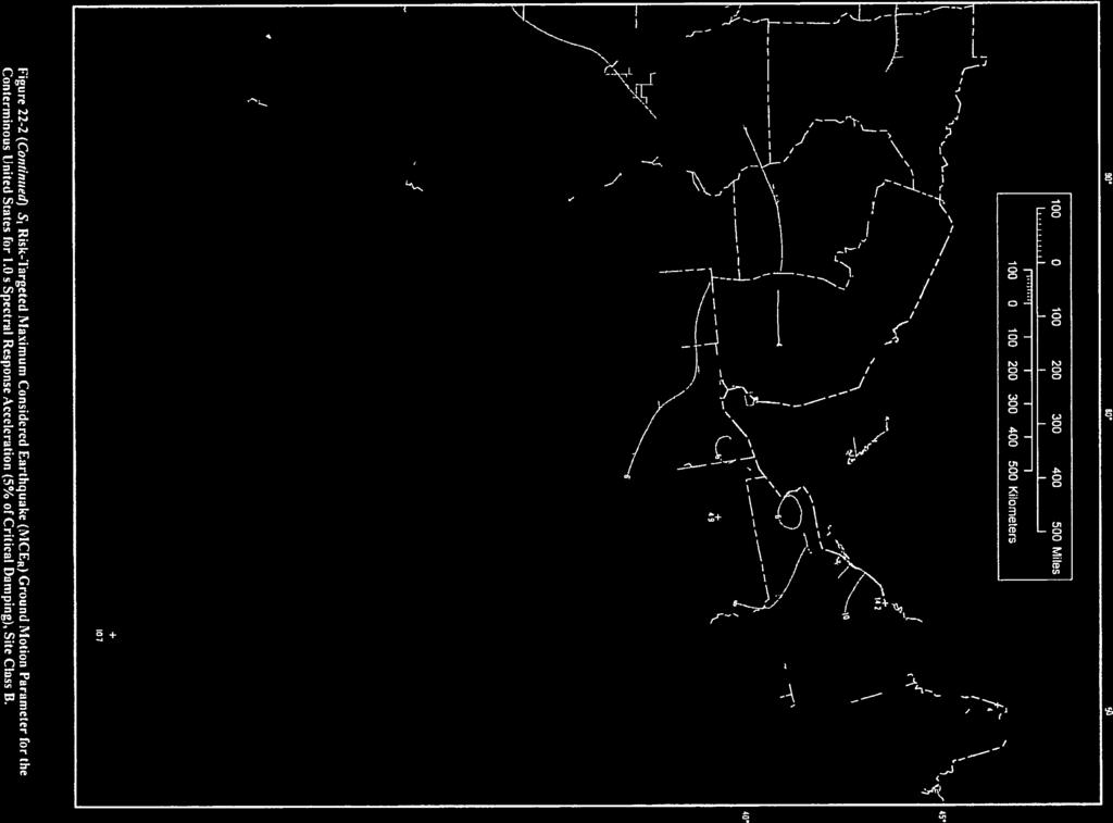
6 SEISMIC IMPACT ZONE DEMONSTRATION ROCKPORT PLANT ROCKPORT, IN 3 SEISMIC IMPACT ZONE DETERMINATION (a) Per the CCR Rules Definition, a seismic impact zone means an area having a two (2%) or greater probability that the maximum expected horizontal acceleration, expressed as a percentage of the earth s gravitational pull (g), will exceed 0.10 g in 50 years. The first step toward achieving compliance with this requirement is to identify whether the impoundment site lies within a seismic impact zone as defined above. The determination of whether Rockport Plant area falls in a seismic impact zone and the level of the seismic acceleration is based on two approaches, the USGS web site as well as a site specific seismic analysis conducted for the plant area. 3.1 USGS MAP/WEB SITE DETERMINATION The U.S. Geological Survey (USGS) National Seismic Hazard Mapping Program (NSHMP) Interactive Deaggregation website was used to provide the design ground acceleration relating to the design seismic event. For a 2,475 year return period (2% exceedance probability in 50 years), the website output indicates a PGA of g for the hard rock site (Based on URS Report recommendations, APPENDIX A). The corresponding earthquake magnitude (M) was SITE SPECIFIC SEISMIC ANALYSIS URS Company (URS), Currently AECOM, performed a site specific seismic hazard analysis for the Rockport power plant site in Indiana. The objective of the study was to compute the design earthquake response spectrum for the site per the requirements in Chapter 21 of the ASCE 7 05 standard, which is incorporated by reference in the 2006 International Building Code (IBC). The study also meets the requirements of the Indiana State Building Code, which amends certain sections of the IBC. The site specific PGA computed in URS study for a 2,475 year return period is 0.13 g, very comparable to the USGS mapped value. Excerpts of the URS (AECOM) study are included in APPENDIX A. Based on the results of the two approaches, the design seismic acceleration of the facility is to be taken as g. Therefore, the BAP complex falls in a seismic impact zone and the analysis of this report will attempt to demonstrate that the Structural components including liners, leachate collection and removal systems, and surface water control systems, are designed to resist the g, maximum horizontal acceleration in lithified earth material. 4 DESCRIPTION OF THE FOUNDATION AND EMBANKEMENT MATERIALS (c)(1)(v) [A description of the physical and engineering properties of the foundation and abutment materials on which the CCR unit is located.] The description of the BAP Complex embankment and foundations soils were based on the 2016 site investigation and laboratory testing conducted by AEP Civil Engineering Laboratory. 4.1 SITE INVESTIGATION AEP Civil Engineering Drilling crew conducted a soil site investigation of which two (2) soil test boring series (B 1605 and B 1606) that were drilled through the embankment and the foundation soils (See Figure 2), were selected for this demonstration. Representative but disturbed soil samples were Page 2 of 18
7 SEISMIC IMPACT ZONE DEMONSTRATION ROCKPORT PLANT ROCKPORT, IN collected in jars/bags and transferred to AEP Civil Engineering Laboratory for classification and testing. The Standard Penetration Resistances (N1 60 values) varied between a low of 2 to a high of 100 (refusal) blows per foot (bpf) with an average N1 60 values of 35 bpf. The soils within the embankment were lean clay extending below the embankment with a total depth of ft. The clay layer was underlain by fine to coarse sand deposits. Figure 4 present the soil profile interpreted from the two borings. Bedrock at the plant site is at approximate elevation of 290 ft msl and comprised of predominantly shale. Soil Samples from the borings at various depths were tested at AEP Civil Engineering Laboratory for the following tests: Moisture Content (ASTM 2216) Grain Size Analyses (ASTM D 422) Atterberg Limits (ASTM D 4318 Based on the lab soil tests results, the tested soils are non plastic silty sand with fine content ranging from 14.5 to 28.6% with minor pockets of sandy lean clay. Laboratory test reports are included in APPENDIX B. Soil classification, index properties, and shear strength values obtained from subsurface soil investigation and laboratory tests are summarized in Table 1 below. Table 1 Soil Properties Obtained in 2016 Investigation Laboratory Testing Soil Boring ID Sample Depth (ft) USCS Classification Fine Content (%) Moisture Content (%) Atterberg Limits LL PL PI MW 1605D ft POORLY GRADED SAND SP NP NP NP MW 1605I ft POORLY GRADED SAND SP NP NP NP MW 1605S ft POORLY GRADED SAND SP NP NP NP MW 1606D ft POORLY GRADED SAND SP NP NP NP MW 1606I ft POORLY GRADED SAND SP NP NP NP MW 1606S ft POORLY GRADED SAND SP NP NP NP APPENDIX B includes the boring logs for relevant boring 1605 and 1606 as well as the corresponding lab tests. 5 MODES OF FAILURE AND STABILITY DEMONSTRATION Based on (a) part of the Rules, only East and West bottom Ash Ponds are required to be covered under this demonstration. Seismic impact zones Structural components including liners, leachate collection and removal systems, and surface water control systems, are designed to resist the maximum horizontal acceleration in lithified earth material for the site. 5.1 FAULTS Based on the geological survey of the Pond Complex area, there is no fault exists in the locality under the ponds dikes. This mode of failure is considered not applicable for the bottom ash pond complex. Based on published data no active faults are known to traverse the site and no surficial evidence of faulting was observed during various field investigation conducted at the site. Figure 5 and Figure 6 Page 3 of 18
8 SEISMIC IMPACT ZONE DEMONSTRATION ROCKPORT PLANT ROCKPORT, IN present the nearest mapped fault trace considered to be active is one of a group of faults located approximately 5 miles west of the site. 5.2 LIQUEFACTION POTENTIAL Liquefaction is a condition where seismic ground motions cause excessive pore pressures in soils that result in a loss in shear strength. Liquefaction can cause slope instability and/or settlement. Liquefaction is most likely to occur for (1) loose sands/silts, (2) shallow groundwater conditions, and (3) strong ground motions. Liquefaction potential analysis was performed using LiquefyPro program developed by CivilTech Software Company. The program evaluates liquefaction potential and calculates the settlement of soil deposits due to seismic loads. LiquefyPro program is based on the most recent publications of the NCEER Workshop and SP117 Implementation. The user can choose between several different methods for liquefaction evaluation: one method for SPT and four methods for CPT data. Each method has different options that can be changed by the user. The options include Fines Correction, Hammer Type for SPT test, and Average Grain Size (D50) for CPT. The liquefaction analysis used the standard penetration (SPT) N values recoded on the logs for the existing testing boring and monitoring wells MW 1605 and The liquefaction analysis has been performed for N1 60 values recorded in the upper 100 feet although the RCRA Subtitle D (258) Seismic Design Guidance for Municipal Solid Waste Landfill Facilities (U.S.EPA, 1995) states that liquefaction is generally not likely to occur more than 50 feet below the ground surface. At the BAP Complex, groundwater is at 27 to 30 feet below the ground surface. The results of the liquefaction analysis are summarized in Table 2 and Figure 7 and Figure 8. The detail of the analysis is included in APPENDIX C. The analysis shows that liquefaction is unlikely for the embankment and the foundations soils during the assumed PGA. Table 2 Summary of Supplemental Liquefaction Potential Results Section Minimum Factor of Safety Required Minimum Factor of Safety Notes B 1605 > None B 1606 > None 5.3 SEISMIC INDUCED PERMANENT DISPLACEMENT The computer program LiquefyPro developed by developed by CivilTech Software Company was used to predict the likely magnitude of seismically induced permanent displacements. LiquefyPro performs numerical double integration of the HEA values that are in excess of the yield acceleration values. LiquefyPro divides the soil deposit into very thin layers and calculates the settlement for each layer. The calculations are divided into two parts, dry soil settlement and saturated soil settlement. The soil above the groundwater table is referred to as dry soil and soil below the groundwater table is referred to as saturated soil. The total settlement at a certain depth is the sum of the settlements of the saturated and Page 4 of 18
9 SEISMIC IMPACT ZONE DEMONSTRATION ROCKPORT PLANT ROCKPORT, IN dry soil. The total settlement is presented in the graphical report as a cumulative settlement curve versus depth. LiquefyPro gives settlement in both liquefied and non liquefied zones. The results of the permanent displacement analyses using LiquefyPro are presented graphically in Figure 7 and Figure 8. The figures indicate that the seismic induced permanent displacement are very small and range from 0 to 0.01 feet (0 to 0.12 inches). 5.4 SEISMIC SLOPE STABILITY As a part of the factor of Structural integrity criteria assessment part of the CCR Rule (CFR e), Terracon Inc. conducted seismic slope stability analysis in 2016 for the worst section of the bottom ash pond which is the outer dike. Factor of safety of 1.21 and 2.14 were calculated for worst case section shown in Figure 9 Figure 10 for the upstream slopes and downstream slopes, respectively. The figures show the geometry of the worst case section along with their material properties for the various soil layers, the projected slip failure, and the resulting factor of safety. 5.5 OVER TOPPING OF CREST The west bottom ash pond is comprised of diked embankment to the west and between its respective waste water pond and adjacent east bottom ash pond that directs storm water away from the impoundment and limits runoff to that which falls directly onto the water surface. The land area to the north is an open field area that is not graded toward the Bottom Ash Complex. The east bottom ash pond has a small 13 acre catchment area that will drain into the pond. Flow into the west bottom ash pond was modeled as the pumped influent from the plant (77 ac ft) and from the storm event (48 ac ft) and discharged through the pond complex to the Ohio River. The Bottom Ash Pond Complex has been determined to be a Low Hazard potential CCR impoundment. Based on this hazard classification, the design flood as determined by section (a)(3) to be the 100 year storm event that would incur 7.23 inches of precipitation in a 24 hour period. Terracon, 2015 conducted hydraulic and hydrogeologic study in which the site was modeled, however, using a greater storm (1,000 year: 10.3 inches of precipitation in 24 hrs) event to provide a more conservative analysis. The following table provides the maximum inflows, outflows and flood elevations for the west bottom ash pond. West Bottom Ash Pond* Storm Event 1000 yr. Peak Inflow 470 cfs Peak Outflow 35 cfs Maximum Pool Elevation 395 ft. Crest Elevation 399 ft. *Reference: Terracon 2015, Hydrologic and Hydraulic Analysis Report, Rockport Plant Bottom Ash Pond Complex, Rockport Indiana, Terracon Project No. N It can be concluded from the above results that the Bottom Ash Pond Complex has adequate hydrologic and hydraulic capacity to collect and control the peak discharge resulting from the 1000 year inflow design flood and therefore the overtopping of the crest is not anticipated. Page 5 of 18
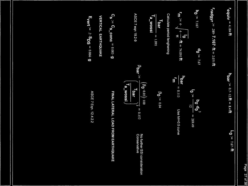
10 SEISMIC IMPACT ZONE DEMONSTRATION ROCKPORT PLANT ROCKPORT, IN 5.6 LINER The Ponds are CCR surface impoundments that are not equipped with a liner; therefore, this demonstration is not applicable. 5.7 LEACHATE COLLECTION AND REMOVAL SYSTEMS The Ponds are CCR surface impoundments that are not equipped with a leachate collection and removal systems; therefore, this demonstration is not applicable. 5.8 SURFACE WATER CONTROL SYSTEMS The surface water control structures were constructed in the late 70s and early 80s for the 2 unit operating plant with a total capacity of approximately 2,600 MW. The structures reviewed in this demonstration are all surface water control units facilitating water flow into and from the bottom ash ponds to the clear water ponds. The components included in the demonstration can be classified into two groups: Group 1: components subjected to lateral loading due to the quakes used for transferring water from bottom ash ponds to waste water ponds including units used to dewater the BA ponds. The components are: 1. Energy Dissipater structure (EDS 2 nos.) approximately 8 plant pipes of 8 10 inch diameter pipes discharging into this structure and then transported into the BA pond through the Energy Dissipater troughs/pond Discharge Inlet Chutes. EDSs are of concrete with steel dissipation flaps. 2. Energy Dissipater troughs/pond Discharge Inlet Chutes (EDT) These are concrete structures partially open at the top and partially covered by yellow steel boxes called Discharge Chute Covers. 3. Skimmers (SKM) Timber structures surrounding the waste water discharge chute. 4. Waste water Discharge shaft (WWDS) a steel and concrete prismoidal structure for routing waste water into the waste water discharge pipe. Group 2: Waste Water Discharge Pipe (WWDP) Two buried 48 inch (one fiberglass and the other HDPE) pipes that transfer water under the dikes. Because they are buried they are affected by seismic waves and ground displacements. Details of the analysis and are included in APPENDIX D. Appendix D contains the relevant calculations for the structures with the assumption that the dike stability against any seismic failure including liquefaction can be concluded. With this calculation results, the dike has been found stable. Therefore, the assumption is no more a restraint to use this calculation. The conclusion of the presented analysis indicated that 1. Based on a typical configuration, the seismic analyses of the structures are judged to meet local seismic requirements. 6 SUMMARY AND CONCLUSIONS The Bottom Ash Pond Complex is a surface impoundment for storing CCR. The Bottom Ash Ponds within the complex are used for primary settling and storage of bottom ash. The Bottom Ash Pond Complex is located in an area having a two (2%) or greater probability that the maximum expected horizontal acceleration, expressed as a percentage of the earth s gravitational pull (g) of g in 50 years, which is in excess of the 0.10 g maximum horizontal acceleration in lithified earth material. Therefore, a demonstration that all structural components including liners, leachate collection and removal systems, and surface water control systems, are designed to resist the maximum horizontal acceleration in Page 6 of 18
11 SEISMIC IMPACT ZONE DEMONSTRATION ROCKPORT PLANT ROCKPORT, IN lithified earth material for the site was conducted per the requirements of CFR Seismic Impact Zones. Based on the analysis conducted in this report, all structural components including liners, leachate collection and removal systems, and surface water control systems, are designed to resist the maximum horizontal acceleration and the Bottom Ash Pond Complex meets the requirements of Seismic Impact Zones. 7 REFERENCES USEPA, CFR Parts 257 and 261, Hazardous and Solid Waste Management System; Disposal of Coal Combustion Residuals from Electric Utilities; Final Rule. April 17, pp. Site Specific Seismic hazard analysis for AEP power plant site, Rockport, Indiana URS corporation (currently AECOM) (2012). Terracon 2015, Hydrologic and Hydraulic Analysis Report, Rockport Plant Bottom Ash Pond Complex, Rockport Indiana, Terracon Project No. N Terracon, Geotechnical Engineering Report, AEP Rockport Bottom Ash Complex Professional Engineering Certification. Page 7 of 18
12 SEISMIC IMPACT ZONE DEMONSTRATION ROCKPORT PLANT ROCKPORT, IN Figures Page 8 of18

13 SEISMIC IMPACT ZONE DEMONSTRATION ROCKPORT PLANT ROCKPORT, IN Figure 1 Rockport Power Station s Bottom Ash pond Complex Location Map Page 9 of18
 Page 10")
14 SEISMIC IMPACT ZONE DEMONSTRATION ROCKPORT PLANT ROCKPORT, IN Figure 2 Rockport Power Station s BAP Plan View (Includes Borings location) Page 10 of18
15 SEISMIC IMPACT ZONE DEMONSTRATION ROCKPORT PLANT ROCKPORT, IN Figure 3 Maximum expected Earthquake Magnitude and horizontal acceleration based on U.S. Geological Survey Web Site Page 11 of18
16 SEISMIC IMPACT ZONE DEMONSTRATION ROCKPORT PLANT ROCKPORT, IN Figure 4 Soil Profile Interpreted from the Two Borings. Page 12 of18

17 SEISMIC IMPACT ZONE DEMONSTRATION ROCKPORT PLANT ROCKPORT, IN Figure 5 Regional Faults Location Map Page 13 of18
18 SEISMIC IMPACT ZONE DEMONSTRATION ROCKPORT PLANT ROCKPORT, IN Figure 6 Local Faults Location Map Page 14 of18
19 SEISMIC IMPACT ZONE DEMONSTRATION ROCKPORT PLANT ROCKPORT, IN SEISMIC IMPACT ZONES DEMONSTRATION Bottom Ash Complex -Rockport Plant Hole No.=1605 Water Depth=30 ft Surface Elev.=399 Magnitude=6.46 Acceleration= g (ft) 0 Shear Stress Ratio Factor of Safety Settlement 0 (in.) 1 Soil Description Lean Clay Silt Lean Clay 20 Poorly Graded Sand 40 Well Graded Sand Poorly Graded Sand 60 Well Graded Sand 80 Poorly Graded Sand Silt LiquefyPro CivilTech Software USA fs1=1 CRR CSR fs1 Shaded Zone has Liquefaction Potential 140 S = 0.07 in. Saturated Unsaturat. Well Graded Sand Poorly Graded Sand Well Graded Sand Poorly Graded Sand Silt Plate A-1 American Electric Power Service Corporation Figure 7 Liquefaction Analysis Results for B 1605Location Page 15 of18
20 SEISMIC IMPACT ZONE DEMONSTRATION ROCKPORT PLANT ROCKPORT, IN SEISMIC IMPACT ZONES DEMONSTRATION Bottom Ash Complex -Rockport Plant Hole No.=1606 Water Depth=27 ft Surface Elev.=397.8 Magnitude=6.46 Acceleration= g (ft) 0 Shear Stress Ratio Factor of Safety Settlement 0 (in.) 1 Soil Description Lean Clay 20 Poorly Graded Sand 40 Lean Clay 60 Poorly Graded Sand LiquefyPro CivilTech Software USA fs1=1 CRR CSR fs1 Shaded Zone has Liquefaction Potential S = 0.12 in. Saturated Unsaturat. Silt Plate A-1 American Electric Power Service Corporation Figure 8 Liquefaction Analysis Results for B 1606Location Page 16 of18
 Page 17")
21 SEISMIC IMPACT ZONE DEMONSTRATION ROCKPORT PLANT ROCKPORT, IN Figure 9 Results of Seismic Stability Analysis (Upstream) Page 17 of18
 Page")
22 SEISMIC IMPACT ZONE DEMONSTRATION ROCKPORT PLANT ROCKPORT, IN Figure 10 Results of Seismic Stability Analysis (Downstream) Page 18 of18
23 SEISMIC IMPACT ZONE DEMONSTRATION ROCKPORT PLANT ROCKPORT, IN APPENDICIES
24 SEISMIC IMPACT ZONE DEMONSTRATION ROCKPORT PLANT ROCKPORT, IN APPENDIx A : Excerpts from the SITE SPECIFIC SEISMIC HAZARD ANALYSIS
25 SEISMIC IMPACT ZONE DEMONSTRATION ROCKPORT PLANT ROCKPORT, IN


26 SEISMIC IMPACT ZONE DEMONSTRATION ROCKPORT PLANT ROCKPORT, IN
27 SEISMIC IMPACT ZONE DEMONSTRATION ROCKPORT PLANT ROCKPORT, IN APPENDIx B :Soil boring logs along with soil classification sheets
28 JOB NUMBER COMPANY AMERICAN ELECTRIC POWER SERVICE CORPORATION AEP CIVIL ENGINEERING LABORATORY LOG OF BORING INDIANA MICHIGAN POWER COMPANY BORING NO. MW-1605D DATE 4/27/16 SHEET 1 OF 6 ROCKPORT PLANT BORING START BORING FINISH 2/3/16 N 151,478.9 E 513,537.1 PIEZOMETER TYPE WELL TYPE OW State Plane using SYSTEM NAD27/29 HGT. RISER ABOVE GROUND 3.36 DIA 2.0 DEPTH TO TOP OF WELL SCREEN 114.6BOTTOM WELL DEVELOPMENT YES BACKFILL FIELD PARTY ZLR / REB RIG D-50 PROJECT 2/3/16 COORDINATES GROUND ELEVATION Water Level, ft TIME DATE SAMPLE NUMBER 1 2 SAMPLE SAMPLE DEPTH IN FEET FROM 0.0 TO 3.0 STANDARD PENETRATION RESISTANCE BLOWS / 6" TOTAL LENGTH RECOVERY RQD % DEPTH IN FEET GRAPHIC LOG U S C S CL Gravel = 6 inches SOIL / ROCK IDENTIFICATION Silty clay, moderate yellowish brown 10R 5/4 and med l. grey N6 mottled, moist, v. ' 3' v. stiff WELL DRILLER'S NOTES ML Clayey silt, medium grey N5, moist, med. dense, w/mod. yellowish brown 10R 5/4 silty clay mottled CL Silty clay, mod. yellowish brown 10R 5/4, moist, stiff, w/med. grey N5 clayey silt mottled CH Fat to lean clay, med. l. grey N6, moist, firm AEP RK BAP CCR COMPLIANCE.GPJ AEP.GDT 4/27/ TYPE OF CASING USED NQ-2 ROCK CORE 6" x 3.25 HSA 9" x 6.25 HSA HW CASING ADVANCER NW CASING SW CASING AIR HAMMER " 3" 6" 8" 15 CL ML PIEZOMETER TYPE: Silty clay, mod. reddish brown 10R 4/6 w/med. l. grey N6 fat clay heavily mottled, moist, 15' 15.5' l" shale fragment, 18' very 20' trace to some pale yellowish brown 10YR 6/2 silt RECORDER Continued Next Page PT = OPEN TUBE POROUS TIP, = OPEN TUBE SLOTTED SCREEN, G = GEONOR, P = PNEUMATIC WELL TYPE: OW = OPEN TUBE SLOTTED SCREEN, GM = GEOMON AMEC FOSTER WHEELER
29 JOB NUMBER COMPANY AMERICAN ELECTRIC POWER SERVICE CORPORATION AEP CIVIL ENGINEERING LABORATORY LOG OF BORING INDIANA MICHIGAN POWER COMPANY MW-1605D DATE ROCKPORT PLANT BORING START PROJECT 2/3/16 BORING NO. 4/27/16 SHEET BORING FINISH 2 2/3/16 OF 6 SAMPLE NUMBER SAMPLE SAMPLE DEPTH IN FEET FROM TO STANDARD PENETRATION RESISTANCE BLOWS / 6" TOTAL LENGTH RECOVERY RQD % DEPTH IN FEET GRAPHIC LOG U S C S SOIL / ROCK IDENTIFICATION WELL DRILLER'S NOTES ML Clayey silt, pale yellowish brown 10YR 6/2, moist, med. dense, w/silty clay (prev. material), trace sand SP ML Poorly graded sand, v. fine to fine grained, l. brown 5YR 5/6, moist, 23.2' 2" clayey silt seam (prev. material) Clayey silt, pale yellowish brown 10YR 6/2, moist to wet, v. 25' 2" l. brown sand seam (prev. 26' 2" l. brown sand 26.4' 15" l. brown sand 26.8' l" l. brown sand 27' 28' 2" l. brown sand seam SP Poorly graded sand, fine grained, l. brown 5YR 5/6, moist, med. 30' d. yellowish orange 10YR 31' 3" clayey silt seam (prev. 32.3' trace fine gravel and black 32.5' no fine gravel or 33' moist, 34.1' 2" clayey silt seam (prev. 34.5' moist to wet, water in 34.9' 2.5' clayey silt seam (prev. material) AEP RK BAP CCR COMPLIANCE.GPJ AEP.GDT 4/27/ SW SW SP SW SP SW SP Well graded sand, fine grained, l. brown 5YR 5/6, moist to wet, med. dense, w/fine gravel Well graded sand, coarse grained, grayish black N2, moist to wet, med. dense, trace fine gravel Poorly graded sand, v. fine grained, l. brown 5YR 5/6, moist to wet, med. dense Well graded sand, fine to med. grained, moderate yellowish brown 10YR 5/4, moist to wet, 40.5' med. 41' " shale seam w/clay Poorly graded sand, v. fine to fine grained, mod. yellowish brown 10YR 5/4, moist to wet, med. dense Well graded sand, med. grained, mod. reddish brown 10R 4/6, moist to wet, med. 44' med. to coarse grained Poorly graded sand, fine grained, mod. yellowish Continued Next Page
30 JOB NUMBER COMPANY AMERICAN ELECTRIC POWER SERVICE CORPORATION AEP CIVIL ENGINEERING LABORATORY LOG OF BORING INDIANA MICHIGAN POWER COMPANY MW-1605D DATE ROCKPORT PLANT BORING START PROJECT 2/3/16 BORING NO. 4/27/16 SHEET BORING FINISH 3 2/3/16 OF 6 SAMPLE NUMBER SAMPLE SAMPLE DEPTH IN FEET FROM TO STANDARD PENETRATION RESISTANCE BLOWS / 6" TOTAL LENGTH RECOVERY 1.33 RQD % DEPTH IN FEET 50 GRAPHIC LOG U S C S SW SP SOIL / ROCK IDENTIFICATION brown 10YR 5/4, moist to wet, mod. dense, some fine gravel Well graded sand, med. to coarse grained, mod. reddish brown 10R 4/6, moist to wet, med. dense, trace fine gravel Poorly graded sand, fine grained, mod. yellowish brown 10YR 5/4, moist to wet, med. dense, trace fine 48' w/fine gravel, trace coarse 49.5' no coarse gravel WELL DRILLER'S NOTES SW SP Well graded sand, med. to coarse grained, mod. reddish brown 10R 4/6, moist to wet, mod. dense, trace fine gravel Poorly graded sand, fine grained, mod. yellowish brown 10YR 5/4, moist to wet, mod. dense, trace fine 54' no fine gravel, 57' wet, mod. 60' 63' mod. dense SW Well graded sand, med. to coarse grained, mod. yellowish brown 10YR 5/4, moist to wet, mod. dense, trace black silt AEP RK BAP CCR COMPLIANCE.GPJ AEP.GDT 4/27/ SP Poorly graded sand, fine grained, mod. yellowish brown 10YR 5/4, moist to wet, mod. 68.5' trace fine gravel, trace coal 70' no fine gravel, no coal 70.9' trace fine 71.6' no fine gravel, wet Continued Next Page
31 JOB NUMBER COMPANY AMERICAN ELECTRIC POWER SERVICE CORPORATION AEP CIVIL ENGINEERING LABORATORY LOG OF BORING INDIANA MICHIGAN POWER COMPANY MW-1605D DATE ROCKPORT PLANT BORING START PROJECT 2/3/16 BORING NO. 4/27/16 SHEET BORING FINISH 4 2/3/16 OF 6 SAMPLE NUMBER SAMPLE SAMPLE DEPTH IN FEET FROM TO STANDARD PENETRATION RESISTANCE BLOWS / 6" TOTAL LENGTH RECOVERY RQD % DEPTH IN FEET GRAPHIC LOG U S C S SW SOIL / ROCK IDENTIFICATION Well graded sand, fine grained d. yellowish brown 10YR 4/2, moist to wet, mod. dense, trace fine 73.5' w/fine gravel, trace coarse gravel WELL DRILLER'S NOTES SW SP Well graded sand, coarse grained, brownish grey 5YR 4/1, moist to wet, mod. dense, w/fine gravel, trace coarse gravel Poorly graded sand, fine grained, pale yellowish brown 10YR 6/2, wet, dense, trace fine 78' mod. 81' v. fine to fine 82.5' no fine 84' 85' 2" shale 85.2' v. fine 85.5' 3.5" shale 87' fine grained, d. yellowish brown 10YR 88.5' v. fine grained, mod. dense ML Clayey silt, med. l. grey N6, moist to wet, mod. dense AEP RK BAP CCR COMPLIANCE.GPJ AEP.GDT 4/27/ SP ML SW ML SW ML SW Poorly graded sand, fine grained, d. yellowish brown 10YR 4/2, moist, dense Clayey silt, med. l. grey N6, moist to wet, dense Well graded sand, coarse grained, med. grey N5, w/fine gravel, some coarse gravel Clayey silt, med. l. grey N6, moist to wet, dense Well graded sand, fine grained, med. grey N5, moist to wet, dense, w/fine gravel Clayey silt, med. l. grey N6, moist to wet, dense Well graded sand, coarse grained, med. grey N5, moist to wet, dense, w/fine 98.7' coal fragments Continued Next Page
32 JOB NUMBER COMPANY AMERICAN ELECTRIC POWER SERVICE CORPORATION AEP CIVIL ENGINEERING LABORATORY LOG OF BORING INDIANA MICHIGAN POWER COMPANY MW-1605D DATE ROCKPORT PLANT BORING START PROJECT 2/3/16 BORING NO. 4/27/16 SHEET BORING FINISH 5 2/3/16 OF 6 SAMPLE NUMBER SAMPLE SAMPLE DEPTH IN FEET FROM TO STANDARD PENETRATION RESISTANCE BLOWS / 6" TOTAL LENGTH RECOVERY RQD % DEPTH IN FEET GRAPHIC LOG U S C S SOIL / ROCK IDENTIFICATION WELL DRILLER'S NOTES SP Poorly graded sand, v. fine to fine grained, pale yellowish brown 10YR 6/2, moist to wet, dense, w/fine 100.5' no fine gravel, mod. 102' v. fine, 105' mod. 106' trace coal 106.3' no coal 109.5' 111' v. moist to 112.5' moist to wet, 113' trace fine gravel, trace coarse 113.5' no fine gravel, no coarse gravel SW Well graded sand, med. to coarse grained, med. grey N5, moist to wet, dense, w/fine gravel, some coarse 115.5' coarse grained, mod. dense, trace coarse 118.5' v. dense AEP RK BAP CCR COMPLIANCE.GPJ AEP.GDT 4/27/ SP Poorly graded sand, v. fine grained, med. l. grey N6, moist to wet, v. 120' med. dense, sl. 122' fine grained, w/fine gravel, 124.5' trace coarse gravel Continued Next Page
33 AMERICAN ELECTRIC POWER SERVICE CORPORATION AEP CIVIL ENGINEERING LABORATORY LOG OF BORING JOB NUMBER COMPANY INDIANA MICHIGAN POWER COMPANY BORING NO. MW-1605D DATE 4/27/16 SHEET 6 OF 6 PROJECT ROCKPORT PLANT BORING START 2/3/16 BORING FINISH 2/3/16 SAMPLE NUMBER SAMPLE SAMPLE DEPTH IN FEET FROM TO STANDARD PENETRATION RESISTANCE BLOWS / 6" TOTAL LENGTH RECOVERY RQD % DEPTH IN FEET GRAPHIC LOG U S C S SOIL / ROCK IDENTIFICATION WELL DRILLER'S NOTES /5 125 ML Clayey silt, l. grey N7, moist, hard, non-durable 126' flaky, dry to moist Spoon 127.4' Auger (shale) /2.66 AEP RK BAP CCR COMPLIANCE.GPJ AEP.GDT 4/27/16
34 JOB NUMBER COMPANY AMERICAN ELECTRIC POWER SERVICE CORPORATION AEP CIVIL ENGINEERING LABORATORY LOG OF BORING INDIANA MICHIGAN POWER COMPANY BORING NO. MW-1606D DATE 4/27/16 SHEET 1 OF 5 ROCKPORT PLANT BORING START BORING FINISH 2/12/16 N 151,502.1 E 512,88 PIEZOMETER TYPE WELL TYPE OW State Plane using SYSTEM NAD27/29 HGT. RISER ABOVE GROUND 2.91 DIA 2.0 DEPTH TO TOP OF WELL SCREEN 100.2BOTTOM WELL DEVELOPMENT YES BACKFILL FIELD PARTY ZLR / REB RIG D-120 PROJECT 2/12/16 COORDINATES GROUND ELEVATION Water Level, ft TIME DATE SAMPLE NUMBER 1 2 SAMPLE SAMPLE DEPTH IN FEET FROM 0.0 TO 3.0 STANDARD PENETRATION RESISTANCE BLOWS / 6" TOTAL LENGTH RECOVERY RQD % DEPTH IN FEET GRAPHIC LOG U S C S CL SOIL / ROCK IDENTIFICATION Crushed stone gravel (limestone) Lean clay, moderate yellowish brown 10YR 5/4, moist, trace fine grained sand, ' as above, trace coarse grain sand and black decomposed organic 3' trace fine gravel WELL DRILLER'S NOTES CL CL Lean clay, pale yellow brown 10YR 6/2, moist, some light brown oxide 6.0' yellow brown and brown 10YR 7.5' pale yellow brown 10YR 6/2, trace fine roots, trace fine grained sand Lean clay w/sand, dark yellow brown 10YR 4/2, moist, little fine grained sand CL Lean clay, light bluish gray 5B 7/1, moist, some brown oxide staining, trace coarse grained 12.5' as above, becomes moderate brown in color 5YR 13.5' moderate yellow brown 10YR 5/4 and pale yellow brown 10YR 6/2) 13.5' - 15' trace fine grained sand, trace fine 19.5' mostly 10YR 6/2 in color AEP RK BAP CCR COMPLIANCE.GPJ AEP.GDT 4/27/ TYPE OF CASING USED NQ-2 ROCK CORE 6" x 3.25 HSA 9" x 6.25 HSA HW CASING ADVANCER NW CASING SW CASING AIR HAMMER 4" 3" 6" 8" PIEZOMETER TYPE: RECORDER Continued Next Page PT = OPEN TUBE POROUS TIP, = OPEN TUBE SLOTTED SCREEN, G = GEONOR, P = PNEUMATIC WELL TYPE: OW = OPEN TUBE SLOTTED SCREEN, GM = GEOMON AMEC FOSTER WHEELER
35 JOB NUMBER COMPANY AMERICAN ELECTRIC POWER SERVICE CORPORATION AEP CIVIL ENGINEERING LABORATORY LOG OF BORING INDIANA MICHIGAN POWER COMPANY MW-1606D DATE ROCKPORT PLANT BORING START BORING NO. 4/27/16 SHEET PROJECT 2/12/16 BORING FINISH 2 2/12/16 OF 5 SAMPLE NUMBER SAMPLE SAMPLE DEPTH IN FEET FROM TO STANDARD PENETRATION RESISTANCE BLOWS / 6" TOTAL LENGTH RECOVERY RQD % DEPTH IN FEET GRAPHIC LOG U S C S SOIL / ROCK IDENTIFICATION WELL DRILLER'S NOTES CL ML Silty clay, pale yellow brown 10YR 6/2, moist, trace to little fine grained sand SP SM Poorly graded sand w/silt, pale yellow brown 10YR 6/2, moist, fine to medium grained 24.9' 3" silt layer CL Lean clay, moderate yellowish brown 10YR 5/4, moist, few sandy layers <1" 28.3' SP-SM layer (~3" thick) SP SM Poorly graded sand w/silt, dark yellowish orange 10YR 6/6, wet, fine to medium grained sand, little coarse grained 3' trace fine 34.5' trace fine gravel AEP RK BAP CCR COMPLIANCE.GPJ AEP.GDT 4/27/ SP SP SM SC SP Poorly graded sand, dark yellowish orange 10YR 6/6, wet, fine to medium grained sand, trace to little coarse grained 37.5' trace gravel Poorly graded sand w/silt, dark yellowish orange 10YR 6/6, wet, fine to medium grained sand, trace coarse grained sand Clayey sand, moderate brown 5YR 3/4, wet, fine to medium grained sand Poorly graded sand, dark yellowish orange 10YR 6/6, wet, fine to medium grained sand, trace coarse grained sand & fine 42.0' ' increase in coarse grained 45.2' ' color change to moderate brown 5YR 46.5' increase in coarse grained sand, trace wood fragments (tree 48' color change to pale yellowish brown 10YR Continued Next Page
36 JOB NUMBER COMPANY AMERICAN ELECTRIC POWER SERVICE CORPORATION AEP CIVIL ENGINEERING LABORATORY LOG OF BORING INDIANA MICHIGAN POWER COMPANY MW-1606D DATE ROCKPORT PLANT BORING START BORING NO. 4/27/16 SHEET PROJECT 2/12/16 BORING FINISH 3 2/12/16 OF 5 SAMPLE NUMBER 32 SAMPLE SAMPLE DEPTH IN FEET FROM 46.5 TO 48.0 STANDARD PENETRATION RESISTANCE BLOWS / 6" TOTAL LENGTH RECOVERY 1.1 RQD % DEPTH IN FEET GRAPHIC LOG U S C S SOIL / ROCK IDENTIFICATION 6/2, few black decomposed organic layers WELL DRILLER'S NOTES SW SM Well graded sand w/silt & gravel, wet, pale yellowish brown 10YR 6/2, fine to coarse grained sand, little to some fine gravel, trace coarse gravel SP SM Poorly graded sand w/silt, moderate yellowish brown 10YR 5/4, wet, fine to medium grained sand, trace coarse grained sand, few layers of decomposed organics (from 51' - 54' trace coarse gravel, fines between 55.5' trace fine gravel SW Well graded sand, med. to coarse grained, dark yellowish brown 10YR 4/2), wet, med. dense, trace fine 59' trace coarse gravel SP Poorly graded sand, fine grained, dusky yellowish brown 10YR 2/2, wet, med. dense, w/fine 60.5' 2" shale 6' dark yellowish brown 10YR 4/2, 61.8' 2" shale 62' some lean clay, pale yellowish brown (prev. 62.5' no clay, trace fine 63' no fine 64.5' med. 65.8' 15" coarse sand seam (prev. 66' 67.2' 3" shale seam, med. l. grey 67.7' med. grained AEP RK BAP CCR COMPLIANCE.GPJ AEP.GDT 4/27/ SP Poorly graded sand, fine gravel, pale yellowish brown 10YR 6.2, wet, 69' moist to v. 72' med. dense, fine 75' dense, d. yellowish brown 10YR 76.5' med. dense, trace black " shale plug (responsible for increase in N value (same 81.3' " shale plug, dense Continued Next Page
37 JOB NUMBER COMPANY AMERICAN ELECTRIC POWER SERVICE CORPORATION AEP CIVIL ENGINEERING LABORATORY LOG OF BORING INDIANA MICHIGAN POWER COMPANY MW-1606D DATE ROCKPORT PLANT BORING START BORING NO. 4/27/16 SHEET PROJECT 2/12/16 BORING FINISH 4 2/12/16 OF 5 SAMPLE NUMBER 49 SAMPLE SAMPLE DEPTH IN FEET FROM 72.0 TO 73.5 STANDARD PENETRATION RESISTANCE BLOWS / 6" TOTAL LENGTH RECOVERY 1.3 RQD % DEPTH IN FEET GRAPHIC LOG U S C S SOIL / ROCK 8' no recovery, potential cobble blocking during sampling WELL DRILLER'S NOTES CH SW Fat clay, med. l. grey N6, moist, firm Well graded sand, med. grained, dark yellowish brown 10YR 4/2, wet, dense, w/fine 83' coal fragment (2" diam., 1" 83.6' coal fragment (2" diam, 1" thick) SP Poorly graded sand, fine grained, pale yellowish brown 10YR 6/2, wet, 88.5' trace fine 9' with fine gravel AEP RK BAP CCR COMPLIANCE.GPJ AEP.GDT 4/27/ SW SP SW SP SP Well graded sand, med. to coarse grained, dark yellowish brown 10YR 4/2, wet, med. dense, w/fine gravel Poorly graded sand, coarse grained, greyish red 5R 4/2, wet, med. dense, trace fine gravel Well graded sand, med. to coarse grained, dark yellowish brown 10YR 4/2, wet, med. dense, w/fine gravel Continued Next Page
38 AMERICAN ELECTRIC POWER SERVICE CORPORATION AEP CIVIL ENGINEERING LABORATORY LOG OF BORING JOB NUMBER COMPANY INDIANA MICHIGAN POWER COMPANY BORING NO. MW-1606D DATE 4/27/16 SHEET 5 OF 5 PROJECT ROCKPORT PLANT BORING START 2/12/16 BORING FINISH 2/12/16 SAMPLE NUMBER 67 SAMPLE SAMPLE DEPTH IN FEET FROM 99.0 TO STANDARD PENETRATION RESISTANCE BLOWS / 6" TOTAL LENGTH RECOVERY RQD % DEPTH IN FEET 100 GRAPHIC LOG U S C S SOIL / ROCK IDENTIFICATION Poorly graded sand, coarse grained, greyish red 5R 4/2, wet, med. dense to loose, trace fine gravel Poorly graded sand, fine grained, pale yellowish brown 10YR 6/2, wet, 97.5' med. dense, fine grained WELL DRILLER'S NOTES SP Poorly graded sand, fine to fine grained, dusky red 5R 3/4, wet, med. 102' loose, fine grained, 103.5' med. 105' fine 106.5' 108' med. dense, trace fine 109' no fine siltstone fragments to 2.5", moderate brown 5YR 4/4, shiny, angular /3 50/4 ML Silt, l. grey N7, moist, med. dense, non-durable 111' clayey silt, hard Spoon 111.7' Auger ' AEP RK BAP CCR COMPLIANCE.GPJ AEP.GDT 4/27/16
39 100 U.S. SIEVE OPENING IN INCHES /4 1/2 3/ U.S. SIEVE NUMBERS HYDROMETER P E R C E N T F I N E R 50 B Y W E I G H T GRAIN SIZE IN MILLIMETERS COBBLES GRAVEL coarse fine coarse SAND medium fine SILT OR CLAY Specimen Identification Classification MC% LL PL PI Sp.Gr. MW-1605D ft 14.5 Specimen Identification MW-1605D ft -78,79,80,81,82,83 (Composite N 151,478.9 Sample) E 513,537.1 ELEVATION D100 D60 D30 D10 %Gravel %Sand %Fines %< PROJECT ROCKPORT PLANT - JOB NO DATE 3/22/16 GRADATION CURVES American Electric Power Service Corp.
40 100 U.S. SIEVE OPENING IN INCHES /4 1/2 3/ U.S. SIEVE NUMBERS HYDROMETER P E R C E N T F I N E R 50 B Y W E I G H T GRAIN SIZE IN MILLIMETERS GRAVEL SAND COBBLES coarse fine coarse medium Specimen Identification Classification MW-1605I ft Specimen Identification MW-1605I ft fine SILT OR CLAY MC% LL PL PI Sp.Gr POORLY GRADED SAND SP -48,49,50,51,52 (Composite Sample) N 151,478.9 E 513,532.6 ELEVATION D100 D60 D30 D10 %Gravel %Sand %Fines %< PROJECT ROCKPORT PLANT - JOB NO DATE 3/22/16 GRADATION CURVES American Electric Power Service Corp.
41 100 U.S. SIEVE OPENING IN INCHES /4 1/2 3/ U.S. SIEVE NUMBERS HYDROMETER P E R C E N T F I N E R 50 B Y W E I G H T GRAIN SIZE IN MILLIMETERS GRAVEL SAND COBBLES coarse fine coarse medium Specimen Identification Classification MW-1605S ft Specimen Identification MW-1605S ft fine SILT OR CLAY MC% LL PL PI Sp.Gr POORLY GRADED SAND SP -27,28,29,30,31 (Composite Sample) N 151,478.8 E 513,528.4 ELEVATION D100 D60 D30 D10 %Gravel %Sand %Fines %< PROJECT ROCKPORT PLANT - JOB NO DATE 3/22/16 GRADATION CURVES American Electric Power Service Corp.
42 100 U.S. SIEVE OPENING IN INCHES /4 1/2 3/ U.S. SIEVE NUMBERS HYDROMETER P E R C E N T F I N E R 50 B Y W E I G H T GRAIN SIZE IN MILLIMETERS COBBLES GRAVEL coarse fine coarse SAND medium fine SILT OR CLAY Specimen Identification Classification MC% LL PL PI Sp.Gr. MW-1606D ft 28.6 Specimen Identification MW-1606D ft -68,69,70,71,72,73 (Composite N 151,502.1 Sample) E 512,88 ELEVATION D100 D60 D30 D10 %Gravel %Sand %Fines %< PROJECT ROCKPORT PLANT - JOB NO DATE 3/22/16 GRADATION CURVES American Electric Power Service Corp.
43 100 U.S. SIEVE OPENING IN INCHES /4 1/2 3/ U.S. SIEVE NUMBERS HYDROMETER P E R C E N T F I N E R 50 B Y W E I G H T GRAIN SIZE IN MILLIMETERS COBBLES GRAVEL coarse fine coarse SAND medium fine SILT OR CLAY Specimen Identification Classification MC% LL PL PI Sp.Gr. MW-1606I ft 18.9 Specimen Identification MW-1606I ft -45,46,47,48,49,50 (Composite N 151,500.4 Sample) E 512,885.5 ELEVATION D100 D60 D30 D10 %Gravel %Sand %Fines %< PROJECT ROCKPORT PLANT - JOB NO DATE 3/22/16 GRADATION CURVES American Electric Power Service Corp.
44 100 U.S. SIEVE OPENING IN INCHES /4 1/2 3/ U.S. SIEVE NUMBERS HYDROMETER P E R C E N T F I N E R 50 B Y W E I G H T GRAIN SIZE IN MILLIMETERS GRAVEL SAND COBBLES coarse fine coarse medium Specimen Identification Classification MW-1606S ft Specimen Identification MW-1606S ft fine SILT OR CLAY MC% LL PL PI Sp.Gr POORLY GRADED SAND SP -25,26,27,28,29 (Composite Sample) N 151,498.9 E 512,889.4 ELEVATION D100 D60 D30 D10 %Gravel %Sand %Fines %< PROJECT ROCKPORT PLANT - JOB NO DATE 3/22/16 GRADATION CURVES American Electric Power Service Corp.
45 SEISMIC IMPACT ZONE DEMONSTRATION ROCKPORT PLANT ROCKPORT, IN APPENDIx C :LiquefyPro Analysis Input and Output
46 SEISMIC IMPACT ZONES DEMONSTRATION Bottom Ash Complex -Rockport Plant Hole No.=1605 Water Depth=30 ft Surface Elev.=399 Magnitude=6.46 Acceleration= g N-Value Unit Weight -pcf Fines % Soil Description (ft) Lean Clay Silt Lean Clay 20 Poorly Graded Sand 40 Well Graded Sand Poorly Graded Sand 60 Well Graded Sand 80 Poorly Graded Sand Silt LiquefyPro CivilTech Software USA SPT or BPT test 140 Well Graded Sand Poorly Graded Sand Well Graded Sand Poorly Graded Sand Silt Plate A-1 American Electric Power Service Corporation
47 SEISMIC IMPACT ZONES DEMONSTRATION Bottom Ash Complex -Rockport Plant Hole No.=1605 Water Depth=30 ft Surface Elev.=399 Magnitude=6.46 Acceleration= g (ft) 0 Shear Stress Ratio Factor of Safety Settlement 0 (in.) 1 Soil Description Lean Clay Silt Lean Clay 20 Poorly Graded Sand 40 Well Graded Sand Poorly Graded Sand 60 Well Graded Sand 80 Poorly Graded Sand Silt 100 Well Graded Sand Poorly Graded Sand LiquefyPro CivilTech Software USA fs1=1 CRR CSR fs1 Shaded Zone has Liquefaction Potential 140 S = 0.07 in. Saturated Unsaturat. Well Graded Sand Poorly Graded Sand Silt Plate A-1 American Electric Power Service Corporation
48 SEISMIC IMPACT ZONES DEMONSTRATION Bottom Ash Complex -Rockport Plant Hole No.=1606 Water Depth=27 ft Surface Elev.=397.8 Magnitude=6.46 Acceleration= g N-Value Unit Weight -pcf Fines % Soil Description (ft) Lean Clay 20 Poorly Graded Sand 40 Lean Clay 60 Poorly Graded Sand LiquefyPro CivilTech Software USA SPT or BPT test Silt Plate A-1 American Electric Power Service Corporation
49 SEISMIC IMPACT ZONES DEMONSTRATION Bottom Ash Complex -Rockport Plant Hole No.=1606 Water Depth=27 ft Surface Elev.=397.8 Magnitude=6.46 Acceleration= g (ft) 0 Shear Stress Ratio Factor of Safety Settlement 0 (in.) 1 Soil Description Lean Clay 20 Poorly Graded Sand 40 Lean Clay 60 Poorly Graded Sand LiquefyPro CivilTech Software USA fs1=1 CRR CSR fs1 Shaded Zone has Liquefaction Potential S = 0.12 in. Saturated Unsaturat. Silt Plate A-1 American Electric Power Service Corporation
50 SEISMIC IMPACT ZONE DEMONSTRATION ROCKPORT PLANT ROCKPORT, IN APPENDIx D : Structural Calculation SES CALC 02391


51

52

53

54


55

56

57

58

59


60
61


62


63


64


65


66


67

68


69


70

71

72

73

74

75
76

77

78

79

80

81

82

83
84

85


86


87
88
89


90


91

92


93

94

95

96

97

98

99


100

101


102


103

104
105
106
107


108


109


110


111


112

113
114
115


116


117

118

119


120

121

122

123
124

125

126


127


128

129
STRUCTURAL STABILITY ASSESSMENT
 STRUCTURAL STABILITY ASSESSMENT CFR 257.73(d) Bottom Ash Pond Complex Cardinal Plant Brilliant, Ohio October, 2016 Prepared for: Cardinal Operating Company Cardinal Plant Brilliant, Ohio Prepared by: Geotechnical
 Project: ITHACA-TOMPKINS REGIONAL AIRPORT EXPANSION Project Location: ITHACA, NY Project Number: 218-34 Key to Soil Symbols and Terms TERMS DESCRIBING CONSISTENCY OR CONDITION COARSE-GRAINED SOILS (major
3.0 SUMMARY OF FINDINGS
 AECOM 500 W Jefferson St. Suite 1600 Louisville, KY 40202 www.aecom.com 502-569-2301 tel 502-569-2304 fax October 17, 2018 Big Rivers Electric Corporation Sebree Generating Station 9000 Highway 2096 Robards,
3.0 SUMMARY OF FINDINGS
 AECOM 500 W Jefferson St. Suite 1600 Louisville, KY 40202 www.aecom.com 502-569-2301 tel 502-569-2304 fax October 17, 2018 Big Rivers Electric Corporation Sebree Generating Station 9000 Highway 2096 Robards,
 Photo 1 - Southerly view across 2700 parking lot toward existing building. Multi-residential building borders western side of property in upper right of view. Photo 2 - Southerly view across 2750 parking
Big Rivers Electric Corporation Disposal of Coal Combustion Residuals (CCR) from Electric Utilities Final Rule CCR Impoundment Liner Assessment Report
 from Electric Utilities Final Rule CCR Impoundment Liner Assessment Report") Big Rivers Electric Corporation Disposal of Coal Combustion Residuals (CCR) from Electric Utilities Final Rule CCR Impoundment Liner Assessment Report CCR Surface Impoundment Information Name: Operator:
Big Rivers Electric Corporation Disposal of Coal Combustion Residuals (CCR) from Electric Utilities Final Rule CCR Impoundment Liner Assessment Report CCR Surface Impoundment Information Name: Operator:
INFLOW DESIGN FLOOD CONTROL SYSTEM PLAN 40 C.F.R. PART PLANT YATES ASH POND 2 (AP-2) GEORGIA POWER COMPANY
 GEORGIA POWER COMPANY") INFLOW DESIGN FLOOD CONTROL SYSTEM PLAN 40 C.F.R. PART 257.82 PLANT YATES ASH POND 2 (AP-2) GEORGIA POWER COMPANY EPA s Disposal of Coal Combustion Residuals from Electric Utilities Final Rule (40 C.F.R.
INFLOW DESIGN FLOOD CONTROL SYSTEM PLAN 40 C.F.R. PART 257.82 PLANT YATES ASH POND 2 (AP-2) GEORGIA POWER COMPANY EPA s Disposal of Coal Combustion Residuals from Electric Utilities Final Rule (40 C.F.R.
Geotechnical Engineering Report
 Geotechnical Engineering Report Turner Turnpike Widening Bridge B Bridge Crossing: South 257 th West Avenue Creek County, Oklahoma June 1, 2016 Terracon Project No. 04155197 Prepared for: Garver, LLC Tulsa,
B-1 BORE LOCATION PLAN. EXHIBIT Drawn By: 115G BROOKS VETERINARY CLINIC CITY BASE LANDING AND GOLIAD ROAD SAN ANTONIO, TEXAS.
 N B-1 SYMBOLS: Exploratory Boring Location Project Mngr: BORE LOCATION PLAN Project No. GK EXHIBIT Drawn By: 115G1063.02 GK Scale: Checked By: 1045 Central Parkway North, Suite 103 San Antonio, Texas 78232
APPENDIX C HYDROGEOLOGIC INVESTIGATION
 Figure B-5.7 Figure B-5.8 Preliminary Geotechnical and Environmental Report Appendix C Hydrogeologic Investigation APPENDIX C HYDROGEOLOGIC INVESTIGATION December 21, 2011 WESTSIDE SUBWAY EXTENSION PROJECT
ENGINEER S CERTIFICATION OF FAULT AREA DEMONSTRATION (40 CFR )
") PLATTE RIVER POWER AUTHORITY RAWHIDE ENERGY STATION BOTTOM ASH TRANSFER (BAT) IMPOUNDMENTS LARIMER COUNTY, CO ENGINEER S CERTIFICATION OF FAULT AREA DEMONSTRATION (40 CFR 257.62) FOR COAL COMBUSTION RESIDUALS
PLATTE RIVER POWER AUTHORITY RAWHIDE ENERGY STATION BOTTOM ASH TRANSFER (BAT) IMPOUNDMENTS LARIMER COUNTY, CO ENGINEER S CERTIFICATION OF FAULT AREA DEMONSTRATION (40 CFR 257.62) FOR COAL COMBUSTION RESIDUALS
Safety Factor Assessment Report. Area 15 DTE Monroe Power Plant
 Submitted to DTE Energy, Inc. Submitted by AECOM 1300 East 9th Street, Suite 500 Cleveland, OH 44114 March 2018 AECOM Project No. 60516675 Safety Factor Assessment Report Area 15 DTE Monroe Power Plant
PERIODIC SAFETY FACTOR ASSESSMENT
 PERIODIC SAFETY FACTOR ASSESSMENT CFR 257.73(e)(1) Pond 21, Pond 22, Pond 23, and Waste Water Sludge Pond Oklaunion Power Station Vernon, Texas October, 16 Prepared for: Public Service Company of Oklahoma
Civil Engineering, Surveying and Environmental Consulting WASP0059.ltr.JLS.Mich Ave Bridge Geotech.docx
 2365 Haggerty Road South * Canton, Michigan 48188 P: 734-397-3100 * F: 734-397-3131 * www.manniksmithgroup.com August 29, 2012 Mr. Richard Kent Washtenaw County Parks and Recreation Commission 2330 Platt
 SOIL CLASSIFICATION CHART COARSE-GRAINED SOILS MORE THAN 50% RETAINED ON NO.200 SIEVE FINE-GRAINED SOILS 50% OR MORE PASSES THE NO.200 SIEVE PRIMARY DIVISIONS GRAVELS MORE THAN 50% OF COARSE FRACTION RETAINED
HISTORY OF CONSTRUCTION FOR EXISTING CCR SURFACE IMPOUNDMENT PLANT GASTON ASH POND 40 CFR (c)(1)(i) (xii)
(1)(i) (xii)") HISTORY OF CONSTRUCTION FOR EXISTING CCR SURFACE IMPOUNDMENT PLANT GASTON ASH POND 40 CFR 257.73(c)(1)(i) (xii) (i) Site Name and Ownership Information: Site Name: E.C. Gaston Steam Plant Site Location:
HISTORY OF CONSTRUCTION FOR EXISTING CCR SURFACE IMPOUNDMENT PLANT GASTON ASH POND 40 CFR 257.73(c)(1)(i) (xii) (i) Site Name and Ownership Information: Site Name: E.C. Gaston Steam Plant Site Location:
Geotechnical Engineering Report
 Geotechnical Engineering Report Turner Turnpike Widening Bridge D Bridge Crossing: South 209 th West Avenue Creek County, Oklahoma June 1, 2016 Terracon Project No. 04155197 Prepared for: Garver, LLC Tulsa,
Depth (ft) USCS Soil Description TOPSOIL & FOREST DUFF
 USCS Soil Description TOPSOIL & FOREST DUFF") Test Pit No. TP-6 Location: Latitude 47.543003, Longitude -121.980441 Approximate Ground Surface Elevation: 1,132 feet Depth (ft) USCS Soil Description 0 1.5 1.5 5.0 SM 5.0 8.0 SM Loose to medium dense,
Test Pit No. TP-6 Location: Latitude 47.543003, Longitude -121.980441 Approximate Ground Surface Elevation: 1,132 feet Depth (ft) USCS Soil Description 0 1.5 1.5 5.0 SM 5.0 8.0 SM Loose to medium dense,
Geotechnical Engineering Report
 Geotechnical Engineering Report Turner Turnpike Widening Polecat Creek Bridge (Bridge A) June 1, 2016 Terracon Project No. 04155197 Prepared for: Garver, LLC Prepared by: Terracon Consultants, Inc. TABLE
Location Restriction Demonstration
 Location Restriction Demonstration R.M. Heskett Station Coal Ash Landfill Prepared for Montana-Dakota Utilities Company October 2018 Minneapolis, MN, Bismarck, ND Location Restrictions Demonstration October
Flint Creek Power Plant: CCR Rule Structural Stability Evaluation
 Submitted to American Electric Power 1 Riverside Plaza Columbus, OH 43215-2372 Submitted by AECOM 277 West Nationwide Blvd Columbus, OH 43215 Flint Creek Power Plant: CCR Rule Structural Stability Evaluation
B-1 SURFACE ELEVATION
 5A 5B LOGGED BY El. S. Bhangoo DRILLING CONTRACTOR Pitcher Drilling DRILLING METHOD Rotary Wash BEGIN DATE 12-14-12 SAMPLER TYPE(S) AND SIZE(S) (ID) SPT, MC BOREHOLE BACKFILL AND COMPLETION COMPLETION
GEOTECHNICAL REPORT. Matanuska-Susitna Borough. Parks Highway Connections Museum Drive. Matanuska-Susitna Borough, Alaska.
 Matanuska-Susitna Borough GEOTECHNICAL REPORT Parks Highway Connections Museum Drive Matanuska-Susitna Borough, Alaska March 2, 20 Prepared By: John Thornley, PE Geotechnical Engineer 333 Arctic Blvd.,
Geotechnical Data Report
 Geotechnical Data Report Downtown Greenville Future Conveyance Study December 1, 2015 Terracon Project No. 86155032 Prepared for: Prepared by: Terracon Consultants, Inc. December 1, 2015 561 Mauldin Road
December 5, Junction Gateway, LLC 7551 W. Sunset Boulevard #203 Los Angeles, CA Mr. James Frost P: Dear Mr.
 December 5, 2014 Junction Gateway, LLC 7551 W. Sunset Boulevard #203 90046 Attn: Re: Mr. James Frost P: 323.883.1800 Geotechnical Update Letter Sunset & Effie Mixed Use Development 4301 to 4311 Sunset
APPENDIX C. Borehole Data
 APPENDIX C Borehole Data MAJOR DIVISIONS SOIL CLASSIFICATION CHART SYMBOLS GRAPH LETTER TYPICAL DESCRIPTIONS ADDITIONAL MATERIAL
 TP-1 N61E 0 DARK BROWN SANDY SILT (ML) stiff, wet with roots (Disturbed Surficial Soil) DEPTH (FEET) 5 REDDISH BROWN SANDSTONE intensely fractured, weak to friable, deeply weathered, tight (Franciscan
Pierce County Department of Planning and Land Services Development Engineering Section
 Page 1 of 7 Pierce County Department of Planning and Land Services Development Engineering Section PROJECT NAME: DATE: APPLICATION NO.: PCDE NO.: LANDSLIDE HAZARD AREA (LHA) GEOLOGICAL ASSESSMENT REPORT
Field Exploration. March 31, J-U-B ENGINEERS, Inc. 115 Northstar Avenue Twin Falls, Idaho Attn: Mr. Tracy Ahrens, P. E. E:
 March 31, 201 11 Northstar Avenue 83301 Attn: Mr. Tracy Ahrens, P. E. E: taa@jub.com Re: Geotechnical Data Report Preliminary Phase 1 Field Exploration Revision No. 1 Proposed Rapid Infiltration Basin
Ardaman & Associates, Inc. Geotechnical, Environmental and Materials Consultants
 SUBSURFACE SOIL EXPLORATION DRAINAGE IMPROVEMENTS TO THE HENDRY COUNTY, FLORIDA Ardaman & Associates, Inc. Geotechnical, Environmental and Materials Consultants OFFICES Orlando, 88 S. Orange Avenue, Orlando,
Project No: 68R3056 Client: City of Frederick Project: RFQ 14-H Future North Side Water Tank City/State: 7516 Hayward Road, Frederick, MD
 Boring: SB-1 (1 of 1) Moist, brown to orange brown CLAY and SILT, trace sand with fine weathered rock fragments. POSSIBLE FILL. Dry, orange brown sandy SILT trace clay (SM-ML). RESIDUAL SOIL : Not Surveyed
CCR Surface Impoundment Location Restrictions Demonstration. MidAmerican Energy Company, Louisa Generating Station
 CCR Surface Impoundment Location Restrictions Demonstration MidAmerican Energy Company, Louisa Generating Station Final October 17, 2018 CCR Surface Impoundment Location Restrictions Demonstration Prepared
Geotechnical Data Report
 Geotechnical Data Report ReWa Solar Farm at Durbin Creek Fountain Inn, South Carolina September 1, 2017 Terracon Project No. 86165043 Prepared for: Renewable Water Resources Greenville, South Carolina
ATTACHMENT A PRELIMINARY GEOTECHNICAL SUMMARY
 ATTACHMENT A PRELIMINARY GEOTECHNICAL SUMMARY Kevin M. Martin, P.E. KMM Geotechnical Consultants, LLC 7 Marshall Road Hampstead, NH 0384 603-489-6 (p)/ 603-489-8 (f)/78-78-4084(m) kevinmartinpe@aol.com
Report of Preliminary Geotechnical Exploration. CSO-012 Sewer Separation Cincinnati, Hamilton County, Ohio. February, 2011
 11242843_GeoTech_Preliminary - Feburary 2011_1/40 Report of Preliminary Geotechnical Exploration CSO-012 Sewer Separation Cincinnati, Hamilton County, Ohio February, 2011 11242843_GeoTech_Preliminary -
ADDENDUM 1 FISHER SLOUGH RESTORATION PROJECT SKAGIT COUNTY, WASHINGTON
 F I N A L A D D E N D U M 1 R E P O R T ADDENDUM 1 FISHER SLOUGH RESTORATION PROJECT SKAGIT COUNTY, WASHINGTON REPORT OF GEOTECHNICAL INVESTIGATION URS JOB NO. 3376186 Prepared for Tetra Tech Inc. 142
APPENDIX E SOILS TEST REPORTS
 Otsego County, NY Site Work Specifications APPENDIX E SOILS TEST REPORTS Blue Wing Services, Inc. July 1, 2010 Blue Wing Services May 20, 2010 Page 2 the site, was not made available to Empire at this
APPENDIX A. Borehole Logs Explanation of Terms and Symbols
 APPENDIX A Borehole Logs Explanation of Terms and Symbols Page 153 of 168 EXPLANATION OF TERMS AND SYMBOLS The terms and symbols used on the borehole logs to summarize the results of field investigation
June 9, R. D. Cook, P.Eng. Soils Engineer Special Services Western Region PUBLIC WORKS CANADA WESTERN REGION REPORT ON
 PUBLIC WORKS CANADA WESTERN REGION REPORT ON GEOTECHNICAL INVESTIGATION PROPOSED MARTIN RIVER BRIDGE MILE 306.7 MACKENZIE HIGHWAY Submitted by : R. D. Cook, P.Eng. Soils Engineer Special Services Western
Appendix A. Producer Statement Advisory Note
 Appendix A Producer Statement Advisory Note Ref. No. 17095 26 May 2017 PRODUCER STATEMENT CONSTRUCTION REVIEW (PS4) IMPORTANT ADVISORY NOTE The Building Consent Authority (BCA) frequently requires Producer
M E M O R A N D U M. Mr. Jonathan K. Thrasher, P.E., Mr. Ian Kinnear, P.E. (FL) PSI
 PSI") M E M O R A N D U M TO: FROM: Mr. Mark Schilling Gulf Interstate Engineering Mr. Jonathan K. Thrasher, P.E., Mr. Ian Kinnear, P.E. (FL) PSI DATE: November 11, 2014 RE: Summary of Findings Geotechnical
M E M O R A N D U M TO: FROM: Mr. Mark Schilling Gulf Interstate Engineering Mr. Jonathan K. Thrasher, P.E., Mr. Ian Kinnear, P.E. (FL) PSI DATE: November 11, 2014 RE: Summary of Findings Geotechnical
Liquefaction and Foundations
 Liquefaction and Foundations Amit Prashant Indian Institute of Technology Gandhinagar Short Course on Seismic Design of Reinforced Concrete Buildings 26 30 November, 2012 What is Liquefaction? Liquefaction
Evaluation of Geotechnical Hazards
 Evaluation of Geotechnical Hazards by Geoffrey R. Martin Appendix B: Evaluation of Geotechnical Hazards Describes Evaluation Procedures Soil Liquefaction Soil Settlement Surface Fault Rupture Flooding
Date: April 2, 2014 Project No.: Prepared For: Mr. Adam Kates CLASSIC COMMUNITIES 1068 E. Meadow Circle Palo Alto, California 94303
 City of Newark - 36120 Ruschin Drive Project Draft Initial Study/Mitigated Negative Declaration Appendix C: Geologic Information FirstCarbon Solutions H:\Client (PN-JN)\4554\45540001\ISMND\45540001 36120
(THIS IS ONLY A SAMPLE REPORT OR APPENDIX OFFERED TO THE USERS OF THE COMPUTER PROGRAM
 C A U T I O N!! (THIS IS ONLY A SAMPLE REPORT OR APPENDIX OFFERED TO THE USERS OF THE COMPUTER PROGRAM EQLique&Settle2. THE AUTHOR IS HEREBY RELEASED OF ANY LIABILITY FOR ANY INCORRECT USE OF THIS SAMPLE
J.H. Campbell Generating Facility Pond A - Location Restriction Certification Report
 J.H. Campbell Generating Facility Pond A - Location Restriction Certification Report Pursuant to: 40 CFR 257.60 40 CFR 257.61 40 CFR 257.62 40 CFR 257.63 40 CFR 257.64 Submitted to: Consumers Energy Company
Log of Monitoring Well D58B
 Project: Motiva - Monitoring Well and Soil Boring Data Project Location: Delaware City Refinery Project Number: 20240412.W1000 Log of Monitoring Well D58B Sheet 1 of 7 Date(s) Drilled Drilling Method Drill
Parsons APPENDIX A BORING LOGS AND DEVELOPMENT LOG
 Parsons APPENDIX A BORING LOGS AND DEVELOPMENT LOG GEOLOGIC LOG DATE STARTED: DATE COMPLETED: 08-Sep-09 08-Sep-09 LOGGER: Quin Kinnebrew WEATHER: Clear & Warm PAGE 1 OF 2 WELL NO. GMW-66 COMPANY NAME:
IN SITU SPECIFIC GRAVITY VS GRAIN SIZE: A BETTER METHOD TO ESTIMATE NEW WORK DREDGING PRODUCTION
 IN SITU SPECIFIC GRAVITY VS GRAIN SIZE: A BETTER METHOD TO ESTIMATE NEW WORK DREDGING PRODUCTION Nancy Case O Bourke, PE 1, Gregory L. Hartman, PE 2 and Paul Fuglevand, PE 3 ABSTRACT In-situ specific gravity
AN EMPLOYEE OWNED COMPANY
 CTL Engineering, Inc. 2860 Fisher Road, P.O. Box 4448, Columbus, Ohio 43204338 Phone: 614/2768123 Fax: 614/2766377 Email: ctl@ctleng.com AN EMPLOYEE OWNED COMPANY Consulting Engineers Testing Inspection
LIQUEFACTION OF EARTH EMBANKMENT DAMS TWO CASE HISTORIES: (1) LIQUEFACTION OF THE EMBANKMENT SOILS, AND (2) LIQUEFACTION OF THE FOUNDATIONS SOILS
 LIQUEFACTION OF THE EMBANKMENT SOILS, AND (2) LIQUEFACTION OF THE FOUNDATIONS SOILS") LIQUEFACTION OF EARTH EMBANKMENT DAMS TWO CASE HISTORIES: (1) LIQUEFACTION OF THE EMBANKMENT SOILS, AND (2) LIQUEFACTION OF THE FOUNDATIONS SOILS Antonio Fernandez, Ph.D. 1 ABSTRACT Paul C. Rizzo Associates,
LIQUEFACTION OF EARTH EMBANKMENT DAMS TWO CASE HISTORIES: (1) LIQUEFACTION OF THE EMBANKMENT SOILS, AND (2) LIQUEFACTION OF THE FOUNDATIONS SOILS Antonio Fernandez, Ph.D. 1 ABSTRACT Paul C. Rizzo Associates,
DATA REPORT GEOTECHNICAL INVESTIGATION GALVESTON CRUISE TERMINAL 2 GALVESTON, TEXAS
 DATA REPORT GEOTECHNICAL INVESTIGATION GALVESTON CRUISE TERMINAL 2 GALVESTON, TEXAS SUBMITTED TO PORT OF GALVESTON 123 ROSENBERG AVENUE, 8TH FLOOR GALVESTON, TEXAS 77553 BY HVJ ASSOCIATES, INC. HOUSTON,
PLATE 6 FEB G r o v e l a n d F l o o d w a l l - B o r e h o l e M a p. Legend. Groveland Floodwall Boreholes. Contour Lines.
 611 6 Defau FALS conto Conto DPLV lt Eurs20 01_to 3po Defau FALS conto Conto DPLV lt Eurs20 01_to 4po 612 Conto DPLV conto Defau FALS 01_to urs20 Elt po 5 Conto DPLV conto Defau FALS 01_to urs15 Elt po
Limited Geotechnical Engineering Evaluation Classroom Additions Albany County Campus Laramie, Wyoming
 Limited Geotechnical Engineering Evaluation Classroom Additions Albany County Campus 2300 Missile Drive, Cheyenne, Wyoming 82001 Phone 307-635-0222 www.stratageotech.com Limited Geotechnical Engineering
APPENDIX A GEOTECHNICAL REPORT
 The City of Winnipeg Bid Opportunity No. 529-2017 Template Version: C420170317 - RW APPENDIX A GEOTECHNICAL REPORT Quality Engineering Valued Relationships KGS Group 2017 Industrial Street Rehabilitation
DATE: 5/17/2012. LOGGED BY: Geoff Richards. COMPANY: Tetra Tech EM, Inc. DRILL FOREMAN: Walter
 ATTACHMENT 2 Page 1 of 1 B1 0 1 2 FILL, Dry; brownish red; clayey silt and gravel; ~30% gravel size fragments of dark grey microcrystalline (aphanetic), extrusive, igneous, rock 3 B1-4a 1100 B1-4b-duplicate
ENGINEERING ASSOCIATES
 July 16, 211 Vista Design, Inc. 11634 Worcester Highway Showell, Maryland 21862 Attention: Reference: Dear Mr. Polk: Mr. Richard F. Polk, P.E. Geotechnical Engineering Report Charles County RFP No. 11-9
Geotechnical Data Report
 Geotechnical Data Report Emergency Bridge Package 6 Richland County, South Carolina May 12, 2016 SCDOT Project ID.: P029942, P029943, P029944 Terracon Project No. 73100L (Rev. 1) Prepared for: South Carolina
Geotechnical Recommendations for Proposed Additions to the Three Mile Creek Severe Weather Attenuation Tank Project
 TECHNICAL MEMORANDUM Geotechnical Recommendations for Proposed Additions to the Three Mile Creek Severe Weather Attenuation Tank Project PREPARED FOR: PREPARED BY: DATE: June 28, 218 PROJECT NUMBER: 697482
 UNIT DESCRIPTIONS: Artificial Fill, Undocumented (Afu): Locally derived sandy silt and silty sand, locally with clay and varying amounts of gravel and man-made debris. Abundant concrete rubble, in places
Chapter 12 Subsurface Exploration
 Page 12 1 Chapter 12 Subsurface Exploration 1. The process of identifying the layers of deposits that underlie a proposed structure and their physical characteristics is generally referred to as (a) subsurface
REPORT OF PRELIMINARY SUBSURFACE EXPLORATION. VCU Basketball Practice Facility 1300/1328 West Marshall Street City of Richmond, Virginia.
 REPORT OF PRELIMINARY SUBSURFACE EXPLORATION VCU Basketball Practice Facility 100/18 West Marshall Street City of Richmond, Virginia For Mr. Carl F. Purdin, AIA Assistant Director of Design Services VCU
Geotechnical Engineering Report
 Geotechnical Engineering Report Single-Span Bridge North Western Road & Hall of Fame Avenue August 25, 2015 Terracon Project No. 03155156 Prepared for: Olsson Associates Prepared by: Terracon Consultants,
Hydro One (Sept 2014) Hydro One (Sept 2014) Hydro One (Sept 2014)
 Hydro One (Sept 2014) Hydro One (Sept 2014)") TABLE 1 WELL CONSTRUCTION DETAILS MOE WWR No Well ID Location Installation Date Status Easting Coordinates Northing Source Elevation Screened Interval Screened Material Borehole Well Stick-up Ground Top
TABLE 1 WELL CONSTRUCTION DETAILS MOE WWR No Well ID Location Installation Date Status Easting Coordinates Northing Source Elevation Screened Interval Screened Material Borehole Well Stick-up Ground Top
Appendix G GEOLOGICAL INVESTIGATION
 Appendix G GEOLOGICAL INVESTIGATION JOB NUMBER: 3268.001 DATE: 10-14-13 BY: CC SITE 0 2000 1"=2000' VICINITY MAP CARGILL PARCEL HICKORY STREET AND ENTERPRISE DRIVE NEWARK, CALIFORNIA FOR
SUPPLEMENTARY INVESTIGATION AND LABORATORY TESTING Aggregate Resource Evaluation Proposed Bernand Quarry San Diego County, California
 October 3, 2 Mr. Mark San Agustin Project No. 28-- Home Land Investments Document No. -92 2239 Curlew Street San Diego, CA 92 SUBJECT: SUPPLEMENTARY INVESTIGATION AND LABORATORY TESTING Aggregate Resource
University, 470 Hitchcock Hall, 2070 Neil Ave., Columbus, OH 43210, US, Tel: (614) 292-
 292-") 2013 World of Coal Ash (WOCA) Conference - April 22-25, 2013 in Lexington, KY http://www.flyash.info/ Liquefaction Potential of Impounded Class F Fly Ash Nathan A. Yencho 1, Brian C. Dudley 1, Pedro J.
2013 World of Coal Ash (WOCA) Conference - April 22-25, 2013 in Lexington, KY http://www.flyash.info/ Liquefaction Potential of Impounded Class F Fly Ash Nathan A. Yencho 1, Brian C. Dudley 1, Pedro J.
Technical Memorandum. Soil Borings
 Technical Memorandum To: Project File and Appendix F to Sediment Remedial Investigation Report From: Sara L. Leow, PE Subject: Geotechnical Investigation and Results Summary Date: February 213 Project:
New WW Hastings Hospital Geotechnical Investigation RFP Addendum #1
 88 E. Marshall Street, Suite 0 Tulsa, OK 76 98 8 9 Phone 98 8 798 FAX DATE: April 9, 0 ADDENDUM NO.: PROJECT: New WW Hastings Hospital BID PACKAGE NO: Geotechnical Investigation RFP SUBMITTED BY: CNCR
HISTORY OF CONSTRUCTION FOR EXISTING CCR SURFACE IMPOUNDMENT PLANT GADSDEN ASH POND 40 CFR (c)(1)(i)-(xii)
(1)(i)-(xii)") HISTORY OF CONSTRUCTION FOR EXISTING CCR SURFACE IMPOUNDMENT PLANT GADSDEN ASH POND 40 CFR 257.73(c)(1)(i)-(xii) (i) Site Name and Ownership Information: Site Name: Site Location: Site Address: Gadsden
HISTORY OF CONSTRUCTION FOR EXISTING CCR SURFACE IMPOUNDMENT PLANT GADSDEN ASH POND 40 CFR 257.73(c)(1)(i)-(xii) (i) Site Name and Ownership Information: Site Name: Site Location: Site Address: Gadsden
APPENDIX G APPENDIX G SEDIMENT CONTAINMENT SYSTEM DESIGN RATIONALE
 APPENDIX G SEDIMENT CONTAINMENT SYSTEM DESIGN RATIONALE March 18, 2003 This page left blank intentionally. March 18, 2003 G-2 FIGURES Page # Figure G.1 Estimated Runoff from Precipitation Over Different
Mitigation of Liquefaction Potential Using Rammed Aggregate Piers
 ASCE 2011 557 Mitigation of Liquefaction Potential Using Rammed Aggregate Piers R.W. Rudolph, M. ASCE, G.E. 1, B. Serna, M. ASCE, P.E. 2, and T. Farrell, M. ASCE, G.E. 3 1 Principal Consultant, ENGEO,
Appendix 11-B Preliminary Geotechnical Investigation
 Appendix 11-B Preliminary Geotechnical Investigation 11.0 Soil, Geology, and Seismology PRELIMINARY SUBSURFACE EXPLORATION AND CONCEPTUAL FOUNDATION ENGINEERING REPORT CPV VALLEY ENERGY CENTER Wawayanda,
Soil Mechanics Brief Review. Presented by: Gary L. Seider, P.E.
 Soil Mechanics Brief Review Presented by: Gary L. Seider, P.E. 1 BASIC ROCK TYPES Igneous Rock (e.g. granite, basalt) Rock formed in place by cooling from magma Generally very stiff/strong and often abrasive
CE 240 Soil Mechanics & Foundations Lecture 3.2. Engineering Classification of Soil (AASHTO and USCS) (Das, Ch. 4)
 (Das, Ch. 4)") CE 240 Soil Mechanics & Foundations Lecture 3.2 Engineering Classification of Soil (AASHTO and USCS) (Das, Ch. 4) Outline of this Lecture 1. Particle distribution and Atterberg Limits 2. Soil classification
CE 240 Soil Mechanics & Foundations Lecture 3.2 Engineering Classification of Soil (AASHTO and USCS) (Das, Ch. 4) Outline of this Lecture 1. Particle distribution and Atterberg Limits 2. Soil classification
PRELIMINARY GEOTECHNICAL ENGINEERING REPORT. Proposed Re-Development 44 Old Worcester Road Charlton, Massachusetts. Prepared For:
 PRELIMINARY GEOTECHNICAL ENGINEERING REPORT Proposed Re-Development 44 Old Worcester Road Charlton, Massachusetts Prepared For: Meridian Associates, Inc. 500 Cummings Center, Suite 5950 Beverly, Massachusetts
IV. ENVIRONMENTAL IMPACT ANALYSIS G. GEOLOGY AND SOILS
 IV. ENVIRONMENTAL IMPACT ANALYSIS G. GEOLOGY AND SOILS The following section is a summary of the geotechnical report conducted for the proposed project. The Report of Geotechnical Investigation Proposed
LOCATION RESTRICTION EVALUATION
 Prepared for American Electric Power 1 Riverside Plaza Columbus, Ohio 43215 LOCATION RESTRICTION EVALUATION CARDINAL BOTTOM ASH POND BRILLIANT, OHIO Prepared by 1420 Kensington Road, Suite 103 Oak Brook,
Preliminary Geotechnical Investigation Cadiz / Trigg County I-24 Business Park. Cadiz, Kentucky
 Environmental & Geoscience, LLC 834 Madisonville Road Hopkinsville, KY 440 70.44.000 FAX 70.44.8300 www.wedrill.com A member of Trinity Energy & Infrastructure Group, LLC Preliminary Geotechnical Investigation
Use of Instrumented Test Fill to Assess Static Liquefaction of Impounded Fly Ash
 2013 World of Coal Ash (WOCA) Conference - April 22-25, 2013 in Lexington, KY http://www.flyash.info/ Use of Instrumented Test Fill to Assess Static Liquefaction of Impounded Fly Ash Omer Bozok 1, Paul
PRELIMINARY GEOTECHNICAL REPORT. State College Redevelopment State College Borough, Centre County, Pennsylvania. CMT Laboratories File No.
 PRELIMINARY GEOTECHNICAL REPORT State College Redevelopment State College Borough, Centre County, Pennsylvania CMT Laboratories File No. 1638700 Prepared for: National Development Council One Battery Park
Dashed line indicates the approximate upper limit boundary for natural soils. C L o r O L C H o r O H
 SYMBOL SOURCE 8 9 1 SOIL DATA NATURAL SAMPLE DEPTH WATER PLASTIC LIQUID PLASTICITY NO. CONTENT LIMIT LIMIT INDEX (%) (%) (%) (%) Client: County of Berthoud Project: Project No.: Boring B-2 S-1-5' 6.2 8
[1] Performance of the sediment trap depends on the type of outlet structure and the settling pond surface area.
![[1] Performance of the sediment trap depends on the type of outlet structure and the settling pond surface area.](/thumbs/76/74245181.jpg "[1] Performance of the sediment trap depends on the type of outlet structure and the settling pond surface area.") Sediment Trench SEDIMENT CONTROL TECHNIQUE Type 1 System Sheet Flow Sandy Soils Type 2 System [1] Concentrated Flow Clayey Soils Type 3 System [1] Supplementary Trap Dispersive Soils [1] Performance of
Sediment Trench SEDIMENT CONTROL TECHNIQUE Type 1 System Sheet Flow Sandy Soils Type 2 System [1] Concentrated Flow Clayey Soils Type 3 System [1] Supplementary Trap Dispersive Soils [1] Performance of
Mr. Michael Malone CPS Energy 145 Navarro Street San Antonio, Texas Project No
 January 17, 2018 Mr. Michael Malone 145 Navarro Street San Antonio, Texas 78205 Project No. 0337367 Environmental Resources Management CityCentre Four 840 West Sam Houston Pkwy N. Suite 600 Houston, Texas
GEOTECHNICAL INVESTIGATION REPORT
 GEOTECHNICAL INVESTIGATION REPORT SOIL INVESTIGATION REPORT FOR STATIC TEST FACILITY FOR PROPELLANTS AT BDL, IBRAHIMPATNAM. Graphics Designers, M/s Architecture & Engineering 859, Banjara Avenue, Consultancy
CITY OF CAPE CORAL NORTH 2 UTILITIES EXTENSION PROJECT CONTRACT 3
 GEOTECHNICAL REPORT CITY OF CAPE CORAL NORTH UTILITIES EXTENSION PROJECT CONTRACT City of Cape Coral Procurement Division Cultural Park Boulevard, nd Floor Cape Coral, FL ISSUED FOR BID VOLUME of GEOTECHNICAL
Ardaman & Associates, Inc. Geotechnical, Environmental and Materials Consultants
 SUBSURFACE SOIL EXPLORATION 42-INCH FORCE MAIN REPLACEMENT CHIQUITA BOULEVARD S AND SW 34 TH STREET CAPE CORAL, LEE COUNTY, FLORIDA Ardaman & Associates, Inc. Geotechnical, Environmental and Materials
Geotechnical Engineering Report
 Geotechnical Engineering Report Richland Creek Trunk Sewer Greenville, South Carolina March 31, 2014 Terracon Project No. 86145008 Prepared for: Renewable Water Resources Greenville, South Carolina Prepared
LEGEND BUSINESS ZONE NORTH OF AGRESEARCH BOREHOLE CPT SEISMIC CPT AUGER SCALE. Powells Road TEST PIT AGRESEARCH INNOVATION PARK. Hamilton Ring Road
 LEGEND ra R aku Ru BUSINESS ZONE NORTH OF Powells Road oad AGRESEARCH BOREHOLE CPT SEISMIC CPT AUGER SCALE 3 mm TEST PIT AS121 SCPT12 TP18 BH13 TP15 2 AS125 AS126 TP14 BH12 AGRESEARCH CPT13 TP17 INNOVATION
CLECO POWER LLC DOLET HILLS POWER STATION
 SEPTEMBER 2018 CLECO POWER LLC DOLET HILLS POWER STATION SEISMIC IMPACT ZONES ASSESSMENT ASH BASIN No. 1 Prepared By: Providence Engineering and Environmental Group LLC 1201 Main Street Baton Rouge, Louisiana
CONQUEST ENGINEERING LTD.
 CONQUEST ENGINEERING LTD. Geotechnical and Materials Engineers Concrete Technology, Blasting Consultants Construction Quality Assurance / Quality Control 8 Bluewater Road, Bedford, NS BB J6 Phone (9)85-7
Geotechnical Aspects of the Seismic Update to the ODOT Bridge Design Manual. Stuart Edwards, P.E Geotechnical Consultant Workshop
 Geotechnical Aspects of the Seismic Update to the ODOT Bridge Design Manual Stuart Edwards, P.E. 2017 Geotechnical Consultant Workshop Changes Role of Geotechnical Engineer Background Methodology Worked
Geotechnical Data Report
 Geotechnical Data Report S-38-50 (Four Holes Road) over I-26 Emergency Bridge Replacement Orangeburg County, South Carolina May 22, 2018 (Revision 1) SCDOT Project ID.: P037465 Terracon Project No. 73155050U
CENTRAL REGION GEOHAZARDS RISK ASSESSMENT SITE INSPECTION FORM
 SITE NUMBER AND NAME C55 H861:02 Slide LEGAL DESCRIPTION NW 14-40-14-W4 CENTRAL REGION GEOHAZARDS RISK ASSESSMENT SITE INSPECTION FORM HIGHWAY & KM NAD 83 COORDINATES N 5811217 E 437291 PREVIOUS INSPECTION
CITY OF VALDEZ Project Title: East Pioneer Reconstruction Project No.: Contract No.: TO: All Recipients Date: April 14, 2014
 CITY OF VALDEZ Project Title: East Pioneer Reconstruction Project No.: 13-3-1.32 Contract No.: 11 TO: All Recipients Date: April 14, 214 SUBJECT: Addendum No.1 This seventeen (17) page Addendum forms a
WARM SPRINGS GRADE SEPARATION AT I-15
 GEOTECHNICAL REPORT WARM SPRINGS GRADE SEPARATION AT I-15 CLARK COUNTY, NEVADA JULY 2006 MATERIALS DIVISION STATE OF NEVADA DEPARTMENT OF TRANSPORTATION MATERIALS DIVISION GEOTECHNICAL SECTION GEOTECHNICAL
Cyclic Triaxial Testing of Water-Pluviated Fly Ash Specimens
 2013 World of Coal Ash (WOCA) Conference - April 22-25, 2013 in Lexington, KY http://www.flyash.info/ Cyclic Triaxial Testing of Water-Pluviated Fly Ash Specimens Jeffrey S. Dingrando 1, Michael E. Kalinski
DRILL HOLE # BH-BGC13-FN-01
 DILL HOLE # BH-BGC3-FN-0 Drill Method: Mud otary/coring Depth To ock (m): N/A Page of 7 eviewed by: AJB 0 GAVEL (GW) Fine to coarse, sandy, well graded, dense, max particle size = 30 mm, angular to subrounded,
Clay Robinson, PhD, CPSS, PG copyright 2009
 Engineering: What's soil got to do with it? Clay Robinson, PhD, CPSS, PG crobinson@wtamu.edu, http://www.wtamu.edu/~crobinson, copyright 2009 Merriam-Webster Online Dictionary soil, noun 1 : firm land
Solution:Example 1. Example 2. Solution: Example 2. clay. Textural Soil Classification System (USDA) CE353 Soil Mechanics Dr.
 CE353 Soil Mechanics Dr.") CE353 Soil Mechanics CE353 Lecture 5 Geotechnical Engineering Laboratory SOIL CLASSIFICATION Lecture 5 SOIL CLASSIFICATION Dr. Talat A Bader Dr. Talat Bader 2 Requirements of a soil Systems Why do we need
CE353 Soil Mechanics CE353 Lecture 5 Geotechnical Engineering Laboratory SOIL CLASSIFICATION Lecture 5 SOIL CLASSIFICATION Dr. Talat A Bader Dr. Talat Bader 2 Requirements of a soil Systems Why do we need