DIPA Flowchart All you need to know
|
|
|
- Sherilyn Lester
- 5 years ago
- Views:
Transcription
 System radiometric correction Atmospheric correction Bidirectional")
 Analysis Application s Digital Numbers Step 1 Step 2 Radiance TOA Reflectance Step 3")
1 DIPA Flowchart All you need to know 0. Overview of Remote Sensing 1. Radiometric correction (Step 1,2,3) System radiometric correction Atmospheric correction Bidirectional correction 2. Geometric registration (Step 4) 3. Analysis (Step 5 or information extraction) 4. Application (Step 6) Analysis Application s Digital Numbers Step 1 Step 2 Radiance TOA Reflectance Step 3 Surface Reflectance Step 4 Geometric correction
2 Geometric Correction Registering satellite imagery to earth coordinates
3 Reading Assignment MODIS data products use different projection coordinate systems. Search MODIS web site to learn how the Integerized Sinusoidal Projection is different from the Sinusoidal project system. Download MRT (MODIS Reprojection Tools) to read the HDF-EOS format data.
4 Topics Concept of geometric registration Sources of errors Common techniques Basic coordinate systems Shape of the earth Examples of global and regional coordinate systems Rectification/Orthorectification
5 Source of Geometric Distortion Variations in platform altitude, velocity and attitude (pitch, roll, yaw) Aspect ratio distortion: Mechanical reasons to cause distortion in the vertical direction, resulting overlaps. Sensor scan nonlinearities: mirror scanning rate changes resulting in distortions


6 General Process Raw Image Resample System Corrected Resample Scene Corrected a priori data Satellite model GCPs Polynomial model Raw Image Resample Scene Corrected a priori data GCP data Polynomial model
7 Terms You Heard Registration: The process of making an image conform to another image; alignment of one image to another of the same area Rectification/Georeferencing: The process of assigning map coordinates to image data; The alignment of an image to a map so that the image is planimetric, just like the map
8 Terms You Heard Registration: The process of making an image conform to another image; alignment of one image to another of the same area Rectification/Georeferencing: The process of assigning map coordinates to image data; The alignment of an image to a map so that the image is planimetric, just like the map
9 Terms You Heard Ortho-rectification: A form of rectification that corrects for terrain displacement. DEMs are necessary.
10 Corrections of Geometric Distortion There are two ways to correct geometric distortions: Model the nature and magnitude of the sources of distortion and use these models to establish correction equations Establish mathematical relationships between the locations of pixels in an image and the corresponding geographic coordinates of those points (pixels) on the ground. This can be done in two ways: Image to Map Image to Image
11 Registration/Rectification Image to image or image to map +A1 + A1 +A3 +B2 +B1 In either case, one has to locate the geographic location on both the image and the map (or pre-registered images) and perform a transformation. There are many projections used and commonly used one is UTM (Universal Transverse Mercator). NOTE: choice of projection system depends on a few things: geographic location, size of the areas of interest, focus of AOI, etc. +A4 +B3 +B4
12 Registration / Rectification Image to Map Assumption: You have already had a map. x f ( x, y ref ref ) y g( x, y ref ref )
13 Registration / Rectification Image to Map Assumption: You have already had a map. Polynomial Distortion Model x y N i N i N i j N i j i a ij x ref i b ij x ref j y ref j y ref Note: No reason to believe that the transformation should be polynomial. However, polynomial is widely used for all types of data analysis
14 Registration / Rectification Polynomial Distortion Model Third Order Polynomial Example: x y a b a x a y a a a ref 01 ref 11 ref ref 20 ref 02 ref b x b y b ref 01 ref 11 ref ref 20 ref 02 ref x x y y b x x b y y Where do you get those coefficients?
15 Warp Components a 00 shift in x b 00 shift in y a 10 scale in x b 01 scale in y a 01 shear in x b 10 shear in y a 11 y dependent scale in x b 11 x dependent scale in y a 20 nonlinear scale in x b 20 nonlinear scale in y Schowendgerdt, Table 7-8?
16 Determination of the polynomial coefficients Assuming that you have a map or geometrically registered image. x ref x y ref y map Minimum # of GCPs: 1 st order: 3 GCPs 2 nd order 6 GCPs 3 rd order 10 GCPs image
17 Re-sampling Once the coordinates are determined, what pixel values should you use in case the new coordinates are not at a center of pixel location Nearest neighbor Interpolation Bilinear interpolation (uses 3 linear interpolations over the four pixels surrounding the point) Cubic convolution interpolation (closest 16 pixels)
18 Choosing GCPs Most obvious features found on both map and image Spatially distributed (very important!) Interpolation techniques
19 Coordinate shift or georeferencing (one control point) y = y + c x = x + d c and d are constants Scale and Rotation (two control points) Skew(three control points) First order transformation or rectification x = ax + by + c y = dx + ey + f
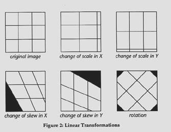
20

21 First Order Transformation
22 (RMS) Errors of Fit High order transformations (warps)

23 High order transformation
24 How much is too much? Rubber sheeting
25 When rectify Comparing pixels scene to scene in applications such as change detection Developing GIS data bases for modeling Creating accurate scaled photomaps Overlaying an image with vector data Extracting accurate distance and area measurements Mosaicking Images Disadvantages of Rectification Image must be resampled to fit into a new grid of pixel rows and columns Spectral integrity of the data can be lost during rectification An unrectified image is more spectrally correct that a rectified image
26 Coordinate Systems
27 Basic coordinate systems Represent points in two-dimensional or threedimensional space Rene Decartes ( ) introduced systems of coordinates based o orthogonal (right angle) Similar systems based on angles from baselines are often referred to a polar systems Two dimensional coordinate systems are defined with respect to a single plane, as demonstrated in the following slides.
")
28 Plane coordinate systems(cartesian) POINT
")
29 Plane coordinate systems (Cartesian) LINE
")
30 Plane coordinate systems(cartesian) DISTANCE
31 Plane coordinate systems(polar) POINT
32 Plane coordinate systems Polar to Cartesian
33 Three-dimensional systems Three-dimensional coordinate systems can be defined with respect to two orthogonal planes
34 3-D Cartesian Point
35 3-D Polar Polar Coordinate
36 3-D polar to Cartesian
37 Earth based locational reference systems Reference systems and map projections extend the ideas of Cartesian and polar coordinate systems over all or part of the earth Map projections portray the nearly spherical earth in a two-dimensional representation Earth-based reference systems are based on various models for the size and shape of the earth Earth shapes are represented in many systems by a sphere However, precise positioning reference systems are based on an ellipsoidal earth and complex gravity models.
38 Reference Ellipsoids Ellipsoidal earth models are required for precise distance and direction measurement over long distances. Ellipsoidal models account for the slight flattening of the earth at the poles. This flattening of the earth's surface results at the poles in about a twenty kilometer difference between an average spherical radius and the measured polar radius of the earth. The best ellipsoidal models can represent the shape of the earth over the smoothed, averaged sea-surface to within about onehundred meters.
.")
39 Reference ellipsoids are defined by either: semi-major (equatorial radius) and semi-minor (polar radius) axes, or the relationship between the semi-major axis and the flattening of the ellipsoid (expressed as its eccentricity).
40 Many reference ellipsoids are in use by different nations and agencies. Reference ellipsoids are identified by a name and often by a year for example, the Clarke 1866 ellipsoid is different from the Clarke 1858 and the Clarke 1880 ellipsoids.
41 Selected Reference Ellipsoids Ellipse Semi-Major Axis Flattening Airy Bessel Clarke Clarke Everest Fischer 1960 (Mercury) Fischer G R S G R S G R S Hough International Krassovsky South American WGS WGS WGS WGS
42 Geodetic Datums
43 Precise positioning must also account for irregularities in the earth's surface due to factors in addition to polar flattening. Topographic and sea-level models attempt to model the physical variations of the surface: The topographic surface of the earth is the actual surface of the land and sea at some moment in time. Aircraft navigators have a special interest in maintaining a positive height vector above this surface. Sea level can be thought of as the average surface of the oceans, though its true definition is far more complex. Specific methods for determining sea level and the temporal spans used in these calculations vary considerably. Tidal forces and gravity differences from location to location cause even this smoothed surface to vary over the globe by hundreds of meters.
44 Gravity models and geoids are used to represent local variations in gravity that change the local definition of a level surface Gravity models attempt to describe in detail the variations in the gravity field. The importance of this effort is related to the idea of leveling. Plane and geodetic surveying uses the idea of a plane perpendicular to the gravity surface of the earth which is the direction perpendicular to a plumb bob pointing toward the center of mass of the earth. Local variations in gravity, caused by variations in the earth's core and surface materials, cause this gravity surface to be irregular. Geoid models attempt to represent the surface of the entire earth over both land and ocean as though the surface resulted from gravity alone.
45 Geodetic datums define reference systems that describe the size and shape of the earth based on these various models. While cartography, surveying, navigation, and astronomy all make use of geodetic datums, they are the central concern of the science of geodesy. Hundreds of different datums have been used to frame position descriptions since the first estimates of the earth's size were made by the ancient Greeks. Datums have evolved from those describing a spherical earth to ellipsoidal models derived from years of satellite measurements. Modern geodetic datums range from flat-earth models, used for plane surveying to complex models, used for international applications, which completely describe the size, shape, orientation, gravity field, and angular velocity of the earth.
46 Different nations and international agencies use different datums as the basis for coordinate systems in geographic information systems, precise positioning systems, and navigation systems. In the United States, this work is the responsibility of the National Geodetic Survey ( Links to some of the NGS's counterparts in other nations are listed at the end of the presentation Linking geodetic coordinates to the wrong datum can result in position errors of hundreds of meters. The diversity of datums in use today and the technological advancements that have made possible global positioning measurements with sub-meter accuracies requires careful datum selection and careful conversion between coordinates in different datums. For the purposes of this lecture, reference system can be divided into two groups:. Global systems can refer to positions over much of the Earth. Regional systems have been defined for many specific areas, often covering national, state, or provincial areas.
47 Global Systems

48 Latitude, Longitude, Height The most commonly used coordinate system today is the latitude, longitude, and height system. The Prime Meridian and the Equator are the reference planes used to define latitude and longitude.
49 There are several ways to define these terms precisely. From the geodetic perspective these are: The geodetic latitude of a point is the angle between the equatorial plane and a line normal to the reference ellipsoid. The geodetic longitude of a point is the angle between a reference plane and a plane passing through the point, both planes being perpendicular to the equatorial plane. The geodetic height at a point is the distance from the reference ellipsoid to the point in a direction normal to the ellipsoid. Geodetic Latitude, Longitude, and Height

50
51 ECEF X, Y, Z Earth Centered, Earth Fixed (ECEF) Cartesian coordinates can also be used to define three dimensional positions. ECEF X, Y, and Z Cartesian coordinates define three dimensional positions with respect to the center of mass of the reference ellipsoid. The Z-axis points from the center toward the North Pole. The X-axis is the line at the intersection of the plane defined by the prime meridian and the equatorial plane. The Y-axis is defined by the intersection of a plane rotated 90 east of the prime meridian and the equatorial plane. ECEF X, Y, and Z
52
53 Earth Centered, Earth Fixed (ECEF) X, Y, Z Example NAD-83 Latitude, Longitude of 30:16:28.82 N 97:44:25.19 W is X = Y = Z =
54 Universal Transverse Mercator (UTM) Universal Transverse Mercator (UTM) coordinates define two dimensional, horizontal, positions. Each UTM zone is identified by a number UTM zone numbers designate individual 6 wide longitudinal strips extending from 80 South latitude to 84 North latitude. (Military UTM coordinate systems also use a character to designate 8 zones extending north and south from the equator, see below). UTM Zones

55
56 Each zone has a central meridian. For example, Zone 14 has a central meridian of 99 west longitude. The zone extends from 96 to 102 west longitude. UTM Zone 14
57
58 Locations within a zone are measured in meters eastward from the central meridian and northward from the equator. However, Eastings increase eastward from the central meridian which is given a false easting of 500 km so that only positive eastings are measured anywhere in the zone. Northings increase northward from the equator with the equator's value differing in each hemisphere in the Northern Hemisphere, the Equator has a northing of 0 for Southern Hemisphere locations, the Equator is given a false northing of 10,000 km Figure 15. UTM Zone 14 Example Detail Table 3. UTM Coordinate Example
59 Universal Transverse Mercator (UTM) Example NAD-83 Latitude, Longitude of 30:16:28.82 N 97:44:25.19 W is NAD-83 UTM Easting, Northing m m Zone 14 R
60 Military Grid Reference System (MGRS) The Military Grid Reference System (MGRS) is an extension of the UTM system. A UTM zone number and an additional zone character are used to identify areas 6 in east-west extent and 8 in north-south extent. A few special UTM zones do not match the standard configuration (see Figure 13) between 0 and 42 east longitude, above 72 north latitude in the area of the Greenland and Barents Seas, and the Arctic Ocean. in zones 31 and 32 between 56 and 64 north latitude including portions of the North Sea and Norway.
61 UTM zone number and character are followed by two characters designating the eastings and northings of 100 km square grid cells. Starting eastward from the 180 meridian, the characters A to Z are assigned consecutively to up to 24 strips covering 18 of longitude (characters I and O are omitted to eliminate the possibility of confusion with the numerals 1 and 0). The sequence begins again every 18. From the equator northward, the characters A to V (omitting characters I and O) are used to sequentially identify 100 km squares, repeating the sequence every 2,000 km. for odd numbered UTM easting zones, northing designators normally begin with 'A' at the equator for even numbered UTM easting zones, the northing designators are offset by five characters, starting at the equator with 'F'. South of the equator, the characters continue the pattern set north of the equator. Complicating the system, ellipsoid junctions ("spheroid junctions" in the terminology of MGRS) require a shift of 10 characters in the northing 100 km grid square designators. Different geodetic datums using different reference ellipsoids use different starting row offset numbers to accomplish this. Military Grid Reference System

62
63 For a full MGRS location, UTM zone number and character and the two grid square designators are followed by an even number of digits representing more precise easting and northing values. 2 digits give a coordinate precision of 10 km. 10 digits give a coordinate precision of 1 m. MGRS Example MGRS and UTM systems are often employed in products produced by the US National Imagery and Mapping Agency ( formerly the Defense Mapping Agency.
64 Military Grid Reference System (MGRS) Example NAD-83 Latitude, Longitude of 30:16:28.82 N 97:44:25.19 W is NAD-83 Military Grid Reference 14RPU
65 World Geographic Reference System (GEOREF) The World Geographic Reference System is used for aircraft navigation. GEOREF is based on latitude and longitude. The globe is divided into twelve bands of latitude and twenty-four zones of longitude, each 15 in extent. World Geographic Reference System Index

66
67 These 15 areas are further divided into one degree units identified by 15 characters. GEOREF 1 Grid

68
69 World Geographic Reference (GEOREF) System Example NAD-83 Latitude, Longitude of 30:16:28.82 N 97:44:25.19 W is World Geographic Reference System FJHA1516
70 Regional Systems Several different systems are used regionally to identify geographic location Some of these are true coordinate systems, such as those based on UTM and UPS systems Others, such as the metes and bounds and Public Land Survey systems describe below, simply partition space
71 Transverse Mercator Grid Systems The British National Grid (BNG) is based on the National Grid System of England, administered by the British Ordnance Survey ( The BNG has been based on a Transverse Mercator projection since the 1920s. The modern BNG is based on the Ordnance Survey of Great Britain Datum The true origin of the system is at 49 north latitude and 2 degrees west longitude. The false origin is 400 km west and 100 km north. Scale factor at the central meridian is The first BNG designator defines a 500 km square. The second designator defines a 100 km square. Figure 19. British National Grid 100 km Squares The remaining digits define 10 km, 1 km, 100 m, 10 m, and 1 m eastings and northings.

72
73 British National Grid Example OS36 Latitude, Longitude of 54:30:52.55 N 1:27:55.75 W is British National Grid NZ
74 Universal Polar Stereographic (UPS) The Universal Polar Stereographic (UPS) projection is defined above 84 north latitude and south of 80 south latitude. The eastings and northings are computed using a polar aspect stereographic projection. Zones are computed using a different character set for south and north Polar regions. North Polar Area UPS Grid South Polar Area UPS Grid

75
76 North Polar Area UPS Example NAD-83 Latitude, Longitude of 85:40:30.0 N 85:40:30.0 W is Universal Polar Stereographic ZGG

77
78 South Polar Area UPS Example NAD-83 Latitude, Longitude of 85:40:30.0 S 85:40:30.0 W is Universal Polar Stereographic ATN
79 State Plane Coordinates (SPC) State plane systems were developed in order to provide local reference systems that were tied to a national datum. In the United States, the State Plane System 1927 was developed in the 1930s and was based on the North American Datum 1927 (NAD-27). NAD-27 coordinates are in English units (feet). NAD-27 State Plane Coordinate

80
81 The State Plane System 1983 is based on the North American Datum 1983 (NAD-83). NAD-83 coordinates are metric. NAD-83 State Plane Coordinate Example While the NAD-27 State Plane System has been superceded by the NAD-83 System, maps in NAD-27 coordinates are still in use.
82 State Plane Coordinate System Example NAD-83 Latitude, Longitude of 30:16:28.82 N 97:44:25.19 W is NAD-83 Texas Central Zone State Plane Coordinates, Easting and Northing m, m
83 Most USGS 7.5 Minute Quadrangles show several coordinate system grids including latitude and longitude, UTM kilometer tic marks, and applicable State Plane coordinates. Figure 23. Three Coordinate Systems on the Austin, East USGS 7.5' Quadrangle

84
85 Each state has its own State Plane system with specific parameters and projections. Software is available for easy conversion to and from latitude and longitude. A popular public domain software package, CORPSCON is maintained by the US Army Corps of Engineers Some smaller states use a single state plane zone while larger states are divided into several zones. State plane zone boundaries often follow county boundaries. State Plane Zone Example

86
87 Two projections are used in all State Plane systems, with one exception: Lambert Conformal Conic projections are used for regions with a larger east-west than north-south extent. examples are Nebraska and Michigan Transverse Mercator projections are used for regions with a larger north-south extent. examples are New Hampshire and Illinois Some states use both projections in Florida, the Lambert Conformal Conic projection is used for the North zone while the Transverse Mercator projection is used for the East and West zones. The exception is one State Plane zone in Alaska which uses an Oblique Mercator projection for a thin diagonal area. Alaska State Plane Zone 5001
88 What is the Michigan State Plane Coordinate System? Prior to 1964, Michigan relied on a system that was based on three vertical projection zones. This system was the result of the federal government's initiative, the State Plane Coordinate System of This system, with it's vertically-oriented zones, created an unnecessarily large number of long boundaries between zones, and subdivided both the Lower and Upper Peninsulas. Today, Michigan achieves the specified limits in distortions by breaking the state into three separate horizontally-oriented projections. The entire Upper Peninsula makes up the northern zone, the northern half of the Lower Peninsula is the central zone, and the southern half of the Lower Peninsula is the southern zone. There have been two iterations of this system. The first was adopted by the Michigan Legislature in Then in 1983, the federal government made broad revisions to the entire set of state systems and published these revised standards as the State Plane Coordinate System of 1983.
89 What is the Michigan GeoRef Coordinate System? Michigan GeoRef is an alternative to the State Plane Coordinate System. But, unlike Michigan State Plane, GeoRef was designed to project the State using a single zone rather than three zones. Of course, something had to be compromised to achieve a single zone system. The Michigan State Plane System specifies that 10,000 ft. on the ground can appear as no less than 9,999 ft. and no more than 10,001 ft. (1 part in 10,000) in the projected image or map. The Michigan GeoRef System, on the other hand, allows that same 10,000 ft. to vary from 9,996 ft. to 10,004 ft. (4 parts in 10,000) in apparent length. Based on an Oblique Mercator projection with special parameters, the Michigan GeoRef System minimizes this increase in distortion by using a fundamentally different kind of map projection than is used by virtually all the State Plane Systems. The State Plane Systems make use of two basically different projection models. One of those projection methods favors regions that extend primarily north and south, and the other method favors regions that extend more in an east and west direction. This choice for states such as Tennessee (east-west) and Vermont (north-south) was easy and uncompromising. However, Michigan is an odd-shaped state, expansive in a direction angling from the southeast to the northwest. The Map Projection Model used in GeoRef is well-suited to accommodating skewed regions such as Michigan.
90 Michigan State Plane (NAD27) Projection: Lambert Conformal Conic Datum: NAD27 Ellipsoid: Modified Clarke, 1866 Equatorial Radius: Polar Radius: Standard Units: US Survey feet Standard Parallels: North 45 29' N 47 05' N Central 44 11' N 45 42' N South 42 06' N 43 40' N Origin: North 87 00' W 44 47' N Central 84 20' W 43 19' N South 84 20' W 41 30'
91 Michigan State Plane (NAD83) Projection: Lambert Conformal Conic Datum: NAD83 Ellipsoid: GRS80 Standard Units: Meters Standard Parallels: North 45 29' N 47 05' N Central 44 11' N 45 42' N South 42 06' N 43 40' N Origin: North 87 00' W 44 47' N Central 84 22' W 43 19' N South 84 22' W 41 30' N
92 Projection: Oblique Mercator Datum: NAD83 Ellipsoid: GRS80 Standard Units: Meters Scale factor at projection's center: Longitude of projection's origin: 86 00' 00" W Latitude of projection's origin: 45 18' 33" N Azimuth at center of projection: False Easting: Michigan Georef False Northing:
93 Map Projections Cylindrical projections Conic projections Azimuthal projections Miscellaneous projectionis

94

95 Cylindrical

96

97 Conical

98
99

100
101 MODIS Integerized System (10 degree tiles) 10 degree Tiles: There are 460 non-fill 10 deg. by 10 deg. tiles in the grid. The tile coordinate system starts at (0,0) (horizontal tile number, vertical tile number) in the upper left corner and proceeds rightward (horizontal) and downward (vertical). The tile in the bottom left corner is (35, 17).
 in the upper left corner and proceeds downward (vertical) and rightward (horizontal). The tile in the bottom left corner is (35, 71).")
102 MODIS Integerized System (5 degree tiles)) 5 degree Tiles The tile coordinate system starts at (0,0) (vertical tile number, horizontal tile number) in the upper left corner and proceeds downward (vertical) and rightward (horizontal). The tile in the bottom left corner is (35, 71).
103 Integerized Sinusoidal Projection References "The WMO Format for the Storage of Weather Product Information and the Exchange of Weather Product Messages in Gridded Binary Form", John D. Stackpole, Office Note 388, GRIB Edition 1, U.S. Dept. of Commerce, NOAA, National Weather Service National Meteorological Center, Automation Division, Section 1, pp. 9-12, July 1, "The Michigan Earth Grid: Description, Registration Method for SSM/I Data, and Derivative Map Projections", John F. Galntowicz, Anthony W. England, The University of Michigan, Radiation Laborartory, Ann Arbor, Michigan, Feb "Selection of a Map Grid for Data Analysis and Archival", William B. Rossow, and Leonid Garder, American Meteorological Society Notes, pp , Aug "Level-3 SeaWiFS Data Products: Spatial and Temporal Binning Algorithms", Janet W. Campbell, John M. Blaisdell, and Michael Darzi, NASA Technical Memorandum , GSFC, Volume 32, Appendix A, Jan. 13, 1995.

104
Georeferencing, Map Projections, Cartographic Concepts. -Coordinate Systems -Datum
 Georeferencing, Map Projections, Cartographic Concepts -Map Projections -Coordinate Systems -Datum Map projection is "the process of systematically transforming positions on the Earth's spherical surface
What is a Map Projection?
 What is a Map Projection? It is how we represent a three dimensional Earth on a flat piece of paper However The process of transferring information from the Earth to a map causes every projection to distort
Lecture 4. Coordinate Systems & Projections
 Lecture 4 Coordinate Systems & Projections Outline Geodesy Geoids Ellipsoids Geographic Coordinate Systems Magnetic North vs. True North Datums Projections Applying Coordinate Systems and Projections Why
Lesson 5: Map Scale and Projections
 Organizing Data and Information Lesson 5: Map Scale and Projections Map Scales Projections Information can be organized as lists, numbers, tables, text, pictures, maps, or indexes. Clusters of information
Georeferencing. Place names Postal addresses Postal codes Coordinate systems (lat/long, UTM, etc.)
") Georeferencing Georeferencing Used to describe the act of assigning locations to data or information Certain requirements include that they are: unique, have shared meaning, and are persistent through
Georeferencing Georeferencing Used to describe the act of assigning locations to data or information Certain requirements include that they are: unique, have shared meaning, and are persistent through
Map Projections. Displaying the earth on 2 dimensional maps
 Map Projections Displaying the earth on 2 dimensional maps Map projections Define the spatial relationship between locations on earth and their relative locations on a flat map Are mathematical expressions
Intro to GIS Fall 2010 Georeferencing & Map Projections
 Intro to GIS Fall 2010 Georeferencing & Map Projections SHAPE OF THE EARTH Earth's Shape Geoid: shape of earth minus topographic features (irregular due to local variations in gravity) Ellipsoid: elongated
Map projections. Rüdiger Gens
 Rüdiger Gens Coordinate systems Geographic coordinates f a: semi-major axis b: semi-minor axis Geographic latitude b Geodetic latitude a f: flattening = (a-b)/a Expresses as a fraction 1/f = about 300
NR402 GIS Applications in Natural Resources Lesson 4 Map Projections
 NR402 GIS Applications in Natural Resources Lesson 4 Map Projections From http://www.or.blm.gov/gis/ 1 Geographic coordinates Coordinates are expressed as Latitude and Longitude in Degrees, Minutes, Seconds
A PRIMER ON COORDINATE SYSTEMS Commonly Used in Michigan
 A PRIMER ON COORDINATE SYSTEMS Commonly Used in Michigan David P. Lusch, Ph.D., GISP Department of Geography Remote Sensing & GIS Research and Outreach Services Group Michigan State University September,
This week s topics. Week 6. FE 257. GIS and Forest Engineering Applications. Week 6
 FE 257. GIS and Forest Engineering Applications Week 6 Week 6 Last week Chapter 8 Combining and splitting landscape features and merging GIS databases Chapter 11 Overlay processes Questions? Next week
Outline. Shape of the Earth. Geographic Coordinates (φ, λ, z) Ellipsoid or Spheroid Rotate an ellipse around an axis. Ellipse.
 Ellipsoid or Spheroid Rotate an ellipse around an axis. Ellipse.") Map Projections Outline Geodesy and map projections Prof. D. Nagesh Kumar Department of Civil Engineering Indian Institute of Science Bangalore 560 012, India http://www.civil.iisc.ernet.in/~nagesh Shape
Map Projections Outline Geodesy and map projections Prof. D. Nagesh Kumar Department of Civil Engineering Indian Institute of Science Bangalore 560 012, India http://www.civil.iisc.ernet.in/~nagesh Shape
Shape e o f f the e Earth
 1 Coordinate Systems & Projections Coordinate Systems Two map layers are not going to register spatially unless they are based on the same coordinate system. 2 Contents Shape of the earth Datum Projections
Introduction to Geographic Information Science. Updates/News. Last Lecture. Geography 4103 / Map Projections and Coordinate Systems
 Geography 4103 / 5103 Introduction to Geographic Information Science Map Projections and Coordinate Systems Updates/News Thursday s lecture Reading discussion 1 find the readings online open questions,
WHERE ARE YOU? Maps & Geospatial Concepts Fall 2012
 WHERE ARE YOU? Maps & Geospatial Concepts Fall 2012 Where are you? Relative location I m at school Absolute Location 45 26 18.07 122 43 50.78 Datums Datums A reference surface of the Earth Used as the
WHERE ARE YOU? Maps & Geospatial Concepts Fall 2015
 WHERE ARE YOU? Maps & Geospatial Concepts Fall 2015 Where are you? Relative location I m at school Absolute Location 45 26 18.07 122 43 50.78 Where is Boston? Introducing Geodesy, Ellipsoids & Geoids Geodesy
GIST 3300 / Geographic Information Systems. Last Time. Today
 GIST 3300 / 5300 Last Time Ellipsoids and Datums Today Map Projections Map Projections Today we will build on the concepts of Geographic Coordinate Systems, Ellipsoids and Datums and add the concepts of
Projections and Coordinate Systems
 Projections and Coordinate Systems Overview Projections Examples of different projections Coordinate systems Datums Projections Overview Projections and Coordinate Systems GIS must accurately represent
ch02.pdf chap2.pdf chap02.pdf
 Introduction to Geographic Information Systems 8th Edition Karl Solutions Manual Full Download: http://testbanklive.com/download/introduction-to-geographic-information-systems-8th-edition-karl-solutions-manu
Map Projections. What does the world look like? AITOFF AZIMUTHAL EQUIDISTANT BEHRMANN EQUAL AREA CYLINDRICAL
 Map Projections What does the world look like? AITOFF AZIMUTHAL EQUIDISTANT BEHRMANN EQUAL AREA CYLINDRICAL 1 CYLINDRICAL EQUAL AREA BONNE CRASTER PARABOLIC 2 ECKERT I ECKERT III ECKERT V There are many
Understanding Projections for GIS
 Presented by John Schaeffer Juniper GIS Services, Inc. This PowerPoint is available at JuniperGIS.com Presentation Objectives To understand basic concepts on projections and coordinate systems for the
The Elements of GIS. Organizing Data and Information. The GIS Database. MAP and ATRIBUTE INFORMATION
 GIS s Roots in Cartography Getting Started With GIS Chapter 2 Dursun Z. Seker MAP and ATRIBUTE INFORMATION Data (numbers and text) store as files refer to them collectively as a database gather inform.
EnvSci360 Computer and Analytical Cartography
 EnvSci360 Computer and Analytical Cartography Lecture 3 Geodesy Map Projections, Datums, and Coordinate Systems 1 Geodesy The science of measuring and representing the shape and size of the earth, and
Map Projections & Coordinate Systems
 Map Projections & Coordinate Systems 9/7/2017 1 Why? Laying the Earth Flat Need convenient means of measuring and comparing distances, directions, areas, shapes. Traditional surveying instruments measure
Working with georeferenced data. What is georeferencing? Coordinate Systems. Geographic and Projected Coordinate System
 GIS501 Fundamentals of Geographical Information Systems (GIS) Coordinate Systems Working with georeferenced data What is georeferencing? Geographically referenced data which is, in some way, referenced
Welcome to Lesson 4. It is important for a GIS analyst to have a thorough understanding of map projections and coordinate systems.
 Welcome to Lesson 4. It is important for a GIS analyst to have a thorough understanding of map projections and coordinate systems. A GIS without coordinates would simply be a database like Microsoft Excel
Geographic coordinate systems
 1 Geographic coordinate systems In this chapter you ll learn about longitude and latitude. You ll also learn about the parts that comprise a geographic coordinate system including Spheres and spheroids
12/26/2012. Geographic Information Systems * * * * GIS (... yrezaei
 ( - Geographic Information Systems ( ( 1 2 3 Information System Data base DB IS IS DB (Knowledge ( ( (System (Information System - (Georefrence Analysis Data + Knowledge ======== Information 4 5 ( < 10%
1. Geospatial technology rarely links geospatial data to nonspatial data. a. True *b. False
 Chapter 2 Where in the Geospatial World Are You? 1. Geospatial technology rarely links geospatial data to nonspatial data. 2. For geospatial technology to work, every location on Earth must be: a. inhabited
Projections & GIS Data Collection: An Overview
 Projections & GIS Data Collection: An Overview Projections Primary data capture Secondary data capture Data transfer Capturing attribute data Managing a data capture project Geodesy Basics for Geospatial
GEOGRAPHIC COORDINATE SYSTEMS
 GEOGRAPHIC COORDINATE SYSTEMS Introduction to GIS Winter 2015 What is Georeferencing? Used to establish a location on the Earth s surface 1 st order polynomial transformation Georeferencing toolbar What
Military Map Reading 201
 Military Map Reading 201 This information paper is designed to resolve the confusion between the Universal Transverse Mercator (UTM) and the Military Grid Reference System (MGRS) coordinates. The two systems
Lecture 10-14: Map Projections and Coordinate System
 URP 1281 Surveying and Cartography Lecture 10-14: Map Projections and Coordinate System December 27, 2015 Course Teacher: Md. Esraz-Ul-Zannat Assistant Professor Department of Urban and Regional Planning
The Wildlife Society Meet and Greet. Come learn about what the UNBC Student Chapter of TWS is all about!
 Georeferencing I GEOG 300, Lecture 4 Dr. Anthony Jjumba 1 The Wildlife Society Meet and Greet Quiz Come learn about what the UNBC Student Chapter of TWS is all about! 5:30 7:30 PM, Wednesday September
Geo Referencing & Map projections CGI-GIRS 0910
 Geo Referencing & Map projections CGI-GIRS 0910 Where are you? 31UFT8361 174,7 441,2 51 58' NB 5 40' OL 2/60 Who are they? 3/60 Do geo data describe Earth s phenomena perfectly? Georeference systems ellipsoid
Georeferencing. datum. projection. scale. The next few lectures will introduce you to these elements. on the Earth, you ll need to understand how
 Georeferencing GOAL: To assign a location to all the features represented in our geographic information data In order to do so, we need to make use of the following elements: ellipsoid/geoid To determine
Applied Cartography and Introduction to GIS GEOG 2017 EL. Lecture-1 Chapters 1 and 2
 Applied Cartography and Introduction to GIS GEOG 2017 EL Lecture-1 Chapters 1 and 2 What is GIS? A Geographic Information System (GIS) is a computer system for capturing, storing, querying, analyzing and
How does an ellipsoid differ from a sphere in approximating the shape and size of the Earth?
 Chapter 02 Test Bank Worksheet Questions 1. What is a map projection? Topic: Map Projection 2. How does an ellipsoid differ from a sphere in approximating the shape and size of the Earth? Topic: Ellipsoid
GPS Remote Sensing. GIS Photogrammetry. GEODESY Equipment (total station) CARTOGRAPHY Survey Software. Map Projection Coordinate Systems
 CARTOGRAPHY Survey Software. Map Projection Coordinate Systems") GPS Remote Sensing GIS Photogrammetry GEODESY Equipment (total station) CARTOGRAPHY Survey Software Map Projection Coordinate Systems 1 Coordinate Systems, Datum and Map Projection Dr. Maher A. El-Hallaq
GPS Remote Sensing GIS Photogrammetry GEODESY Equipment (total station) CARTOGRAPHY Survey Software Map Projection Coordinate Systems 1 Coordinate Systems, Datum and Map Projection Dr. Maher A. El-Hallaq
Chapter 3 Geographic Location Systems
 Chapter 3 Geographic Location Systems In this chapter you will learn about: Latitude and longitude Universal Transverse Mercator (UTM) U.S. Public Land Survey Other geographic location systems Geographic
Geo Referencing & Map projections CGI-GIRS 0910
 Geo Referencing & Map projections CGI-GIRS 0910 Where are you? 31UFT8361 174,7 441,2 51 58' NB 5 40' OL 2/60 Who are they? 3/60 Do geo data describe Earth s phenomena perfectly? Georeference systems ellipsoid
Overview key concepts and terms (based on the textbook Chang 2006 and the practical manual)
") Introduction Geo-information Science (GRS-10306) Overview key concepts and terms (based on the textbook 2006 and the practical manual) Introduction Chapter 1 Geographic information system (GIS) Geographically
Introduction Geo-information Science (GRS-10306) Overview key concepts and terms (based on the textbook 2006 and the practical manual) Introduction Chapter 1 Geographic information system (GIS) Geographically
HP-33S Calculator Program TM 2
 Convert Latitude and Longitude to Transverse Mercator Co-ordinates (UTM, SPCS, etc.) Programmer: Dr. Bill Hazelton Date: April, 2008. Version: 1.0 Mnemonic: T for Transverse Mercator Line Instruction Display
Importance of Understanding Coordinate Systems and Map Projections.
 Importance of Understanding Coordinate Systems and Map Projections. 1 It is extremely important that you gain an understanding of coordinate systems and map projections. GIS works with spatial data, and,
Control Surveys and Coordinate Systems
 Control Surveys and Coordinate Systems The Earth is Round Basic Shape of the Earth: Oblate Spheroid of Revolution The length of the equatorial axis is approximately 27 miles greater than the polar axis.
Geographers Perspectives on the World
 What is Geography? Geography is not just about city and country names Geography is not just about population and growth Geography is not just about rivers and mountains Geography is a broad field that
Notes on Projections Part II - Common Projections James R. Clynch February 2006
 Notes on Projections Part II - Common Projections James R. Clynch February 2006 I. Common Projections There are several areas where maps are commonly used and a few projections dominate these fields. An
2. Which geometric model has been used at some time to describe the earth? a. Sphere b. Oblate ellipsoid c. Flat disk. d. Geoid e.
 01 02 03 04 05 06 07 08 09 10 11 12 13 14 15 16 17 18 19 20 21 22 23 24 25 26 27 28 29 30 31 32 33 34 35 36 37 38 39 40 41 42 43 44 45 46 47 48 49 50 Geography 12 Sample Mid-Term Examination Before you
Analytical and Computer Cartography Lecture 3: Review: Coordinate Systems
 Analytical and Computer Cartography Lecture 3: Review: Coordinate Systems Geographic Coordinates NAD83 NAD27 remained in use until the earthcentered international GRS80 was complete (Geodetic Reference
HP-35s Calculator Program Lambert 1
 Convert Latitude and Longitude to Lambert Conformal Conic Projection Co-ordinates (SPCS) Programmer: Dr. Bill Hazelton Date: July, 2010. Version: 1.2 Line Instruction Display User Instructions N001 LBL
REFERENCING COORDINATE SYSTEMS MAP PROJECTIONS GEOREFERENCING
 GIS in Ecology SPATIAL REFERENCING COORDINATE SYSTEMS MAP PROJECTIONS GEOREFERENCING : :1 Where on earth? Early mapmakers recognized the need for a system that could locate features on the earth's surface.
The Nature of Spatial Data. Keith C. Clarke Geography UCSB
 The Nature of Spatial Data Keith C. Clarke Geography UCSB Geographic primitives G = g (x, y, z, s, A, t) [x, y, z] = f(λ, φ, d) Geography also highly dependent upon model First, the datum (d) Models of
Dr. ABOLGHASEM AKBARI Faculty of Civil Engineering & Earth Resources, University Malaysia Pahang (UMP)
") Workshop on : Dr. ABOLGHASEM AKBARI Faculty of Civil Engineering & Earth Resources, University Malaysia Pahang (UMP) 14-15 April 2016 Venue: Tehran, Iran GIS definitions GIS: A simplified view of the real
Workshop on : Dr. ABOLGHASEM AKBARI Faculty of Civil Engineering & Earth Resources, University Malaysia Pahang (UMP) 14-15 April 2016 Venue: Tehran, Iran GIS definitions GIS: A simplified view of the real
Projections Part I - Categories and Properties James R. Clynch February 2006
 I. Introduction and References Projections Part I - Categories and Properties James R. Clynch February 2006 The world is, approximately, a sphere. Maps are flat. Making maps requires some method of putting
Spatial Reference Systems. Introduction
 Spatial Reference Systems Wolfgang Kainz Professor of Cartography and Geoinformation Department of Geography and Regional Research University of Vienna wolfgang.kainz@univie.ac.at Introduction Historic
BUILDING AN ACCURATE GIS
 BUILDING AN ACCURATE GIS 2006 GIS in the Rockies Denver, Colorado September 13, 2006 William E. Linzey United States Department of Commerce National Oceanic and Atmospheric Administration National Geodetic
HP-35s Calculator Program TM 1
 Convert Latitude and Longitude to Transverse Mercator Co-ordinates (UTM, SPCS, etc.) Programmer: Dr. Bill Hazelton Date: April, 2008. Version: 1.0 Mnemonic: T for Transverse Mercator Line Instruction Display
1/28/16. EGM101 Skills Toolbox. Oblate spheroid. The shape of the earth Co-ordinate systems Map projections. Geoid
 EGM101 Skills Toolbox Oblate spheroid The shape of the earth Co-ordinate systems Map projections The geoid is the shape that the surface of the oceans would take under the influence of Earth's gravitation
Lecture 2. Map Projections and GIS Coordinate Systems. Tomislav Sapic GIS Technologist Faculty of Natural Resources Management Lakehead University
 Lecture 2 Map Projections and GIS Coordinate Systems Tomislav Sapic GIS Technologist Faculty of Natural Resources Management Lakehead University Map Projections Map projections are mathematical formulas
Plane coordinates ~~~~~~~~~~
 Coordinate Systems & Map Projections Geographic coordinates A Basic Introduction to Coordinate Systems & Map Projections Latitude & longitude Angles Parallels & meridians Lines Plane coordinates ~~~~~~~~~~
Coordinate Systems. Location on earth is defined by coordinates
 Coordinate Systems We think of the earth as a sphere It is actually a spheroid (ellipsoid), slightly larger in radius at the equator than at the poles Shape of the Earth Location on earth is defined by
Map projections. Rüdiger Gens
 Rüdiger Gens 2 Outline! Relevant terms! Why map projections?! Map projection categories " Projection surfaces " Features preserved from distortions! Map projection examples! Right choice Relevant terms!
2. GETTING STARTED WITH GIS
 2. GETTING STARTED WITH GIS What are geographic information systems and what are they used for? ArcGIS: ArcMap, ArcCatalog and ArcToolbox Vector data vs. raster data vs. attribute tables Polygons, polylines,
Map Projections 2/4/2013. Map Projections. Rhumb Line (Loxodrome) Great Circle. The GLOBE. Line of constant bearing (e.g., 292.
 Great Circle. The GLOBE. Line of constant bearing (e.g., 292.") The GLOBE ADVANTAGES Directions True Distances True Shapes True Area True DISADVANTAGES Very small scale with little detail. Costly to reproduce and update. Difficult to carry around. Bulky to store. FACTS
The GLOBE ADVANTAGES Directions True Distances True Shapes True Area True DISADVANTAGES Very small scale with little detail. Costly to reproduce and update. Difficult to carry around. Bulky to store. FACTS
Lab #3 Map Projections.
 Lab #3 Map Projections http://visual.merriam-webster.com/images/earth/geography/cartography/map-projections.jpg Map Projections Projection: a systematic arrangement of parallels and meridians on a plane
Map Projections & Coordinate Systems 1/25/2018
 Map Projections & Coordinate Sstems Laing the Earth Flat How? Projections transformation of curved earth to a flat map; sstematic rendering of the lat. & lon. graticule to rectangular coordinate sstem.
Modern Navigation. Thomas Herring
 12.215 Modern Navigation Thomas Herring Today s Class Latitude and Longitude Simple spherical definitions Geodetic definition: For an ellipsoid Astronomical definition: Based on direction of gravity Relationships
Modern Navigation. Thomas Herring
 12.215 Modern Navigation Thomas Herring Today s class Map Projections: Why projections are needed Types of map projections Classification by type of projection Classification by characteristics of projection
Mapping coordinate systems
 Mapping coordinate systems 1. The Earth's Graticule Latitude and Longitude The graticule is the imaginary grid of lines running east-west (lines of latitude = parallels) and north-south lines of longitude
Fundamentals of Surveying (LE/ESSE )
") Fundamentals of Surveying (LE/ESSE 2620 3.0) Lecture 2 Basics of Surveying Dr.-Ing. Jian-Guo Wang Geomatics Engineering York University Fall 2017 1 2-1. Overview Part 1: Basics - The Earth s Shape & Size.
Fundamentals of Surveying (LE/ESSE 2620 3.0) Lecture 2 Basics of Surveying Dr.-Ing. Jian-Guo Wang Geomatics Engineering York University Fall 2017 1 2-1. Overview Part 1: Basics - The Earth s Shape & Size.
Map Projections & Coordinate Systems 9/10/2013. Why? M. Helper GEO327G/386G, UT Austin 2. M. Helper GEO327G/386G, UT Austin 4
 Map Projections & Coordinates Laing the earth flat Wh? Need convenient means of measuring and comparing distances, directions, areas, shapes. Traditional surveing instruments measure in meters or feet,
Map Projections & Coordinate Systems 9/7/2017
 Map Projections & Coordinate Sstems Laing the Earth Flat Wh? Need convenient means of measuring and comparing distances, directions, areas, shapes. Traditional surveing instruments measure in meters or
GIS in Water Resources. Fall Homework #1
 GIS in Water Resources Fall 2015 Homework #1 Goal The goal of this homework is to reinforce the lecture material on Geodesy, Map Projections and Coordinate Systems by having you identify attributes and
Georeferencing. Where on earth are we? Critical for importing and combining layers for mapping
 Georeferencing Where on earth are we? Critical for importing and combining layers for mapping 1. The Geoid Earth is not a perfect sphere, it is ellipsoidal.. earth is the 'Geoid'. The difference between
Boolean Operators and Topological OVERLAY FUNCTIONS IN GIS
 Boolean Operators and Topological OVERLAY FUNCTIONS IN GIS Query asking a question of the attribute data Standard Query Language (SQL) is used to query the data There are 4 basic statements used to get
Referencing map features: Coordinate systems and map projections
 Referencing map features: Coordinate systems and map projections Coordinate systems and map projections if we want to integrate geographic data from many different sources, we need to use a consistent
4 Survey Datums. 4.1 Horizontal Datum Policy SURVEY DATUMS SEPTEMBER 2006
 4 Survey Datums Today s multi-organizational Project Development efforts require the use of common, accurate horizontal and vertical survey datums and consistent, precise control-survey procedures to ensure
Watershed Sciences 4930 & 6920 GEOGRAPHIC INFORMATION SYSTEMS
 Watershed Sciences 4930 & 6920 GEOGRAPHIC INFORMATION SYSTEMS WEEK TWO Lecture PROJECTIONS Joe Wheaton Some of slides in this lecture adapted from content in Paul Bolstad s Fundamentals of GIS HOUSEKEEPING
HP-35s Calculator Program Lambert 2
 Convert Lambert Conformal Conic Projection Co-ordinates (SPCS) to Latitude and Longitude Programmer: Dr. Bill Hazelton Date: September, 2010. Version: 1.1 Mnemonic: L for Lambert to Latitude and Longitude
Lecture 9: Reference Maps & Aerial Photography
 Lecture 9: Reference Maps & Aerial Photography I. Overview of Reference and Topographic Maps There are two basic types of maps? Reference Maps - General purpose maps & Thematic Maps - maps made for a specific
Georeferencing. Geography is the key to linking attributes. Georeferencing is the key to geography.
 Georeferencing Geography is the key to linking attributes. Georeferencing is the key to geography. Why georeferencing? Many reasons for having georeferences Many different approaches to georeferencing
Watershed Sciences 4930 & 6920 GEOGRAPHIC INFORMATION SYSTEMS
 PROJECTS Watershed Sciences 4930 & 6920 GEOGRAPHIC INFORMATION SYSTEMS WEEK THREE Lecture 5 PROJECT DATA/IDEAS, PROJECTIONS (Cont.) & LAB REVIEW Joe Wheaton GUEST LECTURE HOUSEKEEPING: LAB 01 GRADES This
Geodetics: Implications for GIS Professionals May 10, 2018
 Experts in Geomatics, Surveying, Positioning, Geospatial Data, and Mapping Sciences Geodetics: Implications for GIS Professionals May 10, 2018 Michael Barnes APSG Education Foundation Chair 2010-2020 APSG
The 3-D Global Spatial Data Model: Geometrical Foundation of the Global Spatial Data Infrastructure
 The 3-D Global Spatial Data Model: Geometrical Foundation of the Global Spatial Data Infrastructure Earl F. Burkholder, PS, PE Annotated Table of Contents July 8,2006 I. The Global Spatial Data Model (GSDM)
Ground Truth Annual Conference. Optimized Design of Low Distortion Projections. Michael L. Dennis, RLS, PE
 Arizona Professional Land Surveyors Association 016 Annual Conference Ground Truth Optimized Design of Low Distortion Projections Michael L. Dennis, RLS, PE Version 3 (rev 1), May 016 Design and metadata
Fri. Jan. 26, Demonstration of QGIS with GPS tracks. Types of data, simple vector (shapefile) formats
 formats") Fri. Jan. 26, 2018 Demonstration of QGIS with GPS tracks Types of data, simple vector (shapefile) formats Map projections, Coordinate Reference Systems Demonstration of QGIS with geologic map 1 Raster
Fri. Jan. 26, 2018 Demonstration of QGIS with GPS tracks Types of data, simple vector (shapefile) formats Map projections, Coordinate Reference Systems Demonstration of QGIS with geologic map 1 Raster
Data acquisition and integration 1.
 Data acquisition and integration 1. Ferenc Végső Data acquisition and integration 1.: Ferenc Végső Lector: Árpád Barsi This module was created within TÁMOP - 4.1.2-08/1/A-2009-0027 "Tananyagfejlesztéssel
Lab 1: Importing Data, Rectification, Datums, Projections, and Coordinate Systems
 Lab 1: Importing Data, Rectification, Datums, Projections, and Coordinate Systems Topics covered in this lab: i. Importing spatial data to TAS ii. Rectification iii. Conversion from latitude/longitude
Hydrology and Floodplain Analysis, Chapter 10
 Hydrology and Floodplain Analysis, Chapter 10 Hydrology and Floodplain Analysis, Chapter 10.1 Introduction to GIS GIS Geographical Information System Spatial Data Data linked with geographical location
GeoMag USING GEOMAG 2 UTM COORDINATE SYSTEM 4 GEODETIC DATUMS AND ELLIPSOIDS 11 A BRIEF INTRODUCTION TO GEOMAGNETISM 14 EARTH MAGNETIC FIELD MAPS 16
 GeoMag USING GEOMAG 2 UTM COORDINATE SYSTEM 4 GEODETIC DATUMS AND ELLIPSOIDS 11 A BRIEF INTRODUCTION TO GEOMAGNETISM 14 EARTH MAGNETIC FIELD MAPS 16 ABOUT GEOMAG 18 1 Using GeoMag GeoMag is a very simple
ENV101 EARTH SYSTEMS
 ENV101 EARTH SYSTEMS Practical Exercise 2 Introduction to ArcMap and Map Projections 1. OVERVIEW This practical is designed to familiarise students with the use of ArcMap for visualising spatial data and
P R O J E C T I O N S. Map Projections. Introduction to. Map Projections. with. TNTmips. TNTedit TNTview. page 1
 P R O J E C T I O N S Introduction to Map Projections Map Projections with TNTmips page 1 TNTedit TNTview Before Getting Started Positions in a georeferenced spatial object must refer to a particular coordinate
VT State Plane. Daniel J. Martin National Geodetic Survey VT Geodetic Advisor. VSLS Conference Rutland VT April 11, 2008
 VT State Plane Daniel J. Martin National Geodetic Survey VT Geodetic Advisor VSLS Conference Rutland VT April 11, 2008 Today s Outline Define the problem Review of VT State Plane System Relationship
FM Map Reading and Land Navigation
 FM 3-25.26 Map Reading and Land Navigation CHAPTER 4 GRIDS This chapter covers how to determine and report positions on the ground in terms of their locations on a map. Knowing where you are (position
Height systems. Rudi Gens Alaska Satellite Facility
 Rudi Gens Alaska Satellite Facility Outline Why bother about height systems? Relevant terms Coordinate systems Reference surfaces Geopotential number 2 Why bother about height systems? give a meaning to
The Earth is a Rotating Sphere
 The Earth is a Rotating Sphere The Shape of the Earth Earth s Rotation ( and relative movement of the Sun and Moon) The Geographic Grid Map Projections Global Time The Earth s Revolution around the Sun
Introduction to Cartography GEOG 2016 E. Lecture-2 Geodesy and Projections
 Introduction to Cartography GEOG 2016 E Lecture-2 Geodesy and Projections What is Geodesy? The science of geodesy determines: Earth s shape and Interrelation of different points on earth s surface The
When the Earth Was Flat. Measurements were made using a plumb bob, a spirit level, and a stick. Also, the Stars.
 ABSTRACT Defining the shape of the Earth geoid. Mathematical models spheroid or ellipsoid Mathematical projection of geodetic systems GIS/GPS technology The need for a unified projection systems World
Geog Lecture 29 Mapping and GIS Continued
 Geog 1000 - Lecture 29 Mapping and GIS Continued http://scholar.ulethbridge.ca/chasmer/classes/ Today s Lecture (Pgs 13-25, 28-29) 1. Hand back Assignment 3 2. Review of Dr. Peddle s lecture last week
Data acquisition and integration 1.
 University of West Hungary, Faculty of Geoinformatics Ferenc Végső Data acquisition and integration 1. module DAI1 The basics of positioning SZÉKESFEHÉRVÁR 2010 The right to this intellectual property