Factors affecting MFI membrane quality
|
|
|
- Ethel Hopkins
- 5 years ago
- Views:
Transcription
1 2007:41 DOCTORAL T H E SIS Factors affecting MFI membrane quality Charlotte Andersson Luleå University of Technology Department of Chemical Engineering and Geosciences Division of Chemical Technology 2007:41 ISSN: ISRN: LTU-DT SE
2
3 Doctoral thesis Factors affecting MFI membrane quality Charlotte Andersson September 2007 Chemical Technology Chemical Engineering and Geosciences Luleå University of Technology
4
5 Abstract Zeolites are crystalline aluminosilicates with molecular sieving properties and are widely used in industrial applications such as catalysis, sorption and ion-exchange. Zeolite membranes are highly interesting due to their capability to continuously separate molecules under severe conditions. The MFI zeolite structure has suitable pore diameter for many applications, and its thermal and chemical stability is high. In order to obtain high performance MFI membranes, a thin and defect free film is needed for high flux and high selectivity. In this thesis, parameters affecting quality of zeolite membranes have been investigated. Different MFI-zeolite membranes were prepared using seed crystals and hydrothermal synthesis. Thereafter, membranes were characterized using scanning electron microscopy, single gas permeation measurements, porosimetry and separation experiments. The effect of grain boundaries was investigated by preparing membranes with small crystal size. It was found that a high amount of grain boundaries reduced the quality of the membranes. In another study, the effect of exposure to aqueous solutions was found to increase the amount of non-zeolitic pores in the membrane, and thus it decreased the quality of the membrane. However, no such effect was found for ethanol that was identified as a safe rinsing media. Membranes with different Si/Al ratio were also prepared and evaluated. It was observed that the Si/Al ratio of a MFI membrane influences the performance of the membrane. It was found that an increase of aluminium makes the membrane more polar which leads to an improved adsorption of, and selectivity for polar molecules. The effect of support invasion was also evaluated and the regularity and extension of the support invasion was observed to affect membrane quality. The effect of heating rate during calcination was investigated and no correlation between heating rate and membrane quality was observed. Calcination of membranes was studied in-situ by high temperature synchrotron radiation and a model for crack formation was postulated. In summary, this work has shown that in order to obtain high quality membranes, the amount of grain boundaries, the film thickness and support invasion should be controlled.
6 To obtain the best performance of the membranes the Si/Al ratio should be chosen with respect to the application. Finally, water exposure affects the lifetime of the MFI membranes in certain applications.
7 Acknowledgements First of all, I would like to thank my supervisor Professor Jonas Hedlund, for being so enthusiastic and for never getting weary. Your ideas, encouragement and support made this work possible. To my previous co-supervisor Dr. Fredrik Jareman, thank you for your encouraging support, help and our cooperation. Thank you, Lic. Eng. Jonas Lindmark for our cooperation and discussions concerning research and experimental problems. Thank you all cooperation partners, especially Dr. Magdalena Lassinantti Gaultieri and M. Sc. Seyed Alireza Sadat Rezai for fruitful cooperation s. Thank you to all the people at the division of Chemical Technology: Dr. Mattias Grahn, M. Sc. Alessandra Mosca, M. Sc. Linda Stenberg, M. Sc. Ivan Carabante, M. Sc. Elisaveta Potapova and Mr. Olle Niemi for all help and laughter s. A special thank you also to Mrs Maine Ranheimer for always giving a helping hand in the lab! The people at the department of Chemical Engineering and Geosciences are all acknowledged for creating a nice working atmosphere. I would also like to say thank you to Professor Roland Larsson, the initiator of Research Trainee, where my Ph.D. studies started. The Swedish Research Council (VR) is gratefully acknowledged for its financial support. Many hugs to my family and all my friends for supporting me! And finally the biggest thank you goes to Peter for being able to live with a true pessimist.
8
9 List of papers This thesis is based on the following seven papers, referred to in the text by their Roman number. I II III IV V Support invasion and quality in silicalite-1 membranes, Charlotte Andersson and Jonas Hedlund, Manuscript in preparation Effects of exposure to water and ethanol on silicalite-1 membranes, Charlotte Andersson, Fredrik Jareman and Jonas Hedlund, Submitted to Journal of Membrane Science Water/hydrogen/hexane multicomponent selectivity of thin MFI membranes with different Si/Al ratio, Seyed Alireza Sadat Rezai, Jonas Lindmark, Charlotte Andersson, Fredrik Jareman, Klaus Möller and Jonas Hedlund, Microporous and Mesoporous Materials, In press Crack formation in -alumina supported MFI zeolite membranes studied by in-situ High Temperature Synchrotron Powder Diffraction, Magdalena Lassinantti Gualtieri, Charlotte Andersson, Fredrik Jareman, Jonas Hedlund, Alessandro F. Gualtieri, Matteo Leoni and Carlo Meneghini, Journal of Membrane Science, Volume 290, Issues 1-2, 1 March 2007, Pages The influence of calcination rate on Silicalite-1 membranes, Fredrik Jareman, Charlotte Andersson and Jonas Hedlund, Microporous and Mesoporous Materials, Volume 79, Issues 1-3, 1 April 2005, Pages 1-5 VI Silicalite-1 membranes with small crystal size, Charlotte Andersson, Jonas Hedlund, Fredrik Jareman and Johan Sterte, Studies in Surface Science and
10 Catalysis, Recent advances in the science and technology of zeolites and related materials, Volume 154, part 1, 2004, Pages VII Factors affecting the performance of MFI membranes, Jonas Hedlund, Fredrik Jareman and Charlotte Andersson, Studies in Surface Science and Catalysis, Recent advances in the science and technology of zeolites and related materials, Volume 154, part 1, 2004, Pages My contribution to the appended papers: I II III IV V VI VII All planning, experimental work and evaluation, most of the writing, All planning and experimental work, most of the evaluation and writing. Part of the planning, experimental work and evaluation. Part of the planning, experimental work, evaluation and writing, I did not take part in the Rietveld refinement analysis Part of the planning, experimental work, evaluation and writing. All experimental work, most of the evaluation and writing, participated in the planning. Part of the experimental work and evaluation for the work concerning film thickness and calcination.
11 Contents 1 INTRODUCTION BACKGROUND SCOPE OF THE PRESENT WORK MOLECULAR SIEVES AND ZEOLITES AN INTRODUCTION TO MOLECULAR SIEVES AND ZEOLITES MFI ZEOLITE PREPARATION OF MFI ZEOLITE SI/AL RATIO ALKALINE AND ACID TREATMENT ZEOLITE MEMBRANES SEPARATION IN ZEOLITE MEMBRANES PROPERTIES OF MFI MEMBRANES Crystal orientation Defects Grain boundaries Crack formation due to thermal expansion Support invasion PERMEATION MEASUREMENTS EXPERIMENTAL MEMBRANE PREPARATION CHARACTERIZATION Scanning electron microscopy X-ray diffraction Permeation measurements RESULTS AND DISCUSSION GENERAL PROPERTIES OF THE MEMBRANES PREPARED IN THIS WORK Si/Al ratio...25
12 5.2 PARAMETERS AFFECTING MFI MEMBRANE MORPHOLOGY Crystal size Exposure to ethanol and aqueous solutions Thermal expansion during calcination Support invasion PARAMETERS AFFECTING MFI MEMBRANE PERFORMANCE Open grain boundaries Calcination rate Support invasion Si/Al ratio Film thickness CONCLUSIONS FUTURE WORK...45 REFERENCES...47 APPENDED PAPERS 2
13 1 Introduction 1.1 Background Zeolites are porous crystalline aluminosilicates and are widely used in applications such as catalysts in the refining of petroleum or as ion exchangers in detergents. Zeolite membranes are commercially interesting due to the potential ability to separate molecules in continuous processes in industry. Advantages compared to other membrane types are high flux and selectivity due to well-defined pores and thermal and chemical stability. In high quality membranes the zeolite film must be thin for high flux and free from defects for high selectivity. To achieve high quality membranes, parameters controlling the properties of zeolite membranes must be understood. 1.2 Scope of the present work In the present work, the influence of various parameters on quality of MFI type zeolite membranes is investigated. The aim is to understand how these parameters and processes effect membrane morphology and/or performance, and thus the quality of MFI membranes. The effect of the following parameters and processes were investigated: Crystal size in the film Exposure to aqueous solutions and ethanol Zeolite deposition in the support pores, so called support invasion The thermal expansion during calcination Calcination rate Si/Al ratio in the MFI film Film thickness 3
14
15 2 Molecular Sieves and Zeolites 2.1 An introduction to molecular sieves and zeolites A molecular sieve is a material that can separate molecules based on size and shape. A subgroup of molecular sieves is zeolites. Zeolites are natural and synthetic microporous aluminosilicates. The Swede Cronstedt reported for the first time about this new class of minerals in the 18 th century and denoted it zeolites from the Greek word zeo and litos which means a boiling stone [1, 2]. The zeolite framework is a three-dimensional network of oxygen ions with either Si 4+ or Al 3+ situated in the tetrahedral sites. This framework may be described with the following formula: M 2 / n O Al 2 O 3 xsio 2 yh 2 O [2] M: exchangeable cation for example Li +, Na + + or NH 4 n: cation valance y: degree of hydration All known zeolite frameworks have been assigned with a three-letter code. Today there are more than 170 known framework structures [3]. For a given framework, the chemical composition can be varied significantly by varying Si/Al ratio and cations. Zeolites can also be depicted as a network of channels were the dimensions of the channel openings varies from zeolite to zeolite, ranging from 3 to 13 Å [2]. Zeolites are used in applications in primarily three areas; adsorption, catalysis and ion exchange. The most common 5
![application for zeolites is as water softener in detergents. Other applications are gas separation and as catalysts in the refining of petroleum [4, 5].](/docs-images/88/114875478/images/16-0.jpg "Zeolites are commonly prepared by hydrothermal treatment. The synthesis mixture mostly contains water, a silica source, an alumina source, a mineralizing agent and a templating agent.")

16 application for zeolites is as water softener in detergents. Other applications are gas separation and as catalysts in the refining of petroleum [4, 5]. Zeolites are commonly prepared by hydrothermal treatment. The synthesis mixture mostly contains water, a silica source, an alumina source, a mineralizing agent and a templating agent. The synthesis mixture is heated and the composition of the synthesis solution, synthesis time and synthesis temperature determines which zeolite that will crystallize. To remove the templating agent, the zeolite must be calcined after synthesis; a procedure where the zeolite is heated in air to decompose and burn the templating agent that is blocking the pores. 2.2 MFI zeolite Figure 1 shows a MFI crystal with typical habit and pore geometry of the structure. MFI is one of the most commonly prepared zeolites and today the second most used structure in catalytic applications [6]. MFI zeolite is often used to prepare membranes due to suitable pore diameter and a relatively high thermal and chemical stability [7]. Figure 1. MFI crystal with typical coffin habit. The channel system with the pore openings (nm) running in two directions is shown. The pore network consists of straight pores running in the b-direction and zigzag pores in the a-direction. This network also allows a molecule to move in the c-direction. The two different molecular sieves ZSM-5 and silicalite-1 both have the MFI structure. Silicalite-1 is an all silica zeolite and ZSM-5 has a Si/Al ratio down to 10 [2]. 6
17 2.3 Preparation of MFI zeolite Formation of MFI crystals is believed to be a complex process consisting of several different independent processes [8]. It can basically be viewed as pre-nucleation, nucleation and continued crystal growth. One possible process was presented by Schoeman [9] for the crystallization of silicalite-1 from a clear solution with TEOS as the silica source. In this case, the first step is hydrolysis of TEOS to form a silicate suspension with various silicate species, of which certain of these subcolloidal particles can be considered as nuclei. The silicate particles subsequently grow with an increase in temperature and by the supply of nutrients such as monomeric enclathered species. The templating agent used to synthesize MFI for the first time was TPA + [10], a structure directing agent that promotes the formation of MFI over a wide range of chemical compositions [2, 8]. It is the charge, hydrophobicity and geometry of TPA + that leads to a promotion of nuclei formation. Other organic ions such as TMA + and TEA + can also be used to crystallize the MFI structure, but the compositional range in which MFI will form will not be as wide as with the TPA template. The selection and amount of organic molecules will also vary the morphology of the final crystal [8, 10]. The alkalinity also affects the crystallisation and in general an increase in alkalinity will lead to an increase in crystal growth rate [8]. In the case of some aluminosilicate solutions, an increase in alkalinity (above a certain threshold value) will lead to a lowered growth rate [8, 11]. For silicalite-1 particles, the increase in alkalinity (in this case TPAOH) will increase the number of particles and hence the particle size, but it will not decrease the growth rate [12]. The relationship between silica and alumina in a synthesis solution will determine which structure that will form and will also influence the Si/Al ratio of the structure formed. An increase in alumina in the synthesis solution was found to decrease the crystal growth rate and the number of particles and hence increase the crystal size [11]. 2.4 Si/Al ratio The Si/Al ratio in a zeolite will affect its properties in several ways. The introduction of alumina in the structure will result in acidity and a zeolite that can be used in catalytic applications. The alumina content also determines the hydrophobicity of the zeolite, an alumina rich structure would be more hydrophilic [13] and hence more adopted for applications were the adsorption of polar molecules could be of use, for example waterorganic separations. The effects of introducing aluminium in the structure is thus believed to change the performance of the membrane [14, 15]. The increase in alumina also makes the zeolite less stable and the resistance towards acids also decreases [2]. To change the Si/Al ratio in a zeolite, dealumination and desilication can be used. In acid dealumination, the aluminium is removed without seriously affecting the crystal structure 7
18 but affecting the acidity of the zeolite [16]. Desilication is the removal of silica from the zeolite framework by an alkaline treatment and was first performed to study the changes in the crystal when in contact with an alkaline media [17]. 2.5 Alkaline and acid treatment The dissolution behaviour of zeolites is quite complex and will depend on the zeolite in question and the Si/Al ratio. Amorphous silica reaches a solubility minima at ph 7-8 and is thus soluble in both acids and bases but the solubility is substantially higher in bases [18]. The dissolution rate will also increase with increasing ph [18]. It is well-known that the alumina rich phases in natural zeolites are sensitive to acids [2] and in zeolites, alumina is also preferentially released at low ph [19, 20]. At higher ph, the dissolution of silica appears to be controlling the dissolution rate. In general the dissolution kinetics of zeolites over larger ph-ranges follow a clear u-trend with a high dissolution rate at low ph followed by a minimum in near neutral solutions and then an increase again with ph [19, 21]. The alumina content does not only affect the dissolution behaviour in acids, it has also been found to have an effect on the dissolution in bases. A high concentration of alumina in the zeolite stabilizes the structure and decreases the dissolution of silica at high ph [22]. The increase of porosity in the zeolite, when in contact with an alkaline media, has been reported in several publications. Groen et al [23] reported an increased intracrystalline mesoporosity when treating the MFI structure with alkaline medias. Suzuki and Okuhara [24] suggested that the increased amount of pores were created in the amorphous phase at the grain boundaries of the MFI crystal upon alkaline treatment. Navajas et al [25] treated their mordenite membranes in alkaline solutions with different ph to create mesopores that would improve the separation performance. 8
19 3 Zeolite membranes Zeolite films have large potential in many application areas such as sensors, catalysts and membranes [26]. Zeolite membranes are very interesting due to high thermal stability and resistance towards solvents [7]. A zeolite membrane is a self- supported or a supported zeolite film. For mechanical stability, self supported films must be relatively thick, which results in low flux. In most reported works, supported films were grown on porous α- or γ-alumina [27-29], but films on other supports such as porous stainless steel [26], have also been reported. There are basically two different methods to prepare supported zeolite films; in-situ crystallisation and secondary or seeded growth. In in-situ crystallisation, zeolite crystals nucleate and grow directly on the support [30]. A variation of in situ crystallisation is the vapour transport method, were the support is coated with an aluminosilicate gel and subsequently hydrothermally treated in a vapour containing a template molecule in order to transform the gel into a film [31]. In the seeding techniques, seeds are attached to a support and subsequently grown under hydrothermal treatment. Several methods to attach seeds to a support have been reported [29, 32-34]. In the current work, the seed film method developed by Hedlund et al [29, 35] was used. In this method, the surface of the support is charge reversed by a cationic polymer and the seeds are then absorbed electrostatically. The seeds can also be attached by mechanical rubbing [36, 37] and dipcoating [34]. An elegant method has been developed by Ha and co-workers [38]. In this method, that was also used by Lai et al [33, 39], seeds are covalently linked to the support by a silane coupling agent. The seeding techniques main advantage is its independence of surface nucleation. This provides control over film density, film orientation and film thickness. 9


20 3.1 Separation in zeolite membranes Separation by zeolite membranes can occur by three different mechanisms, see Figure 2. One mechanism is molecular sieving where larger molecules are excluded from the pores due to their size, while smaller molecules can diffuse through the pores. Another mechanism is adsorption resulting in high concentration on the surface of strongly adsorbing molecules that leads to effective transport of these molecules through the membrane. The third mechanism relies on differences in diffusion rates. Molecules with high diffusivity may be separated from slower diffusing molecules. Diffusion in zeolitic pores is complex and attributed to several different mechanisms. The size of the permeating molecules determines which transport mode that will govern the diffusion. If the size of the permeating molecule is close to the size of zeolite pores in the membrane, the influence of surface diffusion is very pronounced [40]. For smaller molecules, both Knudsen diffusion and surface diffusion might occur simultaneously [40, 41]. Figure 2. Three mechanisms for separation in a zeolite film. 10
21 3.2 Properties of MFI membranes As discussed in the introduction thin and defect-free membranes are essential to obtain high quality membranes. There are a number of properties affecting membrane performance, some are general properties for zeolites such as Si/Al ratio and others, such as film texture, are specific for zeolite membranes and they will be discussed in the following sections Crystal orientation Since the pore geometry is different in the a- and b-direction of MFI crystals the mass transport will also be different [7] and the orientation of the crystals in the film will affect the separation performance. The orientation of crystals in a MFI film will depend on several parameters such as film thickness, orientation and habit of seeds, hydrothermal treatment conditions and the composition of the synthesis solution. In films prepared using seeds the final orientation of the crystals in the film will be determined by competitive growth, i.e. the fastest growing crystallographic directions will govern the final orientation [42-45]. Using TPA + as a templating agent will lead to slow growth rate in the b- direction relative to the a- and c-direction. The orientation of the crystals in the seed-layer will have a large impact on the final orientation of the film. To obtain an oriented film, the seeds should be oriented in the desired direction when attached to the support surface. The habit of the seed will also influence the film orientation. If MFI twin crystals, with the a- direction in the twin as the fastest growing direction, are used as seeds, the final orientation will be a in thicker films and in thinner films it will be a mix of a and b [44]. Research groups have also shown that from randomly oriented coffin shaped seeds, thin films will have an oblique orientation (h0h) and thick films will be c-oriented [42, 46, 47]. By changing the templating agent and enhancing the growth rate in the b-direction and preparing a support with seeds preferentially oriented with the b-axis perpendicular to the support surface, a b-oriented membrane was prepared by Lai et al. [33, 39] Defects A virtually defect free film is essential to obtain high selectivity for zeolite membranes. All pores larger than zeolite pores can be considered as defects. Pores with varying widths are defined by IUPAC as follows [48]: Micropores d p < 2 nm Mesopores 2 nm< d p < 50 nm Macropores d p >50 nm 11
22 In macropores, bulk diffusion, with diffusivity coefficient of 10-5 m 2 /s will govern the diffusion and in meso- and micro-pores Knudsen diffusion with D ~ 10-6 m 2 /s prevails. The diffusivity in zeolites cover a large range from m 2 /s to 10-8 m 2 /s [49]. The diffusivity through defects will thus be much higher compared to the diffusivity in zeolite pores [50]. Defective zeolite membranes will hence have high permeance and low selectivity Grain boundaries Zeolite films are polycrystalline consisting of several crystals or grains. The grain boundaries can either be intergrown or open. If the grain boundaries are open they will act as non-selective pathways through the membrane and decrease the selectivity of the membrane. Lin et al. [51] proposed a micro-structural model, with microporous nonselective intercrystalline pores that were assumed to be open grain boundaries, to explain the low observed xylene mixture separation factor. Lai et al. [33] speculated that the observed high selectivity in their b-oriented membranes was due to a decreased amount of open grain boundaries. If the grain boundaries are intergrown they might act as mass transport barriers, reducing the permeance through the membrane [7, 33] Crack formation due to thermal expansion In 1995, Geus and van Bekkum [52] showed that the MFI zeolite lattice shrinks during template removal and expands upon cooling and that the calcined unit cell is smaller at room temperature compared to the unit cell in the as-synthesized zeolite. Geus and van Bekkum also suggested that the reason for crack formation was the mismatch in thermal expansion between film and support. In 1997, den Exter et al. [53] reported that MFI zeolite contracts in the a- and the c-direction but expands in the b-direction, when the template molecule is removed. Dong et al. [28] studied the microstructural development in a MFI membrane during calcination. It was reported that intercrystalline openings (i.e. open grain boundaries) in MFI membranes may increase upon removal of the templating agent due to the shrinkage of the zeolite. Dong et al. also speculated that with a too strong chemical bond between support and zeolite, a severe stress, which can cause cracks, may be induced in the film due to difference in thermal expansion between zeolite film and support. To avoid crack formation during calcination, slow heating rates have been recommended [52], without supplying any experimental or theoretical evidence. To avoid cracks induced by thermal expansions, other methods without heating to remove the template molecule have also been tested Support invasion To obtain high flux the zeolite films must be thin and consequently a support is needed for mechanical stability. Since the support is porous their might be deposition of zeolite in 12
23 the support pores, so called support invasion, during film synthesis. The support invasion might lead to a reduced permeance through the membrane by the creation of a longer effective diffusion path through the zeolite [54]. Several methods to minimize the support invasion have been reported. Yan et al created a diffusion barrier by polymerising a mixture of furfuryl alcohol and TESO in the support pores [55] and Lai et al. [33] coated their supports with mesoporous silica before film growth, which was claimed to eliminate stress induced crack formation during calcination. The two step support masking method, [29, 54] was developed to protect the support during zeolite synthesis. For membranes prepared with the two step masking method an improvement in both selectivity and permeance was observed. 3.3 Permeation measurements The flux, J, is the flow through the membrane per unit area and the permeance,, is defined as the flux divided by the partial pressure gradient across the membrane. Π i = Ji ΔP i Single gas measurements The driving force for diffusion through a zeolite membrane could be either a gradient in total pressure or a partial pressure gradient. To measure the single gas permeance through a membrane, a total pressure gradient is very often used. The single gas permeance ratio or permselectivity, perm, is often used to estimate membrane quality. α perm Π = Π i j i,,j : permeance of the component i and j through the membrane Separation of binary mixtures Partial pressure gradients are often used as driving forces in mixture separation measurement. The Wicke-Kallenbach method is a commonly used setup to measure intraparticle diffusivity [56]. On the feed side (of the membrane) the gas mixture under study is continuously fed. On the permeate side, a stream of an inert gas continuously sweeps away the permeated species and thus the concentration gradient is maintained [57]. From the composition and total flow, it is then possible to calculate the permeance and the separation factor α: α = ( x i ( x i x j ) x ) j Permeate Feed x x ; molar fractions of the two components i and j in the mixture. i, j 13
24 Porosimetry In porosimetry [29, 58, 59], the permeance of helium is measured as a function of the partial pressure of a hydrocarbon, such as n-hexane or p-xylene. The technique is used to investigate membrane quality. At the start of the measurement, only helium permeates through zeolite pores and defects of a dry membrane. The partial pressure of the hydrocarbon is subsequently increased and larger and larger pores will be blocked in the zeolite film, which will reduce the helium permeance. The Horvath-Kawazoe equation can be used to relate the width d i for micropores to the partial pressure of the hydrocarbon P/P 0 [60]. RT ln P P = ΔH Ads σ 10 4 σ ( ) ( ) ( ) d d 0 9d 0 3d 0 9 2d d 0 3 d d σ d di = 2d d s + d s d a 0 = 2 d s = diameter of a surface atom in the zeolite pores, d a = diameter of the hydrocarbon molecule, d =slit pore half width, σ = zero interaction energy distance, H Ads = Isosteric heat of adsorption To relate the width d i for mesopores to the partial pressure of the hydrocarbon P/P 0 the Kelvin equation is used. d i 2γV = RT ln m ( P / P ) 0 γ = surface tension, V m = molar volume Each partial pressure can thus be related to a pore/defect size as shown for n- hexane in Table σ Table 1. Relative partial pressure of n- hexane used in the porosimetry experiment and the corresponding pore diameter [59]. P/P d i (nm) In the porosimetry experiment the helium permeance through the membrane is first measured at a relative pressure of n-hexane P/P 0 = 0. Secondly the relative pressure of n- hexane is increased. At a relative pressure of n-hexane of 0.01, i.e. at the first point with n- hexane in the feed, all pores smaller than 1.1 nm are blocked according to equation (1) and at a relative pressure of 0.25, pores smaller than 2.65 nm are blocked according to equation (2). 14
25 4 Experimental 4.1 Membrane preparation Support In this work, porous α-alumina discs (Inocermic GmbH, Germany) with a diameter of 25 mm were used as supports. The discs are comprised of two layers, a top layer with a thickness of 30 μm with 100 nm pores and a 3 mm thick layer with 3 μm pores. In paper IV, the supports were adapted to the experimental setup and were cut into 1 mm wide pieces with a Discotom diamond cutter. Masking In order to prevent zeolite from growing in the support pores during synthesis, so called support invasion, the two step masking procedure was employed [29, 54], see Figure 3. In this procedure the top surface of the support (A) is first coated with a thin layer of polymethylmetacrylate (PMMA) dissolved in acetone to a viscosity of 30 cp (B). The support is subsequently impregnated with molten polyethylene wax (C). The protective PMMA layer is dissolved in acetone, leaving a free support surface for film growth (D). 15
26 Figure 3. Masking procedure of a graded support (A), that is first coated with PMMA (B) and then the support pores are filled with wax (C) and finally a free top surface of the support is left after removal of the PMMA layer (D). To vary the support invasion PMMA polymers with different molecular weights were used in the masking procedure (see Table 3). The effect of using different PMMA polymers in the masking is evaluated in paper I. Film preparation The seed film method used in this work is shown in figure 4 (A)-(D). After completed masking, the support was first treated with a cationic polymer solution (B), to obtain a positive surface charge [29]. Silicalite-1 seeds with a diameter of 60 nm were then adsorbed electrostatically on the surface of the support (C). The seed crystals were prepared from a solution with the molar composition: 9 TPAOH: 25 SiO 2 : 360 H 2 O: 100 EtOH, that was treated at 50 ºC for two 2 months [12, 29]. Films were subsequently grown under hydrothermal treatment in a synthesis solution (D). The molar compositions of the two synthesis solutions used in this work are shown in Table 2. Table 2. Molar compositions of the synthesis solutions used to grow films. Zeolite type Molar composition of synthesis solution Silicalite-1 3 TPAOH: 25 SiO 2 : 1500 H 2 O: 100 EtOH ZSM-5 3 TPAOH: 0.25 Al 2 O 3 : Na 2 O: 25 SiO 2 : 1600 H 2 O: 100 EtOH The silica source was tetraethoxysilane (TEOS> 98%, Merck), the alumina source was aluminiumisopropoxide (98+%, Aldrich) and the alkali source was tetrapropylammonium hydroxide (TPAOH 40%, Appli.Chem) and 1 M sodium hydroxide ( >99%, Merck) in the case of ZSM-5. The synthesis vessel was heated by an oil bath at 100 C and connected to a reflux condenser. In this work, hydrothermal treatments from 12 to 96 hours were used, 16
 a multi-seeding procedure was developed, see Figure 4 (E-H).")

27 see Table 3. After synthesis, the membranes were rinsed in a 0.1 M ammonia solution to remove synthesis mixture. Figure 4. Seed film method (A)-(D) and multi seeding(e)-(h), see the text for details. To prepare membranes with small crystal size and high concentration of grain boundaries, (Paper VI) a multi-seeding procedure was developed, see Figure 4 (E-H). After a short hydrothermal treatment of 12 hours, a second layer of cationic polymer and seeds were applied (F-G). The membrane was subsequently additionally hydrothermally treated for 12 hours and seeded, until the desired film thickness was achieved. After each hydrothermal treatment, the membranes were rinsed for approximately 12 hours in a 0.1 M ammonia solution. Rinsing As stated earlier, all as-synthesised membranes were rinsed to remove synthesis solution residues. The effect of this exposure was reported in paper II. The rinsing medias investigated were ethanol, distilled water 0.1 M aqueous solutions of hydrochloric acid, ammonia, sodium hydroxide and TPAOH. After film preparation, the membranes were rinsed with a 50 ml syringe and then left in the media for 24 hours or 30 days with an exchange of the media every 24 hours. Calcination After rinsing, all membranes were calcined to decompose the templating agent and to remove wax in the pores of the support. Most membranes were calcined for 6 hours at 500 C with a heating rate of 0.2 C/min and 0.3 C/min cooling rate. The effect of 17
28 varying heating and cooling rates was investigated and reported in paper V, see Table 3 for more information. The membranes prepared and the preparation procedures used in the present work are gathered in Table 3. Table 3. Sample codes, film type, length of hydrothermal treatment (ht) and preparation procedures of membranes prepared in the present work. Membrane Preparation method General membranes in the present work M36h M96h U72 U96 18 Silicalite-1 film on masked support, 36 h of ht Silicalite-1 film on masked support, 96 h of ht Silicalite-1 film on unmasked support, 72 h of ht Silicalite-1 film on unmasked support, 96 h of ht Masked membranes prepared with multiple seeding and ht ( paper VI) M1 M2 M3 M4 M5 Silicalite-1 film prepared with one seeding followed by 12 h of ht As M1, but 2 seedings and ht As M1, but 3 seedings and ht As M1, but 4 seedings and ht As M1, but 5 seedings and ht Masked membranes rinsed in different media after synthesis for 24 hours, X=1, or 30 days, X=30 (paper II) EX Silicalite-1 film, 30 h of ht, rinsed in ethanol WX Silicalite-1 film, 30 h of ht, rinsed in distilled water HX Silicalite-1 film, 30 h of ht, rinsed in 0.1M aq. sol. of HCl AX Silicalite-1 film, 30 h of ht, rinsed in 0.1M aq. sol. of NH 3 TX Silicalite-1 film, 30 h of ht, rinsed in 0.1M aq. sol. of TPAOH SX Silicalite-1 film, 30 h of ht, rinsed in 0.1M aq. sol. of NaOH Membranes masked with different PMMA polymers (paper I) M120K M350K M996K MCM205 Silicalite-1 film, 72 h of ht, support masked with PMMA with an average molecular weight of 120K Silicalite-1 film, 72 h of ht, support masked with PMMA with an average molecular weight of 350K Silicalite-1 film, 72 h of ht, support masked with PMMA with an average molecular weight of 996K Silicalite-1 film, 72 h of ht, support masked with PMMA with trade name CM205 with a molecular weight of K
29 Masked membranes calcined with different heating rates (paper V) X=0.2 X=1.0 X=2.0 X=5.0 R.M. Silicalite-1 film, 36 h of ht, calcined with a heating rate of 0.2 C/min Silicalite-1 film, 36 h of ht, calcined with a heating rate of 1.0 C /min Silicalite-1 film, 36 h of ht, calcined with a heating rate of 2.0 C /min Silicalite-1 film, 36 h of ht, calcined with a heating rate of 5.0 C /min Silicalite-1 film, 36 h of ht, calcined with a heating rate of 0.2 C /min (reference membrane) Masked membranes with different Si/Al ratio (paper III) S# Silicalite-1 film, 36 h of ht, with Si/Al = infinity in synthesis solution Z# ZSM-5, 27 h of ht, with Si/Al = 50 in synthesis solution 4.2 Characterization Scanning electron microscopy All membranes were investigated with scanning electron microscopy, using a Philips XL 30 with a LaB 6 filament. Samples were mounted on alumina stubs with conductive carbon cement. To obtain side view images, the membranes were cut in halves. To render the samples conductive, a thin layer of gold was deposited on top of the samples by sputtering prior to the investigations X-ray diffraction X-ray diffraction patterns were collected with a Siemens D5000 diffractometer and all membranes were investigated in Bragg-Brentano geometry for structure verification. In addition, specific reflections were in some cases studied using gracing incidence angle (1 ) and long soller slits and LiF monochromator. Grazing incidence data was refined using a least square model with a Lorentz line shape function with a common peak shape and width. The diffraction data presented in Paper IV was collected at the Italian Beamline BM08 at the European Synchrotron Radiation Facility, ESRF, in Grenoble, France. The Beamline configuration is described in detail elsewhere [61]. The experimental setup is illustrated in Figure 5. The sample, with the film facing down, was placed in a metal tube mounted on a goniometer head. The sample was mounted so that the synchrotron radiation beam hit the zeolite membrane from the side. A heating gun placed vertically under the sample heated the sample. Data collection was accomplished in parallel beam Debye geometry using a monochromatic fixed wavelength of Å, calibrated using a standard. During heating, the temperature was monitored with a thermocouple positioned about 19
30 half a mm below the sample. The sample was heated/cooled with a rate of 3 C/min. Full diffraction rings were recorded every 50 ± 3 C with an exposure time of 2 minutes using an image plate (IP) detector mounted perpendicular to the incoming beam. The images stored in the IP were recovered using a Molecular Dynamics scanner. The part of the image which corresponds to the diffracted X-rays from the planes parallel to the support surface was extracted using specific software (FIT2D) [62]. Figure 5. Experimental setup for the synchrotron radiation experiments Permeation measurements Single gas permeance measurements using He, H 2, N 2 and SF 6 gas were carried out on all membranes directly after calcination. The membrane was mounted in a stainless steel cell and a gas at given pressure was fed to the cell. The permeance was calculated from the measured flow, pressure difference and membrane area. For porosimetry, the membrane was mounted in a stainless steel cell and then heated to 300 C overnight in a flow of pure helium in order to desorb all adsorbed molecules. After drying, the cell was cooled to room temperature. The pressure, temperature and flow were recorded for each activity of hydrocarbon. 20
31 For separation experiments, a Wicke- Kallenbach setup was used and the membrane was mounted in a stainless steel cell in a furnace. The components to be separated were fed to the system with carrier gas (helium) controlled with mass flow regulators. A gas chromatograph (GC) equipped with a FID (Flame Ionisation Detector) was used to analyse the composition on both sides of the membrane. Separation of three hydrocarbon isomer mixtures were studied; n-/iso-butane, n-hexane/dmb and p-/o-xylene, at varying temperatures, under similar conditions as described elsewhere [29]. Separation of the mixture water/hydrogen/hexane was also studied. 21
32
33 5 Results and discussion 5.1 General properties of the membranes prepared in this work. SEM images of two typical silicalite-1 membranes prepared with the seed film method in the present work are shown in Figure 6. These membranes are similar to those described in previous work [54]. The films are prepared on porous -alumina discs that were masked with the commercial polymer CM205 before film synthesis. The films are approximately 500 and 1100 nm thick and will be referred to as membrane M36h and membrane M96h, see Table 3. The crystals in the thicker film M96h, which are shown in Figure 6 (d), are almost twice as large as the ones in the thinner film, M36h, shown in Figure 6 (c). The crystal size is thus increasing with film thickness as reported before [43]. The thicker film shown in Figure 6 (b) displays the typical columnar structure observed when competitive growth is controlling the film growth [45]. 23
 and (c) and")


34 Figure 6. SEM images of membrane M36h (a) and (c) and membrane M96h (b) and (d). Figure 7 shows the X-ray diffraction pattern of membrane M36h in the 2 range with the strongest reflections, the different crystal planes are indicated. The pattern is typical for the thin MFI films prepared in the present work. 24 Figure 7. X-ray diffraction pattern of membrane M36h.
35 5.1.1 Si/Al ratio In the current work silicalite-1 and ZSM-5 films were prepared. The Si/Al ratio is 50 for ZSM-5 synthesis solution and infinite for the silicalite-1 synthesis solution. To estimate the Si/Al ratio in the films three different investigations were performed. First, XRD measurements were performed on the different MFI films. According to Bibby et al [63] the distance between the two peaks at approximately 45.0 and 45.5 º2 is inversely proportional to the aluminium content in the zeolite. An increase in aluminium should lead to a decrease in 2, which was also observed for the ZSM-5 film. It was however not possible to determine the exact aluminium content in the films as the calibration curve based on powder data was not applicable to XRD data from films. Secondly, X-ray Photoelectron Spectroscopy (XPS) was performed on the membrane surface. XPS showed a Si/Al ratio of 157 for silicalite-1 and 62.4 for ZSM-5. The high aluminium content detected with XPS in the silicalite-1 film is probably due to leaching of aluminium from the support during synthesis. The leached aluminium was either incorporated in the structure or deposited as non-framework aluminium. Finally, the crystals nucleated in the synthesis solution during membrane synthesis were analyzed with ICP-AES. The ICP-AES analysis showed a Si/Al > 1441 for silicalite-1 crystals and 383 ZSM-5 crystals. The bulk powder is however nucleated from the synthesis solution and it is likely to have another composition than the film grown from seeds on the alumina support. It is not possible to perform an absolute quantification of the aluminium content in the two films from the conducted measurements. However, the results clearly demonstrate that the ZSM-5 film contains more aluminium than the silicalite-1 film. 25


 and (d). The images show that the film in membrane M2 is about 300 nm thick and in membrane M5 about 800 nm.")

36 5.2 Parameters affecting MFI membrane morphology Crystal size Figure 8 shows SEM images of membranes M2 and M5, respectively. These membranes are prepared with the multi-seeding method as reported in paper VI. The multiseeding method was developed to maintain the crystal size while increasing film thickness in order to decouple crystal size and film thickness. Figure 8. SEM images of membranes prepared with the multiseeding method with two seeding steps, membrane M2 (a) and (c) and with five seeding steps, membrane M5 (b) and (d). The images show that the film in membrane M2 is about 300 nm thick and in membrane M5 about 800 nm. The films in the two membranes are comprised of small crystals, with high concentration of grain boundaries. The columnar structure observed for films grown in one step is absent. Even though there is a difference in film thickness of 500 nm between these two membranes, the top surfaces of the membranes appears identical. Hence, the crystal size is independent of film thickness. Membranes M1, M3 and M4 had 26

, distilled water (W) and 0.")
37 similar appearance. The images show that the multiseeding method can be used to obtain films comprised of small crystal independent of film thickness. These membranes will thus have a high concentration of grain boundaries Exposure to ethanol and aqueous solutions In paper II, the effect of exposure to ethanol and aqueous solutions on silicalite-1 membrane quality was reported. Membranes were exposed to ethanol (E), distilled water (W) and 0.1M solutions of ammonia (A), hydrochloric acid (H), TPAOH (T) and sodium hydroxide (S) for either 24 hours or 30 days, see Table 3 for details. Figures 9 (a) and (c) show SEM images of the membrane A1 exposed to ammonia solution for 24 hours. The film thickness in membrane A1 is approximately 400 nm. After 24 hours of exposure, all membranes, except the one exposed to sodium hydroxide, have the same appearance and film thickness as membrane A1. The membrane morphology thus remains independent of media for short treatments, except for treatment in sodium hydroxide in which the film dissolves rapidly. Figure 9. SEM images of membranes exposed to ammonia for 24 hours, membrane A1 (a) and (c) and for 30 days, membrane A30 (b) and (d). Figures 9 (b) and (d) show membrane A30, which was exposed to ammonia solution for 30 days. After 30 days of exposure, the film thickness of membrane A30 decreased with 27
38 100 nm. All membranes exposed for 30 days show a decrease in film thickness, see Table 4. No clear difference in surface morphology of the films exposed for 24 hours or 30 days is observed. Neither was it possible to detect any large defects with SEM. The only exception was the film exposed to sodium hydroxide, where the long exposure led to a complete dissolution of the zeolite film. Figure 10 shows XRD patterns from the same membrane exposed to ammonia first for 24 hours, A1 and then for a total of 30 days, A30. The intensity of all XRD peaks is reduced upon treatment for 30 days in a 0.1M ammonia solution. The reduction in intensity of the zeolite reflections for A30, indicates less zeolite. Less X-ray absorption of the zeolite film on top of the support leads to an increased alumina reflection (not shown in the figure). The XRD investigation and the SEM images shows that the zeolite film has dissolved in samples A30. A1 Intensity (linear scale) A θ Figure 10. XRD pattern of the same membrane rinsed for 24 hours (A1) and 30 days (A30). The full-width at half maximum (FWHM) of the 501 reflection at 23.2º 2 for the silicalite-1 film was estimated after refinement. The FWHM was 0.12º 2 for the membrane rinsed for 24 hours (A1) and 0.136º 2 for the same membrane rinsed for 30 days (A30). The broader reflection for the latter sample indicates that the zeolite crystals are smaller in this sample. This is likely caused by dissolution of the zeolite crystals due to the long exposure to the 0.1 M ammonia solution. Figure 11 shows average porosimetry data for two membranes exposed to the different rinsing media for 30 days. The measurement shows a reduction in quality for all 28
39 membranes except the one exposed to ethanol (E30). According to the data the relative permeance through non-zeolitic pores increased in the following order: ethanol (no increase), HCl, TPAOH, water, ammonia and sodium hydroxide( total dissolution). He permeance /[10-7 mol m -2 s -1 Pa -1 ] E30 W30 A30 T30 H30 S P/P Figure 11. Porosimetry pattern for the membranes exposed to different media for 30 days. Table 4 also shows the relative permeance through different pore width intervals estimated from porosimetry data. For membrane A1 most of the permeance is going through pores smaller than 1.1 nm. This indicates that there are few defects larger than 1.1 nm in membrane A1. For all membranes exposed for 30 days there is an increase in relative permeance going through pores larger than 1.1 nm. The increase was highest in the micro and meso-pore region for all samples except S30, indicating that the amount of pores is highest in this region. This is congruent with the SEM studies were no large defects could be detected. 29
40 Table 4. ph in the rinsing media, approximate film thickness measured with SEM and relative permeance through various pore width intervals in the membranes derived from porosimetry, for selected samples exposed to different media. Film Relative permeance through pores with d / [%] thickness ph in aq. Sample d<1.1 nm 1.1 nm<d<2.65 nm 2.65 nm<d nm solution A ± E ± 50 - H ± 50 1 T ± W ± 50 7 A ± S The effect of the aqueous solutions on membrane quality can be correlated to the ph. The amount of pores (as shown with porosimetry) in the membranes increases with the ph of the solution. This indicates a minimum dissolution at low ph followed by an increase in dissolution with ph. The pores detected by porosimetry are believed to be open grain boundaries. These intercrystalline gaps will be created either by dissolution of nonzeolitic material holding the crystals together or by etching the crystal interfaces. The study shows that extensive exposure to aqueous solutions will lead to increased micro- and meso-porosity and decreased film thickness. The pores are most likely open grain boundaries. These findings have implications on membrane performance, membrane preparation and the lifetime of zeolite membranes in certain applications Thermal expansion during calcination To better understand crack formation processes in alumina supported MFI membranes during calcination, silicalite-1 membranes were investigated in-situ during calcination using synchrotron radiation. The investigation and results are reported in paper IV. Membranes (U96) with a total film thickness of 1800 nm grown on -alumina support were investigated. These membranes were chosen due to reproducible crack formation. The thermal expansion of the zeolite crystal in a membrane was first compared the thermal expansion of zeolite powder crystals. The thermal response (expansion or contraction) of the unit cell volume is presented in Figure 12. The individual response of the crystal directions are presented in paper IV. First, a contraction occurs at 175 C due to dehydration and a second contraction occurs at C when the TPA + molecule is decomposed. After calcination, a much larger contraction is observed for the MFI powder than for the film, which retains the volume of the as-synthesised form, mostly due to the 30
41 much larger expansion of the b-axis in the film compared to the powder. These results indicate that the film is under strain after the calcination procedure Volume (Å 3 ) MFI film MFI powder Temperature ( C) Figure 12. The unit cell volume as a function of temperature for the MFI film and for the MFI powder for the temperature cycle C KT MFI film MFI coated support Temperature ( C) Figure 13. Thermal expansion ratio K T of the MFI coated α-alumina support and the MFI film as a function of temperature. The MFI film contracts during heating, while the α- alumina support expands, see Figure 13. This should lead to a tensile stress acting in the plane parallel to the film surface and consequently a compressive strain in the direction perpendicular to the film surface. 31
42 Figure 14 shows the strain in the a-, b- and c- direction of the zeolite crystal. Compressive strain is observed for both the a- and c-axis in the direction perpendicular to the film surface. When the membrane is heated from room temperature the compressive strain is increasing with temperature until about 325 C after which it abruptly decreases. The strain then continues to decrease during further heating and cooling. The sharp decrease around 325 ºC is likely caused by crack formation, which relaxes the structure. The continued decrease up to 500 ºC is probably caused by additional crack formation. The decrease in strain during cooling is likely due to the decrease in thermal stress. The cooling of the membrane reduces the thermal stress caused by the difference in thermal expansion between support and film. Tensile strain that increase during cooling is observed for the b-axis, a behaviour that can not be explained with the current data. Figure 14. Strain along different crystallographic directions in the MFI film as a function of temperature. The direction of the strain is perpendicular to the film surface. The inserted sketches indicates that the crystallographic planes along b-direction are under tensile strain while the ones along a and c are under compressive strain. The compressive strain in the MFI coated -alumina support also increased during heating when compared to a blank support (see paper IV for details). This phenomenon 32
43 could be caused by the existence of a zeolite-support composite layer (denoted support invasion in paper I). The negative expansion of the zeolite in this layer might cause a net tensile strain in the direction parallel to the film surface which would lead to a net compressive strain in the perpendicular direction. From the results obtained, a crack formation model was postulated: The MFI film experiences a contraction during heating while the -alumina support expands. This difference in thermal expansion coefficients creates stress. In thick films the crystals are more intergrown and the stress will be released via crack formation, while in thinner films with less intergrown crystals, the stress will instead be released via open grain boundaries Support invasion As discussed in the introduction, protecting the support form zeolite invasion has been shown to have positive effects on membrane quality [54]. In paper I, the effect of support invasion on silicalite-1 membrane quality was reported. To vary the support invasion, supports were masked with different PMMA polymers. PMMA polymers (Sigma- Aldrich) with weight average molecular weights of 996K, 350K and 120K and PMMA polymer with the trade name CM205 with molecular weight of K were used. Two membranes of each type were prepared. Unmasked membranes denoted U72 were also prepared as reference samples. XRD patterns from the wax in the support after masking and from the zeolite film after synthesis were recorded. The normalized integrated intensities from wax and zeolite film are presented in Table 5. The intensity of the wax reflection indicates how close, on average, the wax is to the surface of the support. The closer the wax is to the support surface; the less support area will be free for zeolite deposition. The data indicates that the wax is the closest to the surface in the membrane M996K followed by membranes M350K, M120K and MCM205. For the zeolite reflections, a reversed trend is observed; membrane U72 has the most intense zeolite reflections followed by membranes MCM205, M120K, M350K, and M996K. The weigh gain, also shown in Table 5, follows the same trend as the zeolite reflections. Since all films were grown for 72h and the thickness of the film consequently was the same for all membranes, see below, the differences in weight gain and intensity of zeolite reflections could only be attributed to differences in support invasion. This indicates that U72 has the largest support invasion, followed by MCM205, M120K, M350K and M996K. 33
44 Table 5. Normalized integrated intensities of the (110) reflection from the polyethylene wax and the (501) and (303) reflections from the zeolite film and weight gain. Average data for two membranes of each type. Sample U72 MCM205 M120K M350K M996K Normalized integrated intensities (cps*º2θ) Wax reflection Zeolite reflections increasing (110) (501) increasing (303) Weight gain (mg) increasing Figure 15 shows SEM side view images. The film thickness, i.e. the zeolite film grown on top of the support, is 650 nm for all membranes. Figure 15 (a) shows a side view image of the unmasked membrane U72 and extensive support invasion is observed. The average thickness of the continuous support invasion is about 600 nm and there is also zeolite islands deposited as far as 20 m down in the support. Figure 15 (b) shows a SEM side view of the membrane MCM205. Continuous support invasion with a thickness of approximately 300 nm is observed and no zeolite islands are observed in the support. Figure 15 (c) shows SEM side view images of M120K, M350K and M966K. All these membranes have irregular support invasion, with both thin continuous support invasion (to the right in the image), thick continuous support invasion (in the middle of the image) and zeolite islands in the support (to the left in the image). 34
")
 showing both zeolite islands")

45 Figure 15. Representative SEM side view images of (a) unmasked membrane U72, (b) masked membrane MCM205 and (c) showing both zeolite islands in the support and thick and thin continuous support invasion all which are present in the three membranes M120K, M350K and M996K. 35
46 5.3 Parameters affecting MFI membrane performance Open grain boundaries Open grain boundaries are believed to act as non-selective diffusion paths through the membrane, which will affect the membrane performance. In order to investigate this, a multiseeding method was developed in the present work and used to grow silicalite-1 membranes with small crystals (paper VI). Membranes with one to five seeding and hydrothermal treatments were prepared. The morphology of the films was discussed in section The membranes grown in several steps were compared with membranes M36h and M96h grown in one step. Membrane M36h is a high quality membrane with more than 99.5% of the permeance going through zeolite pores according to porosimetry data, see Figure 16 (b). He permeance [10-7 mol m -2 s -1 Pa -1 ] a M1 M2 M4 M5 M P/P 0 He permeance [10-7 mol m -2 s -1 Pa -1 ] 10 3 b M36h M4 M P/P 0 Figure 16. Porosimetry data for membranes M1-M5 (grown in several steps) and membrane M36h. Figure 16 (a) shows that membranes M1 and M2 were of low quality; probably due to unclosed films. Membrane M5 had somewhat higher quality and membranes M3 and M4 were virtually defect-free. Figure 16 (b) also shows that membranes M3 and M4 are of similar quality as M36h. The SEM investigation showed that the thickness of the films in these three membranes were similar. 36
47 Table 6. Separation data for membrane M3 and a membrane grown in one step[29]. Membrane M3 M36h T ( C) α α n-/is-butane n-hexane/dmb p-/o-xylene Membrane M3 was also characterised by separation tests. It was found that M3 had much lower separation factors than a membrane with similar film thickness grown in one step, see Table 6. This indicates that their might be intercrystalline pores not detected by porosimetry that have a negative effect on membrane quality. As discussed in section the exposure to aqueous solutions for 30 days increased the amount of non-zeolitic pores in silicalite-1 membranes. The pores were most likely open grain boundaries. Table 7 shows the results from the single gas permeation measurements, for membranes exposed for 30 days in all different media and for the membrane exposed for 24 hours in ammonia (A1). The single gas data follows the same trend as the porosimetry data, shown in section Membrane A1 has the highest permeance ratios, indicating that this membrane has high quality, which was expected after only 24 hours of rinsing. For the membranes rinsed for 30 days only E30, the membrane exposed to ethanol for 30 days, has similar He permeance and permeance ratios. For the membranes rinsed for 30 days the helium permeance is increasing in the order E30<H30<T30<W30<A30<S30, and thus follows the increase in pores as shown with porosimetry. The increased single gas permeance is accompanied by a decrease in permeance ratios and hence a decrease in membrane quality. Table 7. Single gas permeation data for selected samples at room temperature. Pressure drop was 0.5 bar or in one cases 0.3 bar (indicated with *) and the permeate was at atmospheric pressure in all cases. He permeance Permeance ratios Sample (10-7 mol m -2 s -1 Pa -1 ) H 2 /He H 2 /SF 6 N 2 /He N 2 /SF 6 A1 122 ± E ± H ± T ± W ± A ± S30 319*
48 The conclusion from these results is that the amount of open grain boundaries is affecting the performance of MFI membranes. Both the amount of pores smaller than 1.1 nm not detected by porosimetry and an increased amount micro and mesopores leads to a reduction in membrane quality Calcination rate In a previous study [52], it has been recommended to use a heating rate during calcination of 1 C/min since the authors speculated that a high heating rate may introduce defects in the membrane. A slow process is time consuming and a study to investigate the effect of varying calcination rates was therefore performed and reported in paper V and VII. Calcination was carried out at 500 C for 6 hours with heating rates X varying from 0.2 C/min to 5 C/min. Figure 17 (a) shows average porosimetry data for two membranes with varying X and average data for 10 reference membranes (R.M.) with X=0.2. Figure 17 (b) shows p/o xylene separation data for one membrane of each type (no average). Figure 17. (a) Porosimetry data and (b) p/o xylene selectivity as a function of temperature for membranes with varying heating rates, X C/min during calcination. For the reference membranes (R.M.), X was 0.2. Porosimetry data shows that membranes with X=1.0 and X=2.0 had lower quality than membranes with X=0.2 and X=5.0. No difference is observed, i.e. data is overlapping, when comparing with the reference membranes from earlier work with calcination rate of 0.2 C / min [29]. Figure 17 (b) shows the separation factor of p/o-xylene for the four membranes and for a reference membrane. No correlation between calcination rate and separation performance is observed. For instance, at 200 C, the selectivity varies randomly with calcination rate. It can thus be concluded that calcination rate does not affect the properties of MFI membranes of this particular type. 38
49 5.3.3 Support invasion In paper I the effect of support invasion on membrane quality was investigated. To vary the support invasion, supports were masked with different PMMA polymer. PMMA polymer (Sigma-Aldrich) with weight average molecular weights of 996K, 350K and 120K and PMMA polymer with trade name CM205 and molecular weight K were used. The effect of different PMMA polymers on zeolite film morphology was discussed in section Porosimetry data are shown in Figure 18. The membrane masked with the polymer CM205, has the highest quality of all membranes, with less than 1% of the permeance going through defects. Based on the permeance through defects the M996K membrane has the second best quality followed by M350K, M120K and finally the unmasked membrane U72, that has the lowest quality. The results are probably caused by the even support invasion and the absence of zeolite islands that was obtained when using CM205. Membranes M120K, M350K and M996K with certain areas of extensive support invasion and some with less invasion, will probably suffer from more stress, resulting in cracks. The results show that all masked membranes have higher quality than the unmasked membranes and that for high quality membranes, a thin and regular support invasion without zeolite islands in the support is optimal. He permeance [10-7 mol m -2 s -1 Pa -1 ] M120K M350K M996K MCM205 U P/P 0 Figure 18. Average porosimetry pattern for membranes masked with different PMMA polymer and for membranes U72. 39
50 5.3.4 Si/Al ratio In order to investigate the effect of Si/Al ratio on zeolite membrane performance, six silicalite-1 and six Na-ZSM-5 membranes were prepared and investigated in paper III. The membranes were investigated with single gas permeation measurements, porosimetry and multi-component separation of H 2 O, H 2 and n- hexane. Table 8 shows the results from the single gas permeation measurements. Table 8. Permeance and permeance ratios and averages with standard deviations for silicalite-1 membranes (S) and ZSM-5 membranes (Z). Membrane H 2 He H 2 / N 2 H 2 / He H 2 / SF 6 H 2 / CO 2 S S S S S S Average 215.5± ± ± ± ± ±0.19 Z Z Z Z Z Z Average 156.8± ± ± ± ± ±0.03 The results show that the reproducibility of the preparation procedure of the membranes is good since the membranes have the same film thickness (~500nm) and morphology. The differences in results should thus only be attributed to the difference in aluminium concentration. A lower H 2 and He permeance is observed for the ZSM-5 membranes compared to the silicalite-1 membranes. This may be attributed to the smaller pores in the ZSM-5 structure caused by the presence of Na + counter ions. For the permeance ratios, the largest difference between the ZSM-5 and silicalite-1 membranes is observed for the H 2 / SF 6 ratio. The size of SF 6 molecule is closer to the critical diameter of the Na-ZSM-5 than the size of the small H 2 molecule, which might explain the much higher H 2 / SF 6 ratio for the Na-ZSM-5 membranes. The H 2 /N 2 and H 2 /CO 2 ratios are also lower for ZSM-5 than for silicalite-1, this is most probably caused by the enhanced surface diffusion for N 2 and CO 2 in the Na-ZSM-5 membrane due to stronger adsorption of these polarizable 40
51 molecules. Porosimetry measurements were also performed on three membranes of each kind; the porosimetry data show that both the ZSM-5 and Silicalite-1 has high quality. Silicalite-1 ZSM-5 Selectivity α H 2 O/H 2 S5 S6 H 2 O/n-C 6 Selectivity α H 2 O/H 2 Z4 Z5 H 2 O/n-C Temperature /[ C] Temperature /[ C] Figure 19. H 2 O/H 2 and H 2 O/n-C 6 selectivity for Silicalite-1 and ZSM-5 membranes. Multi-component separation experiments using two membranes of each type were performed and the selectivities are shown in Figure 19. At room temperature, the H 2 O/H 2 selectivity is high for both membrane types and then it decreases with increasing temperature. The H 2 O/H 2 separation factor is higher for ZSM-5 membranes than for silicalite-1 at temperatures below 180ºC, due to the stronger polarity in the ZSM-5 membranes. H 2 O will adsorb stronger in the more polar ZSM-5 membranes and block the pores, leading to a decreased H 2 permeance. For the discussion concerning the H 2 O/n-C 6 separation factors see paper III. Introducing aluminium in the structure will change the polarity of MFI membranes. The change in polarity will affect the permeation properties of the membranes. The more polar ZSM-5 membrane was found to be more water selective at lower temperatures in the multi-component separation experiment Film thickness Figure 20 (a) shows the porosimetry pattern for membranes M36h (with a film thickness of 500 nm) and M96h (with a film thickness of 1100 nm). The effect of film thickness was discussed in paper IV and VII. In agreement with a previous report [59], the data shows that the membrane with a thicker film has significantly lower quality. In paper IV it was concluded that in thicker films, such as M96h, cracks are formed during calcination due to the intergrowth of crystals and that in thinner films, M36h, the crystals in the film are not well intergrown and hence the calcination will only lead to open grain boundaries and no cracks will be formed. In paper I, films with non-intergrown crystals were prepared, the porosimetry pattern for M3 and M5 are shown in Figure 20. The difference 41
52 in film thickness between M3 and M5 is approximately 400 nm and it was found that the quality decreased with increasing film thickness for these membranes as well. From the results, the quality thus seems independent of crystal size, but strongly dependent on film thickness. This decrease in quality from M3 to M5 could however be attributed to the increased amount of open grain boundaries and not to the film thickness itself. It can however be concluded that film thickness will affect membrane quality. He permeance [10-7 mol m -2 s -1 Pa -1 ] 10 3 a M96h P/P 0 M36h He permeance [10-7 mol m -2 s -1 Pa -1 ] 10 3 b M M P/P 0 Figure 20. Porosimetry data for membranes (a) M36h and M96h and (b) M3 and M5. 42
53 6 Conclusions In this thesis, several parameter and processes affecting MFI membrane quality have been investigated. The effect of crystal size, exposure to aqueous solutions and ethanol, calcination, support invasion, Si/Al ratio and film thickness were studied. Their individual effect on membrane morphology and /or membrane performance was discussed. A novel method denoted multiseeding was developed and used to prepare membranes with a small crystallite size, independent of film thickness. The membranes showed poor separation of binary mixtures, possibly due to a large amount of open grain boundaries. The open grain boundaries could however not be detected by porosimetry, perhaps due to their small size. Open grain boundaries were also created by extensive rinsing. It was observed that prolonged exposure to several common rinsing media, such as water and ammonia, may reduce the membrane quality by increasing the amount of micro and meso-pores, believed to be in the form of open grain boundaries. Ethanol has no effect on membrane quality and was therefore identified as a safe rinsing media. The heating rate during calcination is a parameter believed to affect MFI membrane performance. However no correlation between heating rate and membrane quality was observed. It was concluded that heating rate during calcination is not important for the investigated membrane types. The effect of varying the support invasion was also investigated. It was found that the extent and regularity of the support invasion has an effect on membrane quality. To obtain high quality membranes thin and even support invasion is optimal. The polarity of the MFI membranes were also changed by introducing aluminium in the structure. It was found that an increase of aluminium makes the membrane more polar which leads to an improved adsorption of, and selectivity for polar molecules. 43
54 It was found that thicker films (~1 m) are more defective than thinner (~ 500 nm) films. During calcination the difference in thermal expansion between support and film results in stress. One possible explanation for the more extensive crack formation in thicker films is that in thick films, the crystals are more intergrown leading to crack formation when the thermal stress is released. It was however also found that thick films with small crystals also are more defective than thinner films. The main conclusions from this work is that in order to obtain high quality membranes, the amount of grain boundaries, the film thickness and the support invasion should be controlled. The Si/Al ratio of the membrane should be chosen with respect to the application to obtain the best performance. In addition, it was shown that extensive exposure to aqueous solutions increases the amount of defects in micro and meso-pores in the membrane. 44
55 7 Future work In the current work a detailed understanding of MFI membrane quality was obtained. This knowledge could be used to prepare high quality zeolite membranes with other zeolite structures, such as FAU and DDR, to be used in other applications. Further investigations concerning the mechanical properties of the membranes could be conducted to learn how to minimize the defect formation. This includes fundamental investigations of the grain boundary structure in both thin ( 500 nm) and thick ( 1μm) MFI films, as well as in membranes prepared with the multi-seeding method. This information could lead to a better understanding of the connection between grain boundaries, film thickness and defects. It would also be interesting to investigate the possibility to reduce the amount and size of defects in thick films. This could possibly be achieved by reparation procedures or by using another support material. The support material should in such case have a thermal expansion coefficient close to the MFI thermal expansion coefficient, thus, minimal mismatch stresses would be generated. 45
56
57 References [1] A. Cronstedt, RÖN och BESKRIFNING Om en obekanst bårg art, som kallas Zeolites, (1756) [2] R. Szostak, Molecular Sieves. 2nd ed, Blackie Academic& Professional, London, [3] C. Baerlocher, L.B. McCusker, and D.H. Olsen, Atlas of Zeolite Framwork Types. 6 ed, Elsevier, Amsterdam, [4] S.M. Auerbach, K. Carrado, A., and P.K. Dutta, Handbook of Zeolite Science and Technology, 1 Zeolites: A primer, Marcel Dekker, Inc., New York, [5] D.W. Breck, Zeolite molecular sieves, Krieger, Malabar, [6] S.M. Auerbach, K. Carrado, A., and P.K. Dutta, Handbook of Zeolite Science and Technology,3 Introduction to the Structural Chemistry of Zeolites, Marcel Dekker, Inc., New York, [7] J. Caro, M. Noack, P. Kolsch, and R. Schafer, Microporous Mesoporous Mater., Zeolite membranes - state of their development and perspective, 38 (2000) 3. [8] S.M. Auerbach, K. Carrado, A., and P.K. Dutta, Handbook of Zeolite Science and Technology, 2 A case Study of MFI Synthesis, Marcel Dekker, Inc., New York, [9] B.J. Schoeman, Microporous Mesoporous Mater., Analysis of the nucleation and growth of TPA-silicalite-1 at elevated temperatures with the emphasis on colloidal stability, 22 (1998) 9. [10] M. Otake, Zeolites, MFI zeolite crystallization under controlled dosage of TPA template, 14 (1994) 42. [11] A.E. Persson, B.J. Schoeman, J. Sterte, and J.E. Otterstedt, Zeolites, Synthesis of stable suspensions of discrete colloidal zeolite (Na, TPA)ZSM-5 crystals, 15 (1995) 611. [12] A.E. Persson, B.J. Schoeman, J. Sterte, and J.E. Otterstedt, Zeolites, The synthesis of discrete colloidal particles of TPA-silicalite-1, 14 (1994)
58 [13] M. Noack, G.T.P. Mabande, J. Caro, G. Georgi, W. Schwieger, P. Kolsch, and A. Avhale, Microporous Mesoporous Mater., Influence of Si/Al ratio, pre-treatment and measurement conditions on permeation properties of MFI membranes on metallic and ceramic supports, 82 (2005) 147. [14] F. Jareman, J. Hedlund, and J. Sterte, Separ. Purif. Tech., Effects of aluminum content on the separation properties of MFI membranes, 32 (2003) 159. [15] M. Noack, P. Kolsch, V. Seefeld, P. Toussaint, G. Georgi, and J. Caro, Microporous Mesoporous Mater., Influence of the Si/Al-ratio on the permeation properties of MFI-membranes, 79 (2005) 329. [16] P.J. Kooyman, P. van der Waal, and H. van Bekkum, Zeolites, Acid dealumination of ZSM-5, 18 (1997) 50. [17] A. Cizmek, B. Subotic, R. Aiello, F. Crea, A. Nastro, and C. Tuoto, Microporous Materials, Dissolution of high-silica zeolites in alkaline solutions I. Dissolution of silicalite-1 and ZSM-5 with different aluminum content, 4 (1995) 159. [18] R.K. Iler, The Chemistry of Silica: Solubility, Polymerisation, Colloidal and Surface Properties, and Biochemistry, Wiley, New York, [19] K.V. Ragnarsdottir, Geochim. Cosmochim. Acta, Dissolution kinetics of heulandite at ph 2-12 and 25[deg]C, 57 (1993) [20] A. Cizmek, L. Komunjer, B. Subotic, M. Siroki, and S. Roncevic, Zeolites, Kinetics of zeolite dissolution. Part 2. Dissolution of zeolite X in hot sodium hydroxide solutions, 11 (1991) 810. [21] J. Cama, C. Ayora, X. Querol, and J. Ganor, Environ. Sci. Technol., Dissolution kinetics of synthetic zeolite NaP1 and its implication to zeolite treatment of contaminated waters, 39 (2005) [22] J.C. Groen, J.A. Moulijn, and J. Perez-Ramirez, J. Mater. Chem., Desilication: On the controlled generation of mesoporosity in MFI zeolites, 16 (2006) [23] J.C. Groen, L.A.A. Peffer, J.A. Moulijn, and J. Perez-Ramirez, Microporous Mesoporous Mater., On the introduction of intracrystalline mesoporosity in zeolites upon desilication in alkaline medium, 69 (2004) 29. [24] T. Suzuki and T. Okuhara, Microporous Mesoporous Mater., Change in pore structure of MFI zeolite by treatment with NaOH aqueous solution, 43 (2001) 83. [25] A. Navajas, R. Mallada, C. Tellez, J. Coronas, M. Menendez, and J. Santamaria, J. Membr. Sci., The use of post-synthetic treatments to improve the pervaporation performance of mordenite membranes, 270 (2006) 32. [26] E.D. Adalgisa Tavolaro, Adv. Mater., Zeolite Membranes, 11 (1999) [27] L.T.Y. Au and K.L. Yeung, J. Membr. Sci., An investigation of the relationship between microstructure and permeation properties of ZSM-5 membranes, 194 (2001) 33. [28] J. Dong, Y.S. Lin, M.Z.C. Hu, R.A. Peascoe, and E.A. Payzant, Microporous Mesoporous Mater., Template-removal-associated microstructural development of porous-ceramic-supported MFI zeolite membranes, 34 (2000) 241. [29] J. Hedlund, J. Sterte, M. Anthonis, A.-J. Bons, B. Carstensen, N. Corcoran, D. Cox, H. Deckman, W. De Gijnst, and P.-P. de Moor, Microporous Mesoporous Mater., High-flux MFI membranes, 52 (2002)
59 [30] M.-D. Jia, B. Chen, R.D. Noble, and J.L. Falconer, J. Membr. Sci., Ceramiczeolite composite membranes and their application for separation of vapor/gas mixtures, 90 (1994) 1. [31] E.E. Kikuchi, K. Yamashita, S. Hiromoto, K. Ueyama, and M. Matsukata, Microporous materials, Synthesis of a zeolitic thin layer by a vapor-phase transport method: appearance of a preferential orientation of MFI zeolite, 11 (1997) 107. [32] K.K. Kusakabe, Ind. Eng. Chem. Res., Formation of a Y-type zeolite membrane on a porous α-alumina tube for gas separation, 36 (1997) 649. [33] Z. Lai, G. Bonilla, I. Diaz, J.G. Nery, K. Sujaoti, M.A. Amat, E. Kokkoli, O. Terasaki, R.W. Thompson, M. Tsapatsis, and D.G. Vlachos, Science, Microstructural Optimization of a Zeolite Membrane for Organic Vapor Separation, 300 (2003) [34] G. Xomeritakis, A. Gouzinis, S. Nair, T. Okubo, M. He, R.M. Overney, and M. Tsapatsis, Chem. Eng. Sci., Growth, microstructure, and permeation properties of supported zeolite (MFI) films and membranes prepared by secondary growth, 54 (1999) [35] J. Hedlund, B.J. Schoeman, and J. Sterte, Synthesis of ultra thin films of molecular sieves by the seed film method, in: 11th International Zeolite Conference, Seoul, Korea, Elsevier Science, 1997 [36] K. Aoki, K. Kusakabe, and S. Morooka, J. Membr. Sci., Gas permeation properties of A-type zeolite membrane formed on porous substrate by hydrothermal synthesis, 141 (1998) 197. [37] I.I. Kumakiri, T. Yamaguchi, and S.-I. Nakao, Ind. Eng. Chem. Res., Preparation of zeolite A and faujasite membranes from a clear solution, 38 (1999) [38] K.K. Ha, Y.-J. Lee, H.J. Lee, and K.B. Yoon, Facile assembly of zeolite monolayers on glass, silica, alumina, and other zeolites using 3-halopropylsilyl reagents as covalent linkers, 12 (2000) [39] Z. Lai, M. Tsapatsis, and J.P. Nicolich, Adv. Funct. Mater., Siliceous ZSM-5 membranes by secondary growth of b-oriented seed layers, 14 (2004) 716. [40] J. Xiao and J. Wei, Chem. Eng. Sci., Diffusion mechanism of hydrocarbons in zeolites--i. Theory, 47 (1992) [41] N. Nishiyama, L. Gora, V. Teplyakov, F. Kapteijn, and J.A. Moulijn, Separ. Purif. Tech., Evaluation of reproducible high flux silicalite-1 membranes: gas permeation and separation characterization, (2001) 295. [42] G. Bonilla, D.G. Vlachos, and M. Tsapatsis, Microporous Mesoporous Mater., Simulations and experiments on the growth and microstructure of zeolite MFI films and membranes made by secondary growth, 42 (2001) 191. [43] J. Hedlund, J. Porous Mat., Control of the Preferred Orientation in MFI Films Synthesized by Seeding, 7 (2000) 455. [44] J. Hedlund, S. Mintova, and J. Sterte, Microporous Mesoporous Mater., Controlling the preferred orientation in silicalite-1 films synthesized by seeding, 28 (1999) 185. [45] J. Hedlund and F. Jareman, Curr. Opin. Colloid Interface Sci., Texture of MFI films grown from seeds, 10 (2005)
60 [46] A.-J. Bons and P.D. Bons, Microporous Mesoporous Mater., The development of oblique preferred orientations in zeolite films and membranes, 62 (2003) 9. [47] L.T.Y. Au, W. Yin Mui, P. Sze Lau, C. Tellez Ariso, and K.L. Yeung, Microporous Mesoporous Mater., Engineering the shape of zeolite crystal grain in MFI membranes and their effects on the gas permeation properties, 47 (2001) 203. [48] Y.Y.S. Lin, I. Kumakiri, B.N. Nair, and H. Alsyouri, Separation and purification methods, Microporous inorganic membranes, 31 (2002) 150. [49] S.M. Auerbach, K. Carrado, A., and P.K. Dutta, Handbook of Zeolite Science and Technology, 10 Diffusion in Zeolites., Marcel Dekker, Inc., New York, [50] M.M. Noack, Chemical engineering & technology, Molecular sieve membranes for industrial application: Problems, progress, solutions, 25 (2002) 221. [51] K. Wegner, J. Dong, and Y.S. Lin, J. Membr. Sci., Polycrystalline MFI zeolite membranes: xylene pervaporation and its implication on membrane microstructure, 158 (1999) 17. [52] E.R. Geus and H. van Bekkum, Zeolites, Calcination of large MFI-type single crystals, Part 2: Crack formation and thermomechanical properties in view of the preparation of zeolite membranes, 15 (1995) 333. [53] M.J. den Exter, H. van Bekkum, C.J.M. Rijn, F. Kapteijn, J.A. Moulijn, H. Schellevis, and C.I.N. Beenakker, Zeolites, Stability of Oriented Silicalite-1 Films in View of Zeolite Membrane Preparation, 19 (1997) 13. [54] J. Hedlund, F. Jareman, A.-J. Bons, and M. Anthonis, J. Membr. Sci., A masking technique for high quality MFI membranes, 222 (2003) 163. [55] Y. Yan, M.E. Davis, and G.R. Gavalas, J. Membr. Sci., Use of diffusion barriers in the preparation of supported zeolite ZSM-5 membranes, 126 (1997) 53. [56] D.M. Ruthven, Principles of adsorption and adsorption processes, John Wiley & Sons, Inc., New York, [57] J.M. van de Graaf, F. Kapteijn, and J.A. Moulijn, J. Membr. Sci., Methodological and operational aspects of permeation measurements on silicalite-1 membranes, 144 (1998) 87. [58] H.W. Deckman, D.M. Cox, A.-J. Bons, B. Carstensen, R.R. Chance, E.W. Corcoran, W. De Gijnst, J.A. McHenry, J.J. Reinoso, R.B. Saunders, and P.J. Tindell, Characterization of zeolite membrane quality and structure, in: IWZMM2001 Book of Abstracts, 2001 [59] F. Jareman, J. Hedlund, D. Creaser, and J. Sterte, J. Membr. Sci., Modelling of single gas permeation in real MFI membranes, 236 (2004) 81. [60] S.U. Rege and R.T. Yang, AIChE Journal, Corrected Horvath-Kawazoe equations for pore-size distribution, 46 (2000) 734. [61] C.C. Meneghini, Journal of synchrotron radiation, Multipurpose imaging-plate camera for in-situ powder XRD at the GILDA beamline, 8 (2001) [62] A.A.P. Hammersley, High pressure research, Two-dimensional detector software: from real detector to idealised image or two-theta scan, 14 (1996) 235. [63] D.M. Bibby, L.P. Aldridge, and N.B. Milestone, J. Catal., Determination of the aluminium content of the zeolite ZSM-5 from peak positions in the X-ray powder diffraction pattern, 72 (1981)
61 Paper I Support invasion and quality in silicalite-1 membranes, Charlotte Andersson and Jonas Hedlund, Manuscript in preparation
62
63 Support invasion and membrane quality in silicalite-1 membranes Charlotte Andersson* and Jonas Hedlund Division of Chemical Technology, Luleå University of Technology, Luleå, Sweden * Corresponding author, telephone: +46 (0) , fax: +46 (0) , charlotte.andersson@ltu.se Abstract In the present work, the effect of varied support invasion on quality of silicalite-1 membranes was studied. Controlled support invasion was achieved by variations in the support masking procedure. Membranes were masked with polymethylmetacrylate (PMMA) with different molecular weight and quality to control the support invasion during subsequent growth of silicalite-1 films. Membranes were characterized with XRD, SEM, single gas permeation measurements and porosimetry. In general, decreased support invasion led to increased membrane quality. However, the regularity of support invasion also affected the membrane quality. It was found that an uneven support invasion was more detrimental to membrane quality than an even support invasion. The main conclusion from this work is that minimum and even support invasion is desirable for highest membrane quality. Keywords: MFI membranes, support masking, support invasion Introduction A zeolite membrane with good quality is highly selective and has high permeance. Many factors such as film thickness, crystal orientation, grain boundaries and cracks affect the quality of a zeolite membrane [1-10]. To obtain high permeance, thin zeolite films are prepared on porous supports such as alumina and stainless steel for mechanical strength. The porosity of the support must be high to allow a high flux, which at the same time opens up for growth of zeolite in the support pores, a phenomenon denoted support invasion [5]. The support invasion results in increased total film thickness and thus creates a longer effective diffusion path through the zeolite, reducing the permeance through the membrane [11]. It is well known that crack formation can be caused by the mismatch in thermal expansion between support and zeolite film [3] and a strongly bonded support is thus believed
64 to result in more cracks in the film [10]. In previous work [11] it was shown that the amount of defects increased with increased support invasion. Several methods to minimise support invasion have been reported. Lai et al. dipcoated the support with mesoporous silica [7] and Yan et al created a diffusion barrier by polymerising a mixture of furfuryl alcohol and TEOS in the support pores [12]. Hedlund et al. developed a two step support masking method to protect the support from zeolite growth [5, 11]. In this method, the support pores are completely filled with wax, leaving only a thin layer close to the surface free for film deposition. In previous work by our group, the effect of support masking and thus reduced support invasion has been reported for both thinner and thicker silicalite-1 films [5, 11]. An improvement in both selectivity and permeance was observed for masked membranes. In the current work, the effect of varied support invasion is studied to fully understand the impact of support invasion on silicalite-1 membrane quality.
65 Experimental Membrane preparation Porous graded - alumina micro-filtration filters (Inocermic GmbH, Germany), with a median pore size of 100 nm in the top layer were used as supports. The supports were masked as described earlier [5, 11]. The procedure is depicted in Figure 1 and described briefly below. After cleaning and drying, see Figure 1 (A), the support is coated with polymethylmetacrylate (PMMA) dissolved in aceton (B). The viscosity of this mixture is 30 cp. The coating is dried and the supports are submerged in molten wax in a vacuum oven in order to completely fill the support pores with wax (C). Finally, the PMMA coating is dissolved (D), which leaves a free support top surface available for film growth, while the interior of the support is protected from zeolite deposition. Figure 1. The masking procedure In previous work [5, 11], a PMMA polymer with trade name CM205 (Polykemi AB, Sweden) with a molecular weight (M w ) of K was used. This polymer is sold in large quantities for injection moulding, extrusion moulding or compression moulding to produce for example sunglasses and car indicator covers. The PMMA CM205 contains heat stabilization additives disclosed by the producer, the form of the additives is however no not specified. To vary the penetration of the PMMA layer and hence the zeolite support invasion, a range of PMMA polymers with different molecular weight were used in the present work in addition to CM205. These PMMA polymers were purchased from Sigma-Aldrich and the weight average molecular weights (M w ) were 996K, 350K and 120K of the polyerms used. Unlike CM205,
66 these polymers were free from additives. The concentrations of the various PMMA polymers in acetone were selected to arrive at a viscosity of 30 cp, see Table 1 for details. After support masking, silicalite-1 films were grown as described earlier [5]. 60 nm silicalite- 1 seeds were attached to the support surface and films were subsequently grown under hydrothermal treatment for 72 hours in a synthesis solution with the molar composition 3 TPAOH: 25 SiO 2 : 1500 H 2 O: 100 EtOH. The synthesis time was chosen to obtain a film with a thickness of about 700 nm that reproducibly crack. Please note that films with a thickness of 500 nm are crack free [5]. For comparison, a film was also grown on an unmasked support. The membranes were finally calcined at 500 ºC to remove the wax from the support pores and to decompose the template. The sample codes are referring to the PMMA polymer used during masking, see Table 1. The membrane prepared without masking is denoted U72 as before [11]. Two membranes of each type were prepared and all results presented in this work are average values for two membranes if nothing else is stated. Table 1. Sample codes, PMMA polymer used for masking and the concentration of PMMA in the acetone solution. Sample code PMMA used for coating Concentration (w%) of PMMA solution U72 not coated MCM205 CM M120K Mw = 120K 19.0 M350K Mw = 335K 12.5 M996K Mw = 996K 10.5 Characterization The membranes were characterized by X-ray diffraction using a Siemens D5000 X-ray diffractometer running in Bragg- Brentano geometry. A Philips XL 30 scanning electron microscope with a LaB 6 filament was used to study surface morphology and film thickness. All samples were sputtered with gold prior to investigation. The viscosity was measured with a Brookefield viscometer DV II+. Directly after calcination, the membranes were mounted in a stainless steel cell for single gas permeation measurements of He, N 2, H 2 and SF 6 gas at room temperature using a pressure drop of 0.5 bar and atmospheric permeate pressure. The membranes were also investigated
67 with n-hexane porosimetry [13]. The membranes were dried overnight at 300 ºC in a flow of helium and the helium permeance was subsequently measured at room temperature. n-hexane was then fed to the system with increasing partial pressure and the helium permeance at equilibrium was measured at each partial pressure. n-hexane will block the pores of the membrane. At a relative pressure (p/p 0 ) of n-hexane of 0.01, all pores smaller than 1.1 nm will be blocked, and as the relative pressure of n-hexane is increased larger and larger pores/defects will be blocked and the helium permeance will be reduced. The Horvath- Kawazoe, (micropores) and Kelvin (mesopores) equations were used to relate the n-hexane pressure to a certain pore diameter d i as described earlier [13-15]. In the present work the relative permeance through defects was defined as the remaining permeance after blocking pores smaller than 1.1 nm at p/p 0 = 0.01 relative to the total permeance through the membrane at p/p 0 = 0.
68 Results All membranes were investigated with XRD after support masking and removal of the PMMA layer, prior to film growth. The polyethylene wax is crystalline and shows several weak diffraction peaks. Figure 2 shows the X-ray diffraction patterns of the strongest reflection (110) from the polyethylene wax in all masked samples and Table 2 shows the integrated intensities of the reflection. The intensity of the reflection was normalized to the alumina reflection at 25.7 º 2, which was used as internal standard. Intensity (linear scale) 110 M996K M350K M120K MCM θ Figure 2. The (110) reflection from the wax in the masked support after removal of the PMMA layer. Average data of two samples of each type. The 101 reflection was normalized to the alumina peak of the support. Membrane U72 is not masked and hence no wax reflection is observed and this support is fully accessible for support invasion. The integrated intensity of the wax reflection of the masked samples follows the molecular weight of the PMMA and is increasing in the order MCM205, M120K, M350K and M996K. A strong wax reflection is observed for sample MCM205, which shows that the wax is approaching the top surface of the support and thus protects most of the support from invasion, as reported earlier [11]. Even stronger wax reflections are observed for samples M120K, M350K and M996K, which shows that the wax is reaching even closer to the top surface of these samples. The difference in wax reflections for the different samples is probably attributed to the difference in molecular weight of the PMMA. A PMMA with high molecular weight will of course have long polymer chains. The long polymer chains will penetrate the support less and thus the wax will reach closer to the
69 support surface. However is should be kept in mind that these XRD data only indicate how close the wax on average reaches the top surface of the support Intensity U MCM205 M120K M350K M996K Theta Figure 3. Average normalised XRD patterns of two zeolite films of each type in the region 22-25º 2. To estimate zeolite support invasion, additional XRD data was collected after growth of the silicalite-1 film. Figure 3 shows the XRD patterns of all membranes in the 2 region with the strongest reflections. Since the XRD signal in this region emanates from the top surface of the film down to a depth of about approximately 10 m, the signal will be the sum of the signal from the films grown on top of the support and any signal from support invasion above this depth. The integrated intensities of the (501) and (303) reflections of the zeolite are shown in Table 2. The strongest intensities are observed for the unmasked sample U72, followed by MCM205 and M120K, M350K and M996K. As expected, a reverse trend is observed for the integrated intensities of the zeolite reflections compared to the wax reflection. This shows that the molecular weight of the PMMA controls how close to the top surface of the support the wax is reaching, which in turn controls the zeolite support invasion.
70 Table 2. Normalized integrated intensities of the 110 reflection from the polyethylene wax and the (501) and (303) reflections from the zeolite film and weight gain. Average data for two membranes of each type. Normalized integrated intensities (cps*º2θ) Weight gain Sample U72 MCM205 M120K M350K M996K Wax reflection increasing (110) (501) Zeolite reflections increasing (303) (mg) increasing The weight gain of the support after film synthesis and calcination was also measured and the results are shown in Table 2. The weight gain follows the same trend as the integrated intensities of the zeolite reflections. This is expected since both weight gain and integrated intensity of zeolite peaks reflects the total amount of zeolite on the support. Since all films were grown for 72h, the difference in intensity and weigh gain could only be attributed to differences in support invasion. The (501) and (303) reflections and the weight gain thus shows that the unmasked membrane U72 has significantly more support invasion than the masked membranes and that the masked membranes MCM205 has slightly more support invasion than the other masked membranes. However, the (501) reflection and especially the (303) reflection, show that the support invasion in samples M120K, M350K and M996K is similar. Figure 4 shows SEM side view images of all membranes. The film thickness, i.e. the zeolite film grown on top of the support, is 650 nm for all membranes. Figure 4 (a) shows a side view image of the unmasked membrane U72. Extensive support invasion is observed. The average thickness of the continuous support invasion is 600 nm and there are also zeolite islands deposited as far as 20 m down in the support. Figure 4 (b) shows a side view of the membrane MCM205. Continuous support invasion with a thickness of approximately 300 nm is observed and no zeolite islands are observed in the support. Figure 4 (c), (d) and (e) shows SEM side view images of M120K, M350K and M996K, respectively. Much more irregular support invasion is observed for these samples compared to membrane MCM205. For these

 and (e) and in addition, a zeolite island is observed in the left part of figure 4 (d). Figure 4.")
 for membranes (c)m120k (d)m350k and (e)m996k.")
71 three membranes, areas with thin ( nm) continuous invasion and areas with thicker continuous support invasion ( nm) is observed and in addition zeolite islands are deposited in the support. Areas with continuous thin support invasion is shown to the right hand side in figure 4 (c), (d) and (e), and areas with continuous thicker support invasion is shown to the left in figure 4 (d) and (e) and in addition, a zeolite island is observed in the left part of figure 4 (d). Figure 4. Representative SEM side view images of (a) unmasked membrane U72 (b) masked membrane CM205 and SEM side view images showing both extensive support invasion (to the left) and thin support invasion (to the right) for membranes (c)m120k (d)m350k and (e)m996k. Figure 5 shows the porosimetry patterns for all membranes and Table 3 shows relative helium permeance through defects. The unmasked membrane U72 has the lowest initial permeance of all membranes ( mol/(m 2 s Pa) at P/P 0 =0). This is probably caused by the extensive
72 support invasion in the form of continuous invasion and zeolite islands as observed by SEM and XRD data. The porosimetry data show that the relative permeance through defects is as much as 19 %. The permeance at P/P 0 > 0.7 is very low for membranes U72, which indicates that no defects with a width larger than ~ 9 nm are present. The porosimetry data also show that membranes MCM205 have higher quality than all other membranes. The relative permeance through defects is as low as 0.9 %. As for membranes U72, the permeance for MCM205 at P/P 0 > 0.7 is very low. Membranes M120K have the lowest quality of the masked membranes with more than 7 % of the total helium permeance via defects. The porosimetry data also show that membranes M120K have the highest amount of larger defects since the He permeance is not approaching zero at P/P 0 > 0.7. Membranes M350K show some improvement in quality compared to membranes M120K, with 4.3 % of the helium permeance via defects. After MCM205, M996K has the second best quality with 3.5 % of the permeance via defects. He permeance [10-7 mol m -2 s -1 Pa -1 ] M120K M350K M996K MCM205 U P/P 0 Figure 5. Average porosimetry data for two membranes of each type. Table 3 shows single gas data and relative He permeance via defects for all membranes. Membranes U72 have the lowest He permeance and the lowest permeance ratios of all membranes. This is caused by extensive support invasion resulting in defects, as shown by
73 porosimetry. Membranes MCM205 have somewhat lower He permeance than the other masked membranes, probably related to an even and somewhat deeper continuous support invasion as indicated by XRD data and weight gain. Membranes MCM205 also have the highest single gas permeance ratios as a result of the excellent porosimetry data as already shown by porosimetry. Membranes M996K, M350K and M120K have significantly higher He permeance, higher relative helium permeance via defects and lower permeance ratios than membranes MCM205. These masked membranes are thus certainly more defective than membranes MCM205 although XRD data and weight gain showed that the average support invasion was even lower for these membranes than for membranes MCM205. It is likely that the varying continuous support invasion and/or the zeolite islands in the support of these membranes results in defects Table 3. Average He permeance and permeance ratios for two membranes of each type from single gas permeation data (pressure drop was 0.5 bar and the permeate was kept at atmospheric pressure in all cases) and relative He-permeance through defects larger than 1.1nm from porosimetry data. He permeance Relative He permeance Permeance ratios Sample (10-7 mol m -2 s -1 Pa -1 ) through defects (%) H 2 /He H 2 /SF 6 N 2 /He He/SF 6 U72 32 ± Mcm 71 ± K 91 ± K 84 ± K 82 ± All the results show that masked membranes have significantly higher quality and permeances than unmasked membranes, as demonstrated earlier [11]. The membranes with the highest quality was MCM205. This is most likely due to even support invasion and the absence of zeolite islands that was not obtained for the other membranes. The additives in the PMMA CM205 may cause a more even penetration of the PMMA into the support, which may result in a more even continuous support invasion and no zeolite islands in the support. Uneven continuous support invasion and zeolite islands in the support may result in local stress during calcination, resulting in defects. The differences observed in quality between the membranes M120K, M350K, M996K could be attributed to the small difference in average support invasion as observed with XRD and weight gain.
74 Conclusions This study shows that support invasion decreases the quality of silicalite-1 membranes. The investigation also demonstrates that the regularity of the support invasion is an important factor affecting MFI membrane quality. An even support invasion, without zeolite islands in the support is less detrimental for membrane quality than an uneven support invasion with zeolite islands in the support. To obtain high quality membranes the support invasion should as thin as possible, even and no zeolite islands should be present in the support.
75 References [1] L.T.Y. Au and K.L. Yeung, J. Membr. Sci., An investigation of the relationship between microstructure and permeation properties of ZSM-5 membranes, 194 (2001) 33. [2] J. Caro, M. Noack, P. Kolsch, and R. Schafer, Microporous Mesoporous Mater., Zeolite membranes - state of their development and perspective, 38 (2000) 3. [3] J. Dong, Y.S. Lin, M.Z.C. Hu, R.A. Peascoe, and E.A. Payzant, Microporous Mesoporous Mater., Template-removal-associated microstructural development of porous-ceramic-supported MFI zeolite membranes, 34 (2000) 241. [4] J. Hedlund and F. Jareman, Curr. Opin. Colloid Interface Sci., Texture of MFI films grown from seeds, 10 (2005) 226. [5] J. Hedlund, J. Sterte, M. Anthonis, A.-J. Bons, B. Carstensen, N. Corcoran, D. Cox, H. Deckman, W. De Gijnst, and P.-P. de Moor, Microporous Mesoporous Mater., Highflux MFI membranes, 52 (2002) 179. [6] F. Jareman, C. Andersson, and J. Hedlund, Microporous Mesoporous Mater., The influence of the calcination rate on silicalite-1 membranes, 79 (2005) 1. [7] Z. Lai, G. Bonilla, I. Diaz, J.G. Nery, K. Sujaoti, M.A. Amat, E. Kokkoli, O. Terasaki, R.W. Thompson, M. Tsapatsis, and D.G. Vlachos, Science, Microstructural Optimization of a Zeolite Membrane for Organic Vapor Separation, 300 (2003) [8] E.E.E. McLeary, Microporous Mesoporous Mater., Zeolite based films, membranes and membrane reactors: Progress and prospects, 90 (2006) 198. [9] G. Xomeritakis, A. Gouzinis, S. Nair, T. Okubo, M. He, R.M. Overney, and M. Tsapatsis, Chem. Eng. Sci., Growth, microstructure, and permeation properties of supported zeolite (MFI) films and membranes prepared by secondary growth, 54 (1999) [10] M. Lassinantti Gualtieri, C. Andersson, F. Jareman, J. Hedlund, A.F. Gualtieri, M. Leoni, and C. Meneghini, J. Membr. Sci., Crack formation in [alpha]-alumina supported MFI zeolite membranes studied by in situ high temperature synchrotron powder diffraction, 290 (2007) 95. [11] J. Hedlund, F. Jareman, A.-J. Bons, and M. Anthonis, J. Membr. Sci., A masking technique for high quality MFI membranes, 222 (2003) 163. [12] Y. Yan, M.E. Davis, and G.R. Gavalas, J. Membr. Sci., Use of diffusion barriers in the preparation of supported zeolite ZSM-5 membranes, 126 (1997) 53. [13] H.W. Deckman, D.M. Cox, A.-J. Bons, B. Carstensen, R.R. Chance, E.W. Corcoran, W. De Gijnst, J.A. McHenry, J.J. Reinoso, R.B. Saunders, and P.J. Tindell, Characterization of zeolite membrane quality and structure, in: IWZMM2001 Book of Abstracts, 2001 [14] F. Jareman, J. Hedlund, D. Creaser, and J. Sterte, J. Membr. Sci., Modelling of single gas permeation in real MFI membranes, 236 (2004) 81. [15] S.U. Rege and R.T. Yang, AIChE Journal, Corrected Horvath-Kawazoe equations for pore-size distribution, 46 (2000) 734.
76
77 Paper II Effects of exposure to water and ethanol on silicalite-1 membranes, Charlotte Andersson, Fredrik Jareman and Jonas Hedlund, Submitted to Journal of Membrane Science
78
79 Effects of exposure to water and ethanol on silicalite-1 membranes Charlotte Andersson* Fredrik Jareman and Jonas Hedlund Division of Chemical Technology, Luleå University of Technology, Luleå, Sweden * Corresponding author, telephone: +46 (0) , fax: +46 (0) , charlotte.andersson@ltu.se Abstract The effects of long exposures to ethanol, water and 0.1 M aqueous solutions of ammonia, sodium hydroxide, TPAOH, and hydrochloric acid on thin TPA-silicalite-1 membranes were studied. Single gas permeation experiments, porosimetry and scanning electron microscopy were used to characterize the membranes. It was found that a short exposure (24h) will only dissolve synthesis residues and will not affect membrane quality negatively. The only media that had an effect after 24 hours was sodium hydroxide, which almost dissolved the film completely. After exposing TPA-silicalite-1 membranes for 30 days in the various liquids, the membrane quality decreased in the order ethanol < 0.1 M hydrochloric acid < 0.1 M TPAOH < water < 0.1 M ammonia < 0.1 M sodium hydroxide due to dissolution of the silicalite-1 crystals. This study has shown that prolonged exposure to aqueous solutions will lead to dissolution of silicalite-1 crystals causing an increase in micro- and meso-pores in the film. The amount and size of the pores will depend on the ph of the aqueous media. Higher ph gives a higher dissolution and hence more non-zeolitic pores in the silicalite-1 film. Ethanol has no effect on the dissolution of the zeolite film even after 30 days. This finding has an effect in several membrane applications such as pervaporation and separation of hydrocarbons isomer mixtures. Keywords: MFI, membrane, liquid exposure, micro- and mesopore formation
80 Introduction Zeolite membranes have the potential for use in various continuous separation processes and the pore diameter of the MFI structure is suitable for separation of many industrially important hydrocarbon isomers. Thin (about 1 μm) and defect free MFI films are essential for high flux and selectivity in the membrane processes [1, 2]. In previous work, several parameters affecting microstructure and defects in MFI films such as the effect of preferred orientation [2-4], grain boundaries [5-7], heating rate [8], and support masking [9] has been studied and reported. The influence of film texture on membrane performance has been reviewed [10] and a number of studies on crack formation mechanism have also been reported [11-13]. These reports focused on the thermal expansion and contraction of the MFI unit cell during calcination. It is well know that all silicates are slightly soluble in water at room temperature and the solubility is 6 ppm and ppm for quartz and amorphous silica, respectively [14]. Furthermore, dissolution of zeolites in, acidic media [15, 16] and in alkaline media [17-20] has been extensively studied. Treatment of zeolites in acidic media is often used to extract aluminium from the zeolite framework, in a process referred to as dealumination [16]. Desilication (extraction of Si) by alkaline treatment of zeolite crystals is carried out in order to increase the mesoporosity and enhance the catalytic reactivity [17, 18]. Zeolite membranes are often rinsed after synthesis in distilled water [12, 21] or aqueous ammonia solution [1] or other rinsing media in order to remove synthesis mixture from the membranes. The effect of an alkaline treatment on membrane performance was studied by Navajas et al [22]. They found that a short treatment dissolves non-zeolitic material and enhances the performance of mordenite membranes in pervaporation applications. Furthermore, in pervaporation applications, zeolite membranes are constantly exposed to liquids such as water or ethanol during operation [23]. Since the film in high flux zeolite membranes [1, 2] is quite thin and the solubility of silicates in most liquids is not negligible, it is clear that dissolution of the film during long exposures to liquids, during rinsing after synthesis or during operation in a pervaporation application, may be a problem that must be addressed. However, to the best of our knowledge, no systematic study of this has been reported in the scientific literature and the present study is devoted to this topic.
81 Experimental TPA-silicalite-1 membranes with a film thickness of 400 nm were prepared as described in detail elsewhere [1] and a short description of the preparation procedure is given here.; The supports were masked with polyethylene wax and seeded with 60 nm TPA-silicalite-1 seeds and hydrothermally treated in an oil bath at 100 C at atmospheric pressure under reflux for 30 hours. The molar composition of the synthesis solution was 3TPAOH : 25SiO 2 : 1500H 2 O : 100EtOH. The alkali source was tetrapropylammonium hydroxide (TPAOH, aqueous solution 40 %, AppliChem), and the silica source was tetraethoxysilane (TEOS,>98 %, Merck) After hydrothermal treatment, the membranes were exposed to either anhydrous ethanol (E), distilled water (W), 0.1 M aqueous solutions of ammonia (A), sodium hydroxide (S), tetrapropylammonium hydroxide (T), or hydrochloric acid (H) for 24 hours or 30 days. For each exposure time and media, two membranes were prepared, i.e. 24 membranes were prepared in total. Hereafter, the samples will be denoted with self-explaining sample codes. The media will be indicated first, followed by the exposure time in days. All membranes were, after completed hydrothermal treatment, cooled to room temperature in the synthesis solution and subsequently rinsed with 50 ml media using a syringe. The membranes were subsequently placed in 30 ml media in a closed PE-tube for 30 days or 24 hours and the media was exchanged once every day. Finally, the membranes were calcined at 500 C for 6 hours [1]. Single gas experiments at room temperature using helium, nitrogen, hydrogen and sulphur hexaflouride as probe molecules were carried out using a pressure drop of 0.5 bar with atmospheric permeate pressure. n-hexane porosimetry was carried out at room temperature with a feed pressure of 30 to 115 kpa (depending on membrane quality) and atmospheric pressure at the permeate side. In n-hexane porosimetry [1, 24], the helium permeance is measured as a function of pressure of a condensable hydrocarbon, in this case n-hexane. The measurement starts at zero pressure of hydrocarbon and a dry membrane. In this case, helium will permeate through zeolite pores and all defects. When the pressure of the hydrocarbon is increasing in the experiment, zeolite pores and subsequently larger pores will be blocked by capillary condensation of the hydrocarbon. The Horvath-Kawazoe, (micropores) and Kelvin (mesopores) equations were used to relate the n-hexane pressure to a certain pore diameter d i [25, 26]. The Horvath-Kawazoe equation:
82 RT ln P P ΔH = Ads σ 10 4 σ ( ) ( ) ( ) d d 0 9d 0 3d 0 9 2d d 0 3 d d σ σ (1) d = 2d i d s d d s + d a 2 =, σ = d d s = adsorbent atom diameter, d a = diameter of the hydrocarbon molecule d =half width of a slit shaped pore The Kelvin equation: 2γVm d i = (2) RT ln ( P / P ) 0 γ = surface tension, V m = molar volume At a relative pressure of n-hexane of 0.01, i.e. at the first point with n-hexane in the feed, all pores smaller than 1.1 nm are blocked according to equation (1) [23]. At a relative pressure of 0.025, pores smaller than 2.65 nm are blocked according to equation (2) [23]. A Phillips XL30 Scanning Electron Microscope (SEM) with a LaB 6 filament was used to record SEM images. All samples were sputtered with gold prior to investigation. X-ray diffraction patterns were collected with a Siemens D5000 equipped with grazing incidence attachment (long soller slits and LiF monochromator). The incidence angle was kept at 1º and 2 was scanned between º. The step size was 0.02 º and the time per step was 30 s. The patterns obtained were refined with a least square model with a Lorentz line shape function and a common shape and width was used. The error between refined and experimental data is indicated by the reliability index (RI) defined as RI = I 0 I I 0 C The silica content in the 0.1 M ammonia solution after storing the membrane was detected by ICP-AES (Analytica, Sweden). (3)
83 Results and discussion As a reference, average porosimetry data with error bars for 10 membranes (A3) prepared in previous work [1], is given in Figure 1 a). These membranes were rinsed in a media A, (0.1 M ammonia) solution for 3 days. As published before [21], the A3 membranes have high flux and good separation performance for hydrocarbon isomers. He permeance /[10-7 mol m -2 s -1 Pa -1 ] E1 W1 A1 H1 S1 a T1 A3 He permeance /[10-7 mol m -2 s -1 Pa -1 ] b E30 W30 A30 T30 H30 S P/P P/P 0 Figure 1. Average porosimetry data for 2 membranes of each type exposed to various medias for 1 day (a), and 30 days (b). Average data for 10 reference membranes of type A3 from previous work [21] is also shown in (a). The porosimetry patterns (average for 2 membranes) for the membranes prepared in the present work and exposed for 24 hours are shown in Figure 1 a. For all membranes (E1, W1, A1, T1 and H1) except S1, a large permeance drop is observed in the range 0 < p/p 0 < 0.01, indicating that most of the helium permeate through pores smaller than 1.1 nm in these samples. A careful inspection of the data indicates that these membranes have similar high quality as the 10 reference membranes of type A3, since all data points from the membranes in the present work fall within standard deviation for the ten reference membranes. Table 1 shows relative permeances through various pore width intervals derived from the porosimetry data. More than 99 % of the helium permeance is via pores smaller than 1.1 nm for all membranes exposed for 1 day except S1. Most of the helium permeance for S1 (71%) is through pores larger than 2.65 nm, indicating that these membranes have a large amount of defects in the form of meso- and macropores, probably caused by severe film dissolution. Porosimetry data for membranes rinsed for 30 days are shown in Figure 1b and a clear trend is observed. Only membranes E30 are of similar high quality, with little permeance through mesopores and macropores, as the ten reference membranes. The helium flow
84 through pores larger than 1.1 nm is increasing in the order E30<H30<T30=W30<A30< S30. Table 1 shows that as much as about 30% of the helium permeates via pores with diameter d between 1.1 nm and 2.65 nm for samples T30 and W30. Even more pores in this range are present in sample A30, 50% of the helium permeance is via these pores. The large amount of pores in the range nm may be caused by dissolution of the zeolite crystals in the grain boundaries between crystals in the film, which should be accompanied by dissolution of zeolite on top of the film, the latter resulting in slightly thinner films. The pores may also form due to dissolution of non-zeolitic material, such as residues from the synthesis mixture, trapped in the grain boundaries. The data shows that samples A30 have a significant amount of pores larger than 2.65 nm and the helium permeance at p/p 0 =0 is 290 mol/(m 2 s Pa). For comparison, a blank support without film has a helium permeance of about mol/(m 2 s Pa) at p/p 0 = 0. The results for A30 indicate that this dissolution process has reached even further and that the films on samples S30 probably have dissolved completely. Table 1. Relative permeance through various pore width intervals in the membranes (average for two membranes of each type). Relative permeance through pores with d / [%] Sample d < 1.1 nm 1.1 nm < d < 2.65 nm 2.65 nm < d E1 99,0 0,51 0,47 H1 99,5 0,34 0,17 T1 99,5 0,34 0,19 W1 99,1 0,72 0,23 A1 99,1 0,37 0,52 S1 0,96 33,9 65,1 E30 98,9 0,62 0,51 H30 94,0 5,58 0,39 T30 71,7 27,8 0,47 W30 71,7 27,1 1,20 A30 36,0 50,1 13,9 S30 2,81 26,7 70,5 Figure 2 shows representative SEM top view images of A1, E1, A30 and E30. Comparing A1, A30, E1 and E30 there is no obvious difference in surface morphology. This demonstrates the importance of using single gas permeation data and porosimetry to study membrane quality.


 A30")
.")

, A30")
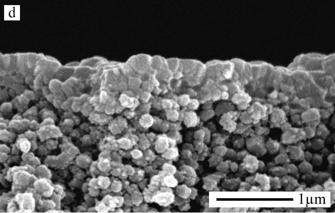
85 Figure 2. SEM surface images of the membranes A1(a), E1 (b,) A30 (c) and E30( d). Figure 3. SEM side view images of the membranes A1 (a), E1 (b), A30 (c) and E30 (d).
86 Figure 3 shows side views of samples A1, E1, A30 and E30. The film thickness for A1 and E1 is about 400 nm. The images also shows that the film on A30 (3c) is thinner than the film in the other membranes. The film thickness, measured with SEM, for all membranes prepared is shown in table 2. Table 2 shows results from the single gas permeation measurements, film thickness and ph in the aqueous solutions. All membranes prepared in the present work have higher single gas helium permeance than the ten reference membranes A3. This is probably due to slightly thinner films (c.f. Table 2) in the present work compared to the ten reference membranes. According to porosimetry data these membranes had similar quality as A3, showing that the lower permeance ratios is not an indication of defects. The high permeance will result in reduced permeance ratios due to increased relative pressure drop over the support, where Knudsen diffusion is the dominating transport mechanism [27]. Table 2. ph in the rinsing media, approximate film thickness measured with SEM and single gas permeation data for selected samples at room temperature. Pressure drop was 0.5 bar or in two cases 0.3 bar (indicated with *) and the permeate was at atmospheric pressure in all cases. No film thickness was possible to measure for sample S1 in accordance with the very high helium permeance. He permeance Permeance ratios Film thickness ph in aq. Sample (10-7 mol m -2 s -1 Pa -1 ) H 2 /He H 2 /SF 6 N 2 /He N 2 /SF 6 nm solution A3 87± E1 121± ± 50 - H1 106 ± ± 50 1 T1 104 ± ± W1 115 ± ± 50 7 A1 122 ± ± S1 322* E ± ± 50 - H ± ± 50 1 T ± ± W ± ± 50 7 A ± ± S30 319* The single gas data for samples exposed for 30 days supports the conclusions from porosimetry data. Samples E30 maintain similar helium permeance as the best membranes
87 exposed for 1 day and thus similar high quality and the helium permeance is increasing and the quality is decreasing in the order E30<H30<T30<W30<A30. The increased single gas permeance is accompanied by a decrease in the H 2 /He and N 2 /He ratios as expected due to higher relative pressure drop over the support [27]. This increase in permeance and decrease in permeance ratios could be explained both by the decrease in film thickness, as observed with SEM (c.f. Table 2 and discussion below) and the increase of pores > 1.1 nm as indicated by porosimetry data (c.f. Table 1). The observed reduction in film thickness by SEM, thus supports the hypothesis that the zeolite crystals are dissolved. The ph of each aqueous solution is shown in Table 2 and it implies a connection between ph and membrane quality. For the samples E30, H30, W30, A30, S30 the corresponding ph is (not defined), 1, 7, 11 and 13 and the helium permeances are 110, 128, 213, and 319. The results show a minimum dissolution at the low ph then an increase in dissolution with ph. The dissolution rate of silica also shows an increase with ph [14], but previous reports on zeolite dissolution shows minimum dissolution rate at neutral ph [28, 29]. These experiments were however performed on real aluminosilicates and at low ph, aluminium is preferentially dissolved [16, 29]. The discrepancy between the results obtained in this study and that in the literature regarding the presence of a minimum near ph 7 could be due to the difference in experimental procedures, with the current study performed using silicalite-1 films. The samples T30 are a special case, it is known that the TPA + ion has a stabilizing effect on the MFI structure [30, 31]. The (H 2, N 2 )/SF 6 ratios for membranes exposed for 30 days does not follow exactly the same trend observed by porosimetry and H 2 /He and N 2 /He single gas permeance ratios. This is explained by the fact that a large fraction of the SF 6 transport in the substrate occurs via Poiseuille flow, while all other molecules are transported via Knudsen diffusion [27]. As the permeance increases due to more pores > 1.1 nm and a thinner film, the relative pressure drop over the substrate will increase, and thus the total pressure in the substrate will increase, which will favor the SF 6 transport via Poiseuille flow. This explains why the (H 2, N 2 )/SF 6 ratios are almost constant for the samples H30, T30, W30 and A30, although both porosimetry and gas/helium ratios clearly show that the quality is varying for these samples, as discussed in [32]. Figure 4 shows XRD patterns for the same sample after 24h (A1) and 30 days (A30) of exposure to a 0.1 M ammonia solution. The integrated intensity of the silicalite-1 reflections is higher (6.74 cps*deg) for A1 than for A30 (5.76 cps*deg), which is accompanied by an opposite trend for reflection from the alumina support at 25.7 º 2. In concert with porosimetry, single gas permeation, and SEM results, the XRD data indicates that some of the
88 zeolite film has dissolved on samples A30, causing a reduction of zeolite reflections (less zeolite) and increased alumina reflection (less X-ray absorption of the zeolite film on top of the support) Intensity (linear scale) a Θ A1 A30 Intensity (linear scale) b A1 A Θ Θ Figure 4. XRD patterns on the same silicalite-1 membrane after storing in ammonia for 24h (A1) and 30 days (A30) in the 2 range º(a) and º (b). The width (FWHM) of the 501 reflection at 23.2º 2 for the silicalite-1 film was estimated after refinement and was 0.12 º 2 for A1 and 0.136º 2 for A30. The error RI between refined and experimental data was 4% for A1 and A30, indicating a good fit of the refined data. The FWHM of a quartz standard sample comprised of large crystals without defects, strain or stress was 0.07 º 2. In concert with all other data, the broader reflection for sample A30 compared to A1, indicates that the zeolite crystals are smaller in sample A30, likely caused by dissolution of zeolite due to the long exposure to the 0.1 M ammonia solution. The silicon content in the last 0.1 M ammonia solution used to expose samples A1 and A30 was 24.8 ppm and 0.6 ppm, respectively. The initially high content of silicon in the solution indicates that first synthesis residues and amorphous silica are dissolved. Once the synthesis residues are removed the ammonia will slowly dissolve the film as indicated by XRD and SEM. These finding leads us to the following hypothesis concerning the creations of micro- and mesopores in TPA-Silicalite-1 films due to exposure of aqueous solutions: It is most probable that the increased porosity is open grain boundaries, since the investigation was performed on TPA-silicalite-1 membranes. The rate of dissolution and hence the size and amount of extra pores, will depend on the ph of the solution, an increase in ph will lead to an increase in porosity. Depending on the texture of the grain boundaries, the
89 pores will be created differently. If there is non-zeolitic material, such as amorphous silica, inbetween the grains the pores will probably be created faster. If the crystal boundaries are intergrown the creation will be slower and relative to the decrease in film thickness.
90 Conclusions The present work has shown that the micro- and meso-porosity increased in thin silicalite- 1 membranes in a controlled way by long exposure to aqueous solutions at room temperature. This may be used intentionally to create pores in zeolite membranes but it also has effect on the lifetime of zeolite membranes in for example pervaporation applications. The porosity increases with the ph of the solution, from a very low increase at ph 1 to a complete dissolution of the film at ph 13. A short exposure to aqueous solutions has no effect on the porosity of the membrane, except for an exposure to 0.1M sodium hydroxide solution (ph 13), which will dissolve the film already after 24 hours. Short exposure to aqueous solutions such as ammonia and pure water will only dissolve synthesis residues and amorphous silica. This short exposure is therefore excellent to use on membranes after synthesis to remove residues without increasing then on-zeolitic porosity. Ethanol has no effect on the sililicate-1 membranes and could be considered as a storing media for zeolite membranes. Acknowledgement The authors acknowledge the Swedish Research Council (VR) for financially supporting this work.
91 References [1] J. Hedlund, J. Sterte, M. Anthonis, A.-J. Bons, B. Carstensen, N. Corcoran, D. Cox, H. Deckman, W. De Gijnst, and P.-P. de Moor, Microporous Mesoporous Mater., Highflux MFI membranes, 52 (2002) 179. [2] Z. Lai, G. Bonilla, I. Diaz, J.G. Nery, K. Sujaoti, M.A. Amat, E. Kokkoli, O. Terasaki, R.W. Thompson, M. Tsapatsis, and D.G. Vlachos, Science, Microstructural Optimization of a Zeolite Membrane for Organic Vapor Separation, 300 (2003) 456. [3] J. Hedlund, J. Porous Mat., Control of the Preferred Orientation in MFI Films Synthesized by Seeding, 7 (2000) 455. [4] J. Hedlund, S. Mintova, and J. Sterte, Microporous Mesoporous Mater., Controlling the preferred orientation in silicalite-1 films synthesized by seeding, 28 (1999) 185. [5] C. Andersson, J. Hedlund, F. Jareman, and J. Sterte, Silicalite-1 membranes with small crystal size, in: 14 th International Zeolite Conference, Cape Town, South Africa, 2004 [6] G. Bonilla, M. Tsapatsis, D.G. Vlachos, and G. Xomeritakis, J. Membr. Sci., Fluorescence confocal optical microscopy imaging of the grain boundary structure of zeolite MFI membranes made by secondary (seeded) growth, 182 (2001) 103. [7] G. Bonilla, D.G. Vlachos, and M. Tsapatsis, Microporous Mesoporous Mater., Simulations and experiments on the growth and microstructure of zeolite MFI films and membranes made by secondary growth, 42 (2001) 191. [8] F. Jareman, C. Andersson, and J. Hedlund, Microporous Mesoporous Mater., The influence of the calcination rate on silicalite-1 membranes, 79 (2005) 1. [9] J. Hedlund, F. Jareman, A.-J. Bons, and M. Anthonis, J. Membr.Sci, A masking technique for high quality MFI membranes, 222 (2003) 163. [10] J. Hedlund and F. Jareman, Curr. Opin. Colloid Interface Sci., Texture of MFI films grown from seeds, 10 (2005) 226. [11] M.J. den Exter, H. van Bekkum, C.J.M. Rijn, F. Kapteijn, J.A. Moulijn, H. Schellevis, and C.I.N. Beenakker, Zeolites, Stability of Oriented Silicalite-1 Films in View of Zeolite Membrane Preparation, 19 (1997) 13. [12] J. Dong, Y.S. Lin, M.Z.C. Hu, R.A. Peascoe, and E.A. Payzant, Microporous Mesoporous Mater., Template-removal-associated microstructural development of porous-ceramic-supported MFI zeolite membranes, 34 (2000) 241.
92 [13] E.R. Geus, J.C. Jansen, and H. van Bekkum, Zeolites, Calcination of large MFI-type single crystals: Part 1. Evidence for the occurrence of consecutive growth forms and possible diffusion barriers arising thereof, 14 (1994) 82. [14] R.K. Iler, The Chemistry of Silica: Solubility, Polymerisation, Colloidal and Surface Properties, and Biochemistry, Wiley, New York, [15] R.L. Hartman and H.S. Fogler, Ind. Eng. Chem. Res., Reaction kinetics and mechanisms of zeolite dissolution in hydrochloric acid, 44 (2005) [16] P.J. Kooyman, P. van der Waal, and H. van Bekkum, Zeolites, Acid dealumination of ZSM-5, 18 (1997) 50. [17] J.C. Groen, J.A. Moulijn, and J. Perez-Ramirez, J. Mater. Chem., Desilication: On the controlled generation of mesoporosity in MFI zeolites, 16 (2006) [18] J.C. Groen, L.A.A. Peffer, J.A. Moulijn, and J. Perez-Ramirez, Microporous Mesoporous Mater., On the introduction of intracrystalline mesoporosity in zeolites upon desilication in alkaline medium, 69 (2004) 29. [19] A. Cizmek, L. Komunjer, B. Subotic, M. Siroki, and S. Roncevic, Zeolites, Kinetics of zeolite dissolution: Part 1. Dissolution of zeolite A in hot sodium hydroxide, 11 (1991) 258. [20] A. Cizmek, L. Komunjer, B. Subotic, M. Siroki, and S. Roncevic, Zeolites, Kinetics of zeolite dissolution. Part 2. Dissolution of zeolite X in hot sodium hydroxide solutions, 11 (1991) 810. [21] Z. Lai, M. Tsapatsis, and J.P. Nicolich, Adv. Funct. Mater., Siliceous ZSM-5 membranes by secondary growth of b-oriented seed layers, 14 (2004) 716. [22] A. Navajas, R. Mallada, C. Tellez, J. Coronas, M. Menendez, and J. Santamaria, J. Membr. Sci., The use of post-synthetic treatments to improve the pervaporation performance of mordenite membranes, 270 (2006) 32. [23] T.C. Bowen, R.D. Noble, and J.L. Falconer, J. Membr. Sci., Fundamentals and applications of pervaporation through zeolite membranes, 245 (2004) 1. [24] H.W. Deckman, D.M. Cox, A.-J. Bons, B. Carstensen, R.R. Chance, E.W. Corcoran, W. De Gijnst, J.A. McHenry, J.J. Reinoso, R.B. Saunders, and P.J. Tindell, Characterization of zeolite membrane quality and structure, in: IWZMM2001 Book of Abstracts, 2001 [25] F. Jareman, J. Hedlund, D. Creaser, and J. Sterte, J. Membr. Sci., Modelling of single gas permeation in real MFI membranes, 236 (2004) 81.
93 [26] S.U. Rege and R.T. Yang, AIChE Journal, Corrected Horvath-Kawazoe equations for pore-size distribution, 46 (2000) 734. [27] F. Jareman and J. Hedlund, Microporous Mesoporous Mater., Single gas permeance ratios in MFI membranes: Effects of material properties and experimental conditions, 82 (2005) 201. [28] J. Cama, C. Ayora, X. Querol, and J. Ganor, Environ. Sci. Technol., Dissolution kinetics of synthetic zeolite NaP1 and its implication to zeolite treatment of contaminated waters, 39 (2005) [29] K.V. Ragnarsdottir, Geochim. Cosmochim. Acta, Dissolution kinetics of heulandite at ph 2-12 and 25 ºC, 57 (1993) [30] L.-Y. Hou and R.W. Thompson, Zeolites, Stability and growth of silicalite seeds: an observation of initial breeding, 9 (1989) 526. [31] M. Otake, Zeolites, MFI zeolite crystallization under controlled dosage of TPA template, 14 (1994) 42. [32] F. Jareman and J. Hedlund, Microporous Mesoporous Mater., Permeation of H2, N2, He and SF6 in real MFI membranes, 83 (2005) 326.
94
95 Paper III Water/hydrogen/hexane multicomponent selectivity of thin MFI membranes with different Si/Al ratio, Seyed Alireza Sadat Rezai, Jonas Lindmark, Charlotte Andersson, Fredrik Jareman, Klaus Möller and Jonas Hedlund, Microporous and Mesoporous Materials, In press
96
97 ARTICLE IN PRESS Microporous and Mesoporous Materials xxx (2007) xxx xxx Water/hydrogen/hexane multicomponent selectivity of thin MFI membranes with different Si/Al ratios Seyed Alireza Sadat Rezai a,1, Jonas Lindmark a, Charlotte Andersson a, Fredrik Jareman a, Klaus Möller b, *, Jonas Hedlund a, * a Division of Chemical Technology, Luleå University of Technology, SE Luleå, Sweden b Catalysis Research Group, University of Cape Town, Private Bag, Rondebosch 7701, South Africa Received 29 September 2006; received in revised form 19 March 2007; accepted 3 April 2007 Abstract MFI films with a thickness of about 550 nm were prepared on a-alumina substrates. The surface Si/Al ratios (XPS) were 157 and 62 for silicalite-1 and ZSM-5 films, respectively, and in accordance, XRD data indicated lower ratios for ZSM-5 films. Higher ratios were observed by ICP-AES for crystals grown in the bulk of the synthesis mixtures. Six membranes of each type were prepared. Porosimetry measurements showed that all membranes were of high and similar quality. Single gas permeances for H 2,N 2, He, CO 2 and SF 6 at 25 C were very similar within each type of membranes. However, the average hydrogen permeance was 27% lower and the average H 2 /SF 6 single gas permeance ratio was 67% higher for ZSM-5 membranes. These differences are attributed to a narrower effective pore diameter for the ZSM-5 membranes due to the sodium counter ions. Separation of mixtures of H 2 O, H 2 and n-hexane (helium balance) was investigated in the temperature range C. The highest separation factors a-h 2 O/H 2 were observed at 25 C and were 14.3 and 19.7 for silicalite-1 and ZSM-5, respectively. The membranes were selective also at 100 C and the separation factors were about 3.2 and 6 for silicalite-1 and ZSM-5, respectively. However, the selectivity decreased at elevated temperatures and the separation factor approached 1 at temperatures above 180 C for both membrane types. The observed water selectivity was attributed to weak adsorption of water on polar sites. A low (1.5 3) a-h 2 O/n-C 6 separation factor was observed for both membrane types for the entire investigated temperature range. Ó 2007 Elsevier Inc. All rights reserved. Keywords: MFI zeolite membranes; Water; Hydrogen; Selectivity; Multicomponent permeance 1. Introduction Molecular sieve films with well-defined pores may be used for a variety of purposes such as for membrane applications [1,2], optical sensors [3 5] and electronic functions [6]. Zeolite membranes are particularly interesting for separation as they can withstand the harsh thermal and chemical conditions of many industrial processes [7] where other (organic) membranes are often found shortcoming due to * Corresponding authors. address: Jonas.Hedlund@ltu.se (J. Hedlund). 1 Visiting researcher, Catalysis Research Centre, University of Cape Town. their limited temperature stability. The microstructure of zeolites allows for separation of mixtures with small and similar molecular diameters. Synthesis, characterization and separation performance of various zeolite membranes have been studied including silicalite-1 [8 11], ZSM-5 [12 15], zeolite A [16] and zeolite Y [17,18]. MFI type membranes have gained particular interest in separation due to similar pore diameter of these zeolites to the critical diameter of many industrially important molecules. Separation by zeolite membranes is due to molecular sieving and/or preferential adsorption and/or diffusion effects [19]. The transport in the membranes may be governed by the dominance of either of the mechanisms or a combination. The separation selectivity in zeolite /$ - see front matter Ó 2007 Elsevier Inc. All rights reserved. doi: /j.micromeso
98 ARTICLE IN PRESS 2 S.A.S. Rezai et al. / Microporous and Mesoporous Materials xxx (2007) xxx xxx membranes varies significantly with the structure, crystal orientation, film thickness, Si/Al ratio, adsorption effects, composition and kinetic diameter of the permeating species [19]. By changing the Si/Al ratio in the zeolite the polarity of a membrane can be adjusted. A more hydrophilic membrane would adsorb polar molecules more strongly and block the pores for transport of other species as a result of the stronger adsorption. Zeolite A membranes have been applied in large-scale pervaporation plants for solvent dehydration [2]. However, these zeolite films are often as thick as 30 lm hence show a high mass transfer resistance. Besides dehydration processes, many currently relevant reactions take place in the presence of water, e.g. the Fischer Tropsch (FT) synthesis: yielding hydrocarbons and water from H 2 and CO, or steam reforming of hydrocarbons for H 2 production. It has been reported that water may deactivate the FT catalyst [20,21], hence selective removal of water may benefit the FT synthesis, whereas selective removal of H 2 would improve equilibrium for steam reforming. Although water vapor may be present in small amounts in many potential streams for membrane applications, its effect on the separation efficiency has gained little attention [15,22]. Furthermore, if a thin zeolite membrane is prepared, the permeance of gases through the membrane will be high [23] reducing the required membrane area to process a certain stream. In the present work, 550 nm MFI membranes with different Si/Al ratios were explored for separation of water/ hydrogen mixtures in the presence of hydrocarbons. All parameters such as film thickness, preferred orientation and conditions during testing were kept constant in order to evaluate the effect of the Si/Al ratio in the film on the separation. 2. Experimental 2.1. Membrane fabrication Commercial asymmetric a-alumina microfiltration filters (Inocermic GmbH) with a disk diameter of 25 mm were used as supports. The average pore size was 100 nm in the 30 lm thick top-layer and 3 lm in the 3 mm thick bottom layer. The supports were masked and seeded as described previously [23]. TPA-silicalite-1 seeds with an average crystal size of 60 nm were used for seeding of the masked supports. The seeds were prepared from a synthesis solution with the molar composition 9 TPAOH:25 SiO 2 :360 H 2 O:100 EtOH. Seeding of the supports was performed in a glass beaker. Each support was placed horizontally with the top surface upwards on the bottom of the beaker. The level of the seed suspension was approximately 1 mm over the support surface and the ratio between membrane area and volume of seeding solution was approximately 150 m 1. After seeding, the supports were immediately immersed in a synthesis solution with a molar composition of 3 TPAOH:25 SiO 2 :1450 H 2 O:100 EtOH for silicalite-1 films and 3 TPAOH:0.25 Al 2 O 3 :Na 2 O:25 SiO 2 :1600 H 2 O:100 EtOH for ZSM-5 films. Hence the Si/ Al ratios for silicalite-1 and ZSM-5 synthesis solutions were infinite and 50, respectively. The Na/Al ratio is 4 in the ZSM-5 synthesis mixture. Film synthesis was carried out in a polyethylene tube under reflux. The tube was heated by an oil bath kept at 100 C and the surface of each support was directed almost vertically but slightly tilted downwards to avoid any sedimentation or attachment of gas bubbles from the boiling synthesis solution on the surface of the film. The ratio between membrane area and volume of synthesis solution was approximately 15 m 1. However, the seeding and synthesis geometries have been varied during the years within a range and no effect on film quality has been observed. For the sake of simplicity, films grown in a silicalite-1 synthesis mixture were denoted silicalite-1 and films grown in a ZSM-5 synthesis solution were denoted ZSM-5. The silicalite-1 membranes were grown by hydrothermal treatment for 36 h and the ZSM- 5 membranes for 27 h in order to obtain similar film thicknesses. Six replicates of each membrane type were fabricated and labelled Sx or Zx, where S and Z denote silicalite-1 and ZSM-5, respectively. The letter x in the label is the sample number from 1 to 6. After hydrothermal treatment the membranes were cooled in the synthesis solution and rinsed with a 0.1 M NH 3 solution for 24 h. Since each support was masked [23], the interior of each support was completely filled with polyethylene wax and the top surface was accessible for seeding. Therefore, no zeolite will grow inside and only a small amount of zeolite may grow on the back and lateral sides, while a dense zeolite film may for on top of each support. After film growth, the membranes were calcined at 500 C for 6 h with a heating rate of 0.2 C/min and a cooling rate of 0.3 C/min, in order to remove template molecules, cationic polymer molecules used for seeding and hydrocarbon wax used for masking Physical characterisation A Philips XL30 scanning electron microscope equipped with a LaB 6 emission source running at 30 kv was used to study film thickness and morphology of the membranes. The samples were coated with a thin gold film by sputtering prior to investigation. X-ray diffraction (XRD) data were recorded using a Siemens D5000 diffractometer. Samples were investigated in the two-theta range 5 50 in Bragg Brentano geometry. Two-theta scans in the range were also performed with grazing incidence angle (1.0 ) and thin film accessories, i.e. a long Soller slit and a LiF monochromator was used in this case. The latter data was used to determine the positions of the two MFI peaks at approximately 45.0 and 45.5, 2h in an attempt to estimate the Si/Al ratio of the MFI film as described by Bibby et al. [24] for MFI powder. Elemental analysis of the film surface was carried out by X-ray photoelectron spectroscopy (XPS) using a KRATOS Axis Ultra electron

99 ARTICLE IN PRESS S.A.S. Rezai et al. / Microporous and Mesoporous Materials xxx (2007) xxx xxx 3 spectrometer. ICP-AES measurements of the elemental composition of the zeolite crystals that formed in the bulk of the synthesis mixture during film growth were performed Permeation measurements n-hexane (n-c 6 ) porosimetry was used to estimate the quality of the prepared membranes. The porosimetry experiment is described in detail elsewhere [23,25]. It has been shown that porosimetry can be used to estimate the amount and size distribution of defects in zeolite membranes and that this method is more informative than single gas permeation measurements [26 28]. Single gas permeation measurements of H 2,N 2, He, SF 6 and CO 2 were carried out directly after the calcination procedure. The membranes were mounted in a stainless steel cell. Rubber gaskets were used for measurements at room temperature and graphite gaskets were used above room temperature. An absolute pressure difference of 1 bar was applied, and the flow through the membrane was measured using a flowmeter (ADM 1000, J&W Scientific). No sweep gas was used during single gas measurements. Separation experiments were performed using a Wicke- Kallenbach apparatus. The membranes were mounted in a stainless steel cell and sealed with graphite gaskets. Hydrogen and helium were fed by three mass flow controllers to saturators kept at 20 C by a thermostat bath. 500 ml/min of helium were fed to a water saturator, 50 ml/min of helium were fed to a n-c 6 saturator and 400 ml/min of hydrogen were fed to a water saturator. The feed composition for the separation measurements was thus 42 kpa hydrogen, 2.1 kpa water, 0.71 kpa n-c 6 and helium balance to a total of kpa at a flowrate of 977 ml/min (STP). Helium at 200 ml/min (STP) was used as sweep gas with a pressure of kpa. This feed composition was selected to approach a Fischer Tropsch reaction mixture, while keeping the system as simple as possible. A thermocouple (type K) was connected to the membrane cell in order to record the temperature at the membrane. A Varian 3800 GC equipped with a capillary column and two packed columns (molecular sieve and chromosorb) was connected online. Thermal conductivity and flame ionisation detectors connected in series were used for quantitative analysis of the gas compositions. Helium was used as the carrier gas. Membranes were reactivated in situ at 400 C in flowing helium for 8 h at the end of each permeation measurement. The separation factor was calculated as follows: a i;j ¼ x i=x j permeate ð1þ x i =x j feed with x i = mole fraction of species i. It should be noted that the fraction of any component in the feed crossing the membrane remained below 11% even at the highest temperatures in this work. This is important, since the composition on the feed side of the membrane then can be approximated with the feed composition when calculating the permeance and separation factors (Eq. (1)). 3. Results and discussion 3.1. Physical characterization Fig. 1a and b show side view images and Fig. 1c and d show surface images of silicalite-1 and ZSM-5 films, respec- Fig. 1. Side view images, (a) and (b), and surface images, (c) and (d), of silicalite-1 and ZSM-5 films, respectively.
100 ARTICLE IN PRESS 4 S.A.S. Rezai et al. / Microporous and Mesoporous Materials xxx (2007) xxx xxx tively. The film thickness was about 550 nm for both the silicalite-1 and ZSM-5 films. Both films appeared dense. Fig. 2 shows XRD diffractograms of a silicalite-1 and a ZSM-5 membrane in the two-theta interval The very strong peaks at about 25.6, 35.1, 37.8 and 43.4, 2h emanate from the alumina support. The remaining peaks are typical for weakly a-oriented MFI films grown by this procedure and similar results have been reported before [23]. Table 1 shows the integrated intensity of the MFI peak at h. The intensity has been normalized using the very strong alumina peak at 25.6, 2h as internal standard. The integrated intensity of this MFI peak is 7.6 ± 0.2 for silicalite-1 and 7.5 ± 0.3 for ZSM-5, indicating an almost constant zeolite amount for all samples in accordance with SEM observations. The exact position of the two MFI peaks at approximately 45.0 and 45.5, 2h were determined in an attempt to estimate the Si/Al ratio of the MFI film as described by Bibby et al. [24] for MFI powder. They showed that the difference in angle, D( 2h), between the two peaks is inversely proportional to the aluminum content in MFI powder. For the MFI films prepared in the present work, D(2h) was ± 0.01 (average and 95% confidence interval for four samples) and ± 0.01 for silicalite-1 and ZSM-5, respectively. It is possible that a calibration curve for zeolite powder is not applicable for determination of the aluminum content in zeolite films, due to strain in films amongst other factors. However, since a larger D(2h) was Fig. 2. XRD diffractograms of a silicalite-1 and a ZSM-5 membrane in the 2h range Table 1 Integrated intensities of the MFI peak at 22.9,2h for three silicalite-1 and three ZSM-5 membranes Membrane Integrated intensity (countsæ ) S4 7.5 S5 7.8 S6 7.4 Average silicalite ± 0.2 Z3 7.6 Z4 7.1 Z6 7.7 Average ZSM ± 0.3 The intensity of the MFI peak has been normalized using the alumina peak at 25.6, 2h as internal standard. observed for silicalite-1, this indicates a higher Si/Al ratio for this sample. In order to appreciate the composition of the zeolite better, in particular the Si/Al ratio, additional characterization of the membrane surface with XPS and of the crystals formed in the bulk of the synthesis mixture with ICP-AES was carried out. In accordance with the XRD observations, XPS showed that the Si/Al ratio on the membrane surface was 157 for silicalite-1 and 62.4 for ZSM-5. These ratios should be compared with the ratios in the synthesis mixtures, which were infinite and 50, for silicalite-1 and ZSM-5, respectively. It is likely that some aluminum leached from the support and was incorporated in the zeolite during film growth, which may explain the low Si/Al ratio observed by XPS for the silicalite-1 membrane surface. Furthermore, some of the aluminum detected on the surface by XPS may be non-framework aluminum, not affecting the crystal structure for silicalite-1 and ZSM-5. A higher aluminum concentration in the ZSM-5 system was also supported by the ICP-AES results for the zeolite crystals that formed in the bulk of the synthesis mixture during growth of the zeolite membranes. The observed Si/Al ratios were >1441 (Al below the detection limit) for silicalite-1 bulk crystals and 383 for ZSM-5 bulk crystals. The Si/Na ratios in these crystals were >625 (Na below the detection limit) and 59 for silicalite-1 and ZSM-5, respectively. The ZSM-5 crystals were thus in the sodium form (NaZSM-5), as expected from a synthesis mixture with a Na/Al ratio of 4. It should be noted that the bulk composition of the zeolite crystals that formed in the bulk of the synthesis mixture may differ significantly from the bulk composition of the film in the zeolite membrane due to at least two reasons: As stated above, aluminum may be incorporated in the growing zeolite film due to leaching of the support and the film is grown from seeds, while the crystals that form in the bulk of the synthesis solution grow from nuclei. However, all analyses of the elemental composition of the samples show more aluminum in the ZSM-5 system Permeation measurements All membranes were first evaluated by single gas experiments (cf. Table 2). It should be noted that single gas permeance ratios are a function of membrane quality, film thickness, morphology, test conditions [27] and chemical composition, i.e. Si/Al ratio. However, in the present work, membrane quality, film thickness, morphology and test conditions were kept constant. Almost constant permeances were obtained within each group of membranes, which indicate that the quality of these membranes is similar. The silicalite-1 membranes show on average 43% higher He permeance and 37% higher H 2 permeance, which may be attributed to steric constraints of the counter ions and hence reduced effective pore diameter in ZSM-5. Since the permeance of these molecules appear to be influenced
101 ARTICLE IN PRESS S.A.S. Rezai et al. / Microporous and Mesoporous Materials xxx (2007) xxx xxx 5 Table 2 Hydrogen permeance/( mol/m 2 s Pa) and single gas perm-selectivity experiments at room temperature (25 ± 2 C) for 6 silicalite-1 (S1 S6) and 6 ZSM-5 membranes (Z1 Z6), with a DP of 1 bar Membrane H 2 He H 2 /N 2 H 2 /He H 2 /SF 6 H 2 /CO 2 S S S S S S Average ± ± ± ± ± ± 0.19 Z Z Z Z Z Z Average ± ± ± ± ± ± 0.03 Averages are given with standard deviations. CO 2 permeance was not measured on all membranes. by pore size and the observed average H 2 /He permeance ratio is for both membrane types, which is significantly above the Knudsen ratio of 1.4, these results indicate that the transport of these molecules may involve both Knudsen like diffusion and surface (configurational) diffusion. This hypothesis is supported by work reported by Xiao and Wei [27]. In their hypothesis, H 2 and He are probably transported by Knudsen diffusion in ZSM-5, but the system is a borderline case to configurational diffusion. The average permeance ratio of H 2 /He for the two membrane types differ by as little as about 3%, indicating that these molecules are not influenced by polarisation and/or adsorption effects due to different chemical composition of the membrane types. In contrast, the average H 2 /N 2 and H 2 /CO 2 permeance ratios differ more for the two membrane types and are 15 30% lower for the ZSM-5 membranes. The lower H 2 /N 2 and H 2 /CO 2 permeance ratios observed for ZSM-5 is caused by enhanced transport of N 2 and CO 2 due to their larger quadrupolar moment, probably by enhanced surface diffusion in addition to Knudsen like diffusion. The average H 2 /SF 6 permeance ratio is 67% higher for the ZSM-5 membranes, as a result of a much larger reduction of SF 6 permeance compared to H 2 for ZSM-5. The size of the SF 6 molecule is closer to the critical diameter of the NaZSM-5 pores compared to the H 2 molecule, which maybe explains why the SF 6 permeance is reduced more than the H 2 permeance in NaZSM-5. Fig. 3 illustrates n-c 6 porosimetry data for three silicalite- 1 (a) and three ZSM-5 (b) membranes. As was also indicated by single gas data, all these membranes have high and similar quality since the He permeance drops about 99% when the relative partial pressure of n-c 6 is increased from 0 to A relative pressure of 0.01 of n-c 6 blocks the zeolite pores and the remaining flow permeates via pores (defects) larger than the zeolite pores [23,25,26]. In accordance with the single gas experiments, a difference in helium permeance Fig. 3. Helium permeance as a function of partial pressure of n-hexane measured at 25 C for silicalite-1 (a) and ZSM-5 membranes (b). at relative pressure of 0 is observed for the two membrane types. The helium permeance for silicalite-1 is ± mol 1 m 2 Pa 1, whereas the permeance for ZSM-5 is ± mol 1 m 2 Pa 1 (average and standard deviation for three samples). These helium permeances are slightly smaller than what was observed in the single gas experiments, which may be caused by some coke deposition during the separation measurements. The porosimetry measurements were carried out after separation measurements.
102 ARTICLE IN PRESS 6 S.A.S. Rezai et al. / Microporous and Mesoporous Materials xxx (2007) xxx xxx 3.3. Separation experiments Fig. 4 shows separation factors and permeances for two membranes of each type. The data are similar for each membrane type, indicating excellent reproducibility in membrane preparation and testing. Fig. 4a shows the H 2 O/H 2 and H 2 O/n-C 6 separation factors for membranes S5 and S6 as a function of temperature. At 25 C, the average separation factor a-h 2 O/H 2 was The membranes were selective also at 100 C and the average separation factor was 3.2. This high separation factor is attributed to adsorption of water on polar sites, especially at low temperature. The separation factor approach 0.75 at temperatures above 150 C. The separation factor a-h 2 O/n-C 6 increases from 1.5 to 3 within the investigated temperature range. Fig. 4b shows the H 2 O/H 2 and H 2 O/n-C 6 separation factors for membranes Z4 and Z5 as a function of temperature. A similar trend for the H 2 O/H 2 separation factor is observed for these membranes, but the separation factors are higher (2 times at 100 C) at temperatures below 180 C, which is attributed to stronger polarity in ZSM-5. Similarly, the a-h 2 O/n-C 6 separation factor is increasing with temperature from 1.5 to 2.2 between 25 and 400 C. Fig. 4c and d shows the permeances as a function of temperature. The hydrogen permeance increases two orders of magnitude with increasing temperature. At low temperatures, the pores are probably blocked by water and/or n-c 6 as in the porosimetry experiment. Silicalite-1 and ZSM-5 with high Si/Al should adsorb hydrocarbons in favor of water and it is thus likely that n-c 6 is responsible for more pore blocking than water although the concentration was three times lower. These molecules are desorbed at least partially at higher temperatures, allowing hydrogen to permeate. The hydrogen permeance at 350 C is approximately mol 1 m 2 Pa 1 for silicalite-1 and mol 1 m 2 Pa 1 for ZSM-5. This is about a factor 3.4 times lower than observed in the single gas measurements at 25 C, which may be caused by reduced adsorption (and surface diffusion) due to higher temperature, competitive adsorption (of water, helium or n-c 6 )or back diffusion of helium from sweep to feed side. The permeances of water and n-c 6 are less dependent on temperature, the permeance of water increased by less than a factor of 3, while that of n-c 6 increased by less than 50% over the same temperature range, possibly due to counteracting adsorption and diffusion effects. The rapid decrease for the a-h 2 O/H 2 separation factor for both membrane types is a result of rapid increase of H 2 permeance with increasing temperature. Also the higher a-h 2 O/H 2 separation factor in ZSM-5 is due to the lower H 2 permeance in the ZSM-5 membranes (pores more blocked by water) compared to that for the silicalite-1 membranes. The variation of the water and n-c 6 permeance with membrane type has a minor impact on the a- H 2 O/H 2 separation factor. The presence of cations in ZSM-5 is expected to favor the adsorption and permeance of water [29]. However, Fig. 4. Ternary H 2 O/H 2 /n-c 6 permeance (a), (b) and selectivity (c) and (d) for silicalite-1 and ZSM-5 membrane. Feed water vapor partial pressure is 2.1 kpa, n-hexane vapor partial pressure 0.71 kpa, and H 2 partial pressure is 42 kpa, with He balance to a total of kpa. Sweep gas; He at 200 ml/min and kpa.
103 ARTICLE IN PRESS S.A.S. Rezai et al. / Microporous and Mesoporous Materials xxx (2007) xxx xxx 7 the results show that the water permeance and the H 2 O/n- C 6 separation factor are lower in ZSM-5 at high temperatures while at low temperatures no difference is observed between the two membrane types. This illustrates the complexity of the interactions during multicomponent separations and without knowledge of multicomponent adsorption isotherms it is difficult to explain this behavior. In the absence of n-c 6, the permeances at 25 C were about 5 and 6 times higher for H 2 OandH 2, respectively, than in the presence of n-c 6. The a-h 2 O/H 2 separation factor was about 40% and 55% lower for silicalite-1 and ZSM- 5 membranes, respectively. The a-h 2 O/H 2 separation factor decreased and the permeances increased with increasing temperature similarly to the measurements with n-c 6 in the feed. In agreement with the previous discussion n-c 6 appears to have a strong pore blocking effect, reducing the permeances of both H 2 OandH 2 but the permeance of H 2 is reduced more, resulting in a higher a-h 2 O/H 2 separation factor in the presence of n-c Conclusions Twelve MFI membranes with different Si/Al ratios were successfully grown on asymmetric a-alumina micro-filtration filters. The film thickness was about 550 nm for all membranes according to SEM and XRD data indicated a constant zeolite amount on all membranes. Porosimetry results showed that the quality of all membranes was high. The single gas permeance data was consistent with the porosimetry data. The chemical composition of the membranes has a significant effect on single gas permeances and permeance ratios as well as separation factors and permeances in multi component separation experiments for the water/hydrogen/n-hexane system. The addition of aluminum results in increased selectivity at low temperatures, however, above 180 C this effect is no longer observed. Acknowledgements The authors acknowledge STEM (Swedish Energy Agency), NRF (South African National Research Foundation) and SIDA (Swedish Agency for International Development Cooperation) for financially supporting this work. References [1] E. Piera, C.A.M. Brenninkmeijer, J. Santamaria, J. Coronas, J. Membr. Sci. 201 (1 2) (2002) 229. [2] Y. Morigami, M. Kondo, J. Abe, H. Kita, K. Okamoto, Separ. Purif. Tech. 25 (2001) 251. [3] J. Zhang, J. Dong, M. Luo, H. Xiao, S. Murad, R.A. Normann, Langmuir 21 (19) (2005) [4] D.P. Mann, T. Paraskeva, K.F.E. Pratt, I.P. Parkin, D.E. Williams, Meas. Sci. Tech. 16 (5) (2005) [5] M. Grahn, Z. Wang, M. Lidstrom-Larsson, A. Holmgren, J. Hedlund, J. Sterte, Micropor. Mesopor. Mater. 81 (1 3) (2005) 357. [6] A. Mitra, T.G. Cao, H.T. Wang, Z.B. Wang, L. Huang, S. Li, Z.J. Li, Y.S. Yan, Ind. Eng. Chem. Res. 43 (12) (2004) [7] J. Caro, M. Noack, P. Koelsch, R. Schaefer, Micropor. Mesopor. Mater. 38 (1) (2000) 3. [8] E. Mateo, R. Lahoz, G.F. De La Fuente, A. Paniagua, J. Coronas, J. Santamaria, Chem. Mater. 16 (24) (2004) [9] J. Hedlund, F. Jareman, A.-J. Bons, M. Anthonis, J. Membr. Sci. 222 (1 2) (2003) 163. [10] C.J. Gump, X. Lin, J.L. Falconer, R.D. Noble, J. Membr. Sci. 173 (1) (2000) 35. [11] W.J.W. Bakker, F. Kapteijn, J. Poppe, J.A. Moulijn, J. Membr. Sci. 117 (1 2) (1996) 57. [12] S. Gopalakrishnan, T. Yamaguchi, S.-I. Nakao, J. Membr. Sci. 274 (1 2) (2006) 102. [13] J.L. Falconer, M. Arruebo, R.D. Noble, J. Membr. Sci. 269 (1 2) (2006) 171. [14] Z. Lai, G. Bonilla, I. Diaz, J.G. Nery, K. Sujaoti, M.A. Amat, E. Kokkoli, O. Terasaki, R.W. Thompson, M. Tsapatsis, D.G. Vlachos, Science 300 (5618) (2003) 456. [15] J. Hedlund, M. Noack, P. Kolsch, D. Creaser, J. Caro, J. Sterte, J. Membr. Sci. 159 (1 2) (1999) 263. [16] M.A. Salomon, J. Coronas, M. Menendez, J. Santamaria, Appl. Catal. Gen. 200 (1) (2000) 201. [17] M. Lassinantti, J. Hedlund, J. Sterte, Microporous. Mesoporous. Mater. 38 (1) (2000) 25. [18] H. Kita, T. Inoue, H. Asamura, A. Murata, K. Tanaka, K. Okamoto, Chem. Comm. (1997) [19] S. Nair, M. Tsapatsis, in: S.M. Auerbach, K.A. Carrado, P.K. Dutta (Eds.), Handbook of Zeolite Science and Technology, Marcel Dekker Inc., New York, 2003, pp [20] M.P. Rohde, D. Unruh, G. Schaub, Membrane application in Fischer Tropsch synthesis reactors overview of concepts, in: International Conference on Gas Fuel 05, Elsevier, Amsterdam, 1000 AE, Netherlands, [21] M.P. Rohde, D. Unruh, G. Schaub, Indu. Eng. Chem. Res. 44 (25) (2005) [22] O. Pachtova, I. Kumakiri, M. Kocirik, S. Miachon, J.-A. Dalmon, J. Membr. Sci. 226 (1 2) (2003) 101. [23] J. Hedlund, J. Sterte, M. Anthonis, A.-J. Bons, B. Carstensen, N. Corcoran, D. Cox, H. Deckman, W. De Gijnst, P.-P. de Moor, F. Lai, J. McHenry, W. Mortier, J. Reinoso, J. Peters, Microporous. Mesoporous. Mater. 52 (3) (2002) 179. [24] D.M. Bibby, L.P. Aldridge, N.B. Milestone, J. Catal. (72) (1981) [25] H.W. Deckman, D.M. Cox, A. Bons, B. Carstensen, R. Chance, E.W. Corcoran, W.D. Gijnst, J. McHenry, J. Reinoso, R.B. Saunders, and P.J. Tindall, in: IWZMM2001, [26] F. Jareman, J. Hedlund, D. Creaser, J. Sterte, J. Membr. Sci. 236 (1 2) (2004) 81. [27] F. Jareman, J. Hedlund, Microporous. Mesoporous. Mater. 82 (1 2) (2005) 201. [28] J. Hedlund, F. Jareman, and C. Andersson, Factors affecting the performance of MFI membranes, in: 14th International Zeolite Conference, Cape Town, South Africa, [29] M.P. Bernal, E. Piera, J. Coronas, M. Menendez, J. Santamaria, Catal. Today 56 (2000)
104
105 Paper IV Crack formation in -alumina supported MFI zeolite membranes studied by in-situ High Temperature Synchrotron Powder Diffraction, Magdalena Lassinantti Gualtieri, Charlotte Andersson, Fredrik Jareman, Jonas Hedlund, Alessandro F. Gualtieri, Matteo Leoni and Carlo Meneghini, Journal of Membrane Science, Volume 290, Issues 1-2, 1 March 2007, Pages
106
107 Journal of Membrane Science 290 (2007) Crack formation in -alumina supported MFI zeolite membranes studied by in situ high temperature synchrotron powder diffraction Magdalena Lassinantti Gualtieri a,, Charlotte Andersson a, Fredrik Jareman a, Jonas Hedlund a, Alessandro F. Gualtieri b, Matteo Leoni c, Carlo Meneghini d a Department of Chemical Engineering and Geosciences, Luleå University of Technology, SE Luleå, Sweden b Dipartimento di Scienze della Terra, Università di Modena e Reggio Emilia, Via S. Eufemia 19, I Modena, Italy c Dipartimento di Ingegneria dei Materiali, Università di Trento, I Mesiano (TN), Italy d Dipartimento di Fisica E. Amaldi Università di Roma Tre, Via della Vasca Navale 84, I Roma, Italy Received 17 August 2006; received in revised form 1 December 2006; accepted 11 December 2006 Available online 16 December 2006 Abstract Cracks are frequently formed in -alumina supported MFI membranes during calcination. To better understand crack formation, in situ powder diffraction data were collected during calcination of a type of MFI membrane (ca nm thick) which is known to crack reproducibly. In addition, data for MFI powder and a blank support were also collected. Both a synchrotron radiation facility and an in-house instrument were used. The unit cell parameters were determined with the Rietveld method, and the strain in the direction perpendicular to the film surface was calculated for the film as well as for the support. The microstrain in the support was also estimated. Based on the results obtained here, a model for crack formation in this type of MFI membrane was proposed. The lack of cracks in other types of MFI membranes (ca. 500 nm) prepared in our laboratory is also explained by the model. In thicker MFI films, the crystals are well intergrown. During heating, the MFI crystals contract and the -alumina support expands. Consequently, a thermal stress develops in the composite which eventually leads to formation of cracks in the film and structural defects in the support. In thinner films, the crystals are less well intergrown and the thermal expansion mismatch leads to opening of grain boundaries rather than cracks Elsevier B.V. All rights reserved. Keywords: MFI zeolite membrane; In situ study; Synchrotron powder diffraction; Crack formation; Rietveld method 1. Introduction The potential industrial applications of polycrystalline zeolite membranes are not fully explored. This explains the increasing number of papers and patents on this specific topic. To this aim, MFI is a particularly interesting zeolite structure topology due to the pores with a size close to the kinetic diameter of many industrially important molecules. MFI zeolites with a high Si/Al ratio generally require the addition of organic template molecules for the synthesis. Frequently used organic templates are quaternary ammonium cations such as TPA + (tetrapropylammonium). The template molecules are trapped in the zeolite channels and are usually removed by calcination to activate the membrane. Corresponding author. Tel.: ; fax: address: mgualtieri@unimore.it (M. Lassinantti Gualtieri). For good separation performance, no alternative pathways in the form of defects such as open grain boundaries, pinholes and cracks should exist in the film [1 4]. Cracks are possibly the most troublesome type of defect and may form during calcination [1]. In an early work, crack formation during template removal of MFI single crystals (cube-shaped silicalite, fluoride-synthesized silicalite and vanadium-containing silicalite) was investigated [5]. In large crystals (>300 m average crystal size) some straight cracks along the c-axis developed at 260 C. The occurrence of straight cracks seems to be related to the dehydration of the framework during the initial Hofmann elimination reaction of TPA +. Random cracking was observed in cube-shaped crystals larger than 150 m (more severe in larger crystals). These observations match the temperature interval in which degradation of tripropylamine via -elimination reactions occurs. It was postulated that the development of random cracks was related to the formation of carbonaceous species within /$ see front matter 2006 Elsevier B.V. All rights reserved. doi: /j.memsci
108 96 M. Lassinantti Gualtieri et al. / Journal of Membrane Science 290 (2007) the zeolite framework. Pachtová et al.[6] studied the TPA removal in large silicalite-1 crystals of three different sizes. No cracks were observed in the smallest crystal (L c = 130 m) after calcination in air. In larger crystals, cracks developed in both air and nitrogen atmosphere. In the medium-sized crystals (L c = 190 m), cracks were found after complete template removal, whereas in the largest crystals (L c = 230 m) they already appeared after partial calcination. Hence, in concert with the results of Geus and van Bekkum [5], the formation of cracks was apparently dependent on the crystal size. It is well known that a thermal expansion mismatch between bonded materials may result in stress and consequently cracks in a composite. In fact, Geus and van Bekkum suggested that cracks in supported MFI membranes were due to thermal stress during calcination [5]. The MFI structure experiences a strong contraction during template removal, which occurs in the approximate temperature range C [5,7 9]. Instead, the -alumina supports used for MFI films expand during heating [8 10]. Furthermore, the unit cell of the calcined framework is smaller than the as-synthesized one [5,7,9,11]. The difference is due to the contraction of the b- and c-axes which is only partly compensated by an expansion of the a-axis in the calcined form [7,9,11]. den Exter et al. [12] studied b-oriented silicalite-1 films on dense silicon wafers. Derived from crystallographic data for as-synthesized and calcined silicalite-1, the authors reported that the change (%) in the unit cell dimensions after calcination (ex situ data) was 0.71, and for the a-, b- and c-axis, respectively. Based on these results and a quantitative estimation of the a- and b-oriented crystallites in the film, the calcined crystal layer would show an expansion with respect to the assynthesized film. In fact, a buckling of the calcined crystal layer was evident. The cracks observed in the film were attributed to compressive stress in the calcined layer. To better understand the crack formation process in MFI membranes, the thermal behavior of the porous support as well as that of the zeolite film must be investigated. An appropriate technique is high temperature X-ray powder diffraction (HT- XRPD) which allows to follow the d-spacings of the crystal planes as a function of temperature. Consequently, the strain in the sample can be followed as a function of temperature by comparing the d-spacings in the film with those in a non-stressed sample. Dong et al. [8] performed a HT-XRPD study of silicalite- 1 films on porous yttria-doped zirconia (YZ) supports as well as ZSM-5 films on porous -alumina supports. The films were composed of randomly oriented crystals. The MFI crystals formed in the bulk of the synthesis solution were also investigated. The films were defective after calcination. Open grain boundaries were present in the calcined ZSM-5 films whereas cracks were detected in the films of silicalite-1. Thermal expansion curves of the composites were determined during heating of the as-synthesized samples. It was shown that the MFI unit cell experiences a large contraction during template removal, while the support expands. During cooling, after template removal, the zeolite expands while the support contracts. In addition, the thermal expansion of the various samples was shown to be different. However, the strain in the films during the temperature ramp was not reported, possibly because the different Si/Al ratios in the samples masked the difference in unit cell dimension caused by strain in the film. Crack-resistant MFI membranes were recently studied by Jeong et al. [10]. The authors performed a HT-XRPD study (using synchrotron radiation (SR)) of an oriented MFI film with a thickness of about 10 m. The film was prepared on a thin mesoporous silica layer deposited on a porous -alumina support. They found that the crystals in the film experienced an in-plane compressive strain (i.e. in the direction parallel to the film surface) during the entire calcination procedure. It was speculated that this behavior possibly could explain the lack of cracks in this system. No HT-XRPD study of -alumina supported MFI films which crack during calcination had been reported. This recently prompted a preliminary HT-XRPD investigation of such a film [9]. In addition, MFI powder was also investigated. The Rietveld method was used to determine the unit cell parameters in the MFI film and the -alumina support as well as MFI powder in situ during the entire calcination procedure (i.e. both heating and cooling) [9]. The different thermal behavior of the film and the powder was attributed to tensile stress in the film during heating. The results of the preliminary investigation were however not sufficient to formulate a conclusive model for the crack formation process observed in the -alumina supported MFI films prepared in our laboratory [1,9]. The present work is a natural follow-up of the preliminary study. For the first time, the Rietveld method and high resolution HT-SRPD data were used to investigate a type of MFI membrane (ca nm thick) which reproducibly crack during calcination. The unit cell parameters of the MFI film as well as the TPA + occupancy were determined as a function of temperature during the entire calcination procedure. In addition, the microstructure of the -alumina support was followed in temperature by pattern decomposition and Williamson Hall plots. HT-XRPD data collected with an inhouse instrument were used to determine unit cell parameters as a function of temperature for a blank -alumina support and MFI powder, which where used as references to calculate the strain in the membrane. The information obtained in this study will be used to formulate a model for crack formation. The model also explains the lack of cracks in thinner MFI membranes (ca. 500 nm) synthesized in our laboratory. The model will be compared to those existing in the literature. 2. Experimental Zeolite films were prepared on graded -alumina filters (Inocermic GmbH, Germany). The top layer is 30 m thick with 100 nm pores and the bottom layer is 3 mm thick with 3 m pores. The zeolite film investigated by synchrotron radiation was grown on a slice (20 mm 3mm 1 mm) cut from the as-purchased -alumina filters using a diamond saw (Discotomo cutter). A full-size filter (diameter of 25 mm) was used for the preparation of the membrane investigated by an in-house HT-XRPD instrument. All supports were carefully washed with acetone, ethanol and a dilute (0.1 M) ammonia solution. Silicalite-1 seed crystals
109 M. Lassinantti Gualtieri et al. / Journal of Membrane Science 290 (2007) (with an average size of 60 nm) were adsorbed on the supports as described previously [1]. Following seeding, the supports were placed in a synthesis solution with the molar composition 3TPAOH:25SiO 2 :1500H 2 O:100EtOH for 96 h in an oil bath holding a temperature of 100 C. The chemicals used were tetrapropylammoniumhydroxide (TPAOH; 40% water solution, AppliChem) and tetraethylortosilicate (TEOS; >98%, Merck). After synthesis, the samples were carefully washed in a dilute ammonia solution. The samples used in the present work should be identical (apart for the size of the sample studied by HT- SRPD) to the ones labeled U-72 in a previous work by our research group [1]. The zeolite film in this membrane type has a maximum crystal size of 400 nm on the top surface and a total thickness of 1800 nm. After calcination, these membranes are reproducibly defective and cracks with an average width of 30 nm are present in the zeolite film and support cracks are also present as described earlier [1]. This type of membrane is thus suitable for studies of defect formation and was selected for the present study. The MFI crystals formed in the bulk of the synthesis solution during growth of the film were carefully washed and subsequently dried. The crystals have a tablet habit with well-developed (0 1 0) faces and the other faces are curved. The average size of the main crystal is approximately 0.8 m 0.8 m 0.4 m. In addition, considerably smaller 90 rotational intergrowths are present. Powder diffraction data were collected at the Italian beamline BM08 (GILDA) at the European synchrotron radiation facility (ESRF), Grenoble (France). The beamline configuration is described in detail elsewhere [13]. Fig. 1 illustrates the experimental set-up. The sample was mounted in a metal tube with an inner diameter of 3.5 mm which allowed sample insertion without damage of the film surface and free expansion of the sample during heating. The film was facing downwards. The end of the tube was sealed using a cap with an insertion to hold the surface of the sample in a horizontal position during the measurement. A perforation (1 mm high and 12 mm wide) in the tube allowed the SR beam to hit the sample from the side. The sample was heated by a hot air stream from a heating gun placed vertically under Fig. 1. A sketch of the experimental set-up for HT-SRPD (see text for details). the sample. The diameter of the hot air stream was about 10 mm. Following sample insertion, the sample holder was mounted on a goniometer head. Data was collected in parallel beam Debye geometry using a wavelength of Å calibrated with FIT2D [14] against the NBS-640b Si standard with a = (4) Åat 298 K. The temperature was monitored with a thermocouple positioned about half a millimeter below the sample. A heating/cooling gradient of 3 C/min was applied. The sample was heated to 500 C followed by an hour-long isotherm and cooling back to room temperature. Full diffraction rings were recorded at steps of 50 C ± 3 with an exposure time of 2 min, using an image plate (IP) detector, mounted perpendicular to the incoming beam at a distance of mm. The data acquisition was thus performed using the full-plate mode, i.e. the slits in front of the IP are removed and the whole diffraction pattern is recorded. The images stored in the IP were recovered using a scanner with a dynamical range of 16 bit/pixel with a minimum pixel size of 50 m 50 m. Data were extracted using FIT2D [14] and correspond to the diffracted X-rays from planes parallel to the film surface. The absolute cell parameters during heating of the -alumina support alone and a support coated with a MFI film were determined in separate experiments using an in-house instrument. A Panalytical θ/θ diffractometer (Cu radiation), equipped with an Anton Paar HTK 16 resistance heating chamber and a RTMS detector, was used to collect data using the same temperature ramp as for the synchrotron experiment described above. The sample temperature and temperature induced vertical shift of the sample holder were calibrated using known phase transitions/transformations of standard materials and the thermal expansion of standard Si NIST 640c, respectively. For each experiment, the powder of the standards was finely dispersed over the investigated samples to form a thin layer of a few micrometers. The same in-house equipment was used to collect in situ data of the MFI powder. The RTMS detector allowed fast data collection (3 min total acquisition time for each investigated temperature). A θ/θ scan was carried out in the region θ. The use of a standard silicon powder (NIST640c) directly mixed in the MFI powder allowed to determine the absolute cell parameters of the MFI phase at each investigated temperature. In this case, a heating/cooling gradient of 10 C/min was applied, but the experimental approach was otherwise the same as for the membrane (i.e. heating up to 500 C followed by an hour long isotherm and cooling back to room temperature). Rietveld refinements were performed using both SR data and data collected with the in-house instrument. The refinements were performed with the GSAS package [15] and its graphical interface EXPGUI [16]. The orthorhombic MFI structure was used [17]. The structure model for -alumina was taken from Ishizawa et al. [18]. In the refinements using SR data, the cell parameters of the -alumina support at each investigated temperature were kept fixed at the absolute values obtained using the data collected with the in-house instrumentation. Hence, the absolute cell parameters of the MFI phase could be determined using the -alumina as internal standard. The peak profiles were modeled using a pseudo-voigt function with one Gaussian and
110 98 M. Lassinantti Gualtieri et al. / Journal of Membrane Science 290 (2007) one Lorentzian coefficient. The cell parameters, 2θ zero shift, scale factor and background (shifted Chebyshev function with nine terms) were refined. The atom positions and the isotropic thermal parameters and occupancy factors were kept fixed during refinements of -alumina. In the refinements of the MFI phase using SR data, an overall occupancy factor for the different atomic species (C and N) of the TPA + molecule was refined. The thermal expansion ratio K T (%) of the -alumina substrate and the MFI film was calculated (as defined earlier [8]): K T = V cell T V T =25 C cell V T = (1) C cell where Vcell T and V T =25 C cell are the unit cell volume at temperature T and 25 C, respectively. The strain (s) along crystallographic direction (l) was calculated for both the MFI film and the -alumina support at each investigated temperature T according to: s = lt membrane lt reference lreference T (2) where the MFI powder and the blank -alumina support were used as references (i.e. represent the non-strained bulk lattice). To study the microstructure, the profiles of the -alumina (SR data) were investigated by means of pattern decomposition. Each peak was modeled with a pseudo-voigt (pv) function and the peak position, the full width at half maximum (FWHM), the maximum intensity and the shape parameter (η, the mixing coefficient) for the pseudo-voigt function were refined together with parameters for the background. The refined values of the integral breadth (β, the width of a rectangle having the same area and height as the line profile) and the mixing parameter (η) were used in a subsequent analysis. The integral breadth of the Lorentzian (β L ) and Gaussian (β G ) components of the Voigt function corresponding to the pv function can be determined according to the following empirical formulas [19]: The contribution of the sample microstructure to the integral breadth in reciprocal units (βf ) is defined as βf = β f cos θ (7) λ where β f is the microstructure-related integral breadth expressed in radians, θ the Bragg angle and λ is the wave-length (Å). βf was plotted versus the d-spacing in reciprocal units (d * = 2 sin θ/λ) in a Williamson Hall plot [20]. In the plot, the reciprocal of the intercept gives an estimate of the apparent size D v of coherently diffracting domains and the slope is a measure of microstrain ε as shown in the following equation: β f = 1 D v + 2εd (8) Although this method is based on the approximation that the line profiles due to size and microstrain are Lorentzian, which is unlikely in practice, the plot can be used to give a qualitative indication of the sample microstructure [21]. The application of this method to the zeolite phase is prevented by peak overlap due to the low symmetry of MFI and poor peak resolution which is an intrinsic limit of the imaging plate configuration. A sample for TEM analysis was prepared by mild grinding of the -alumina support surface followed by suspension in distilled water and deposition on a Cu grid. A JEOL JEM 2010 instrument, equipped with a Link energy dispersive X-ray spectrometer and a Gatan energy filter, operating at 200 kv was used for the analysis. 3. Results and discussion Fig. 2 shows a selected 2θ range of the powder patterns collected during heating of the as-synthesized TPA-MFI membrane (SR data). The relative intensity of several peaks changes as the β L = η η 2 (3) β pv β G = ( η) 1/2 β pv η η 2 (4) Applying the above equations to the powder pattern collected from the sample (h(2θ)) and from a profile standard (LaB 6 ) with no imperfection broadening (g(2θ)), the line broadening due to the microstructure of the sample (f(2θ)) can be calculated due to the additive property of the breadths of the Lorentzian functions and the squares of the breadths of Gaussian functions: βl f = βh L βg L (5) (βg f )2 = (βg h )2 (β g G )2 (6) Eqs. (3) and (4) were used again to obtain the total integral breadth of the f(2θ) function (β f ) corresponding to the given peak. Fig. 2. Selected 2θ range of powder patterns collected during heating of an as-synthesized TPA-MFI membrane (SR data).
111 M. Lassinantti Gualtieri et al. / Journal of Membrane Science 290 (2007) temperature is increased (Fig. 2). Previous work showed that this was due to template removal [7]. The agreement factors of the Rietveld refinements (defined in GSAS [14]) for the calculation of the unit cell dimensions (SR and conventional data) were: R wp = , R p = , R(F 2 ) = , χ 2 = These factors indicate a good fit [22]. All the refined values are available upon request to the corresponding author. The preferred orientation of the zeolite crystals in the film was refined using the March-Dollase model implemented in GSAS [15]. The best fit was obtained with a ratio of 0.92 for the (5 0 1) crystallographic plane. This indicates that the crystals in the sample exhibit a weak preferred orientation with the a-axis approximately perpendicular to the substrate surface, in agreement with previous observations [1]. Fig. 3 shows the refined a-axis (a), c-axis (b) and unit cell volume (c) as a function of temperature ( C) for a blank -alumina support and the MFI coated support. In addition, literature data [23] for -alumina powder is included for comparison. As observed in the figure, the thermal expansions of the -alumina supports are in concert with data for powder. However, a slightly lower expansion is observed in the c-direction for the coated support compared to the blank support, resulting in a smaller unit cell volume. Such a difference in thermal expansion was also observed earlier [9] and indicates that the thermal expansion of the support is affected by the presence of the zeolite. Fig. 4 shows the refined a-axis (a), b-axis (b), c-axis (c) and unit cell volume (d) as a function of temperature ( C) for the MFI film (SR data). For comparison, the refined cell parameters of the MFI powder (in-house instrument) are also included in the figure. During heating, a first contraction peak of the unit cell volume (see Fig. 4(d)) is observed for both the MFI powder and the film at about 175 C. This contraction is attributed to dehydration, which occurs before the template decomposition as reported by Geus and van Bekkum [5]. Both the MFI powder and the film show a second contraction of all the axes in the temperature range C(Fig. 4). The refined overall occupancy factor for C atoms in the TPA + molecule in the MFI zeolite film is given as a function of temperature in Fig. 5. As the template is removed in the same temperature range ( C) where the strong contraction is observed, these events are clearly related. However, the negative thermal expansion in the TPA-MFI during calcination is probably not only due to the removal of the template. An intrinsic structure mechanism may also be present as discussed in earlier work [7]. During cooling from 500 C, the MFI unit cell expands in all crystallographic directions. From Fig. 4, it is clear that the thermal behavior of the MFI film is different from that of the powder during the entire temperature cycle. The b-axis in the film is much longer compared to the powder. On the other hand, the c-axis as well as the a-axis in the film are shorter. At room temperature, the calcined MFI powder shows a contraction along the b- and c-axes and an expansion along the Fig. 3. The refined a-axis (a), c-axis (b) and unit cell volume (c) as a function of temperature for a blank -alumina support and the MFI coated support. Data from the temperature cycle C is reported. The dashed line in each diagram represents -alumina from the literature [23].
112 100 M. Lassinantti Gualtieri et al. / Journal of Membrane Science 290 (2007) Fig. 4. The refined a-axis (a), b-axis (b) and c-axis (c) as well as the unit cell volume (d) as a function of temperature for the MFI film as well as MFI powder in the temperature cycle C. a-axis resulting in a much smaller volume compared to the assynthesized phase. On the contrary, at room temperature, the calcined MFI film retains the volume of the as-synthesized form, mainly due to a considerably larger expansion of the b-axis compared to the powder. This peculiar behavior of the film was already reported in Ref. [9], and could perhaps be explained by Fig. 5. The refined TPA + occupancy in the MFI film as a function of temperature. a lower Si/Al ratio in the film. In fact, the Si/Al ratio of the synthesis mixture may decrease significantly during hydrothermal treatment due to alkaline leaching of the -alumina support [24]. Therefore, some T sites could be occupied by Al even though no Al was added in the synthesis gel. Meyers et al. studied the influence of Al substitution on the unit cell volume in calcined ZSM-5 [25]. In the range Al atoms/unit cell, the unit cell volume exhibit a linear increase of 0.06% for every Si atom substituted for Al. The maximum number of TPA + ions/unit cell that can be accommodated in the MFI structure is 4 [17]. In the absence of other cations (as in the synthesis solution used for the MFI films prepared in this work), the TPA + ions must compensate for the negative charge introduced by substitution of Si for Al. Therefore, not more than 4 Al atoms/unit cell may be incorporated in the MFI film studied here. Hence, considering the extreme case where the powder and the film contain 0 and 4 Al atoms/unit cell, respectively, the maximum volume difference between the powder and the film possibly explained by a different Si/Al ratio should be 0.24% according to the linear equation of Meyers et al. [25]. The difference observed in our work (see Fig. 4(d)) in the calcined materials at RT is much larger (0.43%) and can therefore not only be explained by an increased Si/Al ratio of the MFI film during synthesis. In addition, the results of Meyers et al. also showed that the length of all the MFI unit cell axes increases
113 M. Lassinantti Gualtieri et al. / Journal of Membrane Science 290 (2007) Fig. 6. Thermal expansion ratio K T of the MFI coated -alumina support (full circles) and the MFI film (empty squares) as a function of temperature. linearly with increasing substitution of Si with Al [25]. Instead, here we observe a longer b-axis and a shorter c-axis in the film compared to the powder (Fig. 4). Therefore, the possible incorporation of Al in the film does not give a satisfactory explanation to the observed unit cell distortion nor the larger volume of the film with respect to the powder. Instead, these results are possibly explained by internal strain in the film. In Fig. 6, the thermal expansion/contraction ratio K T of the MFI coated -alumina support and the MFI film is shown as a function of temperature. It is clear that the MFI coated -alumina support and the MFI film behaves very differently during calcination. The support experiences a large expansion while the MFI film shrinks during heating to 500 C. Obviously, the film should experience an isotropic tensile stress in the plane parallel to the film surface with a consequent strain in the direction perpendicular to the film due to the effect of Poisson s ratio. Here, it should be remarked that the unit cell dimensions shown in Fig. 4 were calculated based on diffraction data from planes parallel to the film surface (see Section 2). Hence, the length of the unit cell axes mirrors the d-spacings of these planes and can therefore be used to calculate the strain in the MFI film in the direction perpendicular to the film surface using the length of the unit cell axes in the powder as a reference. The results are shown in Fig. 7. As the majority of the crystals are oriented with the a-axis perpendicular to the film surface (see above), the strain along this crystallographic direction is most representative for the film. Compressive strain is observed for the a-axis, which increases with temperature up to about 325 C where a sharp decrease in strain is observed. During further heating up to 500 C and subsequent cooling down to RT, a steady decrease in strain is observed. A compressive strain in the direction perpendicular to the film surface would be expected for crystals with a positive Poisson s ratio which are exposed to a tensile stress in the direction parallel to the film surface [26]. The abrupt decrease in strain at 325 C could be due to the formation of cracks in the film, which releases the thermal stress and consequently the strain in the direction perpendicular to the film surface. Additional cracks are probably formed during further heating up to 500 C, as the strain continues to decrease. In fact, in situ permeation experiments showed that cracks were formed Fig. 7. The strain along different crystallographic directions in the MFI film as a function of temperature. The direction of the strain is perpendicular to the film surface. The inserted sketches show that the crystallographic planes along b are under tensile strain while the ones along a and c are under compressive strain. in ZSM-5 membranes in the temperature range C [27]. The steady decrease in strain during cooling is attributed to a decreased thermal stress in the direction parallel to the film surface, as the difference in volume between the film and the support is reduced (Fig. 6). The variation in strain with temperature of c-oriented crystals shows more or less the same trend as the one observed for the a-oriented crystals (i.e. sharp decrease at 325 C and a steady decrease during cooling). A more surprising result is the large out-of-plane tensile strain of b-oriented crystals in the film (Fig. 7) that actually increases during cooling. This peculiar behavior is difficult to explained based on the data presented here and should be further investigated in the future. In Fig. 3, it was shown that the thermal behavior of the alumina support was effected by the zeolite film. In order to investigate this further, the strain in the MFI coated -alumina support was calculated at each investigated temperature, using the non-coated support as reference. The results are shown in Fig. 8. A compressive strain is observed in the c-axis during the entire temperature cycle. However, the strain increases during heating, which is explained by an increased difference in thermal expansion between the support and the MFI zeolite (see Fig. 6). During cooling, the strain decreases as the thermal expansion mismatch between the zeolite and the support decreases (Fig. 6). The strain along a hardly exceeds the experimental error. However a slight compressive and tensile strain is observed during heating and cooling, respectively. It should be remarked that the strain in the -alumina support is at least one order of magnitude smaller than that observed in the zeolite film. Based on the available data, the observed overall compressive strain in the direction perpendicular to the support surface (see Fig. 8)
114 102 M. Lassinantti Gualtieri et al. / Journal of Membrane Science 290 (2007) Fig. 8. The strain along the a- and c-directions in the MFI coated -alumina support. The direction of the strain is perpendicular to the support surface. is difficult to explain. It is unlikely that the effect is caused by the thin zeolite layer on top of the support (ca nm [1]). However, the film extends into the pores of the support, forming a zeolite-support composite layer (ca. 500 nm [1]). It is possible that the negative thermal expansion of the zeolite surrounding the -alumina grains in this layer causes a net tensile strain in the support in the direction parallel to the film surface Consequently, a net compressive strain should be observed (Fig. 8)in the direction perpendicular to the film surface due to the effect of Poisson s ratio. The microstructure (i.e. size and microstrain) for the alumina support in the membrane investigated by SR was evaluated using Eq. (8), proposed by Williamson and Hall [20]. Fig. 9(a) shows the Williamson Hall plot based on data collected at 25 and 500 C. The Miller indices for the evaluated peaks are indicated. A Williamson Hall plot was constructed for each investigated temperature. Fig. 9(b) shows the microstrain of the -alumina substrate as a function of temperature. The linear fit of the plot based on room temperature data gave a regression coefficient (R 2 ) of The calculated microstrain and isotropic size was 0.012% and 89 nm, respectively. The microstrain in the as-prepared membrane can be caused by the presence of structural defects. Defects in general are classified as point defects, line defects (dislocations) and planar defects (such as stacking faults). Considering the nature of the crystal structure of -alumina, point defects, twins and stacking faults are ruled out. Hence, only dislocations should occur here. The scatter of the points in the Williamson Hall plot, as indicated by the low regression coefficient value (R 2 = 0.54), is another indication for dislocations [28]. The observed isotropic size is reasonable considering that the 30 m thick top layer is composed of 100 nm grains. The accuracy of the microstrain as a function of temperature is sufficient to reflect an increase from ca % at 225 C to about 0.025% at 500 C(Fig. 9(b)) in correspondence with the temperature range of the template removal from the MFI film. However, any significant line broadening anisotropy was not observed in the patterns even for the high temperature data. It cannot be excluded that the anisotropic peak broadening, generally observed in materials with a high density of disloca- Fig. 9. (a) Williamson Hall plots for the -alumina support in the as-synthesized membrane at 25 C (filled circles) and 500 C (empty circles). (b) Microstrain in the -alumina support as a function of temperature during the temperature cycle C. tions [28], is partly masked by other factors which contribute to the peak broadening and possibly to the poor peak resolution. Such factors could be (i) thermal gradients which give an apparent variation in the peak position because some grains have a variation in position and some others not; (ii) core/surface effects commonly observed in a polycrystalline material with constraints of the grain boundaries to the grain movement itself. Thus, the non-zero slope in the Williamson Hall plots lead only to speculative indications. Nevertheless, it is possible that part of the thermal stress, which increases with temperature (as the difference in the thermal expansion coefficients of the -alumina substrate and the zeolite film increases), is released via nucleation of dislocations in the support, probably on pre-existing dislocations (as inferred by the occurrence of microstrain at room temperature). The stabilization of the microstrain at 500 Cis possibly due to the fact the stress decreases during cooling (as the difference in K T between the film and the support decreases) and does no longer induce the formation of defects at a microscale. Fig. 10 shows a bright field TEM image taken on a specimen from the membrane that underwent the in situ synchrotron experiment. The presence of structural defects (likely dislocations) in the -alumina support is confirmed. The SAED diffraction pat-

115 M. Lassinantti Gualtieri et al. / Journal of Membrane Science 290 (2007) Fig. 10. A bright field TEM image of a specimen of the sample that underwent the in situ synchrotron experiment, showing the presence of structural defects. The SAED diffraction pattern in the inset shows that the signal is transmitted by a single crystal of -alumina. tern in the inset shows that the signal is transmitted by a single crystal of -alumina A new concept for crack formation Based on the results of the present work and previous work [1] a model for crack formation or absence of cracks in MFI membranes can be formulated. The model is based on the following assumptions: (a) The crystals constituting the MFI film are strongly bonded to the support. This assumption is supported by the observation that the MFI film penetrates into the pores of the support [1] which should result in a key-lock effect and a large contact area between the two phases. (b1) In the case of relatively thick films (1800 nm, in present work and membrane type U-72 in previous work [1]), the crystals in the film are well intergrown. This assumption is supported by the fact that the cracks observed in the film after calcination does not only run between crystals but also within crystals [1]. The cracks observed in the thick films [1] are typical channel cracks (i.e. the lateral crack length is many times the film thickness) [29] which propagate vertically down in the support. This indicates that the cracks were the result of a tensile stress in the film [29]. (b2) In the case of thinner films (500 nm, membrane type M30 in previous work [1]), the crystals are less intergrown and no cracks are observed. Our model for crack formation is described as follows: during heating, the MFI crystals experience a weak contraction at about 175 C (dehydration) and a strong contraction in the temperature range C (template removal). Instead, the -alumina support expands which results in a difference in the expansion coefficients K T of the two phases inducing thermal stress in the composite. In the case of a relatively thick film (b1), the thermal stress is released mainly via crack formation. In addition, part of the stress is also released via formation of structural defects in the -alumina support. Despite the formation of cracks, the thick zeolite film is not completely relaxed as a tensile stress is present in the film also at room temperature (Fig. 7). In the case of a thin film (b2), less or no stress develops and the grain boundaries are opened, as also suggested by Dong et al. [8]. In fact, defect distribution calculations for this type of membrane showed that defects with a width of a few nanometers are present [30]. These nano-defects are probably open grain boundaries formed during calcination, according to our model. The type of defects (cracks or open grain boundaries) formed in MFI membranes during calcination should mainly be determined by the degree of intergrowth between adjacent crystals in the film. If the crystals are highly intergrown, the bonds between crystals and within crystals are equally strong and cracks may develop even within crystals (b1). Less or no intergrown crystallites should result in the formation of open grain boundaries upon calcination (b2). Bonilla et al. recently used fluorescence confocal optical microscopy for the imaging of open grain boundaries and cracks in MFI membranes [31]. Dong et al. [8] proposed the following model for the formation of defects in -alumina supported MFI films (about 3 m thick): the MFI film is chemically bonded to the support after synthesis. The bonds to the support are stronger than those between the crystallites and the thermal stress imposed on the film during heating is released via opening of the grain boundaries. During cooling after template removal, the MFI zeolite framework expands while the substrate shrinks. The inter-crystallite gaps become narrower but will not return to the original size because the calcined zeolite crystallites are smaller than the as-synthesized ones. The inter-crystalline gaps in the activated -alumina supported MFI films were suggested to constitute the non-zeolitic micropores obscuring the xylene separation performance of similar membranes [32]. This model for defect formation coincides with our model in the case of less intergrown films. However, it is important to point out that the thickness of the film is not the only possible factor responsible for the crystal intergrowth and the associated defect formation. In fact, Dong et al. [8] observed no cracks in films which were considerably thicker than the one studied here and in Ref. [1]. Therefore, the synthesis conditions are probably important. Another factor which probably has a large influence on the quality of the membrane after calcination is the type of support and its properties (grain size, degree of sintering etc). In fact, a large difference in the quality of calcined membranes was observed for MFI films prepared on porous supports of -alumina and yttria-doped zirconia [8]. 4. Conclusions As-synthesized MFI membranes, which reproducibly crack during calcination, were investigated by in situ diffraction experiments. In addition, in situ data were collected for MFI powder and a non-coated support. The Rietveld method was used to determine the unit cell parameters as a function of temperature for the MFI film and the powder as well as the MFI coated support and the non-coated support. Hence, the strain in the direction perpendicular to the film surface could be followed in temperature for both the MFI film and the support. In addition, the TPA + occupancy of the MFI film as well as the microstrain
116 104 M. Lassinantti Gualtieri et al. / Journal of Membrane Science 290 (2007) of the -alumina support was determined for each investigated temperature. It was found that the unit cell of the MFI phase contracts during heating and the template is removed. At the same time the -alumina support expands. Due to the thermal expansion mismatch, a thermal stress develops in the composite. The stress is released by the formation of cracks in the film. The microstrain for the -alumina substrate increases during heating, in correspondence with the temperature range of the template removal, and remains during cooling. Such microstrain may be due to plastic deformation and subsequent strain relaxation via formation of structural defects in the support. The results presented in this work could also be used to explain the lack of cracks in thinner MFI membranes prepared in our laboratory. Acknowledgements The synchrotron experiment performed at beamline BM08 at ESRF (exp. ref. no ) was granted by the Italian institutions CNR, INFM, and INFN. The authors are grateful to the Swedish Research Council as well as the foundation Blanceflor Boncompagni-Ludovisi, born Bildt for financial support to CA and MLG. Our friend Dr. M. Zapparoli is kindly acknowledged for the collection of the high resolution TEM images. References [1] J. Hedlund, F. Jareman, A.-J. Bons, M. Anthonis, A masking technique for high quality MFI membranes, J. Membr. Sci. 222 (2003) 163. [2] J. Dong, K. Wegner, Y.S. Lin, Synthesis of submicron polycrystalline MFI zeolite films on porous ceramic supports, J. Membr. Sci. 148 (1998) 233. [3] Z.A.E.P. Vroon, K. Keizer, A.J. Burggraaf, H. Verweij, Preparation and characterization of thin zeolite MFI membranes on porous supports, J. Membr. Sci. 144 (1998) 65. [4] J.M. van de Graaf, F. Kapteijn, J.A. Moulijn, Permeation of weakly adsorbing components through a silicalite-1 membrane, Chem. Eng. Sci. 54 (1999) [5] E.R. Geus, H. van Bekkum, Calcination of large MFI-type single crystals, Part 2. Crack formation and thermomechanical properties in view of the preparation of zeolite membranes, Zeolites 15 (1995) 333. [6] O. Pachtová, M. Kocirik, A. Zikánová, B. Bernauer, S. Miachon, J.-A. Dalmon, A comparative study of template removal from silicalite-1 crystals in pyrolytic and oxidizing regimes, Micropor. Mesopor. Mater. 55 (2002) 285. [7] M. Lassinantti Gualtieri, A.F. Gualtieri, J. Hedlund, The influence of heating rate on template removal in silicalite-1: an in situ HT-XRPD study, Micropor. Mesopor. Mater. 89 (2005) 1. [8] J. Dong, Y.S. Lin, M.Z.-C. Hu, R.A. Peascoe, E.A. Payzant, Template-removal-associated microstructural development of porousceramic-supported MFI zeolite membranes, Micropor. Mesopor. Mater. 34 (2000) 241. [9] M. Lassinantti Gualtieri, A.F. Gualtieri, J. Hedlund, F. Jareman, J. Sterte, M. Dapiaggi, Accurate measurement of the thermal expansion of MFI zeolite membranes by in situ HTXRPD, in: E. van Steen (Ed.), Proceedings of the 14th International Zeolite Conference, 2004, p [10] H.-K. Jeong, Z. Lai, M. Tsapatsis, J.C. Hanson, Strain of MFI crystals in membranes: an in situ synchrotron X-ray study, Micropor. Mesopor. Mater. 84 (2005) 332. [11] R. Millini, G. Perego, D. Berti, W.O. Parker Jr., A. Carati, G. Bellussi, Structural characterization of as-synthesized B- and Ti-containing MFItype molecular sieves, Micropor. Mesopor. Mater (2000) 387. [12] M.J. den Exter, H. van Bekkum, C.J.M. Rijn, F. Kapteijn, J.A. Moulijn, H. Schellevis, C.I.N. Beenakker, Stability of oriented silicalite-1 films in view of zeolite membrane preparation, Zeolites 19 (1997) 13. [13] C. Meneghini, G. Artioli, A. Balerna, A.F. Gualtieri, P. Norby, S. Mobilio, Multipurpose imaging-plate camera for in situ powder XRD at the GILDA beamline, J. Synchrotron Radiat. 8 (2001) [14] A.P. Hammersley, S.O. Svensson, M. Hanfland, A.N. Fitch, D. Häusermann, Two-dimensional detector software: from real detector to idealised image or two-theta scan, High Pressure Res. 14 (1996) 235. [15] A.C. Larson, R.B. von Dreele, GSAS Generalized Structure Analysis System, Laur , Los Alamos National Laboratory, Los Alamos, New Mexico, [16] B.H. Toby, EXPGUI, a graphical user interface for GSAS, J. Appl. Cryst. 34 (2001) 210. [17] H. van Koningsveld, H. van Bekkum, J.C. Jansen, On the location and disorder of the tetrapropylammonium (TPA) ion in zeolite ZSM-5 with improved framework accuracy, Acta Cryst. B43 (1987) 127. [18] N. Ishizawa, T. Miyata, I. Minatio, F. Marumo, S. Iwai, A structural investigation of -alumina at 2170 K, Acta Cryst. B36 (1980) 228. [19] Th.H. de Keijser, E.J. Mittemeijer, H.C.F. Rozendaal, The determination of crystallite size and lattice-strain parameters in conjunction with the profile-refinement method for the determination of crystal structures, J. Appl. Cryst. 16 (1983) 309. [20] G.K. Williamson, W.H. Hall, X-ray line broadening from filed aluminum and wolfram, Acta Metall. 1 (1953) 22. [21] J.I. Langford, A. Boultif, J.P. Auffréic, D. Louër, The use of pattern decomposition to study the combined X-ray diffraction effects of crystallite size and stacking faults in ex-oxalate zinc oxide, J. Appl. Cryst. 26 (1993) 22. [22] L.B. McCusker, R.B. Von Dreele, D.E. Cox, L. Louër, P. Scardi, Rietveld refinements guidelines, J. Appl. Cryst. 32 (1999) 36. [23] M. Dapiaggi, G. Artioli, L. Petras, A newly developed high-temperature chamber for in situ X-ray diffraction: setup and calibration procedures, The Rigaku J. 19 (2002) 35. [24] E.R. Geus, M.J. den Exter, H. van Bekkum, Synthesis and characterization of zeolite (MFI) membranes on porous ceramic supports, J. Chem. Soc. Faraday Trans. 88 (1992) [25] B.L. Meyers, S.R. Ely, N.A. Kutz, J.A. Kaduk, Determination of structural boron in borosilicate molecular sieves via X-ray diffraction, J. Catal. 91 (1985) 352. [26] M. Ohring, Materials Science of Thin Films, Academic Press, New York, [27] M. Lassinantti, F. Jareman, J. Hedlund, D. Creaser, J. Sterte, Preparation and evaluation of thin ZSM-5 membranes synthesized in the absence of organic template molecules, Catal. Today 67 (2001) 109. [28] T. Ungar, A. Borbely, The effect of dislocation contrast on X-ray line broadening: a new approach to line profile analysis, Appl. Phys. Lett. 69 (1996) [29] Z. Suo, Fractures in thin films, in: Encyclopedia of Materials: Science and Technology, Elsevier Science, 2001, p [30] F. Jareman, J. Hedlund, D. Creaser, J. Sterte, Modelling of single gas permeation in real MFI membranes, J. Membr. Sci. 236 (2004) 81. [31] G. Bonilla, M. Tsapatsis, D.G. Vlachos, G. Xomeritakis, Fluorescence confocal optical microscopy imaging of the grain boundary structure of zeolite MFI membranes made by secondary (seeded) growth, J. Membr. Sci. 182 (2001) 103. [32] K. Wegner, J. Dong, Y.S. Lin, Polycrystalline MFI zeolite membranes: xylene pervaporation and its implication on membrane microstructure, J. Membr. Sci. 158 (1999) 17.
117 Paper V The influence of calcination rate on Silicalite-1 membranes, Fredrik Jareman, Charlotte Andersson and Jonas Hedlund, Microporous and Mesoporous Materials, Volume 79, Issues 1-3, 1 April 2005, Pages 1-5
118
119 Microporous and Mesoporous Materials 79 (2005) The influence of the calcination rate on silicalite-1 membranes Fredrik Jareman *, Charlotte Andersson, Jonas Hedlund Division of Chemical Technology, Luleå University of Technology, SE Luleå, Sweden Received 12 January 2004; received in revised form 18 October 2004; accepted 19 October 2004 Available online 8 December 2004 Abstract Silicalite-1 films with a thickness of 500nm on asymmetric a-alumina micro filtration filters were calcined at 500 C with heating and cooling rates varying between 0.2 C/min and 5.0 C/min. The membranes were characterized with single gas permeation, porosimetry, and xylene isomer separation experiments. It was found that the quality of the prepared membranes was independent of the heating/cooling rate according to the single gas permeation and porosimetry characterization. Xylene isomer separation data was found to vary between the samples, but none of the variations could be attributed to the heating/cooling rate during calcination since the variations did not follow a trend but occurred randomly. It is thus concluded that the calcination rate does not influence the quality of these membranes. Ó 2004 Elsevier Inc. All rights reserved. Keywords: MFI; Membrane; Calcination; Defect formation 1. Introduction * Corresponding author. Tel.: ; fax: address: frja@km.luth.se (F. Jareman). A thin, supported zeolite membrane has the potential to exhibit high selectivity and flux. Zeolite membranes are also able to operate under harsh conditions, such as high pressures and elevated temperatures. During the last decades various types of zeolite membranes have been fabricated [1 11]. The MFI structure is frequently prepared partly due to the pore network, with pore openings suitable for separation of many industrially important hydrocarbon isomers, such as C 6 -isomers and C 8 -aromatics by molecular sieving [12]. MFI-crystals are commonly prepared from a synthesis solution containing organic template molecules. The template must be removed by an oxidization procedure at a high temperature in order to render the framework microporous. This procedure is commonly denoted calcination and is usually carried out in a very careful manner using low heating and cooling rates. Heating rates as low as 0.1 C/min have been reported [13]. The reason for this is that it is commonly believed that a fast procedure may lead to defect formation in the zeolite film. In an early work [14], it has also been recommended that calcination of supported MFI membranes should be carried out in air at a maximum temperature of 400 C with a low heating rate of 1 C/min. It should be noted that no particular reason for using a low rate was given. However, a slow calcination process is time consuming and a quicker process would speed up the fabrication of zeolite membranes. To the best of our knowledge, no work dealing with the calcination rate has been reported in the literature. This paper is devoted to this very important topic. 2. Experimental Porous asymmetric a-alumina discs were masked and seeded as described elsewhere [2,15]. The seeds were grown into a dense film by a 36h hydrothermal /$ - see front matter Ó 2004 Elsevier Inc. All rights reserved. doi: /j.micromeso
120 2 F. Jareman et al. / Microporous and Mesoporous Materials 79 (2005) 1 5 Steel mesh for heat distribution treatment under the same conditions as given earlier [2]. After hydrothermal treatment and cooling to room temperature, the samples were rinsed for 24h in a 0.1M NH 3 solution prior to calcination in order to remove residues of the synthesis solution. The calcination was conducted as follows: Heating with X C/min from room temperature to 500 C, constant temperature at 500 C for 6h and then cooling with X C/min to 110 C, where X was 0.2, 1.0, 2.0 and 5.0, respectively. A modified furnace, illustrated in Fig. 1, was used. Temperature gradients inside the furnace were reduced by a fan and an adjustable flow of cool air was used for rapid cooling. The maximum temperature difference between the thermocouples was less than 5 C for X = 5.0. Two samples for each heating/cooling rate were prepared and labelled MX-i, where X is as above and i is the sample number of the membrane, i.e. i = 1 or 2. Following calcination, the membranes were mounted directly in the cell for single gas measurements as described earlier [2,15]. The feed pressure was set to 1.9bar and the permeate pressure was 1bar (atmospheric pressure). Helium, nitrogen, hydrogen and sulphurhexafluoride (SF 6 ) were used as probe gases. Porosimetry [2,16] and separation of a gas mixture of p-xylene/o-xylene/helium were used as additional characterization experiments. Prior to the porosimetry experiment, the membranes were mounted in a stainless steel cell with graphite baskets. The membranes were dried at 300 C in a helium flow overnight, with heating/cooling rates 6X. Details of porosimetry measurements can be found elsewhere [2,15]. Xylene isomer separation was conducted in a Wicke Kallanbach setup. The same cell was used for both experiments and the membrane was not remounted in order to avoid defect formation. The separation experiment was conducted directly after the porosimetry experiment as follows: The membrane was heated to 100 C with a heating rate 6X in a dry helium flow on both sides of the membrane. A mixture of p-xylene and o-xylene vapors in helium was then fed to the membrane that was Air Thermocouple Fig. 1. Principal drawing, approximately to scale, of the modified furnace with the fan, air inlet and the thermocouple used for temperature monitoring during calcination. slowly heated from 100 C to 400 C with a heating rate of 0.5 C/min for X P 1 C/min or 0.2 C/min for X = 0.2 C/min. The mixture was prepared by feeding dry helium (100ml/min at NTP), through source bubblers containing p-xylene or o-xylene at room temperature. The hydrocarbon saturated streams were then mixed, yielding a mixture with the composition 600Pa p-xylene and 470Pa o-xylene. Helium balanced the partial pressures up to 1bar absolute pressure. Helium (100ml/min at NTP) was used as a sweep gas. Gas compositions were analyzed with an online gas chromatograph (GC) equipped with a FID-detector for detection of the hydrocarbons. 3. Results and discussion Single gas permeation data of the membranes is given in Table 1. Average data on 10 similar membranes from [15] with X = 0.2 C/min is also included as a reference. As may be seen from the table, the single gas data for the different samples is very similar, independent of X. Variations seem to occur randomly. The average data of helium permeance and H 2 /He, H 2 /SF 6 permeance ratios for the prepared membranes are also similar to previously reported data [15]. It should be noted that the obtained N 2 /SF 6 permeance ratios are rather low compared with some previously reported results. For instance Coronas et al. [17] reported a N 2 /SF 6 permeance ratio of 262 for a 20 lm thick MFI film on a a-alumina substrate. The low N 2 /SF 6 ratio in the present work is due to the low film thickness (0.5 lm), which will result in mass transfer limitations in the support. Lai et al. [18] reported a N 2 /SF 6 permeance ratio of 5 at room temperature for a 1lm thick MFI film whereas the p-/oxylene selectivity was as high as 483 at 220 C. Fig. 2(a) illustrates the average porosimetry pattern for each X. The error bars indicate the measured maximum and minimum value. Due to the slightly higher helium permeance at relative pressures of n-hexane between P/P 0 = 0.1 and P/P 0 = 0.95, the samples calcined with a calcination rate of 1.0 and 2.0 C/min are of slightly lower quality than the other samples. However, the differences on an absolute scale are very small when compared with the helium permeance of the dry membrane (i.e., at P/P 0 = 0). The porosimetry data for samples with varying X reported in the present work should also be compared with previously reported porosimetry data for 10 membranes for X = 0.2 [2], shown in Fig. 2(b). These membranes showed very good separation performance for a number of isomer mixtures, even at industrial conditions. Fig. 2 shows that the spreading in porosimetry data is very similar for the two data sets. There is no significant difference between the two data sets even at lower values of P/P 0 (i.e., small defects). According to single gas and porosimetry
121 F. Jareman et al. / Microporous and Mesoporous Materials 79 (2005) Table 1 Single gas data for membranes calcined with varying heating and cooling rates X C/min X ( C) Ref. [15] He permeance 70.4/ / / / ± 4.2 H 2 /He 2.69/ / / / ± 0.03 H 2 /SF / / / / ± 0.57 N 2 /SF / / / / ± 0.53 Average single gas permeation data of 10 similar samples with X = 0.2 C/min from [15], is included. Helium permeance is given in 10 7 molm 2 s 1 Pa 1. He permeance [10-7 mol m -2 s -1 Pa -1 ] (a) X=1.0 X=2.0 X=5.0 X= P/P 0 He permeance [10-7 mol m -2 s -1 Pa -1 ] (b) P/P 0 He permeance [10-7 mol m -2 s -1 Pa -1 ] X=1.0 X=2.0 X=0.2 X= (c) P/P 0 He permeance [10-7 mol m -2 s -1 Pa -1 ] (d) P/P 0 Fig. 2. Average porosimetry patterns of the prepared membranes with the maximum and minimum values indicated with error bars (a), average porosimetry patterns of 10 membranes from [15] the error bars indicate maximum and minimum values (b), magnified x-scale of illustrations are shown in (c) and (d), respectively. characterization, it may be concluded that the heating and cooling rates during calcination does not affect the quality of this particular membrane type. Separation factor and o-xylene permeance of a p-xylene/o-xylene/helium mixture as a function of temperature is illustrated in Fig. 3. Separation and permeation data from one of the 10 reference membranes (RM) is also included in the figure. As in the case of the single gas and porosimetry characterization, no correlation between separation performance and the calcination rate is obvious. A comparison of separation performance between the membranes prepared in the present work and the reference membrane indicates that there is no significant trend that may be assigned to the variation in heating/cooling rate during calcination. This may be concluded since the separation factor at for instance 200 C varies randomly with varying X. The separation factors should be compared at a relatively low temperature. Coke formation at a higher temperature might affect the separation selectivity of the membrane. For membranes M0.2-2 and M2.0-1, increased selectivity was observed above about 350 C. This is probably due to coke formation on the membrane surface that tends to close small defects in the membrane. The coke deposits on the membrane are visible as a light grey color on the samples after separation measurements. At first, the separation factor for M5.0-1 (and for all other membranes) increases with increasing temperature. This is expected since the dominating separation mechanism of the isomers is changing with temperature from adsorption to molecular sieving [2]. At a temperature of 250 C the separation factor starts to decrease
122 4 F. Jareman et al. / Microporous and Mesoporous Materials 79 (2005) p-/o-xylene M0.2-1 R.M. M0.2-2 p-/o-xylene M5.0-1 M2.0-1 (a) 5 0 M1.0-1 M Temperature [ C] (b) 5 0 M5.0-2 M Temperature [ C] o-xylene Permeance [10-7 mol m -2 s -1 Pa -1 ] (c) M0.2-2 M0.2-1 R.M. M1.0-1 M Temperature [ C] o-xylene Permeance [10-7 mol m -2 s -1 Pa -1 ] (d) M2.0-2 M5.0-1 M5.0-2 M Temperature [ C] Fig. 3. Separation selectivity of a mixture of 580Pa p-xylene/440pa o-xylene + helium balance as a function separation temperature (a) and (b), o-xylene permeance of the mixture as a function of temperature (c) and (d). slightly, and at 300 C an abrupt decrease of the separation factor is observed. The abrupt decrease in separation factor was due to a large increase in o-xylene permeance, as illustrated in Fig. 3(d), whereas the permeance of p-xylene was constant. This peculiar behavior was due to a mechanical failure of the sample. When the cell was opened after the experiment, the membrane was found in two pieces. This is probably associated with the extreme heating rate of the membrane. The second sample (M5.0-2) was dried with a lower heating rate (1 C/ min) prior to porosimetry and separation, and no mechanical failure during the separation experiment was observed in this case. Lai et al. [6] studied the separation of p- and o-xylene as a function of crystal orientation and reported that membranes with a/b-oriented crystals resulted in lower separation factors. This is in line with the results reported in the present work. The membranes studied here have separation factors for p- and o-xylene in the range of 4 20 while the separation factor for n-hexane and 2,2-dimethyl butane for this types of membranes is >230 [2]. In summary, the separation performance varies randomly and no general trend with respect to calcination rate is observed. It may therefore again be concluded that the membrane quality is independent of heating and cooling rates during calcination. It should be noted that films with a different microstructure, thickness, or films on other types of supports may behave differently than the films studied in the present work. 4. Conclusions The present work has shown that thin silicalite-1 films on asymmetric a-alumina micro filtration filters can be calcined at 500 C with a heating/cooling rate as high as 5 C/min without reducing the membrane quality. However, films with different microstructure, thickness and on other types of supports may behave differently. This is supported by single gas permeation and porosimetry characterization on the samples that showed very similar results for the eight membranes, even though the heating/cooling rates during calcination varied a factor of 25. However, some differences in separation performance of a p-xylene/o-xylene/helium mixture at temperatures ranging from 100 C to 400 C were found. The difference in the separation factor could not be attributed to the calcination rate. Acknowledgment The authors acknowledge the Swedish Research Council (VR) for financial support of this work.
123 F. Jareman et al. / Microporous and Mesoporous Materials 79 (2005) References [1] A. Tavolaro, E. Drioli, Advanced Materials 11 (12) (1999) 975. [2] J. Hedlund, J. Sterte, M. Anthonis, A.J. Bons, B. Carstensen, E.W. Corcoran, H.W. Deckman, W. de Gijnst, P.P. de Moor, F. Lai, J. McHenry, W. Mortier, J. Reinoso, Microporous and Mesoporous Materials 53 (3) (2002) 179. [3] Y. Hasegawa, K. Kusakabe, S. Morooka, Journal of Membrane Science 190 (1) (2001) 1. [4] M.P. Bernal, J. Coronas, M. Menédez, J. Santamaría, Journal of Membrane Science 195 (1) (2002) 125. [5] V.A. Tuan, S. Li, J.L. Falconer, R.D. Noble, Journal of Membrane Science 196 (1) (2002) 111. [6] Z. Lai, G. Bonilla, I. Diaz, J.G. Nery, K. Sujaoti, M.A. Amat, E. Kokkoli, O. Terasaki, R.W. Thompson, M. Tsapatsis, D.G. Vlachos, Science 300 (5618) (2003) 456. [7] M. Pan, Y.S. Lin, Microporous and Mesoporous Mater 43 (3) (2001) 319. [8] W.C. Wong, L.T.Y. Au, P.P.S. Lau, C.T. Ariso, K.L. Yeung, Journal of Membrane Science 193 (2) (2001) 141. [9] H. Kita, K. Fuchida, T. Horita, H. Asamura, K. Okamoto, Separation and Purification Technology 25 (1 3) (2001) 261. [10] M. Noack, P. Kölsch, J. Caro, M. Schneider, P. Toussaint, I. Sieber, Microporous and Mesoporous Materials (2000) 253. [11] N. Nishiyama, L. Gora, V. Teplyakov, F. Kapteijn, J.A. Moulijn, Separation and Purification Technology (2001) 295. [12] J. Caro, M. Noack, P. Kölsch, R. Schafer, Microporous and Mesoporous Materials 38 (1) (2000) 3. [13] C. Bai, M.D. Jia, J.L. Falconer, R.D. Noble, Journal of Membrane Science 105 (1 2) (1995) 79. [14] E.R. Geus, H. van Bekkum, Zeolites 15 (4) (1995) 333. [15] J. Hedlund, F. Jareman, A.J. Bons, M.H. Anthonis, Journal of Membrane Science 222 (1 2) (2003) 163. [16] H.W. Deckman, D.M., Cox, A.J. Bons, B. Carstensen, R.R. Chance, E.W. Corcoran, W.D. Gijnst, J.A. McHenry, J.J. Reinoso, R.B. Saunders, P.J. Tindall, IWZMM2001 Book of Abstracts, 2001, p. 9. [17] J. Coronas, J.L. Falconer, R.D. Noble, Aiche Journal 43 (7) (1997) [18] Z. Lai, M. Tsapatsis, Industrial Engineering and Chemistry Research 43 (12) (2004) 3000.
124
125 Paper VI Silicalite-1 membranes with small crystal size, Charlotte Andersson, Jonas Hedlund, Fredrik Jareman and Johan Sterte, Studies in Surface Science and Catalysis, Recent advances in the science and technology of zeolites and related materials, Volume 154, Part 1, 2004, Pages
126
127 Silicalite-1 Membranes with Small Crystal Size Charlotte Andersson, Jonas Hedlund, Fredrik Jareman, Johan Sterte Luleå University of Technology, Division of chemical technology, Luleå, Sweden Abstract Silicalite-1 membranes with small crystal size were prepared using a multiseeding method, where the support was repeatedly seeded and exposed to a short hydrothermal treatment up to five times. The films were characterized using SEM, single gas permeation, porosimetry and mixture separation experiments. Films with three or four layers were of high quality i.e with minor defects according to the porosimetry experiments but showed poor separation of binary mixtures. This result may be attributed to the small crystal size and/or large amount of grain boundaries in the films. 1 Introduction It is currently believed that the amount of grain boundaries may influence the separation performance of zeolite membranes [1]. A large amount of grain boundaries is believed to be flux limiting since each grain boundary will act as a mass transport barrier [1]. Grain boundaries may also have a negative impact on the separation factor of binary mixtures since different mass transport mechanisms are believed Corresponding author. address: chan@km.luth.se (Charlotte Andersson).
128 to occur along the grain boundaries compared to the mechanism within the zeolite pores [1]. In the present work, a method for the preparation of high quality, multi layer, silicalite-1 membranes with small crystal size was developed. These membranes were compared with membranes comprised of crystals with larger size and thereby containing a lower amount of grain boundaries in order to confirm or reject the hypothesis mentioned above. 2 Experimental 2.1 Membrane preparation Samples with a small crystal size were prepared by a development of the seed film method [2] and the procedure is outlined below. Asymmetric α-alumina micro filtration filters with a large pore (3 μm) body and a small pore (100 nm) top layer and a diameter of 25 mm where used. Prior to film growth, the substrates were masked as described elsewhere [2]. In order to obtain a small crystal size, the film was fabricated using a multi-seeding method, developed in the present work, the procedure is outlined in Figure 1. The masked support (A) was first treated with a cationic polymer in order to render the surface positively charged (B) and zeolite seed crystals were subsequently electrostaticly adsorbed (C). The seeded supports were hydrothermally treated for 12 hours in a synthesis solution with the molar composition 3TPAOH:25SiO2:1500H2O:100EtOH (D). The sample and synthesis solution were kept in a polyethylene tube which was placed in an oil bath at 100 C. The samples where cooled to room temperature in the synthesis solution and rinsed 3 times in an 0.1M NH 3 solution and left in an 0.1M NH 3 solution overnight. Thicker films were obtained by repeating the seeding procedure and the hydrothermal treatment from (E) to (H) until the wanted number of layers was achieved. In this work, samples with on up to five layers were prepared. The samples were labelled M1 to M5 where the number refers to the number of layers in the film. Two single layer samples were also prepared for comparison. These two samples were prepared using steps (A) to (D) but with longer hydrothermal treatment, 36 and 96 hours respectively. The samples were labelled M36h and M96h, respectively. Finally, all samples were calcined as described elsewhere [2]. 2
129 A B C D E F G H Figure 1. The multistep method. 2.2 Characterization and evaluation The samples were characterized using scanning electron microscopy. Film thickness and morphology was obtained with a Phillips XL30 scanning electron microscope, equipped with a LaB 6 emission source. Single gas permeation measurements were performed at room temperature directly after calcination, as described elsewhere [2] on all membranes. For sample M1 to M5, the feed pressure was 0.3barg and for the M36h and M96h the feed pressure was 0.5barg. He, H 2,N 2 and SF 6 were used as probe gases. The quality of the samples was measured using porosimetry [2, 3], where the steady state helium permeance is measured as a function of relative partial pressure of n-hexane. A large drop in helium permeance between zero activity of n-hexane and the first activity (P/P 0 =0.01) is characteristic for a high quality membrane [4]. Separation of hydrocarbon isomers were also performed applying one of the films prepared in layers. Three different hydrocarbon isomer mixtures were studied, n-/iso-butane, n-hexane/2,2-di-methyl-butane (DMB) and p-/o-xylene, at varying temperatures, under similar conditions as described elsewhere [2]. 3
 M1, (b) M2, (c) M3, (d) M4 and")


130 1 μm 1 μm (a) (b) 1 μm 1 μm (c) (d) 1 μm v (e) Figure 2. Side view of membrane (a) M1, (b) M2, (c) M3, (d) M4 and (e) M5. 3 Results and discussion 3.1 Scanning electron microscope Figure 2 shows micrographs of the multistep membranes. The film of membrane M1 is very thin and it is difficult to distinguish the film from the support. However the 4
 M2, (b) M5, (c) M36h and (d) M96h. thickness increases with increasing number of layers as expected, see Figure 2 and Table 1.")

131 Table 1 Film thickness measured with SEM Membrane M1 M2 M3 M4 M5 M36h M96h No of layers Thickness (nm) nm 500 nm (a) (b) 500 nm 500 nm (c) (d) Figure 3. Top view of membrane (a) M2, (b) M5, (c) M36h and (d) M96h. thickness increases with increasing number of layers as expected, see Figure 2 and Table 1. The film thickness increases approximately 200 nm for each layer. Figure 2 also shows that the grain size in the zeolite film always is smaller than the grain size of the alumina support, which is about 200 nm. As may further be seen from Table 1, the single layer sample M36h (600 nm), has a similar film thickness as sample M4 (650 nm). In Figure 3, top view micrographs of selected membranes are shown. Figure 3 (a) represents the film with two layers, sample M2 and Figure 3 (b) the film with five layers, sample M5. As expected, there is no visible difference in morphology between 5
Synthesis of Mesoporous ZSM-5 Zeolite Crystals by Conventional Hydrothermal Treatment
 Synthesis of Mesoporous ZSM-5 Zeolite Crystals by Conventional Hydrothermal Treatment Ming Zhou,* Ali A. Rownaghi, and Jonas Hedlund,* *Chemical Technology, Luleå University of Technology, SE-971 87 Luleå,
Julien Schmitt, postdoc in the Physical Chemistry department. Internship 2010: Study of the SAXS scattering pattern of mesoporous materials
 Before starting Julien Schmitt, postdoc in the Physical Chemistry department Internship 2010: Study of the SAXS scattering pattern of mesoporous materials PhD 2011-2014: Self-assembly mechanism of mesoporous
RECENT DEVELOPMENT IN THE ZEOLITE MEMBRANE SYNTHESIS
 RECENT DEVELOPMENT IN THE ZEOLITE MEMBRANE SYNTHESIS L. GÓRA, J.C. JANSEN, A.W.C. van den BERG and Th. MASCHMEYER Laboratory for Applied Organic Chemistry and Catalysis, DelftChemTech, Delft University
DOCTORAL THESIS. Properties and Modeling of MFI Membranes FREDRIK JAREMAN
 2004:11 DOCTORAL THESIS Properties and Modeling of MFI Membranes FREDRIK JAREMAN Department of Chemical Engineering and Geosciences Division of Chemical Technology 2004:11 ISSN: 1402-1544 ISRN: LTU - DT
Synthesis and Properties of Zeolitic Membranes
 17 Synthesis and Properties of Zeolitic Membranes Sankar Nair* and Michael Tsapatsis University of Massachusetts Amherst, Amherst, Massachusetts, U.S.A. I. INTRODUCTION Zeolite-based separations involve
Development of a Novel Experimental Technique for Studying Zeolites combining Zeolite Coated ATR Elements and FTIR Spectroscopy
 2006:62 DOCTORA L T H E S I S Development of a Novel Experimental Technique for Studying Zeolites combining Zeolite Coated ATR Elements and FTIR Spectroscopy Mattias Grahn Luleå University of Technology
Adsorption Processes. Ali Ahmadpour Chemical Eng. Dept. Ferdowsi University of Mashhad
 Adsorption Processes Ali Ahmadpour Chemical Eng. Dept. Ferdowsi University of Mashhad Contents Introduction Principles of adsorption Types of adsorption Definitions Brief history Adsorption isotherms Mechanism
Synthesis of Zeolite Composite Membranes for CO2 Separation
 Synthesis of Zeolite Composite Membranes for CO2 Separation April. 10. 2003 Sang Hoon Hyun, Dong Wook Shin, Young Eun Lee, Moon Hee Han*, and Churl Hee Cho* School of Materials Science & Engineering Yonsei
Electronic Supplementary Information
 Electronic Supplementary Material (ESI) for CrystEngComm. This journal is The Royal Society of Chemistry 2017 Electronic Supplementary Information Engineering Growth Defects: A New Route Towards Hierarchical
Molecular Sieves Principles of Synthesis and Identification
 Molecular Sieves Principles of Synthesis and Identification Second Edition R. SZOSTAK Clark Atlanta University Atlanta, GA USA V D BLACKIE ACADEMIC & PROFESSIONAL An Imprint of Chapman & Hail London Weinheim
Supporting information
 Supporting information Hierarchical Macro-meso-microporous ZSM-5 Zeolite Hollow Fibers With Highly Efficient Catalytic Cracking Capability Jia Liu, a Guiyuan Jiang,* a Ying Liu, a Jiancheng Di, b Yajun
Template-Free Synthesis of Beta Zeolite Membranes on Porous α-al 2 O 3 Supports
 Electronic Supplementary Material (ESI) for ChemComm. This journal is The Royal Society of Chemistry 2014 Electronic Supplementary Information for Template-Free Synthesis of Beta Zeolite Membranes on Porous
Hydrothermal Synthesis of Nanocrystalline Zeolite using Clear Solution
 Hydrothermal Synthesis of Nanocrystalline Zeolite using Clear Solution Syaifullah Muhammad 1 *, Izarul Machdar 1, Sofyana 1, Aris Munandar 1, Tuty Emilia Agustina 3 Edy Saputra 2, Shaobin Wang 4 and Moses
Synthesis of zeolite crystallites for diffusion measurements
 Synthesis of zeolite crystallites for diffusion measurements Xiaobo Yang, Jürgen Caro Institut für Physikalische Chemie und Elektrochemie Leibniz Universität Hannover Main Activities in Previous Synthesis
Asian Journal on Energy and Environment
 As. J. Energy Env. 2006, 7(01), 241-245 Asian Journal on Energy and Environment ISSN 1513-4121 Available online at www.asian-energy-journal.info Hydrogen Production from Carbon Dioxide Reforming of Methane
Supplementary Information. Experimental Methods
 Extremely thin Pd-silica mixed-matrix membranes with nano-dispersion for improved hydrogen permeability Masakoto Kanezashi, Mitsunori Sano, Tomohisa Yoshioka, and Toshinori Tsuru Department of Chemical
DOCTORAL THESIS. Thin Films of Molecular Sieves - Synthesis and Applications - Jonas Hedlund. Doctoral thesis
 1998:33 DOCTORAL THESIS Thin Films of Molecular Sieves - Synthesis and Applications - Jonas Hedlund Doctoral thesis Institutionen för Kemi och metallurgi Avdelningen för Kemisk teknologi 1998:33 ISSN:
Report on Preparation of Nanotemplates for mab Crystallization
 Deliverable number D2.1 Due date 30/09/2017 Deliverable title Report on Preparation of Nanotemplates for mab Crystallization Issue date 21/09/2017 WP number WP2 Author(s) J. Heng, W. Chen, H. Yang Lead
MASTER'S THESIS. Synthesis of NaX coated honeycombs in a continuous flow reactor
 MASTER'S THESIS 2010:076 Synthesis of NaX coated honeycombs in a continuous flow reactor Antoine Kinder Luleå University of Technology Master Thesis, Continuation Courses Chemical and Biochemical Engineering
Synthesis of the zeolite ZSM-5 by using seed crystals
 Synthesis of the zeolite ZSM-5 by using seed crystals 'D. MRAVEC, a D. RIEČANOVÁ, a J. ILAVSKÝ, and b J. MAJLING 11 Department of Organic Technology, Faculty of Chemical Technology, Slovak Technical University,
SEPARATION BY BARRIER
 SEPARATION BY BARRIER SEPARATION BY BARRIER Phase 1 Feed Barrier Phase 2 Separation by barrier uses a barrier which restricts and/or enhances the movement of certain chemical species with respect to other
Hydrothermal Stability Analysis of Carbonised Template Molecular Sieve Silica Membranes
 Refereed Proceedings Separations Technology VI: New Perspectives on Very Large-Scale Operations Engineering Conferences International Year 2004 Hydrothermal Stability Analysis of Carbonised Template Molecular
Aviation Fuel Production from Lipids by a Single-Step Route using
 Aviation Fuel Production from Lipids by a Single-Step Route using Hierarchical Mesoporous Zeolites Deepak Verma, Rohit Kumar, Bharat S. Rana, Anil K. Sinha* CSIR-Indian Institute of Petroleum, Dehradun-2485,
Supporting Information. Nanoscale Kirkendall Growth of Silicalite-1 Zeolite Mesocrystals with. Controlled Mesoporosity and Size
 Electronic Supplementary Material (ESI) for ChemComm. This journal is The Royal Society of Chemistry 2015 Supporting Information Nanoscale Kirkendall Growth of Silicalite-1 Zeolite Mesocrystals with Controlled
Synthesis, Characterization and Catalytic Activity of MCM-41 Catalyst for Nitration of Phenol
 http://www.e-journals.in Chemical Science Transactions DOI:10.7598/cst2015.952 2015, 4(2), 438-442 RESEARCH ARTICLE Synthesis, Characterization and Catalytic Activity of MCM-41 Catalyst for Nitration of
Supporting Information
 Supporting Information Wiley-VCH 2006 69451 Weinheim, Germany Zn-MCM-48 Supporting Hydrated Dibromodioxomolybdenum(Ⅵ) for Facile Conversion of Methane to Methyl Oxygenated Products Fengbo Li, Guoqing Yuan*
One-pass Selective Conversion of Syngas to para-xylene
 Electronic Supplementary Material (ESI) for Chemical Science. This journal is The Royal Society of Chemistry 2017 Supporting Information One-pass Selective Conversion of Syngas to para-xylene Peipei Zhang,
Inorganic Material chemistry
 Inorganic Material chemistry Silicone -Inorganic Polymer Polymer poly + mer many units Basic unit is called repeat unit (monomer) A polymer is a large molecule (macro molecule) composed of repeating structural
Supports, Zeolites, Mesoporous Materials - Chapter 9
 Supports, Zeolites, Mesoporous Materials - Chapter 9 Krijn P. de Jong Inorganic Chemistry and Catalysis Utrecht University NIOK CAIA Course, Schiermonnikoog, December 4 th, 2009 1 Overview of lecture Introduction
Synthesis of highly b-oriented zeolite MFI films by suppressing. twin crystal growth during the secondary growth
 Supplementary Information Synthesis of highly b-oriented zeolite MFI films by suppressing twin crystal growth during the secondary growth Xianming Li, a Yong Peng, a Zhengbao Wang,* a and Yushan Yan a,
Multi-stage synthesis of nanopore NaA zeolite membranes for separation of water/ethanol mixtures
 International Journal of Research in Engineering and Innovation Vol-1, Issue-6 (2017), 42-46 International Journal of Research in Engineering and Innovation (IJREI) journal home page: http://www.ijrei.com
Facile fabrication of ZSM-5 zeolite catalyst with high durability to coke formation during catalytic cracking of paraffins
 Supporting Information Facile fabrication of ZSM-5 zeolite catalyst with high durability to coke formation during catalytic cracking of paraffins Satoshi Inagaki, a, Shoma Shinoda, a Yoshihiro Kaneko,
Zeolites: Absorbents, Adsorbents. Prepared for the. Congress April 6 th 9 th, 2003 Montreal, Quebec. LuVerne E.W. Hogg
 Zeolites: Absorbents, Adsorbents Prepared for the 16 th Industrial Minerals International Congress April 6 th 9 th, 2003 Montreal, Quebec By LuVerne E.W. Hogg C2C Zeolite Corporation Our Mission: To utilize
SUPPORTING INFORMATION
 Nucleation of FAU and LTA Zeolites from Heterogeneous Aluminosilicate Precursors Matthew D. Oleksiak 1, Jennifer A. Soltis 2,4, Marlon T. Conato, 1,3 R. Lee Penn 2, Jeffrey D. Rimer 1* 1 University of
Supporting Information High Activity and Selectivity of Ag/SiO 2 Catalyst for Hydrogenation of Dimethyloxalate
 Supporting Information High Activity and Selectivity of Ag/SiO 2 Catalyst for Hydrogenation of Dimethyloxalate An-Yuan Yin, Xiao-Yang Guo, Wei-Lin Dai*, Kang-Nian Fan Shanghai Key Laboratory of Molecular
Electronic Supplementary Information (ESI)
") Electronic Supplementary Information (ESI) Cu-SSZ-39, an active and hydrothermally stable catalyst for the selective catalytic reduction of NOx Manuel Moliner, *a Cristina Franch, a Eduardo Palomares,
Electronic Supplementary Information (ESI) Cu-SSZ-39, an active and hydrothermally stable catalyst for the selective catalytic reduction of NOx Manuel Moliner, *a Cristina Franch, a Eduardo Palomares,
Flexibility of the aluminium coordination in alumino- silicates. Structure of dealuminated zeolites and feasibility of realumination Author(s):
:") Research Collection Doctoral Thesis Flexibility of the aluminium coordination in aluminosilicates. Structure of dealuminated zeolites and feasibility of realumination Author(s): Omegna, Anna Publication
Research Collection Doctoral Thesis Flexibility of the aluminium coordination in aluminosilicates. Structure of dealuminated zeolites and feasibility of realumination Author(s): Omegna, Anna Publication
Study of MFI Zeolite Membranes for CO 2 Separation
 LICENTIATE T H E SIS Study of MFI Zeolite Membranes for CO 2 Separation Shahpar Fouladvand Chemical Technology Study of MFI Zeolite Membranes for CO 2 Separation Shahpar Fouladvand November 2016 Luleå
DICP Course - Dalian, 2012 Preparation of solid catalysts Part 8 Supported by the Chinese Academy of Sciences
 DICP Course - Dalian, 2012 Preparation of solid catalysts Part 8 Supported by the Chinese Academy of Sciences Charles Kappenstein, Professor Emeritus, University of Poitiers, France Preparation of catalysts
Chlorohydrination of Allyl Chloride with HCl and H 2 O 2 to Produce. Dichloropropanols Catalyzed by Hollow TS-1 Zeolite
 Electronic Supplementary Material (ESI) for Green Chemistry. This journal is The Royal Society of Chemistry 216 Chlorohydrination of Allyl Chloride with and 2 O 2 to Produce Dichloropropanols Catalyzed
International Journal of Advance Engineering and Research Development
 Scientific Journal of Impact Factor (SJIF): 4.72 International Journal of Advance Engineering and Research Development Volume 4, Issue 3, March -2017 e-issn (O): 2348-4470 p-issn (P): 2348-6406 PRODUCTION
Fundamentals and applications of pervaporation through zeolite membranes
 Journal of Membrane Science 245 (2004) 1 33 Review Fundamentals and applications of pervaporation through zeolite membranes Travis C. Bowen 1, Richard D. Noble, John L. Falconer Department of Chemical
Supporting Information
 Supporting Information Janus Nanocomposite Hydrogels for Chirality-Dependent Cell Adhesion and Migration Andisheh Motealleh, a and Nermin Seda Kehr* a a Physikalisches Institut and CeNTech,Westfälische
Adsorption (Ch 12) - mass transfer to an interface
 - mass transfer to an interface") Adsorption (Ch 12) - mass transfer to an interface (Absorption - mass transfer to another phase) Gas or liquid adsorption (molecular) onto solid surface Porous solids provide high surface area per weight
Adsorption (Ch 12) - mass transfer to an interface (Absorption - mass transfer to another phase) Gas or liquid adsorption (molecular) onto solid surface Porous solids provide high surface area per weight
Synthesis of Zeolite Monolith with Hierarchical Micro/Macropores by Ice-Templating and Steam-Assisted Crystallization
 A publication of 259 CHEMICAL ENGINEERING TRANSACTIONS VOL. 32, 213 Chief Editors: Sauro Pierucci, Jiří J. Klemeš Copyright 213, AIDIC Servizi S.r.l., ISBN 978-88-9568-23-5; ISSN 1974-9791 The Italian
High Temperature Water Gas Shift Reaction in Zeolite Membrane Reactors
 High Temperature Water Gas Shift Reaction in Zeolite Membrane Reactors A dissertation submitted to the Division of Graduate Studies and Research of the University of Cincinnati in partial fulfillment of
PREPARATION OF MCM-48 MESOPOROUS MOLECULAR SIEVE INFLUENCE OF PREPARATION CONDITIONS ON THE STRUCTURAL PROPERTIES
 Digest Journal of Nanomaterials and Biostructures Vol. 11, No. 1, January - March 2016, p. 271-276 PREPARATION OF MCM-48 MESOPOROUS MOLECULAR SIEVE INFLUENCE OF PREPARATION CONDITIONS ON THE STRUCTURAL
EFFECTS OF POST-TREATMENT STEAMING ON CATALYTIC PERFORMANCE OF MODIFIED HZSM-5 CATALYSTS FOR THE CONVERSION OF n-pentane TO AROMATICS
 EFFECTS OF POST-TREATMENT STEAMING ON CATALYTIC PERFORMANCE OF MODIFIED HZSM-5 CATALYSTS FOR THE CONVERSION OF n-pentane TO AROMATICS Chaninwut Kalajuck a, Siriporn Jongpatiwut*,a,b, Thirasak Rirksomboon
Electronic Supplementary Material
 Electronic Supplementary Material Synthesis and characterization of mesoporous Si MCM-41 materials and their application as solid acid catalysts in some esterification reactions by Tarun F Parangi (pp
Min Bum Park, Sang Hyun Ahn, Nak Ho Ahn and Suk Bong Hong*
 Electronic Supplementary Material (ESI) for ChemComm. This journal is The Royal Society of Chemistry 2015 S1 Supplementary Information for Charge density mismatch synthesis of MEI- and BPH-type zeolites
Synthesis of a Zeolite Column with a Monolithic Microhoneycomb Structure Using the Ice Template Method
 Synthesis of a Zeolite Column with a Monolithic Microhoneycomb Structure Using the Ice Template Method Shin R. Mukai, Shinya Murata, Kazufusa Onodera and Izumi Yamada *1 Graduate School of Engineering,
Supplementary Information
 Supplementary Information 1. Thermodynamic data The isomerization of glucose into fructose using can be represented as: The equilibrium constant K eq and equilibrium conversion were calculated as follows:
Polymers 2017; doi: 1. Structural Characterisation of the Prepared Iniferters, BDC and SBDC
 S1/S15 Supplementary Materials: Optimisation of surfaceinitiated photoiniferter-mediated polymerisation under confinement, and the formation of block copolymers in mesoporous films Jessica C. Tom 1, Robert
Cordierite-supported ZSM-5 membrane: Preparation and pervaporation properties in the dehydration of water alcohol mixture
 Separation and Purification Technology 44 (2005) 266 270 Short communication Cordierite-supported ZSM-5 membrane: Preparation and pervaporation properties in the dehydration of water alcohol mixture Lizhi
Rapid and Mass Production of Porous Materials Using a Continuous Microwave Equipment
 Rapid and Mass Production of Porous Materials Using a Continuous Microwave Equipment Dae Sung Kim, Ji Man Kim, Jong-San Chang, and Sang-Eon Park* Catalysis Center for Molecular Engineering, Korea Research
Supporting Information
 Supporting Information Yb 3 O(OH) 6 Cl.2H 2 O An anion exchangeable hydroxide with a cationic inorganic framework structure Helen V. Goulding, a Sarah E. Hulse, a William Clegg, b Ross W. Harrington, b
Modeling and Analysis on Pervaporation Separation of. Composite Zeolite Membranes. Stewart Mann
 Modeling and Analysis on Pervaporation Separation of Composite Zeolite Membranes by Stewart Mann A Thesis Presented in Partial Fulfillment of the Requirements for the Degree Master of Science Approved
Direct synthesis of mordenite from kaolin and rice husk ash
 BC.97 Proceedings of the IConSSE FSM SWCU (2015), pp. BC.97 102 ISBN: 978-602-1047-21-7 Direct synthesis of mordenite from kaolin and rice husk ash Sari Rahmawati *, Ratna Ediati, Didik Prasetyoko Chemistry
Technologies and Approaches of CO 2 Capture
 Southwest Regional Partnership Project Technologies and Approaches of CO 2 Capture Liangxiong Li, Brian McPherson, Robert Lee Petroleum Recovery Research Center New Mexico Institute of Mining and Technology,
General Separation Techniques
 ecture 2. Basic Separation Concepts (1) [Ch. 1] General Separation Techniques - Separation by phase creation - Separation by phase addition - Separation by barrier - Separation by solid agent - Separation
Comparison of acid catalysts for the dehydration of methanol to dimethyl ether
 Proceedings of European Congress of Chemical Engineering (ECCE-6) Copenhagen, 16-2 September 27 Comparison of acid catalysts for the dehydration of methanol to dimethyl ether I. Sierra, J. Ereña, A. T.
Chemistry. Physical Organic Inorganic. Chemistry. Crystallography. X-ray. Bioinorganic Solid State. Theory. Group. Polymers.
 Chemistry Physical Organic Inorganic Organometallics, Metal Complexes Clusters, Cages Bioinorganic Solid State Chemistry Group Theory X-ray Crystallography Polymers What is Solid State Chemistry? What
Chapter 8: Summary and Conclusions. This thesis is the result of two separate pieces of zeolite science research that address
 204 Chapter 8: Summary and Conclusions 1. Summary and Conclusions This thesis is the result of two separate pieces of zeolite science research that address different issues in the development of new synthetic
Synthesis of Zeolite A Membrane from Rice Husk Ash
 Journal of Metals, Materials and Minerals, Vol.19 No.2 pp.79-83, 2009 Chayakorn BHAVORNTHANAYOD and Pesak RUNGROJCHAIPON * Department of Chemistry, Faculty of Science, King Mongkut s Institute of Technology
Amine-impregnated silica monolith with a hierarchical pore structure: enhancement of CO 2 capture capacity
 1 Electronic Supplementary Information (ESI) Amine-impregnated silica monolith with a hierarchical pore structure: enhancement of CO 2 capture capacity for Chao Chen, Seung-Tae Yang, Wha-Seung Ahn* and
Catalytic Activity of TS-1 on the Hydroxylation of Benzene and Toluene with Hydrogen Peroxide in a Bubble Reactor
 Chiang Mai J. Sci. 2008; 35(1) KC-014 163 Chiang Mai J. Sci. 2008; 35(1) : 163-170 www.science.cmu.ac.th/journal-science/josci.html Contributed Paper Catalytic Activity of TS-1 on the Hydroxylation of
A Tunable Process: Catalytic Transformation of Renewable Furfural with. Aliphatic Alcohols in the Presence of Molecular Oxygen. Supporting Information
 Electronic Supplementary Material (ESI) for Chemical Communications. This journal is The Royal Society of Chemistry 2015 A Tunable Process: Catalytic Transformation of Renewable Furfural with Aliphatic
DICP Course - Dalian, 2012 Preparation of solid catalysts Part 5 Supported by the Chinese Academy of Sciences
 DICP Course - Dalian, 2012 Preparation of solid catalysts Part 5 Supported by the Chinese Academy of Sciences Charles Kappenstein, Professor Emeritus, University of Poitiers, France Preparation of catalysts
Permeation of Hexane Isomers across ZSM-5 Zeolite Membranes
 2618 Ind. Eng. Chem. Res. 2000, 39, 2618-2622 Permeation of Hexane Isomers across ZSM-5 Zeolite Membranes Rajamani Krishna* and Dietmar Paschek Department of Chemical Engineering, University of Amsterdam,
Growth and characterization of hydrothermally-grown zeolite crystals
 Bull. Mater. Sci., Vol. 5, No. 1, March 1983, pp. i3-19 @ Printed in India. Growth and characterization of hydrothermally-grown zeolite crystals M S JOSHI and B T BHOSKAR* Department of Physics, Sardar
Fabrication of SiO 2, Al 2 O 3, and TiO 2 Microcapsules with Hollow Core and Mesoporous Shell Structure
 Fabrication of SiO 2, Al 2 O 3, and TiO 2 Microcapsules with Hollow Core and Mesoporous Shell Structure Xiao-Feng Guo, Yong-Suk Kim, and Geon-Joong Kim Department of Chemical Engineering, Inha UniVersity,
CHAPTER 4. SYNTHESIS, CHARACTERIZATION OF TiO 2 NANOTUBES AND THEIR APPLICATION IN DYE SENSITIZED SOLAR CELL
 93 CHAPTER 4 SYNTHESIS, CHARACTERIZATION OF TiO 2 NANOTUBES AND THEIR APPLICATION IN DYE SENSITIZED SOLAR CELL 4.1 INTRODUCTION TiO 2 -derived nanotubes are expected to be applicable for several applications,
Introduction to Work in Laboratory
 INSTITUTE OF MEDICAL BIOCHEMISTRY AND LABORATORY MEDICINE Introduction to Work in Measuring volumes, filtration, centrifugation, solubility, separation Practical in Medical Biochemistry General Medicine
Supporting Information
 Supporting Information Oriented Zeolitic Imidazolate Framework-8 Membrane with Sharp H 2 / C 3 H 8 Molecular Sieve Separation Helge Bux a, *, Armin Feldhoff a, *, Janosch Cravillon b, Michael Wiebcke b,
Electronic Supplementary Information
 Electronic Supplementary Material (ESI) for ChemComm. This journal is The Royal Society of Chemistry 2018 Electronic Supplementary Information Controllable integration of ultrasmall noble metal nanoparticles
Synthesis of ordered microporous carbons via template technique
 Synthesis of ordered microporous carbons via template technique Zhou Ying, Yao Qimei, Qiu Jieshan *, Guo Hongchen, Sun Zongwei Carbon Research Laboratory, Center for Nano Materials and Science, School
2 Preparation of hollow spheres, microcapsules and microballoons by surfactant free emulsion templating
 2 Preparation of hollow spheres, microcapsules and microballoons by surfactant free emulsion templating We report on the synthesis of new types of monodisperse, micrometer-sized hollow particles obtained
Precious Metal-free Electrode Catalyst for Methanol Oxidations
 Electronic Supplementary Material (ESI) for Energy & Environmental Science. This journal is The Royal Society of Chemistry 2015 Supporting information SnO 2 Nanocrystals Decorated-Mesoporous ZSM-5 Spheroidicity
Electronic Supplementary Information. Pd(diimine)Cl 2 Embedded Heterometallic Compounds with Porous Structures as Efficient Heterogeneous Catalysts
Cl 2 Embedded Heterometallic Compounds with Porous Structures as Efficient Heterogeneous Catalysts") Electronic Supplementary Information Pd(diimine)Cl 2 Embedded Heterometallic Compounds with Porous Structures as Efficient Heterogeneous Catalysts Sheng-Li Huang, Ai-Quan Jia and Guo-Xin Jin* Experimental
Electronic Supplementary Information Pd(diimine)Cl 2 Embedded Heterometallic Compounds with Porous Structures as Efficient Heterogeneous Catalysts Sheng-Li Huang, Ai-Quan Jia and Guo-Xin Jin* Experimental
Trapping Lithium into Hollow Silica Microspheres. with a Carbon Nanotube Core for Dendrite-Free
 Supporting Information Trapping Lithium into Hollow Silica Microspheres with a Carbon Nanotube Core for Dendrite-Free Lithium Metal Anodes Tong-Tong Zuo,, Ya-Xia Yin,, Shu-Hua Wang, Peng-Fei Wang,, Xinan
GCSE CHEMISTRY REVISION LIST
 GCSE CHEMISTRY REVISION LIST OCR Gateway Chemistry (J248) from 2016 Topic C1: Particles C1.1 Describe the main features of the particle model in terms of states of matter and change of state Explain, in
Experimental details. General
 Experimental details General TiO 2 P25 was purchased from Degussa; methyl methacrylate (MMA, 99%), 2,2 -azobis(2- methylpropionamidine) dihydrochloride (97%), titanium (IV) isopropoxide (97%), concentrated
THE EFFECTS OF ADDING 1 M NaOH, KOH AND HCl SOLUTION TO THE FRAMEWORK STRUCTURE OF NATURAL ZEOLITE
 MATERIALS SCIENCE and TECHNOLOGY Edited by Evvy Kartini et.al. THE EFFECTS OF ADDING 1 M NaOH, KOH AND HCl SOLUTION TO THE FRAMEWORK STRUCTURE OF NATURAL ZEOLITE Supandi Suminta, Supardi and Parikin Center
Materials development for inorganic membrane layers at ECN
 Materials development for inorganic membrane layers at ECN B.C. Bonekamp Presented at XXV EMS Summerschool, Leuven, Belgium, September ECN-M--09-062 May Materials Development for Inorganic Membrane Layers
Characterization of zeolites by advanced SEM/STEM techniques
 SCIENTIFIC INSTRUMENT NEWS 2016 Vol. 7 SEPTEMBER Technical magazine of Electron Microscope and Analytical Instruments. Article Characterization of zeolites by advanced SEM/STEM techniques Toshiyuki Yokoi
Supporting Information
 Supporting Information Tetraethylammonium hydroxide (35 wt.%) (TEAOH), aluminum powder, fumed silica, zinc acetate dehydrate, Ludox HS-40, pure silica MCM-41, and tetraethylammonium fluoride were purchased
Supplementary Information. Fluoride-free synthesis of Sn-BEA catalyst by dry gel conversion
 Electronic Supplementary Material (ESI) for Green Chemistry. This journal is The Royal Society of Chemistry 2015 Supplementary Information of Fluoride-free synthesis of Sn-BEA catalyst by dry gel conversion
Aalborg Universitet. Transport phenomena in gas-selective silica membranes Boffa, Vittorio. Creative Commons License Unspecified
 Aalborg Universitet Transport phenomena in gas-selective silica membranes Boffa, Vittorio Creative Commons License Unspecified Publication date: 2016 Link to publication from Aalborg University Citation
Synthesis and Sonication-Induced Assembly of. Si-DDR Particles for Close-Packed Oriented Layers
 Supplementary Information Synthesis and Sonication-Induced Assembly of Si-DDR Particles for Close-Packed Oriented Layers Eunjoo Kim, a, Wanxi Cai, a, Hionsuck Baik, b Jaewook Nam, c, and Jungkyu Choi a,d,
Supplementary Figure S1 Reactor setup Calcined catalyst (0.40 g) and silicon carbide powder (0.4g) were mixed thoroughly and inserted into a 4 mm
 and silicon carbide powder (0.4g) were mixed thoroughly and inserted into a 4 mm") Supplementary Figure S1 Reactor setup Calcined catalyst (.4 g) and silicon carbide powder (.4g) were mixed thoroughly and inserted into a 4 mm diameter silica reactor (G). The powder mixture was sandwiched
Supplementary Figure S1 Reactor setup Calcined catalyst (.4 g) and silicon carbide powder (.4g) were mixed thoroughly and inserted into a 4 mm diameter silica reactor (G). The powder mixture was sandwiched
Supplementary Information. Synthesis and Characterization of Fibrous Silica ZSM-5 for Cumene Hydrocracking
 Electronic Supplementary Material (ESI) for Catalysis Science & Technology. This journal is The Royal Society of Chemistry 2016 1 Supplementary Information Synthesis and Characterization of Fibrous Silica
Grant agreement No ShaleXenvironmenT. Maximizing the EU shale gas potential by minimizing its environmental footprint
 Grant agreement No. 640979 ShaleXenvironmenT Maximizing the EU shale gas potential by minimizing its environmental footprint H2020-LCE-2014-1 Competitive low-carbon energy D7.2 Full experimental materials
ICTR 2004 CONGRESSO BRASILEIRO DE CIÊNCIA E TECNOLOGIA EM RESÍDUOS E DESENVOLVIMENTO SUSTENTÁVEL Costão do Santinho Florianópolis Santa Catarina
 ICTR 2004 CONGRESSO BRASILEIRO DE CIÊNCIA E TECNOLOGIA EM RESÍDUOS E DESENVOLVIMENTO SUSTENTÁVEL Costão do Santinho Florianópolis Santa Catarina A LOW COST ZSM-5 ZEOLITE OBTAINED FROM RICE HULL ASH A.
Plasma Deposition (Overview) Lecture 1
 Lecture 1") Plasma Deposition (Overview) Lecture 1 Material Processes Plasma Processing Plasma-assisted Deposition Implantation Surface Modification Development of Plasma-based processing Microelectronics needs (fabrication
Plasma Deposition (Overview) Lecture 1 Material Processes Plasma Processing Plasma-assisted Deposition Implantation Surface Modification Development of Plasma-based processing Microelectronics needs (fabrication
Gas Permeation Study Using Porous Ceramic Membranes
 Energy and Environment Research; Vol. 4, No. 3; 2014 ISSN 1927-0569 E-ISSN 1927-0577 Published by Canadian Center of Science and Education Gas Permeation Study Using Porous Ceramic Membranes Mohammed N.
Supplementary Figure S1: Solution NMR spectra for D-glucose with a 4:1 sugar:sb molar ratio in H 2 O. a) 13 C NMR of D-(1-13 C)glucose, b) 13 C NMR
 13 C NMR of D-(1-13 C)glucose, b) 13 C NMR") a c b d Supplementary Figure S1: Solution NMR spectra for D-glucose with a 4:1 sugar:sb molar ratio in H 2 O. a) 13 C NMR of D-(1-13 C)glucose, b) 13 C NMR of D-glucose, c) 11 B NMR, d) 1 H NMR a c b d
a c b d Supplementary Figure S1: Solution NMR spectra for D-glucose with a 4:1 sugar:sb molar ratio in H 2 O. a) 13 C NMR of D-(1-13 C)glucose, b) 13 C NMR of D-glucose, c) 11 B NMR, d) 1 H NMR a c b d
The first three categories are considered a bottom-up approach while lithography is a topdown
 Nanowires and Nanorods One-dimensional structures have been called in different ways: nanowires, nanorod, fibers of fibrils, whiskers, etc. The common characteristic of these structures is that all they
Electronic supplementary information
 Electronic Supplementary Material (ESI) for ChemComm. This journal is The Royal Society of Chemistry 2018 Electronic supplementary information Heterogeneous nucleation and growth of highly crystalline
PRODUCTION HYDROGEN AND NANOCARBON VIA METHANE DECOMPOSITION USING Ni-BASED CATALYSTS. EFFECT OF ACIDITY AND CATALYST DIAMETER
 MAKARA, TEKNOLOGI, VOL. 9, NO. 2, NOPEMBER 25: 48-52 PRODUCTION HYDROGEN AND NANOCARBON VIA METHANE DECOMPOSITION USING BASED CATALYSTS. EFFECT OF ACIDITY AND CATALYST DIAMETER Widodo W. Purwanto, M. Nasikin,
Very low temperature CO oxidation over colloidally deposited gold nanoparticles on Mg(OH) 2 and MgO
 2 and MgO") Supporing Information Very low temperature CO oxidation over colloidally deposited gold nanoparticles on Mg(OH) 2 and MgO Chun-Jiang Jia, Yong Liu, Hans Bongard, Ferdi Schüth* Max-Planck-Institut für Kohlenforschung,
Supporing Information Very low temperature CO oxidation over colloidally deposited gold nanoparticles on Mg(OH) 2 and MgO Chun-Jiang Jia, Yong Liu, Hans Bongard, Ferdi Schüth* Max-Planck-Institut für Kohlenforschung,