Long-Term Strength Degradation Testing of DGR-3 and DGR-4 Core
|
|
|
- Karen Weaver
- 6 years ago
- Views:
Transcription

1 Technical Report Title: Document ID: Authors: Long-Term Strength Degradation Testing of DGR-3 and DGR-4 Core TR B. Gorski, T. Anderson and B. Conlon CANMET Mining and Mineral Sciences Laboratories, Natural Resources Canada Revision: 1 Date: June 18, 2010 DGR Site Characterization Document Intera Engineering Project
2 Technical Report: Long-Term Strength Degradation Testing of DGR-3 and DGR-4 Core Revision 1 Doc ID: TR Intera Engineering DGR Site Characterization Document Title: Document ID: Long-Term Strength Degradation Testing of DGR-3 and DGR-4 Core TR Revision Number: 1 Date: June 18, 2010 Authors: Technical Review: QA Review: B. Gorski, T. Anderson and B. Conlon, CANMET Mining and Mineral Sciences Laboratories Kenneth Raven, Michael Melaney: Dougal McCreath (Laurentian University); Tom Lam, Jim McLay (NWMO) John Avis Approved by: Kenneth Raven Document Revision History Revision Effective Date Description of Changes 0 November 9, 2009 Initial release 1 June 18, 2010 Minor revisions to address NWMO editorial comments of June 15, Updating of references. June 18, 2010 ii
3 Technical Report: Long-Term Strength Degradation Testing of DGR-3 and DGR-4 Core Revision 1 Doc ID: TR TABLE OF CONTENTS 1 INTRODUCTION STANDARD OPERATING PROCEDURES SPECIMENS TEST APPARATUS AND PROCEDURE Zero Pressure Velocity Tests Uniaxial Compression Strength Tests Acoustic Emission (AE) Tests Long-Term Strength Degradation (LSD) Tests ANALYSIS OF DATA Zero Pressure Velocity Tests Uniaxial Compression Strength Tests Acoustic Emission (AE) Tests Long-Term Strength Degradation (LSD) Tests RESULTS AND CONCLUSIONS DATA QUALITY AND USE REFERENCES... 7 LIST OF APPENDICES APPENDIX A APPENDIX B APPENDIX C APPENDIX D APPENDIX E Data and Calculation Tables Stress-Strain Curves Failed Specimens Plots of Axial and Diametric Displacement vs. Time Plots of AE Cumulative Hits vs. Time June 18, 2010 iii
4 Technical Report: Long-Term Strength Degradation Testing of DGR-3 and DGR-4 Core Revision 1 Doc ID: TR Introduction Ontario Power Generation through the Nuclear Waste Management Organization (NWMO) is proposing to construct a Deep Geologic Repository (DGR) for low- and intermediate-level radioactive waste. The proposal calls for the DGR to be located at a depth of 680 m within the sedimentary bedrock beneath the Bruce Nuclear site near Tiverton, Ontario. NWMO has contracted Intera Engineering Ltd., Ottawa, Ontario to develop and implement a Geoscientific Site Characterisation Plan (GSCP) for the Bruce DGR. The GSCP is described by Intera Engineering Ltd. (2006, 2008a). The Bruce site overburden is underlain by near flat-lying Palaeozoic age dolostone, shale and limestone sedimentary rock to an estimated depth of approximately 860 m where Precambrian granite basement is encountered (Intera Engineering Ltd., 2009a). Natural Resources Canada (NRCan) through the CANMET Mining and Mineral Sciences Laboratories (CANMET-MMSL) was contracted by Intera to provide laboratory geomechanical services. The objective of the current work to conduct mechanical tests on rock core samples originating from boreholes DGR-3 and DGR-4. Long-term Strength Degradation (LSD) and Uniaxial Compression Strength (UCS) tests comprised the bulk of the testing program. Supplemental acoustic emission (AE), velocity and post-failure testing were included in the program. This Technical Report (TR) describes the test apparatus and procedures and presents the results of the testing program. Work described in this Technical Report was completed in accordance with Intera Test Plan TP Geomechanical Lab Testing of DGR-3 and DGR-4 Core (Intera Engineering Ltd., 2008b), prepared following the general requirements of the DGR Project Quality Plan (Intera Engineering Ltd., 2009b). 2 Standard Operating Procedures The test program was carried out at the CANMET-MMSL s Rock Mechanics test facility located in Bells Corners, Ottawa. The Rock Mechanics test facility is managed by the Ground Control Program. The test facility is an ISO (International Standards Organization) accredited testing laboratory. Standard Operating Procedures (SOPs) that form part of the facility=s accredited test procedures were selected for this project. The Standard Operating Procedures used for this test program were: SOP-T 2100 SOP-T 2103 SOP-T 2112 SOP-T 2113 Specimen Preparation, Standardization and Dimensional Tolerance Verification, Compressional P-Wave Velocity Test, Uniaxial Compressive Strength Test with Servo Computer Control Press, and Uniaxial Elastic Moduli and Poisson s Ratio Test with Servo Computer Control Press. 3 Specimens Upon receipt the specimens were stored in an environmental chamber to minimize the loss or gain of moisture from the specimen. The mm diameter specimens originated from boreholes DGR-3 and DGR-4. All samples submitted for testing were collected from the Cobourg Formation - Lower Member and were described as an argillaceous, mottled, slightly fossiliferous light/medium/dark grey limestone in this Technical Report. The total number of specimens received and tested comprised 6 long-term strength degradation tests (LSD) with 6 supplemental UCS tests. The procedure for the preparation of a cylindrical specimen conforms to the ASTM standard, (ASTM D4543: 2008b) and CANMET-MMSL SOP-T The wet specimens were jacketed with heat-shrink tubing prior to sample preparation, to minimize the loss or gain of water. The end surfaces of specimens were ground flat to June 18,
5 Technical Report: Long-Term Strength Degradation Testing of DGR-3 and DGR-4 Core Revision 1 Doc ID: TR within mm, parallel to each other to within mm, and perpendicular to the longitudinal axis of the specimen to within 0.25 degrees as determined using a gauge plate and dial gauge. Specimen lengths were determined to the nearest mm by averaging the length measured at four points 90 degrees to each other. Specimen diameters were measured to the nearest mm by averaging three measurements taken at the upper, middle and lower sections of the specimens. The average diameter was used for calculating the cross-sectional area. The volumes of the specimens were calculated from the average length and diameter measurements. The weights of the specimens were determined to the nearest 0.01 g and the densities of the specimens were computed to the nearest Mg/m3. The borehole, depth, dimensions, bulk density, test type and geologic formation of each tested specimen, are listed in Table A-1. The measurements were repeated for LSD specimens prior to follow-up UCS tests. Demec gauge reference disks were applied on the LSD test specimens for the measurement of deformations. Two axial demec gauges were bonded above and below the mid height of the specimen and in line with axis of the specimen with a gauge length of 95 mm. Similarly, two diametrically opposed circumferential demec gauges were mounted at 90 degrees to the axial gauges. The LSD wet specimens required that demec gauges be installed with applications of adhesive and a moisture barrier. A segment of the heat-shrink tubing was first removed from the gauge area. The rock surface was then dried, abraded, and the demec gauge was installed with an adhesive. A thick moisture protective coat was applied to the demec gauge and to the exposed specimen surfaces. Stainless steel platens were then installed on the specimen ends by wrapping the mating surfaces with moisture resistant tape. 4 Test Apparatus and Procedure 4.1 Zero Pressure Velocity Tests Zero pressure P-wave and S-wave velocities were measured for all the UCS and LSD specimens prior to testing. The testing apparatus comprised a pulse generator, power amplifier, pulsing and sensing heads (transmitter and receiver) and oscilloscope. The P- and S-wave velocities were measured in accordance with SOP-T2103, and ASTM standard D 2845, (ASTM, 2008a). 4.2 Uniaxial Compression Strength Tests Uniaxial compressive strength tests were conducted in a computer controlled, servo-hydraulic compression machine, consisting of a 2.22 MN rated load cell, load frame, hydraulic power supply, digital controller and test software. Three linear variable differential transformers (LVDTs) were arrayed around the specimen at 120 degree intervals for the measurement of axial deformations. A circumferential extensometer was used to measure specimen circumferential deformation. The UCS test specimens were loaded in stress control to imminent failure at a rate of 0.75 MPa/s (ASTM D7012: 2007). The LSD UCS tests were loaded in circumferential displacement control through post-failure at a rate of mm/s until residual stress was established. Data were scanned every second and stored digitally in engineering units. Time, axial load, axial strain and diametric strain were recorded during each test. The specimens were photographed before and after testing. 4.3 Acoustic Emission (AE) Tests Acoustic emission tests were incorporated into the uniaxial compression tests. The AE system consisted of 12 transducer channels, 16 bit, 10 MHz, 40 db preamplification, 60 db gain, high and low pass filters and source location software. June 18,
6 Technical Report: Long-Term Strength Degradation Testing of DGR-3 and DGR-4 Core Revision 1 Doc ID: TR Two outer arrays of 3 piezoelectric transducers each were attached to the surface of the uniaxial specimens. Arrays for uniaxial specimens were located in 1/3rd the length of the specimens. The transducers were spaced 120 degrees from each other for each array. The bottom array 1 consisted of transducers 1, 2 and 3 and the upper array 2 consisted of transducers 4, 5 and 6. The transducers were numbered clockwise looking down the specimen. Specimen references to top, bottom and down refer to the specimen orientation as retrieved from the borehole. Transducer 1 was orientated over the black line scribed on the specimen by Intera personnel. Transducer 4 on array 2 was rotated 60 degrees clockwise away from transducer 1 on array 1. Acoustic emissions were recorded before, during and after each UCS test. Time, counts, magnitudes and other data were recorded for each event. The reader is referred to the research paper by Durrheim and Labrie (2007) where the acoustic system is explained in detail. 4.4 Long-Term Strength Degradation (LSD) Tests The six LSD test specimens were installed in six hydraulic load frames. Two diametrically opposed AE sensors were installed at mid height on the surface of each test specimen. The AE sensors for all six specimens (12 sensors in total) were connected to the AE test system. The six specimens were loaded to stress values determined from the UCS test results. The specimen stress levels were monitored and held constant for 100 days. Acoustic emissions were recorded continuously during the tests. Time, counts, magnitudes and other data were also recorded for each event. AE data was downloaded weekly and reduced. Axial and diametric deformations were recorded weekly. Specimens were unloaded and removed after 100 days. The demec gauges and jacketing material were removed and the specimens were photographed. Dimensions, densities, P- and S-wave velocities and integrated post-failure AE-UCS tests were then performed on the specimens. 5 Analysis of Data 5.1 Zero Pressure Velocity Tests The P- (compressive) and S-wave (shear) velocities were determined by dividing the specimen length by the wave travel time through the specimen. The dynamic properties were then calculated using the following equations: Dynamic Young s Modulus E d V = ρ 2 s 2 2 ( 3V 4V ) V p 2 p V 2 s s (1) where: E d = dynamic Young s modulus V s = shear wave velocity V p = compressive wave velocity ρ = density Dynamic Shear Modulus G = ρ 2 d V s (2) where: G d = dynamic shear modulus V s = shear wave velocity ρ = density June 18,
7 Technical Report: Long-Term Strength Degradation Testing of DGR-3 and DGR-4 Core Revision 1 Doc ID: TR Poisson s Ratio (based on velocity data) ν d V = 2 2 p 2V 2 s 2 2 ( V V ) p s (3) where: ν d = Poisson s Ratio V s = shear wave velocity V p = compressive wave velocity The velocity measurements and calculated dynamic properties are contained in Table A-2. There were two sets of velocity measurements for each LSD test specimen. They were performed before and after the LSD test and prior to the subsequent UCS test. 5.2 Uniaxial Compression Strength Tests Data obtained from the uniaxial compression tests included the axial stress (σ), the axial strain (ε a ) and the circumferential strain (ε c ). Strains were calculated using extensometer data. Stress and strain were calculated as follows: Axial Stress σ = P A 0 (4) where: σ = axial stress P = applied axial load A 0 = initial specimen cross-sectional area Axial Strain ε = a Δl l 0 (5) where: ε a = axial strain Δl = change in length of specimen l 0 = initial length of specimen Circumferential Strain ε = c Δd d 0 (6) where: ε c = circumferential strain Δd = change in circumference of specimen d 0 = initial circumference of specimen June 18,
8 Technical Report: Long-Term Strength Degradation Testing of DGR-3 and DGR-4 Core Revision 1 Doc ID: TR Volumetric Strain ε = ε + 2ε v a c (7) where: ε v = volumetric strain ε a = axial strain ε c = circumferential strain Ultimate uniaxial compressive strength σ c, tangent Young s modulus of elasticity E, (calculated at 0.4 σ c ) and the Poisson's Ratio v, were established in each uniaxial test case as per (ASTM D7012: 2007) using load cell, extensometer and strain gauge data. These values were calculated as follows: Ultimate Uniaxial Compressive Strength σ c = P c A 0 (8) where: σ c = ultimate uniaxial compressive strength P = axial load at failure A 0 = initial specimen cross-sectional area Young s Modulus of Elasticity σ E = ε (9) where: E = tangent Young s Modulus at 40% of peak strength σ 40 = tangent stress at 40% of peak strength ε 40 = tangent strain at 40% of peak strength Poisson s Ratio ν = E E axial lateral (10) where: ν = Poisson s Ratio E axial = slope of axial stress-strain curve at 40% of peak strength E lateral = slope of lateral stress-strain curve at 40% of peak strength The ultimate uniaxial compressive strength, peak strain, Young s Modulus and Poisson s Ratio values are contained in Table A-3. Specimen stress-strain curves are contained in Appendix B. The graphs display stressstrain data calculated using extensometers. Crack damage stress σ cd, is the stress level where the ε v -ε a curve reaches a maximum and starts to reverse in direction, indicating dilation due to the formation and growth of unstable cracks. Progressive fracturing failure process starts above σ cd leading to the failure of the rock. Crack damage stress and crack initiation stress levels are contained in Table A-3. Volumetric strain and crack volumetric strain curves are displayed in Appendix B. Appendix C contains photographs of the failed specimens. June 18,
9 Technical Report: Long-Term Strength Degradation Testing of DGR-3 and DGR-4 Core Revision 1 Doc ID: TR Crack initiation stress σ ci, is the stress level where the σ-ε a and ε dv -ε a curves start to deviate from linear elastic behaviour, indicating the development and growth of stable cracks. The crack volumetric strain ε dv is the difference between the volumetric strain ε v observed in the test and the elastic volumetric strain ε ev calculated by assuming ideal linear elastic behaviour throughout the test. The value of σ ci, was derived from the plot of the ε dv - ε a curve. Crack Volumetric Strain ε dv = ε ε v ev (11) 5.3 Acoustic Emission (AE) Tests Acoustic Emission (AE) tests provided a non-destructive analysis of micro-crack formation, orientations and mechanisms and their effect on the mechanics of a test specimen. Coalescence of micro-cracks into macrocracks cause major damage to a specimen and eventually leads to failure. AE are sound waves emitted by micro-cracks as they are created or move. Sound waves propagated through the specimen and were recorded continuously during the uniaxial compressive test. Cumulative counts were recorded from the 6 AE channels during uniaxial compression testing. AE counts showed the amount of fracturing that occurred in the specimen. The cumulative hits for the six channels were summed and are plotted as hits versus in Appendix B and hits versus time in Appendix E. The source locations of AE events are shown displayed three-dimensionally (3D), adjacent to the photograph of the actual failed specimen in Appendices C. The 3D graph and the photograph are displayed vertically as per the test configuration. AE transducer locations are shown in green and the source locations are shown in red. AE source locations delineated regions of damage. Micro-crack distributions, mapped in 3D through time, describe damage accumulation, crack coalescence and macro-fracture propagation. 5.4 Long-Term Strength Degradation (LSD) Tests The LSD tests were completed in April of The specimen LSD stress levels used during the experiments are shown in Table A-3. Axial and diametric deformations were recorded weekly. The diametric and axial strain measurements versus time are shown graphically for each specimen in Appendix D. AE data were downloaded weekly, reduced and compiled for the 100 day test duration. Cumulative AE hits versus time data for all six specimens are displayed graphically in Appendix E. 6 Results and Conclusions This report has described the apparatus and procedures used to conduct various mechanical and dynamic property tests on rock units originating from sedimentary bedrock underlying the Bruce site. In accordance with ASTM guide D5878 (ASTM 2008c), the UCS tests indicate that the Cobourg Formation - Lower Member is in the category of, strong - very strong, with a MPa strength range. Young=s modulus and Poisson=s ratio values were consistent with the strength determinations. Inspection of stress-strain curves contained in Appendix B, Figures B-13 to B-16, indicate post-failure residual stress levels to be less than the recorded crack initiation stress levels. AE curves of cumulative hits increase and coincide with the stress-strain curve shifts contained in Appendix B. Measurements taken before and after LSD tests indicate specimens shortened, the diameters increased, P and S-wave velocities increased and the dynamic modulus increased. Major trends were not evident between the static elastic constants of UCS and LSD sets of specimens. The majority of AE hits occurred during the first 60 days of the LSD tests. June 18,
10 Technical Report: Long-Term Strength Degradation Testing of DGR-3 and DGR-4 Core Revision 1 Doc ID: TR Data Quality and Use Data on geomechanical strength properties of DGR-3 and DGR-4 core described in this Technical Report are based on testing conducted in accordance with established and well defined ASTM testing procedures. The results presented in this Technical Report are suitable for assessing the geomechanical strength properties of bedrock formations intersected by DGR-3 and DGR-4, and the development of descriptive geomechanical models of the Bruce DGR site 8 References ASTM, 2008a. Designation D2845: Standard Test Method for Laboratory Determination of Pulse Velocities and Ultrasonic Constants of Rock, 2008 Annual Book of ASTM Standards, Section 4: Construction, Volume 04.08: Soil and Rock (I), ASTM International, West Conshohocken (PA), pp ASTM, 2008b. Designation D4543: Standard Practices for Preparing Rock Core as Cylindrical Test Specimens and Verifying Conformance to Dimensional and Shape Tolerances, 2008 Annual Book of ASTM Standards, Section 4: Construction, Volume 04.08: Soil and Rock (I), ASTM International, West Conshohocken (PA), pp ASTM, 2008c. Designation D5878: Standard Guides for Using Rock-Mass Classification Systems for Engineering Purposes, 2007 Annual Book of ASTM Standards, Section 4: Construction, Volume 04.09: Soil and Rock (II), ASTM International, West Conshohocken (PA), pp ASTM, Designation D7012: Standard Test Method for Compressive Strength and Elastic Moduli of Intact Rock Core Specimens under Varying States of Stress and Temperatures; 2007 Annual Book of ASTM Standards, Section 4: Construction, Volume 04.09: Soil and Rock (II), ASTM International, West Conshohocken (PA), pp Durrheim, R.J. and D. Labrie, Data-Driven Simulation of the Rock Mass response to Mining (Part 1): Laboratory Experimentation using Nepean Sandstone Models, In: Challenges in Deep and High Stress Mining, Y. Potvin, J. Hadjigeorgiou and D. Stacey, Editors, Australian Centre for Geomechanics (ACG), Chapter 34, pp Intera Engineering Ltd., 2009a. Technical Report: Bedrock Formations in DGR-1, DGR-2, DGR-3 and DGR-4, TR-08-12, Revision 1, March 25, Ottawa. Intera Engineering Ltd., 2009b. Project Quality Plan, DGR Site Characterization, Revision 4, August 14, Ottawa. Intera Engineering Ltd., 2008a. Phase 2 Geoscientific Site Characterization Plan, OPG s Deep Geologic Repository for Low and Intermediate Level Waste, Report INTERA Phase 2 GSCP-R0, OPG REP R00, April, Ottawa. Intera Engineering Ltd., 2008b. Test Plan for Geomechanical Lab Testing of DGR-3 and DGR-4 Core, TP-08-12, Revision 1, July 25, Ottawa. Intera Engineering Ltd., Geoscientific Site Characterization Plan, OPG s Deep Geologic Repository for Low and Intermediate Level Waste, Report INTERA , OPG REP R00, April, Ottawa. June 18,
11 APPENDIX A Data and Calculation Tables
12 Table A-1 Formations, Dimensions and Densities of Specimens Formation Depth Length Diameter Mass Density (m) (mm) (mm) (g) (g/cm³) DGR-3 Cobourg-Lower Member Cobourg-Lower Member (After LSD) (170.55) (75.20) ( ) 2.71 (2.69) Cobourg-Lower Member Cobourg-Lower Member (After LSD) (171.01) (75.61) ( ) 2.68 (2.67) Cobourg-Lower Member Cobourg-Lower Member (After LSD) DGR (146.07) (75.45) ( ) 2.65 (2.69) Cobourg-Lower Member Cobourg-Lower Member (After LSD) (170.67) (75.66) ( ) 2.68 (2.68) Cobourg-Lower Member Cobourg-Lower Member (After LSD) (171.19) (75.72) ( ) 2.68 (2.69) Cobourg-Lower Member Cobourg-Lower Member (After LSD) (170.48) (75.70) ( ) 2.68 (2.67)
13 Table A-2 Dynamic Elastic Constants of Specimens Test Type Depth Length P-wave P-wave S-wave S-wave Shear Poisson's E time velocity time velocity modulus ratio (m) (mm) (μs) (km/s) (μs) (km/s) (GPa) (GPa) (ν d ) DGR-3 UCS Before LSD After LSD UCS Before LSD After LSD UCS Before LSD After LSD DGR-4 UCS Before LSD After LSD UCS Before LSD After LSD UCS Before LSD After LSD
14 Table A-3 Static Elastic Constants of Specimens Test Type Depth LSD stress level Ultimate uniaxial strength Peak strain E Poisson's ratio Transducers Crack damage stress Crack Initiation stress Post- Failure residual stress (m) (MPa) (MPa) (%) (GPa) (ν) (σ cd =MPa) (σ ci =MPa) (σ r =MPa) DGR-3 UCS n/a n/a LSD UCS n/a failed at LSD peak UCS n/a LSD DGR-4 UCS n/a failed at LSD peak UCS n/a LSD UCS n/a LSD
15 APPENDIX B Stress-Strain Curves
16 80 60 Axial Stress (MPa) (+) Axial Strain (-) Diametric Strain Volumetric Strain Volumetric Strain Deviation Cumulative Hits Transducer Strain (x10 6 ) Figure B-1 UCS Specimen DGR-3, m Axial Stress (MPa) (+) Axial Strain (-) Diametric Strain Volumetric Strain Volumetric Strain Deviation Cumulative Hits Transducer Strain (x10 6 ) Figure B-2 UCS LSD Specimen DGR-3, m
17 Axial Stress (MPa) (+) Axial Strain (-) Diametric Strain Volumetric Strain Volumetric Strain Deviation Cumulative Hits Transducer Strain (x10 6 ) Figure B-3 UCS Specimen DGR-3, m Axial Stress (MPa) (+) Axial Strain (-) Diametric Strain Volumetric Strain Volumetric Strain Deviation Cumulative Hits Transducer Strain (x10 6 ) Figure B-4 UCS LSD Specimen DGR-3, m
18 80 60 Axial Stress (MPa) (+) Axial Strain (-) Diametric Strain Volumetric Strain Volumetric Strain Deviation Cumulative Hits Transducer Strain (x10 6 ) Figure B-5 UCS Specimen DGR-3, m Axial Stress (MPa) (+) Axial Strain (-) Diametric Strain Volumetric Strain Volumetric Strain Deviation Cumulative Hits Transducer Strain (x10 6 ) Figure B-6 UCS LSD Specimen DGR-3, m
19 Axial Stress (MPa) (+) Axial Strain 20 (-) Diametric Strain Volumetric Strain Volumetric Strain Deviation Cumulative Hits Transducer Strain (x10 6 ) Figure B-7 UCS Specimen DGR-4, m Axial Stress (MPa) (+) Axial Strain (-) Diametric Strain Volumetric Strain Volumetric Strain Deviation Cumulative Hits Transducer Strain (x10 6 ) Figure B-8 UCS LSD Specimen DGR-4, m
20 Axial Stress (MPa) (+) Axial Strain (-) Diametric Strain 10 Volumetric Strain Volumetric Strain Deviation Cumulative Hits Transducer Strain (x10 6 ) Figure B-9 UCS Specimen DGR-4, m Axial Stress (MPa) (+) Axial Strain 20 (-) Diametric Strain Volumetric Strain Volumetric Strain Deviation Cumulative Hits Transducer Strain (x10 6 ) Figure B-10 UCS LSD Specimen DGR-4, m
21 Axial Stress (MPa) (+) Axial Strain (-) Diametric Strain Volumetric Strain Volumetric Strain Deviation Cumulative Hits Transducer Strain (x10 6 ) Figure B-11 UCS Specimen DGR-4, m Axial Stress (MPa) (+) Axial Strain (-) Diametric Strain Volumetric Strain Volumetric Strain Deviation Cumulative Hits Transducer Strain (x10 6 ) Figure B-12 UCS LSD Specimen DGR-4, m
22 Axial Stress (MPa) (+) Axial Strain (-) Diametric Strain Transducer Strain (x10 6 ) Figure B-13 UCS LSD Post-Failure Specimen DGR-3, m Axial Stress (MPa) (+) Axial Strain (-) Diametric Strain Transducer Strain (x10 6 ) Figure B-14 UCS LSD Post-Failure Specimen DGR-3, m
23 Axial Stress (MPa) (+) Axial Strain (-) Diametric Strain Transducer Strain (x10 6 ) Figure B-15 UCS LSD Post-Failure Specimen DGR-4, m Axial Stress (MPa) (+) Axial Strain (-) Diametric Strain Transducer Strain (x10 6 ) Figure B-16 UCS LSD Post-Failure Specimen DGR-4, m
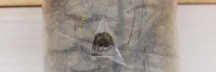
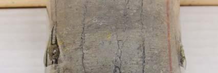
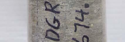
24 APPENDIX C Failed Specimens

25 Figure C-1 Specimen DGR m

26 Figure C-2 Specimen DGR-3, m

27 Figure C-3 Specimen DGR-3, m

28 Figure C-4 Specimen DGR-4, m

29 Figure C-5 Specimen DGR-4, m

30 Figure C-6 Specimen DGR-4, m


31 Figure C-7 Specimen DGR-3, m


32 Figure C-8 Specimen DGR-3, m


33 Figure C-9 Specimen DGR-3, m


34 Figure C-10 Specimen DGR-4, m

35 Figure C-11 Specimen DGR-4, m


36 Figure C-12 Specimen DGR-4, m
37 APPENDIX D Plots of Axial and Diametric Displacement vs. Time
38 Axial Strain Diametric Strain Linear (Axial Strain) Linear (Diametric Strain) Strain, % Time, minutes Figure D-1 Specimen DGR-4, m Axial Strain Diametric Strain Linear (Axial Strain) Linear (Diametric Strain) Strain, % Time, minutes Figure D-2 Specimen DGR-4, m
39 Axial Strain Diametric Strain Linear (Diametric Strain) Linear (Axial Strain) Strain, % Time, minutes Figure D-3 Specimen DGR-4, m Axial Strain Diametric Strain Linear (Diametric Strain) Linear (Axial Strain) Strain, % Time, minutes Figure D-4 Specimen DGR-4,
40 Axial Strain Diametric Strain Linear (Diametric Strain) Linear (Axial Strain) Strain, % Time, minutes Figure D-5 Specimen DGR-4, m Axial Strain Diametric Strain Linear (Diametric Strain) Linear (Axial Strain) Strain, % Time, minutes Figure D-6 Specimen DGR-4, m
41 APPENDIX E Plots of AE Cumulative Hits vs. Time
42 30 27 DGR DGR DGR DGR DGR DGR Cumulative (Hits) Time (min.) Figure E-1 Cumulative AE Hits vs. Time
Supplementary Uniaxial Compressive Strength Testing of DGR-3 and DGR-4 Core
 Technical Report Title: Document ID: Authors: Supplementary Uniaxial Compressive Strength Testing of DGR-3 and DGR-4 Core TR-08-39 B. Gorski, T. Anderson and D. Rodgers CANMET Mining and Mineral Sciences
Laboratory Geomechanical Strength Testing of DGR-1 & DGR-2 Core
 Technical Report Title: Document ID: Authors: Laboratory Geomechanical Strength Testing of DGR-1 & DGR-2 Core TR-7-3 B. Gorski, T. Anderson and T. Conlon CANMET Mining and Mineral Sciences Laboratories,
Laboratory Geomechanical Strength Testing of DGR-2 to DGR-6 Core
 Technical Report Title: Document ID: Authors: Laboratory Geomechanical Strength Testing of DGR-2 to DGR-6 Core TR-9-7 B. Gorski, D. Rodgers and B. Conlon CANMET Mining and Mineral Sciences Laboratories,
Module 5: Failure Criteria of Rock and Rock masses. Contents Hydrostatic compression Deviatoric compression
 FAILURE CRITERIA OF ROCK AND ROCK MASSES Contents 5.1 Failure in rocks 5.1.1 Hydrostatic compression 5.1.2 Deviatoric compression 5.1.3 Effect of confining pressure 5.2 Failure modes in rocks 5.3 Complete
Laboratory Triaxial and Permeability Tests on Tournemire Shale and Cobourg Limestone (Contract : R413.8) FINAL REPORT
 FINAL REPORT") RSP-413.8 Laboratory Triaxial and Permeability Tests on Tournemire Shale and Cobourg Limestone (Contract 87055-14-0209: R413.8) FINAL REPORT M.H.B. Nasseri, Ph.D and R.P. Young, Ph.D University of Toronto
RSP-413.8 Laboratory Triaxial and Permeability Tests on Tournemire Shale and Cobourg Limestone (Contract 87055-14-0209: R413.8) FINAL REPORT M.H.B. Nasseri, Ph.D and R.P. Young, Ph.D University of Toronto
DOWN-HOLE SEISMIC SURVEY AND VERTICAL ELECTRIC SOUNDINGS RABASKA PROJECT, LÉVIS, QUÉBEC. Presented to :
 DOWN-HOLE SEISMIC SURVEY AND VERTICAL ELECTRIC SOUNDINGS RABASKA PROJECT, LÉVIS, QUÉBEC Presented to : TERRATECH 455, René-Lévesque Blvd. West Montreal, Québec HZ 1Z3 Presented by : GEOPHYSICS GPR INTERNATIONAL
Oriented Core Logging of DGR-5 and DGR-6. Steve Gaines, Kenneth Raven and Michael Melaney
 Technical Report Title: Document ID: Authors: Oriented Core Logging of DGR-5 and DGR-6 TR-09-09 Steve Gaines, Kenneth Raven and Michael Melaney Revision: 0 Date: April 8, 2011 DGR Site Characterization
Field Geomechanical Testing of DGR-1 and DGR-2 Core. Steve Gaines & Sean Sterling
 Technical Report Title: Field Geomechanical Testing of DGR-1 and DGR-2 Core Document ID: Authors: TR-07-07 Steve Gaines & Sean Sterling Revision: 1 Date: February 13, 2009 DGR Site Characterization Document
A comprehensive investigation of crack damage anisotropy in Cobourg limestone and its effect on the failure envelope
 A comprehensive investigation of crack damage anisotropy in Cobourg limestone and its effect on the failure envelope E. Ghazvinian, M. Perras, C. Langford & M. Diederichs GeoEngineering Centre, Queen s
Hardened Concrete. Lecture No. 16
 Hardened Concrete Lecture No. 16 Fatigue strength of concrete Modulus of elasticity, Creep Shrinkage of concrete Stress-Strain Plot of Concrete At stress below 30% of ultimate strength, the transition
Experimental study of mechanical and thermal damage in crystalline hard rock
 Experimental study of mechanical and thermal damage in crystalline hard rock Mohammad Keshavarz Réunion Technique du CFMR - Thèses en Mécanique des Roches December, 3 nd 2009 1 Overview Introduction Characterization
Numerical modeling of standard rock mechanics laboratory tests using a finite/discrete element approach
 Numerical modeling of standard rock mechanics laboratory tests using a finite/discrete element approach S. Stefanizzi GEODATA SpA, Turin, Italy G. Barla Department of Structural and Geotechnical Engineering,
Rock Mechanics Laboratory Tests for Petroleum Applications. Rob Marsden Reservoir Geomechanics Advisor Gatwick
 Rock Mechanics Laboratory Tests for Petroleum Applications Rob Marsden Reservoir Geomechanics Advisor Gatwick Summary A wide range of well established and proven laboratory tests are available for petroleum
In-situ Experiments on Excavation Disturbance in JNC s Geoscientific Research Programme
 In-situ Experiments on Excavation Disturbance in JNC s Geoscientific Research Programme H. Matsui, K. Sugihara and T. Sato Japan Nuclear Cycle Development Institute, Japan Summary The HLW disposal program
1.103 CIVIL ENGINEERING MATERIALS LABORATORY (1-2-3) Dr. J.T. Germaine Spring 2004 LABORATORY ASSIGNMENT NUMBER 6
 Dr. J.T. Germaine Spring 2004 LABORATORY ASSIGNMENT NUMBER 6") 1.103 CIVIL ENGINEERING MATERIALS LABORATORY (1-2-3) Dr. J.T. Germaine MIT Spring 2004 LABORATORY ASSIGNMENT NUMBER 6 COMPRESSION TESTING AND ANISOTROPY OF WOOD Purpose: Reading: During this laboratory
1.103 CIVIL ENGINEERING MATERIALS LABORATORY (1-2-3) Dr. J.T. Germaine MIT Spring 2004 LABORATORY ASSIGNMENT NUMBER 6 COMPRESSION TESTING AND ANISOTROPY OF WOOD Purpose: Reading: During this laboratory
Samantha Ramirez, MSE. Stress. The intensity of the internal force acting on a specific plane (area) passing through a point. F 2
 passing through a point. F 2") Samantha Ramirez, MSE Stress The intensity of the internal force acting on a specific plane (area) passing through a point. Δ ΔA Δ z Δ 1 2 ΔA Δ x Δ y ΔA is an infinitesimal size area with a uniform force
Samantha Ramirez, MSE Stress The intensity of the internal force acting on a specific plane (area) passing through a point. Δ ΔA Δ z Δ 1 2 ΔA Δ x Δ y ΔA is an infinitesimal size area with a uniform force
APPLICATION OF 1D HYDROMECHANICAL COUPLING IN TOUGH2 TO A DEEP GEOLOGICAL REPOSITORY GLACIATION SCENARIO
 PROCEEDINGS, TOUGH Symposium 2015 Lawrence Berkeley National Laboratory, Berkeley, California, September 28-30, 2015 APPLICATION OF 1D HYDROMECHANICAL COUPLING IN TOUGH2 TO A DEEP GEOLOGICAL REPOSITORY
Geomechanical Characterization of a Montney Equivalent Outcrop
 Is (MPa) Geomechanical Characterization of a Montney Equivalent Outcrop Scott H McKean, Mason MacKay, Dr. Jeffrey Priest University of Calgary Summary A variety of geomechanical tests (point load strength,
Acquisition of Complete Acoustic Emission Amplitude Records during Rock Fracture Experiments
 Acquisition of Complete Acoustic Emission Amplitude Records during Rock Fracture Experiments S.D. Goodfellow 1, J.W. Flynn 2, J.M. Reyes-Montes 2, M.H.B. Nasseri 1 and R.P. Young 1 1 Department of Civil
DAMAGE CHARACTERIZATION OF COAL MEASURE ROCKS UNDER UNIAXIAL COMPRESSION
 DAMAGE CHARACTERIZATION OF COAL MEASURE ROCKS UNDER UNIAXIAL COMPRESSION and Michael Alber Engineering Geology Group Ruhr University Bochum, Germany ABSTRACT The identification of burst-prone rock layers
Compilation and Consolidation of Field and Laboratory Data for Hydrogeological Properties
 Technical Report Title: Document ID: Author: Compilation and Consolidation of Field and Laboratory Data for Hydrogeological Properties TR-08-10 Robert Walsh Revision: 1 Date: April 1, 2011 DGR Site Characterization
20. Rheology & Linear Elasticity
 I Main Topics A Rheology: Macroscopic deformation behavior B Linear elasticity for homogeneous isotropic materials 10/29/18 GG303 1 Viscous (fluid) Behavior http://manoa.hawaii.edu/graduate/content/slide-lava
QUANTITATIVE DAMAGE ESTIMATION OF CONCRETE CORE BASED ON AE RATE PROCESS ANALYSIS
 QUANTITATIVE DAMAGE ESTIMATION OF CONCRETE CORE BASED ON AE RATE PROCESS ANALYSIS MASAYASU OHTSU and TETSUYA SUZUKI 1 Kumamoto University, Kumamoto 860-8555, Japan 2 Nippon Suiko Consultants Co., Kumamoto
ATTEMPT TO MEASURE VELOCITY AT LOW FREQUENCY BY MODIFIED TRI-AXIAL DESTRUCTIVE INSTRUMENT
 SCA2010-40 1/6 ATTEMPT TO MEASURE VELOCITY AT LOW FREQUENCY BY MODIFIED TRI-AXIAL DESTRUCTIVE INSTRUMENT Fumio Kono, Shigenobu Onozuka, Satoshi Izumotani and Naoyuki Shimoda Japan Oil, Gas and Metals National
Title. Author(s)Akm Badrul, Alam; Fujii, Yoshiaki; Aramaki, Noritaka. CitationProceedings of Japan Symposium on Rock Mechanics, 14
Akm Badrul, Alam; Fujii, Yoshiaki; Aramaki, Noritaka. CitationProceedings of Japan Symposium on Rock Mechanics, 14") Title Water migration into underground cavern considering Author(s)Akm Badrul, Alam; Fujii, Yoshiaki; Aramaki, Noritaka CitationProceedings of Japan Symposium on Rock Mechanics, 4 Issue Date 207-0-0 Doc
Title Water migration into underground cavern considering Author(s)Akm Badrul, Alam; Fujii, Yoshiaki; Aramaki, Noritaka CitationProceedings of Japan Symposium on Rock Mechanics, 4 Issue Date 207-0-0 Doc
NORMAL STRESS. The simplest form of stress is normal stress/direct stress, which is the stress perpendicular to the surface on which it acts.
 NORMAL STRESS The simplest form of stress is normal stress/direct stress, which is the stress perpendicular to the surface on which it acts. σ = force/area = P/A where σ = the normal stress P = the centric
An Acoustic Emission Approach to Assess Remaining Useful Life of Aging Structures under Fatigue Loading PI: Mohammad Modarres
 An Acoustic Emission Approach to Assess Remaining Useful Life of Aging Structures under Fatigue Loading PI: Mohammad Modarres Outline Objective Motivation, acoustic emission (AE) background, approaches
Lecture 8 Viscoelasticity and Deformation
 Read: pg 130 168 (rest of Chpt. 4) 1 Poisson s Ratio, µ (pg. 115) Ratio of the strain in the direction perpendicular to the applied force to the strain in the direction of the applied force. For uniaxial
Standard Test Method for Determination of the Point Load Strength Index of Rock 1
 Designation: D 5731 95 AMERICAN SOCIETY FOR TESTING AND MATERIALS 100 Barr Harbor Dr., West Conshohocken, PA 19428 Reprinted from the Annual Book of ASTM Standards. Copyright ASTM Standard Test Method
Part 7. Nonlinearity
 Part 7 Nonlinearity Linear System Superposition, Convolution re ( ) re ( ) = r 1 1 = r re ( 1 + e) = r1 + r e excitation r = r() e response In the time domain: t rt () = et () ht () = e( τ) ht ( τ) dτ
SHEAR STRENGTH OF SOIL UNCONFINED COMPRESSION TEST
 SHEAR STRENGTH OF SOIL DEFINITION The shear strength of the soil mass is the internal resistance per unit area that the soil mass can offer to resist failure and sliding along any plane inside it. INTRODUCTION
Mechanical properties 1 Elastic behaviour of materials
 MME131: Lecture 13 Mechanical properties 1 Elastic behaviour of materials A. K. M. B. Rashid Professor, Department of MME BUET, Dhaka Today s Topics Deformation of material under the action of a mechanical
3D simulations of an injection test done into an unsaturated porous and fractured limestone
 3D simulations of an injection test done into an unsaturated porous and fractured limestone A. Thoraval *, Y. Guglielmi, F. Cappa INERIS, Ecole des Mines de Nancy, FRANCE *Corresponding author: Ecole des
Evaluation of in-plane orthotropic elastic constants of paper and paperboard
 Evaluation of in-plane orthotropic elastic constants of paper and paperboard T. Yokoyama and K. Nakai Department of Mechanical Engineering, Okayama University of Science - Ridai-cho, Okayama 7-5, Japan
ME 2570 MECHANICS OF MATERIALS
 ME 2570 MECHANICS OF MATERIALS Chapter III. Mechanical Properties of Materials 1 Tension and Compression Test The strength of a material depends on its ability to sustain a load without undue deformation
Effect of intermediate principal stresses on compressive strength of Phra Wihan sandstone
 Rock Mechanics, Fuenkajorn & Phien-wej (eds) 211. ISBN 978 974 533 636 Effect of intermediate principal stresses on compressive strength of Phra Wihan sandstone T. Pobwandee & K. Fuenkajorn Geomechanics
STANDARD SAMPLE. Reduced section " Diameter. Diameter. 2" Gauge length. Radius
 MATERIAL PROPERTIES TENSILE MEASUREMENT F l l 0 A 0 F STANDARD SAMPLE Reduced section 2 " 1 4 0.505" Diameter 3 4 " Diameter 2" Gauge length 3 8 " Radius TYPICAL APPARATUS Load cell Extensometer Specimen
Exercise: concepts from chapter 8
 Reading: Fundamentals of Structural Geology, Ch 8 1) The following exercises explore elementary concepts associated with a linear elastic material that is isotropic and homogeneous with respect to elastic
Project PAJ2 Dynamic Performance of Adhesively Bonded Joints. Report No. 3 August Proposed Draft for the Revision of ISO
 NPL Report CMMT(A)81 Project PAJ2 Dynamic Performance of Adhesively Bonded Joints Report No. 3 August 1997 Proposed Draft for the Revision of ISO 11003-2 Adhesives - Determination of Shear Behaviour of
Challenges related to standardized detection of crack initiation thresholds for lower-bound or ultra-long-term strength prediction of rock
 Challenges related to standardized detection of crack initiation thresholds for lower-bound or ultra-long-term strength prediction of rock E. Ghazvinian*, M. Diederichs* & J. Archibald *Dept. of Geological
FATIGUE DAMAGE PROGRESSION IN PLASTICS DURING CYCLIC BALL INDENTATION
 FATIGUE DAMAGE PROGRESSION IN PLASTICS DURING CYCLIC BALL INDENTATION AKIO YONEZU, TAKAYASU HIRAKAWA, TAKESHI OGAWA and MIKIO TAKEMOTO Department of Mechanical Engineering, College of Science and Engineering,
Chapter 7. Highlights:
 Chapter 7 Highlights: 1. Understand the basic concepts of engineering stress and strain, yield strength, tensile strength, Young's(elastic) modulus, ductility, toughness, resilience, true stress and true
XRD Mineralogical Analysis of DGR-1 and DGR-2 Core. Aniceta Skowron & Eric Hoffman Activation Laboratories Ltd., Ancaster, Ontario
 Technical Report Title: Document ID: Authors: XRD Mineralogical Analysis of DGR-1 and DGR-2 Core TR-8-1 Aniceta Skowron & Eric Hoffman Activation Laboratories Ltd., Ancaster, Ontario Revision: Date: April
EMA 3702 Mechanics & Materials Science (Mechanics of Materials) Chapter 2 Stress & Strain - Axial Loading
 Chapter 2 Stress & Strain - Axial Loading") MA 3702 Mechanics & Materials Science (Mechanics of Materials) Chapter 2 Stress & Strain - Axial Loading MA 3702 Mechanics & Materials Science Zhe Cheng (2018) 2 Stress & Strain - Axial Loading Statics
MA 3702 Mechanics & Materials Science (Mechanics of Materials) Chapter 2 Stress & Strain - Axial Loading MA 3702 Mechanics & Materials Science Zhe Cheng (2018) 2 Stress & Strain - Axial Loading Statics
INFLUENCE OF WATER-SOAKING TIME ON THE ACOUSTIC EMISSION CHARACTERISTICS AND SPATIAL FRACTAL DIMENSIONS OF COAL UNDER UNIAXIAL COMPRESSION
 THERMAL SCIENCE: Year 07, Vol., Suppl., pp. S37-S334 S37 INFLUENCE OF WATER-SOAKING TIME ON THE ACOUSTIC EMISSION CHARACTERISTICS AND SPATIAL FRACTAL DIMENSIONS OF COAL UNDER UNIAXIAL COMPRESSION by Zheqiang
Task 1 - Material Testing of Bionax Pipe and Joints
 Task 1 - Material Testing of Bionax Pipe and Joints Submitted to: Jeff Phillips Western Regional Engineer IPEX Management, Inc. 20460 Duncan Way Langley, BC, Canada V3A 7A3 Ph: 604-534-8631 Fax: 604-534-7616
ME 243. Mechanics of Solids
 ME 243 Mechanics of Solids Lecture 2: Stress and Strain Ahmad Shahedi Shakil Lecturer, Dept. of Mechanical Engg, BUET E-mail: sshakil@me.buet.ac.bd, shakil6791@gmail.com Website: teacher.buet.ac.bd/sshakil
Lecture #2: Split Hopkinson Bar Systems
 Lecture #2: Split Hopkinson Bar Systems by Dirk Mohr ETH Zurich, Department of Mechanical and Process Engineering, Chair of Computational Modeling of Materials in Manufacturing 2015 1 1 1 Uniaxial Compression
MEMORANDUM SUBJECT: CERTIFICATE IN ROCK MECHANICS PAPER 1 : THEORY SUBJECT CODE: COMRMC MODERATOR: H YILMAZ EXAMINATION DATE: OCTOBER 2017 TIME:
 MEMORANDUM SUBJECT: CERTIFICATE IN ROCK MECHANICS PAPER 1 : THEORY EXAMINER: WM BESTER SUBJECT CODE: COMRMC EXAMINATION DATE: OCTOBER 2017 TIME: MODERATOR: H YILMAZ TOTAL MARKS: [100] PASS MARK: (60%)
**********************************************************************
 Department of Civil and Environmental Engineering School of Mining and Petroleum Engineering 3-33 Markin/CNRL Natural Resources Engineering Facility www.engineering.ualberta.ca/civil Tel: 780.492.4235
N = Shear stress / Shear strain
 UNIT - I 1. What is meant by factor of safety? [A/M-15] It is the ratio between ultimate stress to the working stress. Factor of safety = Ultimate stress Permissible stress 2. Define Resilience. [A/M-15]
The University of Melbourne Engineering Mechanics
 The University of Melbourne 436-291 Engineering Mechanics Tutorial Four Poisson s Ratio and Axial Loading Part A (Introductory) 1. (Problem 9-22 from Hibbeler - Statics and Mechanics of Materials) A short
University of Sheffield The development of finite elements for 3D structural analysis in fire
 The development of finite elements for 3D structural analysis in fire Chaoming Yu, I. W. Burgess, Z. Huang, R. J. Plank Department of Civil and Structural Engineering StiFF 05/09/2006 3D composite structures
Unit I Stress and Strain
 Unit I Stress and Strain Stress and strain at a point Tension, Compression, Shear Stress Hooke s Law Relationship among elastic constants Stress Strain Diagram for Mild Steel, TOR steel, Concrete Ultimate
Experimental Assessment of Rock Cutting Characteristics by Strength-Driven Mechanism. H Munoz, A Taheri & E Chanda
 Experimental Assessment of Rock Cutting Characteristics by Strength-Driven Mechanism H Munoz, A Taheri & E Chanda AusIMM Africa Australia Technical Mining Conference, Jun 11-12 215 Adelaide, Australia
The science of elasticity
 The science of elasticity In 1676 Hooke realized that 1.Every kind of solid changes shape when a mechanical force acts on it. 2.It is this change of shape which enables the solid to supply the reaction
INTRODUCTION TO STRAIN
 SIMPLE STRAIN INTRODUCTION TO STRAIN In general terms, Strain is a geometric quantity that measures the deformation of a body. There are two types of strain: normal strain: characterizes dimensional changes,
OP-023. INTERPRETATION OF INSTRUMENTED TEST PILE RESULT
 INTERPRETATION OF INSTRUMENTED TEST PILE RESULT Page 1 of 9 WORK INSTRUCTIONS FOR ENGINEERS GSJ Compiled by : Checked by KYW : LSS Approved by : OP-23. INTERPRETATION OF INSTRUMENTED TEST PILE RESULT INTERPRETATION
DEVELOPMENT OF DROP WEIGHT IMPACT TEST MACHINE
 CHAPTER-8 DEVELOPMENT OF DROP WEIGHT IMPACT TEST MACHINE 8.1 Introduction The behavior of materials is different when they are subjected to dynamic loading [9]. The testing of materials under dynamic conditions
MECE 3321 MECHANICS OF SOLIDS CHAPTER 3
 MECE 3321 MECHANICS OF SOLIDS CHAPTER 3 Samantha Ramirez TENSION AND COMPRESSION TESTS Tension and compression tests are used primarily to determine the relationship between σ avg and ε avg in any material.
DEVELOPMENT OF AUTOMATIC CONTROL OF MULTI-STAGE TRIAXIAL TESTS AT THE UNIVERSITY OF MISKOLC
 Geosciences and Engineering, Vol. 2, No. 3 (2013), pp. 37 43. DEVELOPMENT OF AUTOMATIC CONTROL OF MULTI-STAGE TRIAXIAL TESTS AT THE UNIVERSITY OF MISKOLC BALÁZS CSUHANICS ÁKOS DEBRECZENI Institute of Mining
Temperature Dependent Mechanical Properties of Reservoir s Overburden Rocks During SAGD Process
 Temperature Dependent Mechanical Properties of Reservoir s Overburden Rocks During SAGD Process Bo Zhao 1, Shangqi Liu 2, Bo Huang 3, and Yang Liu 4 and Guangqing Zhang *,5 1,5 China University of Petroleum
[5] Stress and Strain
![[5] Stress and Strain](/thumbs/95/123344550.jpg "[5] Stress and Strain") [5] Stress and Strain Page 1 of 34 [5] Stress and Strain [5.1] Internal Stress of Solids [5.2] Design of Simple Connections (will not be covered in class) [5.3] Deformation and Strain [5.4] Hooke s Law
[5] Stress and Strain Page 1 of 34 [5] Stress and Strain [5.1] Internal Stress of Solids [5.2] Design of Simple Connections (will not be covered in class) [5.3] Deformation and Strain [5.4] Hooke s Law
ON THE FACE STABILITY OF TUNNELS IN WEAK ROCKS
 33 rd 33 Annual rd Annual General General Conference conference of the Canadian of the Canadian Society for Society Civil Engineering for Civil Engineering 33 e Congrès général annuel de la Société canadienne
Theory at a Glance (for IES, GATE, PSU)
") 1. Stress and Strain Theory at a Glance (for IES, GATE, PSU) 1.1 Stress () When a material is subjected to an external force, a resisting force is set up within the component. The internal resistance force
1. Stress and Strain Theory at a Glance (for IES, GATE, PSU) 1.1 Stress () When a material is subjected to an external force, a resisting force is set up within the component. The internal resistance force
ENSC387: Introduction to Electromechanical Sensors and Actuators LAB 3: USING STRAIN GAUGES TO FIND POISSON S RATIO AND YOUNG S MODULUS
 ENSC387: Introduction to Electromechanical Sensors and Actuators LAB 3: USING STRAIN GAUGES TO FIND POISSON S RATIO AND YOUNG S MODULUS 1 Introduction... 3 2 Objective... 3 3 Supplies... 3 4 Theory...
STRAIN GAUGES YEDITEPE UNIVERSITY DEPARTMENT OF MECHANICAL ENGINEERING
 STRAIN GAUGES YEDITEPE UNIVERSITY DEPARTMENT OF MECHANICAL ENGINEERING 1 YEDITEPE UNIVERSITY ENGINEERING FACULTY MECHANICAL ENGINEERING LABORATORY 1. Objective: Strain Gauges Know how the change in resistance
Mechanical Properties of Materials
 Mechanical Properties of Materials Strains Material Model Stresses Learning objectives Understand the qualitative and quantitative description of mechanical properties of materials. Learn the logic of
Solid Mechanics Chapter 1: Tension, Compression and Shear
 Solid Mechanics Chapter 1: Tension, Compression and Shear Dr. Imran Latif Department of Civil and Environmental Engineering College of Engineering University of Nizwa (UoN) 1 Why do we study Mechanics
Geoscientific Verification Plan
 Geoscientific Verification Plan March 2011 Prepared by: Nuclear Waste Management Organization NWMO DGR-TR-2011-38 Geoscientific Verification Plan March 2011 Prepared by: Nuclear Waste Management Organization
1.8 Unconfined Compression Test
 1-49 1.8 Unconfined Compression Test - It gives a quick and simple measurement of the undrained strength of cohesive, undisturbed soil specimens. 1) Testing method i) Trimming a sample. Length-diameter
Stress-Strain Behavior
 Stress-Strain Behavior 6.3 A specimen of aluminum having a rectangular cross section 10 mm 1.7 mm (0.4 in. 0.5 in.) is pulled in tension with 35,500 N (8000 lb f ) force, producing only elastic deformation.
MECHANICS OF MATERIALS
 Third E CHAPTER 2 Stress MECHANICS OF MATERIALS Ferdinand P. Beer E. Russell Johnston, Jr. John T. DeWolf Lecture Notes: J. Walt Oler Texas Tech University and Strain Axial Loading Contents Stress & Strain:
Assessment of Porosity Data and Gas Phase Presence in DGR Cores
 Technical Report Title: Document ID: Authors: Assessment of Porosity Data and Gas Phase Presence in DGR Cores TR-08-34 Sean Sterling, Richard Jackson, Robert Walsh, Dru Heagle, and Ian Clark (University
CIVE 2700: Civil Engineering Materials Fall Lab 2: Concrete. Ayebabomo Dambo
 CIVE 2700: Civil Engineering Materials Fall 2017 Lab 2: Concrete Ayebabomo Dambo Lab Date: 7th November, 2017 CARLETON UNIVERSITY ABSTRACT Concrete is a versatile construction material used in bridges,
Ground Support in Mining and Underground Construction
 Ground Support in Mining and Underground Construction Proceedings of the Fifth International Symposium on Ground Support 28-30 September 2004, Perth, Western Australia Edited by Ernesto Villaescusa Yves
Rock Material. Chapter 3 ROCK MATERIAL HOMOGENEITY AND INHOMOGENEITY CLASSIFICATION OF ROCK MATERIAL
 Chapter 3 Rock Material In all things of nature there is something of the marvelous. Aristotle ROCK MATERIAL The term rock material refers to the intact rock within the framework of discontinuities. In
Fig. 1. Different locus of failure and crack trajectories observed in mode I testing of adhesively bonded double cantilever beam (DCB) specimens.
 specimens.") a). Cohesive Failure b). Interfacial Failure c). Oscillatory Failure d). Alternating Failure Fig. 1. Different locus of failure and crack trajectories observed in mode I testing of adhesively bonded double
a). Cohesive Failure b). Interfacial Failure c). Oscillatory Failure d). Alternating Failure Fig. 1. Different locus of failure and crack trajectories observed in mode I testing of adhesively bonded double
Post Graduate Diploma in Mechanical Engineering Computational mechanics using finite element method
 9210-220 Post Graduate Diploma in Mechanical Engineering Computational mechanics using finite element method You should have the following for this examination one answer book scientific calculator No
Using the Timoshenko Beam Bond Model: Example Problem
 Using the Timoshenko Beam Bond Model: Example Problem Authors: Nick J. BROWN John P. MORRISSEY Jin Y. OOI School of Engineering, University of Edinburgh Jian-Fei CHEN School of Planning, Architecture and
Class XI Chapter 9 Mechanical Properties of Solids Physics
 Book Name: NCERT Solutions Question : A steel wire of length 4.7 m and cross-sectional area 5 3.0 0 m stretches by the same 5 amount as a copper wire of length 3.5 m and cross-sectional area of 4.0 0 m
12/8/2009. Prof. A.K.M.B. Rashid Department of MME BUET, Dhaka
 Prof. A.K.M.B. Rashid Department of MME BUET, Dhaka Introduction and classes of properties Case studies showing selection of the right material for the job Deformation of material under the action of a
DEM simulation of fracture process of inherently anisotropic rock under Brazilian test condition
 Title DEM simulation of fracture process of inherently anisotropic rock under Brazilian test condition Author(s) Kwok, CY; Duan, K Citation The 49th US Rock Mechanics / Geomechanics Symposium, San Francisco,
COMPARISON OF UNCONFINED COMPRESSIVE STRENGTHS AND ACOUSTIC EMISSIONS OF ESTONIAN OIL SHALE AND BRITTLE ROCKS
 Oil Shale, 2018, Vol. 35, No. 1, pp. 26 38 ISSN 0208-189X doi: https//doi.org/10.3176/oil.2018.1.02 2018 Estonian Academy Publishers COMPARISON OF UNCONFINED COMPRESSIVE STRENGTHS AND ACOUSTIC EMISSIONS
Geomechanical Controls on Hydraulic Fracturing in the Bakken Fm, SK
 Geomechanical Controls on Hydraulic Fracturing in the Bakken Fm, SK Chris Hawkes University of Saskatchewan Tight Oil Optimization Conference, Calgary AB, March 12, 2015 Outline Overview of Geomechanical
Module III - Macro-mechanics of Lamina. Lecture 23. Macro-Mechanics of Lamina
 Module III - Macro-mechanics of Lamina Lecture 23 Macro-Mechanics of Lamina For better understanding of the macromechanics of lamina, the knowledge of the material properties in essential. Therefore, the
Mathematical Modelling of a Fault Slip Induced by Water Injection
 Mathematical Modelling of a Fault Slip Induced by Water Injection T. S. Nguyen, 1 J.Rutqvist 2 and Y. Gugliemi 2 1 Canadian Nuclear Safety Commission 2 Lawrence Berkeley National Laboratory ComGeo IV Symposium
Estimation of Seismic Damage for Optimum Management of Irrigation Infrastructures in Service Conditions using Elastic Waves Information
 Estimation of Seismic Damage for Optimum Management of Irrigation Infrastructures in Service Conditions using Elastic Waves Information Tetsuya Suzuki Faculty of Agriculture, Niigata University 950-2181,
BIAXIAL STRENGTH INVESTIGATION OF CFRP COMPOSITE LAMINATES BY USING CRUCIFORM SPECIMENS
 BIAXIAL STRENGTH INVESTIGATION OF CFRP COMPOSITE LAMINATES BY USING CRUCIFORM SPECIMENS H. Kumazawa and T. Takatoya Airframes and Structures Group, Japan Aerospace Exploration Agency 6-13-1, Ohsawa, Mitaka,
STRENGTH OF MATERIALS-I. Unit-1. Simple stresses and strains
 STRENGTH OF MATERIALS-I Unit-1 Simple stresses and strains 1. What is the Principle of surveying 2. Define Magnetic, True & Arbitrary Meridians. 3. Mention different types of chains 4. Differentiate between
Investigation on the Anisotropic Mechanical Behaviour of the Callovo- Oxfordian Clay Rock
 Investigation on the Anisotropic Mechanical Behaviour of the Callovo- Oxfordian Clay Rock Final Report within the framework of ANDRA/GRS cooperation programme GRS - 36 Gesellschaft für Anlagenund Reaktorsicherheit
 Question 9.1: A steel wire of length 4.7 m and cross-sectional area 3.0 10 5 m 2 stretches by the same amount as a copper wire of length 3.5 m and cross-sectional area of 4.0 10 5 m 2 under a given load.
Development of a Rock Strength Database
 Development of a Rock Strength Database Joseph Labuz, Principal Investigator Department of Civil, Environmental, and Geo- Engineering University of Minnesota June 218 Research Project Final Report 218-19
LECTURE NO. 4-5 INTRODUCTION ULTRASONIC * PULSE VELOCITY METHODS
 LECTURE NO. 4-5 ULTRASONIC * PULSE VELOCITY METHODS Objectives: To introduce the UPV methods To briefly explain the theory of pulse propagation through concrete To explain equipments, procedures, calibrations,
Introduction and Background
 Introduction and Background Itasca Consulting Group, Inc. (Itasca) has been participating in the geomechanical design of the underground 118-Zone at the Capstone Minto Mine (Minto) in the Yukon, in northwestern
Research Article EffectsofCyclicLoadingontheMechanicalPropertiesofMature Bedding Shale
 Advances in Civil Engineering Volume 218, Article ID 8985973, 9 pages https://doi.org/1.1155/218/8985973 Research Article EffectsofCyclicLoadingontheMechanicalPropertiesofMature Bedding Shale Yintong Guo,
Lab Exercise #5: Tension and Bending with Strain Gages
 Lab Exercise #5: Tension and Bending with Strain Gages Pre-lab assignment: Yes No Goals: 1. To evaluate tension and bending stress models and Hooke s Law. a. σ = Mc/I and σ = P/A 2. To determine material
The Mine Geostress Testing Methods and Design
 Open Journal of Geology, 2014, 4, 622-626 Published Online December 2014 in SciRes. http://www.scirp.org/journal/ojg http://dx.doi.org/10.4236/ojg.2014.412046 The Mine Geostress Testing Methods and Design
Mechanics of Earthquakes and Faulting
 Mechanics of Earthquakes and Faulting www.geosc.psu.edu/courses/geosc508 Standard Solids and Fracture Fluids: Mechanical, Chemical Effects Effective Stress Dilatancy Hardening and Stability Mead, 1925
Class XI Physics. Ch. 9: Mechanical Properties of solids. NCERT Solutions
 Downloaded from Class XI Physics Ch. 9: Mechanical Properties of solids NCERT Solutions Page 242 Question 9.1: A steel wire of length 4.7 m and cross-sectional area 3.0 10 5 m 2 stretches by the same amount