Lecture Note 8-1 Hydraulic Systems. System Analysis Spring
|
|
|
- Christopher Lamb
- 5 years ago
- Views:
Transcription
1 Lecture Note 8-1 Hydraulic Systems 1
2 Vehicle Model - Brake Model Brake Model Font Wheel Brake Pedal Vacuum Booster Master Cylinder Proportionnig Valve Vacuum Booster Rear Wheel Master Cylinder Proportioning Valve Brake Pedal Fundamental structure of a hydraulic brake 2
3 Conservation of Mass, Force and Pressure m q q mi mo i) Volume A dx A dx dx A A2 iii) Force f p A f dx ii) Pressue p p gh pa A f f ( P P) A1 L L A f f f L2 L2 A1 3
4 Hydraulic Excavator Arm Dump Boom Up Arm Crowd Bucket Crowd Boom Down Swing( 선회 ) Bucke t Dump Travel( 주행 ) 4


5 유압굴삭기회로도 5
 Brake Pedal 4 ) Rear Brake Lines 5 ) Stop Light Switch")
 Brake Warning Lamp 9 ) Brake Fluid 10) Brake Pad 11) Master")
6 Hydraulic Brake Systems Brake System 1 ) Wheel Cylinder 2 ) Brake Light 3 ) Brake Pedal 4 ) Rear Brake Lines 5 ) Stop Light Switch (Mechanical) 6 ) Front/Rear Balance Valve 7 ) Pressure Differentiavl Valve 8 ) Brake Warning Lamp 9 ) Brake Fluid 10) Brake Pad 11) Master Cylinder 6
7 Vehicle Model - Brake Model Brake Model Font Wheel Brake Pedal Vacuum Booster Master Cylinder Proportionnig Valve Vacuum Booster Rear Wheel Master Cylinder Proportioning Valve Brake Pedal Fundamental structure of a hydraulic brake 7


8 Applications of Fluid Power Pneumatically controlled dexterous hand Space shuttle Columbia Hydraulically powered dexterous arm Space shuttle vehicle 8


9 Applications of Fluid Power Hydraulically powered Sky-tram Hydraulic power brush drive Hydraulically driven turntable Oceanography 9


10 Automatic Transmission 10

11 Press 11


12 Linear Actuators Motion Simulator Press Airplane Robot 12


13 Hydraulic Systems : Landing Gear System Landing gear system of AIRBUS A330 13
14 Hydraulic Systems Hydraulic pump Control valve Tank P1 P2 Load Hydraulic actuator (70 ~ 210 bar) F A ( P ) P 1 P2 14
15 Why hydraulic? Internal combustion Engine Turbine Electric motor Hydraulic actuator 15
16 Why hydraulic? 1. smaller and lighter horsepower to weight ratio > 2 hp/lb 2. heat/lubrication long component life 3. no saturation and losses - saturation and losses in magnetic materials of electrical machine - torque limit only by safe stress levels 4. high natural frequency/high speed of response/high loop gains - electrical motors, a simple lag device from applied voltage to speed 5. dynamic breaking with relief valve without damage 16
17 Disadvantages 1. not so readily available 2. small allowable tolerances result in high costs 3. hydraulic fluids imposes upper temperature limit. 4. fluid contamination: dirt and contamination 5. basic design procedures are lacking and difficult, complexity of hydraulic control analysis 6. not so flexible, linear, accurate, and inexpensive as electronic and/or electromechanical devices 17

18 Primary Functions of a Hydraulic Fluid 18
19 Conservation of Mass, Force and Pressure m q q mi mo i) Volume A dx A dx dx A A2 iii) Force f p A f dx ii) Pressue p p gh pa A f f ( P P) A1 L L A f f f L2 L2 A1 19

 noisy at relatively high")
20 Gear Pumps (External) fixed displacement pump uses spur gear (teeth are parallel to the axis of the gear) noisy at relatively high speeds 20


21 Internal Gear Pump 21


22 Internal Gear Pump Gerotor Pump 22

23 Internal Gear Pump Lobe Pump 23


24 Simple Vane Pump 24

25 Balanced Vane Pump 25


26 Piston Pump (Swash Plate Type) 26


27 Piston Pump 27

28 Pump Electric Motor or Engine 28
29 Hydraulic Pump the heart of a hydraulic system converts mechanical energy into hydraulic energy hydrostatic pump Displacement the amount of fluid ejected per revolution unit: cm 3 /rev, cc/rev, cm 3 /rad, cc/rad 29
30 Pump Torque Mechanical power supplied to pump H m T Hydraulic power delivered by pump Therefore H p PQ P : pressure rise across the pump Q : delivery rate T PQ P D T th th p th PD p 여기서D p : 펌프배제용적[ m3/ rad] 30
31 Hydraulic Motors and Actuators 31

32 Hydraulic Systems : Valve-motor Combination 32


33 Application of Hydraulic Motors 33

34 Gear Motors 34
35 Hydraulic Systems : Valve-piston Combination Valve-piston combination 35
36 Hydraulic Excavator Arm Dump Boom Up Arm Crowd Bucket Crowd Boom Down Swing( 선회 ) Bucke t Dump Travel( 주행 ) 36


37 Hydraulic Excavator 37

38 Automotive Application Active Suspension 38
39 Rough terrain forklift driven by hydraulic cylinders 39

40 Double-acting Cylinder Design 40


41 Cylinder Construction 41
42 Types of Valves: shearing elements 42
43 Types of Valves: seating elements 43

44 Directional Control Valve 44

45 Hydraulic Systems : Single Stage Electrohydraulic Servovalve Schematic of a single stage electrohydraulic servovalve connected to a motor with inertia load 45


46 Solenoid-Actuated Valves Solenoid-actuated, three-position, spring-centered, four-way, directional control valve Single solenoid-actuated, two-position, spring-offset, four-way, directional control valve 46
47 Operation of Solenoid to Shift of Valve 47

48 Hydraulic Systems : Two-stage Electrohydraulic Servovalve Schematic of a twostage electrohydraulic servovalve with force feedback controlling a motor with inertia load 48


49 Solenoid-controlled, Pilot-operated Valve 49


50 Servo Valve Structure Moog 760 Series Moog 30 Series 50


51 Operation of Servo Valve N N N S S S 51
52 Operation of Servo Valve: Torque Torque Motor Motor Hydraulic Amplifier 52

53 Operation of Servo Valve: Valve Valve Spool Spool 53
54 Hydraulic Servo Systems 54
 Bucke t Dump Travel( 주행 )")
55 Hydraulic Excavator Arm Dump Boom Up Arm Crowd Bucket Crowd Boom Down Swing( 선회 ) Bucke t Dump Travel( 주행 ) 55
56 Hydraulic Systems : Valve-piston Combination Valve-piston combination 56

57 Operation of Solenoid to Shift of Valve 57
58 Hydraulic Servo System : Compressibility V P1 1 V 2 P2 V P V 1 where, Compressibility PV mrt 1 P V V P dp, V V V ( V V ) dv dp V KB ; Bulk modulus dv dp dv KB dv V V dp 1 dv KB dt V dt 58

59 59
60 Basic Modeling of Dynamic Cylinder Generalized Flow - Continuity equation Q Q 2 dv dt dv dt 1 2 V1 e V2 e dp dt 1 dp dt 2 Q 1 A u 1 V1 e dp dt 1 Q 2 A u 2 V2 e dp dt 2 Equation of motion P 1 A 1 P2 A2 m dv dt bv f L Q Q 1 2 P P 1 2 V1 V2 A1 A2 v f L load mass m 60
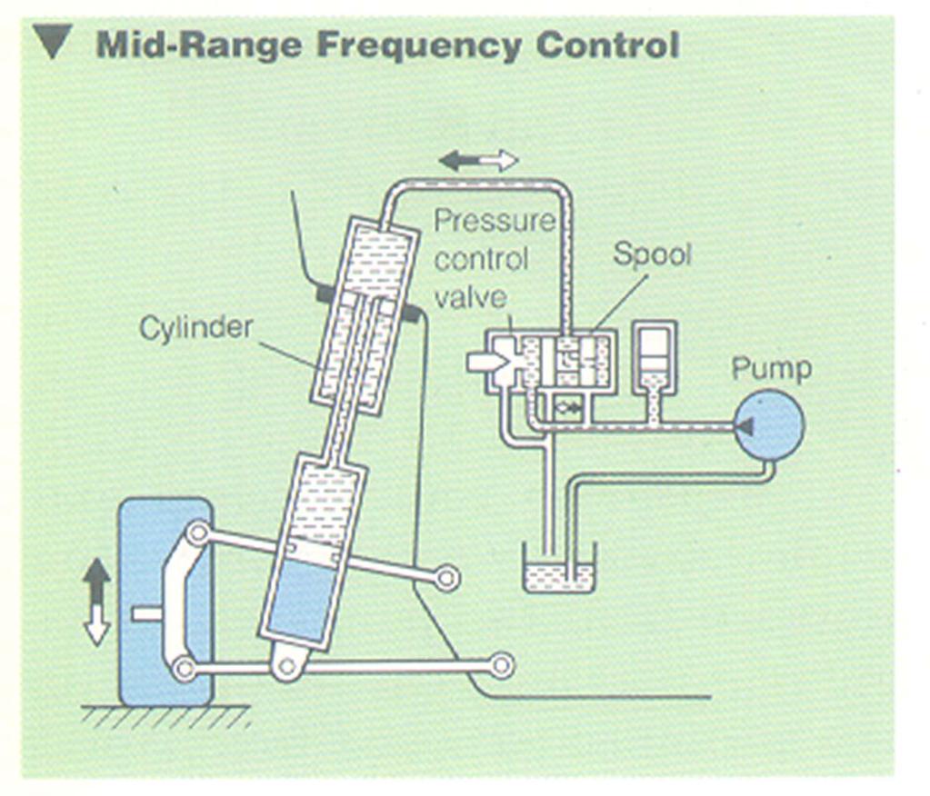
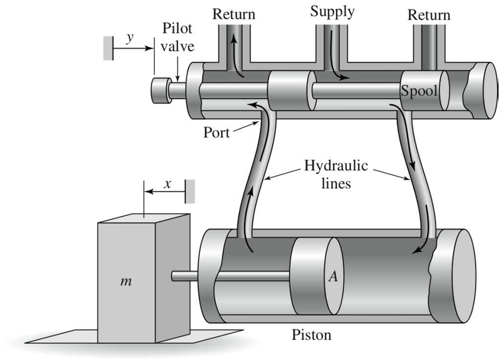
61 Hydraulic Servo System x P0 PS P0 spool PS : supply pressure servo system y Q Q 2 1 P2 P1 piston ( 1 ) d S / Q C ax P P m s a : area gradient, x : displacement : density, C : discharge coefficient d 2 Q2 Cd ax ( P2 P0 ) 2 Cd ax P2 ( P0 0) 61
62 Hydraulic Servo System no leakage, no compressibility Q Q P P P P P P 1 2 s 1 2 s 1 2 P PP P P P 2 P, P P 2P L 1 2 S L 1 S L 2 P P P P P, P PS PL QQ1 Q2 C ax Cx P P 2 dy Q A Cx P P dt dy dt d S L P S L Cx P P S L S L S L
63 Hydraulic Servo System dy Cx PS PL, y yy, xxx, PL PL PL dt dy f f f( x, PL ) ( x x ) ( PL PL ) x PL x PL dt x P dy 1 1 C PS PL ( x x ) ( Cx ) ( PL PL ) dt 2 P P dy if x 0, PL 0, 0 dt dy dt C P x K x S 1 Y() s TF. X () s K S 1 L S L 63
64 Hydraulic Servo System x 0, A A 0 P 0 P S Q1 Q2 P 0 x Ps : supply pressure y Flow equations : 2 Q11 Cd ( A0 ax) ( PS P1 ) 2 Q12 Cd ( A0 ax) ( P1 0 ) P 2 A p P 1 Q Q Q Q21 Cd ( A0 ax) ( PS P2 ) 2 Q22 Cd ( A0 ax) ( P2 0) A p Q Q Q
65 Hydraulic Servo System Assume no leakage Q1 Q2 y 0, dp 1 1 dv dt V dt y 0, 1 1 ( Q1 ) V 1 dp 1 1 dp 1 1 ( Q A y), ( Q APy) dt V dt V p Equation of motion : my A ( p p ) by p 1 2 my by A ( p p ) p
66 Hydraulic Servo System Model my by A ( p p ) dp dt 1 dp dt p ( Q2 AP y ) V 2 2 Q1 Q11 Q12 Cd ( A0 ax) ( PS P1) Cd ( A0 ax) ( P10 ) 2 2 Q2 Q22 Q21 Cd ( A0 ax) ( P2 0) Cd ( A0 ax) ( PS P2) Q 1 1 ( Q1 Ap y ) V Q 66
67 Hydraulic Servo System : Linearization Q Q Q Q Cd ( A0ax) ( PS P1) P2 Cd ( A0 ax) P1 ( PS P2) when x 0, Cax d ( PS P1) P2 P1 ( PS P2) CdA0 ( PS P1) P2 P1 ( PS P2) 0 To make an identical equation, P P P, P P P P P P s s 2 s 1 2 P P P P let PL P P, P, P 2 2 s L s L
68 Hydraulic Servo System : Linearization 1 1 Q 1 Cd( ax A0) ( Ps PL) Cd( A0 ax) ( Ps PL) Q Q (, x P) L L L Operating point : x 0, p 0 L Q Q Q ( x, p ) Q (0,0) ( x0) ( p 0) L 1 x0, pl0 x0, pl0 L x pl Q x 1 Q p 1 L 1 2C a p K x0, p 0 d S 1 L 1 C A K p x0, p 0 d 0 2 L S Q K xk p Q Q 1 2 L 2 dpl dp dp pl p1 p2, dt dt dt L
69 Hydraulic Servo System my by A p p L dp ( Q A y) ( K xk p A y) dt V V L p 1 2 L p 1 1 dp dt ( Kx 1 K2pL) Ay p V 2 let V dp dt L V (2 Kx 1 2 K2pL 2 Ay p ) V Ys () X() s (): cubic equation form 69
70 Hydraulic Servo System Simplification : No compressibility, No leakage my by p A L p 1 Q K xk p A y p ( K xa y ) L 1 2 L p L 1 p K2 A 2 p K1 my b y Ap x K 2 K2 Ys () K X() s s( Ts1) K KA mk, T Kb A Kb A 1 p p 2 p 70
71 End of Hydraulic systems
A 954 C HD. Technical Description Hydraulic Excavator. Machine for Industrial Applications
 Technical Description Hydraulic Excavator A 95 C HD litronic` Machine for Industrial Applications Operating Weight 165,800 170,0 lb Engine Output 36 hp (0 kw) Technical Data Engine Rating per ISO 99 0
5. Hydraulic Pumps. Positive & non-positive displacement pumps Pumping action of pumps Fixed & variable displacement pumps
 5. Hydraulic Pumps Positive & non-positive displacement pumps Pumping action of pumps p Fixed & variable displacement pumps Operation of gear, vane, piston pumps Flow rate delivered by pumps Operation
HYDRAULIC EFFICIENCY OF A HYDROSTATIC TRANSMISSION WITH A VARIABLE DISPLACEMENT PUMP AND MOTOR. A Thesis presented to the Faculty
 HYDRAULIC EFFICIENCY OF A HYDROSTATIC TRANSMISSION WITH A VARIABLE DISPLACEMENT PUMP AND MOTOR A Thesis presented to the Faculty of the Graduate School at the University of Missouri-Columbia In Partial
2002 Prentice Hall, Inc. Gene F. Franklin, J. David Powell, Abbas Emami-Naeini Feedback Control of Dynamic Systems, 4e
 u Figure 2.1 Cruise-control model x Friction force bx m x u Figure 2.2 Free-body diagram for cruise control S P 278 Figure 2.3 Automobile suspension y m 2 k s b v car x m 1 k w Road surface r Inertial
Load Prediction-based Energy-efficient Hydraulic Actuation. of a Robotic Arm. 1 Introduction
 oad rediction-based Energy-efficient Hydraulic ctuation of a Robotic rm Miss Can Du, rof ndrew lummer and Dr Nigel Johnston fixed displacement pump. This can reduce the weight of plant compared with the
HYDRAULIC CONTROL SYSTEMS
 HYDRAULIC CONTROL SYSTEMS Noah D. Manring Mechanical and Aerospace Engineering Department University of Missouri-Columbia WILEY John Wiley & Sons, Inc. vii Preface Introduction xiii XV FUNDAMENTALS 1 Fluid
Lecture 5. Labs this week: Please review ME3281 Systems materials! Viscosity and pressure drop analysis Fluid Bulk modulus Fluid Inertance
 Labs this week: Lab 10: Sequencing circuit Lecture 5 Lab 11/12: Asynchronous/Synchronous and Parallel/Tandem Operations Please review ME3281 Systems materials! 132 Viscosity and pressure drop analysis
Lecture 5. Labs this week:
 Labs this week: Lab 10: Bleed-off Circuit Lecture 5 Lab 11/12: Asynchronous/Synchronous and Parallel/Tandem Operations Systems Review Homework (due 10/11) Participation is research lab Hydraulic Hybrid
PUMP MODE PREDICTION FOR FOUR-QUADRANT VELOCITY CONTROL OF VALUELESS HYDRAULIC ACTUATORS
 Proceedings of the 7th JFPS International Symposium on Fluid Power, TOYAMA 2008 September 15-18, 2008 P1-13 PUMP MODE PREDICTION FOR FOUR-QUADRANT VELOCITY CONTROL OF VALUELESS HYDRAULIC ACTUATORS Christopher
RESEARCH ON AIRBORNE INTELLIGENT HYDRAULIC PUMP SYSTEM
 8 TH INTERNATIONAL CONGRESS OF THE AERONAUTICAL SCIENCES RESEARCH ON AIRBORNE INTELLIGENT HYDRAULIC PUMP SYSTEM Jungong Ma, Xiaoye Qi, Juan Chen BeiHang University,Beijing,China jgma@buaa.edu.cn;qixiaoye@buaa.edu.cn;sunchenjuan@hotmail.com
Exp All technology at operator s service. Suggested Orange peel. Straight boom m. Industrial straight stick 8.00 m RV 600 2,
 Exp 5055 Exp 5055 All technology at operator s service 0 1 2 3 4 5 6 7 8 9 10 11 12 13 14 15 16 17 18 19 20 0 1 2 3 4 5 6 7 8 9 10 11 12 13 14 15 16 17 18 19 20 20 19 18 17 16 15 14 13 12 11 10 8 9 7 6
Modelling the Dynamics of Flight Control Surfaces Under Actuation Compliances and Losses
 Modelling the Dynamics of Flight Control Surfaces Under Actuation Compliances and Losses Ashok Joshi Department of Aerospace Engineering Indian Institute of Technology, Bombay Powai, Mumbai, 4 76, India
260A Tractor, Loader & Backhoe S/n & up
 International Harvester Service Manual 260A Tractor, Loader & Backhoe S/n 200501 & up Service Manual THIS IS A MANUAL PRODUCED BY JENSALES INC. WITHOUT THE AUTHORIZATION OF INTERNATIONAL HARVESTER OR IT
Lecture 7 Fluid Systems I. System Analysis Spring
 Lecture 7 Flud Systems I 1 Brake systems Font Wheel Brake Pedal Vacuum Booster Master Cylnder Proportonng Valve Vacuum Booster ear Wheel Master Cylnder Proportonng Valve Brake Pedal Fundamental structure
A system is defined as a combination of components (elements) that act together to perform a certain objective. System dynamics deal with:
 that act together to perform a certain objective. System dynamics deal with:") Chapter 1 Introduction to System Dynamics A. Bazoune 1.1 INTRODUCTION A system is defined as a combination of components (elements) that act together to perform a certain objective. System dynamics deal
Chapter 1 Introduction to System Dynamics A. Bazoune 1.1 INTRODUCTION A system is defined as a combination of components (elements) that act together to perform a certain objective. System dynamics deal
Mechatronics Exercise: Modeling, Analysis, & Control of an Electrohydraulic Valve-Controlled Servomechanism
 Mechatronics Exercise: Modeling, Analysis, & Control of an Electrohydraulic Valve-Controlled Servomechanism 11 Introduction Although a wide variety of detailed hydraulic control schemes are in use, a useful
CHAPTER 3 QUARTER AIRCRAFT MODELING
 30 CHAPTER 3 QUARTER AIRCRAFT MODELING 3.1 GENERAL In this chapter, the quarter aircraft model is developed and the dynamic equations are derived. The quarter aircraft model is two degrees of freedom model
NONLINEAR CONTROLLER DESIGN FOR ACTIVE SUSPENSION SYSTEMS USING THE IMMERSION AND INVARIANCE METHOD
 NONLINEAR CONTROLLER DESIGN FOR ACTIVE SUSPENSION SYSTEMS USING THE IMMERSION AND INVARIANCE METHOD Ponesit Santhanapipatkul Watcharapong Khovidhungij Abstract: We present a controller design based on
Appendix A: Exercise Problems on Classical Feedback Control Theory (Chaps. 1 and 2)
") Appendix A: Exercise Problems on Classical Feedback Control Theory (Chaps. 1 and 2) For all calculations in this book, you can use the MathCad software or any other mathematical software that you are familiar
Appendix A: Exercise Problems on Classical Feedback Control Theory (Chaps. 1 and 2) For all calculations in this book, you can use the MathCad software or any other mathematical software that you are familiar
Hydraulic Fundamentals Hydraulics Definition Advent of Oil Hydraulics Pascal s Law Pressure
 Fluidsys Training Centre, Bangalore offers an extensive range of skill-based and industry-relevant courses in the field of Pneumatics and Hydraulics. For more details, please visit the website: https://fluidsys.org
HARDWARE-IN-THE-LOOP SIMULATION EXPERIMENTS WITH A HYDRAULIC MANIPULATOR MODEL
 HARDWARE-IN-THE-LOOP SIMULATION EXPERIMENTS WITH A HYDRAULIC MANIPULATOR MODEL Jorge A. Ferreira, André F. Quintã, Carlos M. Cabral Departament of Mechanical Engineering University of Aveiro, Portugal
Stress Analysis Lecture 3 ME 276 Spring Dr./ Ahmed Mohamed Nagib Elmekawy
 Stress Analysis Lecture 3 ME 276 Spring 2017-2018 Dr./ Ahmed Mohamed Nagib Elmekawy Axial Stress 2 Beam under the action of two tensile forces 3 Beam under the action of two tensile forces 4 Shear Stress
Simulation Study on Pressure Control using Nonlinear Input/Output Linearization Method and Classical PID Approach
 Simulation Study on Pressure Control using Nonlinear Input/Output Linearization Method and Classical PID Approach Ufuk Bakirdogen*, Matthias Liermann** *Institute for Fluid Power Drives and Controls (IFAS),
MECHANICAL CHARACTERISTICS OF STARCH BASED ELECTRORHEOLOGICAL FLUIDS
 8 th International Machine Design and Production Conference 427 September 9-11, 1998 Ankara TURKEY ABSTRACT MECHANICAL CHARACTERISTICS OF STARCH BASED ELECTRORHEOLOGICAL FLUIDS E. R. TOPCU * and S. KAPUCU
PHYA5/2C. (JUN15PHYA52C01) WMP/Jun15/PHYA5/2C/E5. General Certificate of Education Advanced Level Examination June Section B PMT TOTAL
 WMP/Jun15/PHYA5/2C/E5. General Certificate of Education Advanced Level Examination June Section B PMT TOTAL") Centre Number Candidate Number For Examiner s Use Surname Other Names Candidate Signature Examiner s Initials General Certificate of Education Advanced Level Examination June 2015 Question 1 2 Mark Physics
Centre Number Candidate Number For Examiner s Use Surname Other Names Candidate Signature Examiner s Initials General Certificate of Education Advanced Level Examination June 2015 Question 1 2 Mark Physics
Model-Based Design, Analysis, & Control: Valve-Controlled Hydraulic System K. Craig 1
 Model-Based Design, Analysis, & Control: K. Craig 1 K. Craig K. Craig 3 K. Craig 4 K. Craig 5 Mission: It s All About Process Dynamic System Investigation K. Craig 6 K. Craig 7 K. Craig 8 K. Craig 9 K.
Control Theory. Noel Welsh. 26 October Noel Welsh () Control Theory 26 October / 17
 Control Theory 26 October / 17") Control Theory Noel Welsh 26 October 2010 Noel Welsh () Control Theory 26 October 2010 1 / 17 Announcements Assignments were due on Monday, except for one team that has an extension. Marking will be delayed
Control Theory Noel Welsh 26 October 2010 Noel Welsh () Control Theory 26 October 2010 1 / 17 Announcements Assignments were due on Monday, except for one team that has an extension. Marking will be delayed
PUMP MODE PREDICTION FOR FOUR-QUADRANT VELOCITY CONTROL OF VALVELESS HYDRAULIC ACTUATORS
 P1-13 Proceedings of the 7th JFPS International Symposium on Fluid Power, TOYM 28 September 15-18, 28 PUMP MODE PREDICTION FOR FOUR-QUDRNT VELOCITY CONTROL OF VLVELESS HYDRULIC CTUTORS Christopher WILLIMSON,
Hydraulic (Fluid) Systems
 Systems") Hydraulic (Fluid) Systems Basic Modeling Elements Resistance apacitance Inertance Pressure and Flow Sources Interconnection Relationships ompatibility Law ontinuity Law Derive Input/Output Models ME375
Hydraulic (Fluid) Systems Basic Modeling Elements Resistance apacitance Inertance Pressure and Flow Sources Interconnection Relationships ompatibility Law ontinuity Law Derive Input/Output Models ME375
Index. Index. More information. in this web service Cambridge University Press
 A-type elements, 4 7, 18, 31, 168, 198, 202, 219, 220, 222, 225 A-type variables. See Across variable ac current, 172, 251 ac induction motor, 251 Acceleration rotational, 30 translational, 16 Accumulator,
HYDRAULIC LINEAR ACTUATOR VELOCITY CONTROL USING A FEEDFORWARD-PLUS-PID CONTROL
 HYDRAULIC LINEAR ACTUATOR VELOCITY CONTROL UING A FEEDFORWARD-PLU-PID CONTROL Qin Zhang Department of Agricultural Engineering University of Illinois at Urbana-Champaign, Urbana, IL 68 ABTRACT: A practical
7.1 Bucket capacity calculations
 Chapter 7 Bucket Capacity and Force Calculations In this chapter calculations of the backhoe excavator bucket capacity, bucket crowd force or breakout force, arm curl or digging force according to standards
Design and Modeling of Fluid Power Systems ME 597/ABE Lecture 7
 Systems ME 597/ABE 591 - Lecture 7 Dr. Monika Ivantysynova MAHA Professor Fluid Power Systems MAHA Fluid Power Research Center Purdue University Content of 6th lecture The lubricating gap as a basic design
Master-Slave Control for a Tele-Operation System of Construction Robot
 2C13 Master-Slave Control for a Tele-Operation System of Construction Robot (Improved Method of Control Compared with a Variable-Gain Symmetric-Position) Hidetoshi KATO*, Hironao YAMADA** and Takayoshi
Velocity Feedback Control of a Mechatronics System
 I Intelligent Systems and Applications, 013, 08, 40-46 ublished Online uly 013 in MECS (http://wwwmecs-pressorg/) DOI: 105815/ijisa0130805 Velocity Feedback Control of a Mechatronics System Ayman A Aly
Automatic Control Systems. -Lecture Note 15-
 -Lecture Note 15- Modeling of Physical Systems 5 1/52 AC Motors AC Motors Classification i) Induction Motor (Asynchronous Motor) ii) Synchronous Motor 2/52 Advantages of AC Motors i) Cost-effective ii)
Applied Fluid Mechanics
 Applied Fluid Mechanics 1. The Nature of Fluid and the Study of Fluid Mechanics 2. Viscosity of Fluid 3. Pressure Measurement 4. Forces Due to Static Fluid 5. Buoyancy and Stability 6. Flow of Fluid and
Robust Control Design for a Wheel Loader Using Mixed Sensitivity H-infinity and Feedback Linearization Based Methods
 25 American Control Conference June 8-, 25. Portland, OR, USA FrB2.5 Robust Control Design for a Wheel Loader Using Mixed Sensitivity H-infinity and Feedback Linearization Based Methods Roger Fales and
(Refer Slide Time: 00:01:30 min)
") Control Engineering Prof. M. Gopal Department of Electrical Engineering Indian Institute of Technology, Delhi Lecture - 3 Introduction to Control Problem (Contd.) Well friends, I have been giving you various
Control Engineering Prof. M. Gopal Department of Electrical Engineering Indian Institute of Technology, Delhi Lecture - 3 Introduction to Control Problem (Contd.) Well friends, I have been giving you various
CHAPTER 1 Basic Concepts of Control System. CHAPTER 6 Hydraulic Control System
 CHAPTER 1 Basic Concepts of Control System 1. What is open loop control systems and closed loop control systems? Compare open loop control system with closed loop control system. Write down major advantages
Simple Car Dynamics. Outline. Claude Lacoursière HPC2N/VRlab, Umeå Universitet, Sweden, May 18, 2005
 Simple Car Dynamics Claude Lacoursière HPC2N/VRlab, Umeå Universitet, Sweden, and CMLabs Simulations, Montréal, Canada May 18, 2005 Typeset by FoilTEX May 16th 2005 Outline basics of vehicle dynamics different
DEVELOPMENT OF MEASUREMENT STANDARD FOR DYNAMIC PRESSURE AT MIKES
 DEVELOPMENT OF MEASUREMENT STANDARD FOR DYNAMIC PRESSURE AT MIKES Sari Saxholm, Antti Lakka, Martti Heinonen, Kari Riski MIKES, Centre for Metrology and Accreditation Tekniikantie 1, Espoo Finland telephone:
Control Engineering BDA30703
 Control Engineering BDA30703 Lecture 4: Transducers Prepared by: Ramhuzaini bin Abd. Rahman Expected Outcomes At the end of this lecture, students should be able to; 1) Explain a basic measurement system.
Physical and Biological Properties of Agricultural Products Acoustic, Electrical and Optical Properties and Biochemical Property
 Physical and Biological Properties of Agricultural Products Acoustic, Electrical and Optical Properties and Biochemical Property 1. Acoustic and Vibrational Properties 1.1 Acoustics and Vibration Engineering
Received 21 April 2008; accepted 6 January 2009
 Indian Journal of Engineering & Materials Sciences Vol. 16, February 2009, pp. 7-13 Inestigation on the characteristics of a new high frequency three-way proportional pressure reducing ale in ariable ale
Variable Displacement Plug-In Motor A6VE. Series 6, for open and closed circuits Axial tapered piston, bent axis design
 rueninghaus Hydromatik Series 6, for open and closed circuits xial tapered piston, bent axis design Size 28...20 Nom. pressure up to 400 bar Peak pressure up to 40 bar RE 9606/0.97 RE 9606/0.97 replaces
Dynamic Redesign of a Flow Control Servo-valve using a Pressure Control Pilot
 Dynamic Redesign of a Flow Control Servo-valve using a Pressure Control Pilot Perry Y. Li Department of Mechanical Engineering University of Minnesota Church St. SE, Minneapolis, Minnesota 55455 Email:
Vane Type Rotary Actuators Series Variations
 Vane Type Rotary Actuators Series Variations Vane Type Exterior CRB Series 0,, 0,, CRBU Series 0,, 0,, CRB Series, 6, 80, Has a compact body with exterior dimensions that do not change regardless of the
Process Control & Design
 458.308 Process Control & Design Lecture 5: Feedback Control System Jong Min Lee Chemical & Biomolecular Engineering Seoul National University 1 / 29 Feedback Control Scheme: The Continuous Blending Process.1
DSCC PASSIVE CONTROL OF A HYDRAULIC HUMAN POWER AMPLIFIER USING A HYDRAULIC TRANSFORMER
 Proceedings of the ASME 25 Dynamic Systems and Control Conference DSCC25 October 28-3, 25, Columbus, Ohio, USA DSCC25-9734 PASSIVE CONTROL OF A HYDRAULIC HUMAN POWER AMPLIFIER USING A HYDRAULIC TRANSFORMER
SOLUTION MANUAL ENGLISH UNIT PROBLEMS CHAPTER 4 SONNTAG BORGNAKKE VAN WYLEN. FUNDAMENTALS of. Thermodynamics. Sixth Edition
 SOLUTION MANUAL ENGLISH UNIT PROBLEMS CHAPTER 4 SONNTAG BORGNAKKE VAN WYLEN FUNDAMENTALS of Thermodynamics Sixth Edition CHAPTER 4 SUBSECTION PROB NO. Concept-Study Guide Problems 7- Simple processes 3-8
National Quali cations 2018
 H FOR X723/76/01 OFFICIAL USE National Quali cations 2018 Mark Engineering Science THURSDAY, 24 MAY 1:00 PM 3:00 PM *X7237601* Fill in these boxes and read what is printed below. Full name of centre Town
Study Effect of Pads shapes on Temperature Distribution for Disc Brake Contact Surface
 International Journal of Engineering Research and Development e-issn: 2278-067X, p-issn: 2278-800X, www.ijerd.com Volume 8, Issue 9 (September 2013), PP. 62-67 Study Effect of Pads shapes on Temperature
A New Self-Contained Electro-Hydraulic Brake System
 A New Self-Contained Electro-Hydraulic Brake System by Laaleh Durali A thesis presented to the University of Waterloo in fulfillment of the thesis requirement for the degree of Doctor of Philosophy in
Design of a Hydraulic Actuator for Active Control of Rotating Machinery
 THE AMERICAN SOCIETY OF MECHANICAL ENGINEERS P345 E. 47 St., New York, N.Y. 10017 91-GT-246 The Society shall not be responsible for statements or opinions advanced in papers or in discussion at meetings
NATIONAL CERTIFICATE (VOCATIONAL) APPLIED ENGINEERING TECHNOLOGY NQF LEVEL 4 NOVEMBER 2009
 APPLIED ENGINEERING TECHNOLOGY NQF LEVEL 4 NOVEMBER 2009") NATIONAL CERTIFICATE (VOCATIONAL) APPLIED ENGINEERING TECHNOLOGY NQF LEVEL 4 NOVEMBER 2009 (6021024) 30 October (Y-Paper) 13:00 16:00 A non-programmable scientific calculator may be used. This question
NATIONAL CERTIFICATE (VOCATIONAL) APPLIED ENGINEERING TECHNOLOGY NQF LEVEL 4 NOVEMBER 2009 (6021024) 30 October (Y-Paper) 13:00 16:00 A non-programmable scientific calculator may be used. This question
Fluid Mechanics Answer Key of Objective & Conventional Questions
 019 MPROVEMENT Mechanical Engineering Fluid Mechanics Answer Key of Objective & Conventional Questions 1 Fluid Properties 1. (c). (b) 3. (c) 4. (576) 5. (3.61)(3.50 to 3.75) 6. (0.058)(0.05 to 0.06) 7.
COMPARISON OF TWO METHODS TO SOLVE PRESSURES IN SMALL VOLUMES IN REAL-TIME SIMULATION OF A MOBILE DIRECTIONAL CONTROL VALVE
 COMPARISON OF TWO METHODS TO SOLVE PRESSURES IN SMALL VOLUMES IN REAL-TIME SIMULATION OF A MOBILE DIRECTIONAL CONTROL VALVE Rafael ÅMAN*, Heikki HANDROOS*, Pasi KORKEALAAKSO** and Asko ROUVINEN** * Laboratory
ME 4232: FLUID POWER CONTROLS LAB. Class #5 Valve Modeling
 ME 4232: FLUID POWER CONTROLS LAB Class #5 Valve Modeling Notes No Office Hours Today Upcoming Labs: Lab 9: Flow Divider Lab 10: Sequencing Circuits 2 Agenda Wrap-up: Leakage Calculations Fluid Compressibility
The basic principle to be used in mechanical systems to derive a mathematical model is Newton s law,
 Chapter. DYNAMIC MODELING Understanding the nature of the process to be controlled is a central issue for a control engineer. Thus the engineer must construct a model of the process with whatever information
Instructions for Parts Books
 Instructions for Parts Books The heading at the top of the page will be the same for the picture of the parts at it is for the page with the part numbers. Definition of column headings on part number pages:
SECTION 5 EDI Cartridge Valves
 SECTION Cartridge Valves Make Model Page Way Pilot Operated Poppet Style Way Pilot Operated Double Lock Way Direct cting 3 Way -Position Direct cting 4 Way -Position Direct cting Spool Style 4 Way 3-Position
Chapter 8 Acceleration in Mechanisms
 Chapter 8 Acceleration in Mechanisms 1 2 8.2. Acceleration Diagram for a Link Example 8.1 3 The crank of a slider crank mechanism rotates cw at a constant speed of 300 rpm. The crank is 150 mm & the ConRod
Answers to Exercises C mm mm mm mm cm mm mm mm
 Answers to Exercises CHAPTER 1 Exercises 1.1 (p. 19) 1. 0.4 cm 6. 4.8 kn, 0.743 mm 2. 10.5 cm, 12.3 cm 7. 200 GN/m2 3. (Descriptive) 8. 38.4 kn 4. 1.65 mm 9. 12.15 cm; 1.2 kn/cm 5. 48.25 N, 11.97 cm 10.
Vane pump theory for mechanical efficiency
 1269 Vane pump theory for mechanical efficiency Y Inaguma 1 and A Hibi 2 1 Department of Steering Engineering, Toyoda Machine Works Limited, Okazaki, Japan 2 Department of Mechanical Engineering, Toyohashi
The present invention refers to an improved. Various types of turbines are known in the. art, with higher or lower efficiencies, that the
 IPROVED TURBINE The present invention refers to an improved turbine. Various types of turbines are known in the art, with higher or lower efficiencies, that the turbine of the present invention aims to
SCHOOL OF COMPUTING, ENGINEERING AND MATHEMATICS SEMESTER 1 EXAMINATIONS 2012/2013 XE121. ENGINEERING CONCEPTS (Test)
") s SCHOOL OF COMPUTING, ENGINEERING AND MATHEMATICS SEMESTER EXAMINATIONS 202/203 XE2 ENGINEERING CONCEPTS (Test) Time allowed: TWO hours Answer: Attempt FOUR questions only, a maximum of TWO questions
s SCHOOL OF COMPUTING, ENGINEERING AND MATHEMATICS SEMESTER EXAMINATIONS 202/203 XE2 ENGINEERING CONCEPTS (Test) Time allowed: TWO hours Answer: Attempt FOUR questions only, a maximum of TWO questions
6) Motors and Encoders
 Motors and Encoders") 6) Motors and Encoders Electric motors are by far the most common component to supply mechanical input to a linear motion system. Stepper motors and servo motors are the popular choices in linear motion
6) Motors and Encoders Electric motors are by far the most common component to supply mechanical input to a linear motion system. Stepper motors and servo motors are the popular choices in linear motion
Modeling, Control and Experimental Validation of a Device for Seismic Events Simulation
 Modeling, Control and Experimental Validation of a Device for Seismic Events Simulation Paolo Righettini, Roberto Strada, Vittorio Lorenzi, Alberto Oldani, Mattia Rossetti Abstract Single and multi-axis
M O D U L E - 3A Model A10V0 Piston Pump Manual A10V0 PUMP. Features
 T E C H N I C A L I N F O R M A T I O N M A N U A L F O R T H E A 1 0 V 0 V A R I A B L E D I S P L A C E M E N T P U M P S A10V0 PUMP Features High Efficiency through load sensing (= fuel savings) Maximum
Check-Q-meter. Table of contents. Features. Functions. RE 27551/ /10 Replaces: Type FD
 Check-Q-meter RE /0.0 /0 Replaces: 09.9 Type FD Nominal size... Series ax. Operating pressure 0 bar ax. Flow 0 l/min K9/ Table of contents Contents Page Features Functions Ordering details Symbols Functional
Video 5.1 Vijay Kumar and Ani Hsieh
 Video 5.1 Vijay Kumar and Ani Hsieh Robo3x-1.1 1 The Purpose of Control Input/Stimulus/ Disturbance System or Plant Output/ Response Understand the Black Box Evaluate the Performance Change the Behavior
Reglerteknik, TNG028. Lecture 1. Anna Lombardi
 Reglerteknik, TNG028 Lecture 1 Anna Lombardi Today lecture We will try to answer the following questions: What is automatic control? Where can we nd automatic control? Why do we need automatic control?
9. Pumps (compressors & turbines) Partly based on Chapter 10 of the De Nevers textbook.
 Partly based on Chapter 10 of the De Nevers textbook.") Lecture Notes CHE 31 Fluid Mechanics (Fall 010) 9. Pumps (compressors & turbines) Partly based on Chapter 10 of the De Nevers textbook. Basics (pressure head, efficiency, working point, stability) Pumps
Lecture Notes CHE 31 Fluid Mechanics (Fall 010) 9. Pumps (compressors & turbines) Partly based on Chapter 10 of the De Nevers textbook. Basics (pressure head, efficiency, working point, stability) Pumps
MODELING AND CONTROL OF A DUAL-SOLENOID ACTUATOR FOR UNSTABLE VALVE
 MODELING AND CONTROL OF A DUAL-SOLENOID ACTUATOR FOR UNSTABLE VALVE Qinghui Yuan and Perry Y. Li Dept. of Mechanical Engineering University of Minnesota 111 Church ST. SE Minneapolis, MN 55455, USA. {qhyuan,pli}@me.umn.edu
METHOD OF SUM OF POWER LOSSES AS A WAY FOR DETERMINING THE K I
 POLISH MARITIME RESEARCH 2 (90) 2016 Vol 23; pp 57-63 101515/pomr-2016-0021 METHOD OF SUM OF POWER LOSSES AS A WAY FOR DETERMINING THE K I COEFFICIENTS OF ENERGY LOSSES IN HYDRAULIC MOTOR A Maczyszyn,
Lecture 3: Electrical Power and Energy
 Lecture 3: Electrical Power and Energy Recall from Lecture 2 E (V) I R E Voltage Similar to water pressure Unit: Volts (V) I Current Similar to water flow Unit: Amperes (A) R Resistance Similar to water
National Quali cations EXEMPLAR PAPER ONLY
 FOR OFFICIAL USE H National Quali cations Mark EXEMPLAR PAPER ONLY EP13/H/01 Engineering Science Date Not applicable Duration 2 hours *EP13H01* Fill in these boxes and read what is printed below. Full
Wheeled Excavator. Operating Weight: 18,700-21,500 kg Engine Output: 105 kw / 143 PS Bucket Capacity: m³
 Wheeled Excavator A 94 C Operating Weight: 18,7-21, kg Engine Output: 1 kw / 143 PS Bucket Capacity:. - 1.1 m³ A 94 C Operating Weight: 18,7-21, kg Engine Output: 1 kw / 143 HP Bucket Capacity:. - 1.1
Control of Manufacturing Processes
 Control of Manufacturing Processes Subject 2.830 Spring 2004 Lecture #18 Basic Control Loop Analysis" April 15, 2004 Revisit Temperature Control Problem τ dy dt + y = u τ = time constant = gain y ss =
PASSIFICATION OF ELECTROHYDRAULIC VALVES USING BOND GRAPHS
 Copyright 22 IFAC 5th Triennial World Congress, Barcelona, Spain PASSIFICATION OF ELECTROHYDRAULIC VALVES USING BOND GRAPHS Perry Y. Li Roger F. Ngwompo 2 Department of Mechanical Engineering, University
4/3-way servo solenoid directional control valves with electrical position feedback (Lvdt DC/DC) (ruggedized design)
 (ruggedized design)") 4/3-way servo solenoid directional control valves with electrical position feedback (Lvdt DC/DC) (ruggedized design) Type 4WRL10...25 Sizes (N) 10, 16, 25 Unit series 3 Maximum working pressure P,, 350
4/3-way servo solenoid directional control valves with electrical position feedback (Lvdt DC/DC) (ruggedized design) Type 4WRL10...25 Sizes (N) 10, 16, 25 Unit series 3 Maximum working pressure P,, 350
ARTISAN ( ) ARTISAN ( ) Human-Friendly Robot Design
 ARTISAN ( ) Human-Friendly Robot Design") Human-Friendly Robot Design Torque Control: a basic capability dynamic performance compliance, force control safety, interactivity manipulation cooperation ARTISAN (1990-95) ARTISAN (1990-95) 1 intelligence
Human-Friendly Robot Design Torque Control: a basic capability dynamic performance compliance, force control safety, interactivity manipulation cooperation ARTISAN (1990-95) ARTISAN (1990-95) 1 intelligence
Sensitivity of Wavelet-Based Internal Leakage Detection to Fluid Bulk Modulus in Hydraulic Actuators
 Proceedings of the nd International Conference of Control, Dynamic Systems, and Robotics Ottawa, Ontario, Canada, May 7 8, 15 Paper No. 181 Sensitivity of Wavelet-Based Internal Leakage Detection to Fluid
PLANAR RIGID BODY MOTION: TRANSLATION &
 PLANAR RIGID BODY MOTION: TRANSLATION & Today s Objectives : ROTATION Students will be able to: 1. Analyze the kinematics of a rigid body undergoing planar translation or rotation about a fixed axis. In-Class
PASSIVE CONTROL OF FLUID POWERED HUMAN POWER AMPLIFIERS
 OS9-3 Proceedings of the 7th JFPS International Symposium on Fluid Power, TOYAMA 28 September 5-8, 28 PASSIVE CONTROL OF FLUID POWERED HUMAN POWER AMPLIFIERS Perry Y. Li and Venkat Durbha Center for Compact
Trajectory Planning, Setpoint Generation and Feedforward for Motion Systems
 2 Trajectory Planning, Setpoint Generation and Feedforward for Motion Systems Paul Lambrechts Digital Motion Control (4K4), 23 Faculty of Mechanical Engineering, Control Systems Technology Group /42 2
Contents. Dynamics and control of mechanical systems. Focus on
 Dynamics and control of mechanical systems Date Day 1 (01/08) Day 2 (03/08) Day 3 (05/08) Day 4 (07/08) Day 5 (09/08) Day 6 (11/08) Content Review of the basics of mechanics. Kinematics of rigid bodies
A 954 B HD. Technical Description Hydraulic Excavator. Machine for Industrial Applications Operating weight 63,0 65,0 t Engine output 210 kw (286 HP)
") Technical Description Hydraulic Ecavator A 95 B HD litronic` Machine for Industrial Applications Operating weight 63, 65, t Engine output 1 kw (86 HP) The Better Machine. Engine Rating per ISO 99 1 kw
Technical Description Hydraulic Ecavator A 95 B HD litronic` Machine for Industrial Applications Operating weight 63, 65, t Engine output 1 kw (86 HP) The Better Machine. Engine Rating per ISO 99 1 kw
SIZING AND SELECTION. According to DIN 740 part 2 SIZING
 SIZING SIZING AND SELECTION According to DIN 740 part 2 RW-AMERICA.COM 7 SIZING AND SELECTION SAFETY COUPLINGS ST SYMBOLS T AR = Disengagement torque of the coupling (Nm) K = Service factor T max = Maximum
National Quali cations Date of birth Scottish candidate number
 N5FOR OFFICIAL USE X73/75/01 National Quali cations 016 Mark Engineering Science WEDNESDAY, 11 MAY 9:00 AM 10:30 AM *X737501* Fill in these boxes and read what is printed below. Full name of centre Town
INC 341 Feedback Control Systems: Lecture 3 Transfer Function of Dynamic Systems II
 INC 341 Feedback Control Systems: Lecture 3 Transfer Function of Dynamic Systems II Asst. Prof. Dr.-Ing. Sudchai Boonto Department of Control Systems and Instrumentation Engineering King Mongkut s University
Research Article Valve-Pump Parallel Variable Mode Control for Complex Speed Regulation Processes
 Complexity, Article ID 8016345, 9 pages https://doi.org/10.1155/2018/8016345 Research Article Valve-Pump Parallel Variable Mode Control for Complex Speed Regulation Processes Haigang Ding, Henan Song,
A Thesis presented to. the Faculty of the Graduate School at the University of Missouri-Columbia. In Partial Fulfillment
 MODELING, SIMULATION, AND STABILITY OF A HYDRAULIC LOAD- SENSING PUMP SYSTEM WITH INVESTIGATION OF A HARD NONLINEARITY IN THE PUMP DISPLACEMENT CONTROL SYSTEM A Thesis presented to the Faculty of the Graduate
AIRCRAFT BRAKING DYNAMICS AND BRAKE SYSTEM MODELING FOR FAULT DETECTION AND ISOLATION
 AIRCRAFT BRAKING DYNAMICS AND BRAKE SYSTEM MODELING FOR FAULT DETECTION AND ISOLATION Lucas Cardoso Navarro ITA São José dos Campos, São Paulo, Brazil Luiz Carlos Sandoval Goes ITA São José dos Campos,
Dynamic Characteristic and Power Consumption on an Electro-Pneumatic Hybrid Positioning System
 2B2-4 Proceedings of the 6th JFPS International Symposium on Fluid Power, TSUKUBA 2005 November 7-10, 2005 Dynamic Characteristic and Power Consumption on an Electro-Pneumatic Hybrid Positioning System
Displacement Control Strategies of an In-Line Axial-Piston Unit
 The 5th Scandinavian International Conference on Fluid Power, SICFP 7, June 7-9, 27, Displacement Control Strategies of an In-Line Axial-Piston Unit L. Viktor Larsson and Petter Krus Division of Fluid
Dual-mode switched control of an electropneumatic clutch actuator with input restrictions
 Dual-mode switched control of an electropneumatic clutch actuator with input restrictions Hege Langjord, Tor Arne Johansen and Christian Bratli Abstract This paper propose a stabilizing switched controller
UNIT 4 FLYWHEEL 4.1 INTRODUCTION 4.2 DYNAMICALLY EQUIVALENT SYSTEM. Structure. Objectives. 4.1 Introduction
 UNIT 4 FLYWHEEL Structure 4.1 Introduction Objectives 4. Dynamically Equivalent System 4.3 Turning Moment Diagram 4.3.1 Turning Moment Diagram of a Single Cylinder 4-storke IC Engine 4.3. Turning Moment
Rotary modules.
 Rotary modules www.comoso.com www.comoso.com Rotary modules ROTARY MODULES Series Size Page Rotary modules RM swivel unit 156 RM 08 160 RM 10 162 RM 12 164 RM 15 168 RM 21 172 RM rotor 176 RM 50 180 RM