GEOTECHNICAL REPORT. Matanuska-Susitna Borough. Parks Highway Connections Museum Drive. Matanuska-Susitna Borough, Alaska.
|
|
|
- Ethan Hubbard
- 5 years ago
- Views:
Transcription

1 Matanuska-Susitna Borough GEOTECHNICAL REPORT Parks Highway Connections Museum Drive Matanuska-Susitna Borough, Alaska March 2, 20 Prepared By: John Thornley, PE Geotechnical Engineer 333 Arctic Blvd., Ste. 0 Anchorage, AK 03 Phone: Fax: 0..22
2 TABLE OF CONTENTS 1.0 INTRODUCTION SITE AND PROJECT DESCRIPTION LOCAL CONDITIONS GENERAL GEOLOGY SEISMICITY CLIMATOLOGY FIELD STUDY LABORATORY TESTING....0 SUBSURFACE CONDITIONS....1 GROUNDWATER AND SURFACE WATER....2 SOILS Borings B-1 Through B- (Station +00 to +00) Borings B- Through B- (Station +00 to 1+0) Borings B- Through B-20 (Station 1+0 to +00) Peat Deposits (Station +00 to +00)....0 CLOSURE AND LIMITATIONS... LIST OF FIGURES Figure 1 Vicinity Map Figure 2- Plan and Profile Sheets Figure Peat Depth Contour Map LIST OF APPENDICIES Appendix A Figure A1 Figure A2 Figure A3-A22 Figure A23-A2 Unified Soil Classification Frost Design Soil Classification Boring Logs Grain Size Curves
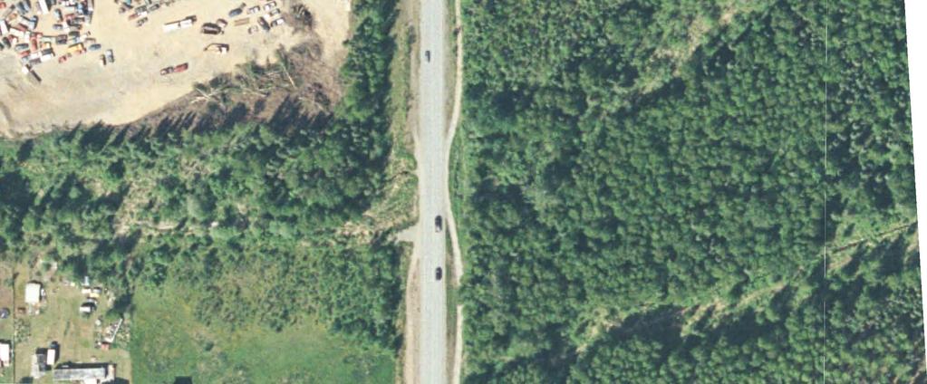
3 Geotechnical Report Museum Drive Extension Matanuska-Susitna Borough GEOTECHNICAL REPORT PARKS HIGHWAY CONNECTIONS MUSEUM DRIVE MATANUSKA-SUSTINA BOROUGH ALASKA 1.0 INTRODUCTION This report presents the results of subsurface explorations and laboratory testing for the proposed Parks Highway Connections Museum Drive Project. The purpose of the field exploration and geotechnical studies was to define the soil and groundwater conditions for use in the design of the new roadway. To develop the criteria for use in design, 20 borings were advanced along the proposed alignment of the new road. Soil samples recovered from the borings were classified in the field by an experienced engineer with Hattenburg Dilley and Linnell, LLC (HDL) and returned to our laboratory for testing and verification. The project investigation was performed in general accordance with the procedures outlined in the Alaska Geotechnical Procedures Manual (ADOT&PF, 200). Included in this report are a description of the project, subsurface exploration methods and laboratory test procedures, and results of the subsurface exploration and laboratory tests. A supplemental letter titled Geotechnical Recommendations for Parks Highway Connections: Museum Drive, March 20, addresses the recommendations for design and construction for the project. The alignment description and subsurface conditions presented herein are based on our current understanding of the alignment and project as of the date of this document. Deviation from the alignment outlined within this report may require further evaluation of subsurface conditions. This report documents subsurface geotechnical conditions and provides analyses and interpretation of anticipated site conditions for the project. This report establishes a geotechnical baseline to be used in assessing the existence and scope of changed or differing site conditions. This report is intended for use by the project design engineering staff, construction personnel, bidders, and contractors. 2.0 SITE AND PROJECT DESCRIPTION This project covers the development of an approximately 1.-mile section of roadway connecting the existing Museum Drive to the east and Sylvan Road to the west, within the Matanuska-Susitna Borough. The location of the project is shown on the vicinity map in Figure 1. It is planned that this new connection, running roughly parallel to the Page 1
4 Geotechnical Report Museum Drive Extension Matanuska-Susitna Borough Parks Highway, will provide alternate routes for local access. The new road is classified as a collector connection. The purpose of this road extension project is to improve the collector connections within the local roads west of Wasilla as growth in this area continues. It has been estimated that development of connectors like this one will enhance local traffic mobility and safety. This connector will also reduce the vehicle-miles traveled and left turn movements onto the Parks Highway. The proposed road alignment will likely cross one stream at two locations located east of Vine Road. There is also a peat bog region at the eastern end of the alignment at the future connection with Museum Drive. These features are identified on the plan and profile sheets along with the boring locations on Figures 2 through. 3.0 LOCAL CONDITIONS 3.1 General Geology The project area is located within the Cook Inlet-Susitna Lowland Section of the Coastal Trough physiographic province of Alaska. The Talkeetna Mountains border the province on the east and the Alaska Range lies to the north and west. To the south is Cook Inlet. Glacial features including ground moraines, drumlins, eskers, and outwash plains characterize the entire Cook Inlet-Susitna Lowlands. Kame and kettle topography, indicative of glacial outwash plains, is common and forms many of the hills and small rounded lakes that exist in the project area. Five major glacial advances of the Quaternary Period can be recognized throughout the vicinity ending approximately,000 years ago. Sediments are typically glacial derived sands and gravels with varying fines contents. Peat bogs have developed in many of the low-lying areas subsequent to the last glaciation. As the glaciers receded towards the mountains, the Susitna River drainage was established as well as the drainages in the project area. These drainages deposited sands and gravels in channel areas and fine grain sediment in floodplains. 3.2 Seismicity The project is located in an area of moderate seismicity. Large-scale earthquakes may cause ground ruptures along the roadway. Locations of potential rupture zones are outside the scope of this study and are extremely difficult to predict. Slopes and structures such as bridges and culverts along the road should be designed to accommodate large-scale earthquakes. Based on Alaska Earthquake Information Database there were 3 events above magnitude in the region from 1 to 200. There were events above a magnitude of which were magnitude to.. The Page 2
5 Geotechnical Report Museum Drive Extension Matanuska-Susitna Borough 200 International Building Code places the area in Site Class D based on general soil properties encountered along the alignment. 3.3 Climatology The project area is located in a transitional climatic zone varying between continental and maritime climates. The zone is characterized by pronounced diurnal and annual temperature variations, moderate annual precipitation, and moderate surface winds. Average January temperatures in the area range between 2ºF and 1ºF, while average July temperatures range between ºF and ºF. The area experiences an average of 0 wet days per year in which 0.1 inch or more of precipitation accumulates. The Environmental Atlas of Alaska provided the information for the project area. Following are mean annual values for the area: Mean Annual Temperature 30ºF Mean Annual Precipitation 2 in. Mean Annual Snowfall 0 in. Thawing Index 3000 degree days Freezing Index 300 degree says.0 FIELD STUDY The geotechnical field study consisted of soil borings and peat probing. The intent of the field study was to determine the soil properties of the existing soils along the alignment. In all, 20 soil borings were each advanced to a depth of. feet below the existing ground surface. Locations of the 20 borings are detailed on Plan and Profile sheets located in Figures 2 through. The boring locations were typically spaced at 00-foot intervals along the proposed alignment. The borings for this study were advanced between August 3 and August, 200. One-inch diameter slotted PVC pipe was installed in select borings for monitoring groundwater levels along the alignment. The water levels in these borings were measured August 2, 200, approximately 20 days after drilling was completed, which allowed for seasonal static water levels to become stabilized. Discovery Drilling Inc. of Anchorage, Alaska provided drilling services for this project using a CME mounted on a Nodwell track vehicle. The borings were advanced with 3¼-inch inside diameter (I.D.) hollow stem auger. In each of the borings, split-spoon samples were collected at typically 2. feet, feet, and -foot intervals thereafter. Sampling with the split-spoon was conducted using the Modified Penetration Test procedure. In the Modified Penetration Test, samples are recovered by driving a 3-inch O.D. split-spoon sampler into the bottom of the advancing hole with blows of a 30-lb. hammer free-falling 30 inches onto the drill rod. The number of blows required to advance the sampler the final inches of an 1-inch penetration in the test is termed Page 3
6 Geotechnical Report Museum Drive Extension Matanuska-Susitna Borough the Penetration Resistance, which was recorded for each sample depth. The values give a measure of the relative density (compactness) or consistency (stiffness) of cohesionless or cohesive soils, respectively. An experienced engineer from HDL was present continuously during drilling to locate the borings, observe drilling action, collect samples, log subsurface conditions, monitor groundwater encountered, and observe installation of groundwater monitoring equipment. The soils were classified in the field according to the Unified Soil Classification System (USCS) presented in Appendix A, Figure A1 and later verified by laboratory tests. A modified version of the U.S. Army Corps of Engineering Frost Design Soil Classification, presented in Appendix A, Figure A2, was used to estimate the frost characteristics of the soils based on the laboratory results. Detailed logs of the borings are presented on the plan and profile sheets in Figures 2 through and in Appendix A, Figures A3 through A22. Peat probing was also performed during this geotechnical field study. The probing consisted of pushing a thin steel rod with T-handle into the regions along the alignment where peat deposits were apparent. The probe was pushed until the rod tip met refusal on firm underlying materials. The depth of probe penetration was measured and recorded. A peat depth contour map presented in Figure, was created for areas where peat deposits were measured..0 LABORATORY TESTING Laboratory tests were performed on select samples recovered from the borings to verify field classifications and to determine the pertinent soil properties and behavior characteristics of the typical materials encountered along the alignment. Testing was conducted by HDL s AASHTO certified soils laboratory. The laboratory testing was formulated with an emphasis on determining the materials classification, moisture content, and frost characteristics. The soils were classified in the field and later confirmed by laboratory testing. A total of 2 moisture content tests were performed on samples from the 20 borings. These tests were conducted in accordance with procedures described in ASTM D-22. The results of the moisture content measurements are presented on the boring logs presented in Appendix A, Figures A3 through A22. Grain size classification tests for this project consisted of 20 mechanical sieve tests and eleven P200 tests. The results were used to verify material classification, estimate permeability characteristics, and determine frost susceptibility of the soils. The mechanical sieve tests were conducted according to procedures described in ASTM D- 22. The P200 tests were conducted according to procedures described in ASTM D- Page
7 Geotechnical Report Museum Drive Extension Matanuska-Susitna Borough. The results of the mechanical sieves and P200 tests are presented on the boring logs presented in Appendix A, Figures A3 through A22. The grain size curves are presented in Appendix A, Figures A23 through A2..0 SUBSURFACE CONDITIONS The subsurface conditions along the alignment are depicted on the plan and profile sheets in Figures 2 through and on the boring logs presented in Appendix A, Figures A3 through A22. The soils encountered were typically sands and gravels with varying amounts of fines. Peat deposits were found at the eastern portion of the alignment, adjacent to the existing Museum Drive, in the wetlands area..1 Groundwater and Surface Water Groundwater was encountered in some borings near stream crossings, wetlands, and other areas that had perched water tables. The groundwater was found to be shallow enough to potentially affect the roadway embankment at two sections of the alignment Station 3+00 to Station 2+00 and Station +00 to Station +00. Groundwater was not found at shallow enough depth to potentially affect the roadway embankment along the rest of the project alignment. Slotted one-inch diameter PVC pipe was installed in of the 20 borings. Groundwater levels were measured in these ten locations approximately 20 days after installation to allow for groundwater stabilization. Free water was observed in 3 of the borings during the time of drilling. Table.1 shows the measured groundwater depths in select borings during drilling and 20 days following drilling. Table.1 Measured Groundwater Levels Boring Number Depth to Groundwater (ft) During Drilling 20 Days After Drilling B- Not Observed.0 B- No PVC Installed B-. B-20. Surface water was observed in two sections along the alignment. There was a small stream encountered on the east and west sides of Vine Road between Station 1+00 and Station Also, surface water was observed the eastern end of the alignment at Museum Drive, the area where peat probing was performed..2 Soils The following discussions of the geotechnical conditions for the project are organized into segments based on subsurface similarities along the alignment. Section.2.1 Page
8 Geotechnical Report Museum Drive Extension Matanuska-Susitna Borough discusses the soils encountered in Borings B-1 through B- between the west end of the alignment at Sylvan Road and 0 feet west of Vine Road (Station +00 to +00). Vine Road is at approximately Station Section.2.2 discusses the soils encountered in Borings B- through B-, east of Vine Road (Station +00 to 1+0). Section.2.3 discusses the soils encountered in Borings B- through B-20, 1,0 feet east of Vine Road to 00 feet east of Museum Drive (Station 1+0 to +00). Section.2. discusses the peat probing results obtained from the roadway alignment section between Boring B-20 and Museum Drive (Station +00 to +00). The majority of the project will consist of fill to bring the road to finished grade. A slight cut occurs from Station +00 to Borings B-1 Through B- (Station +00 to +00) The soils encountered in Borings B-1 through B- (Figures 2 through and A3 through A), between Sylvan Drive and Vine Road, are relatively similar in soil composition. There is a vegetative mat consisting of organics with tree roots in the upper 0. to 1. feet of the borings. The soils typically consist of poorly graded and well graded sandy gravel. These soils contain fine grained soils (passing the #200 sieve) ranging between 2. to. percent and are considered slightly to non-frost susceptible, or F1 to NFS (Figure A2). The moisture contents range from 1. to. percent. The relative density of these coarse grained soils is generally medium dense to very dense. Rock fragments at the tip of the split-spoon sampler indicate that cobbles greater than 3 inches were encountered. Two of the borings, B- and B-, encountered sandy silt below the vegetative mat. In Boring B- the silt layer was found to be approximately. feet in thickness, to a depth of feet below the vegetative mat. Boring B- encountered a 2-foot layer of sandy silt terminating at a depth of approximately 2. feet below existing ground. These finegrained soils are soft and should be considered highly frost susceptible, or F frost classification. The sandy silt in Boring B- had over 3 percent passing the #200 sieve and had an in-situ moisture content of 3 percent. These localized sandy silt deposits, where encountered, will cause pavement distress by frost heaving. Groundwater was not encountered in any of these borings advanced during the drilling process or when monitoring well water levels were measured after drilling..2.2 Borings B- Through B- (Station +00 to 1+0) This section of the alignment includes the three borings directly east of Vine Road. Borings B- through B- (Figures,, and A through A) have been grouped because of their topographic, groundwater, and surface water setting, identified on Figures and. There is a small stream that flows across and adjacent to the proposed alignment. Groundwater was encountered in Borings B- and B- during drilling. As seen in Table.1, groundwater levels were found to be. feet below existing ground and deeper. The measured groundwater levels may vary seasonally. Page
9 Geotechnical Report Museum Drive Extension Matanuska-Susitna Borough The soils encountered in each of the borings were covered by a vegetative mat at the surface. Sandy silt was encountered in Borings B- and B- to approximately 3 feet below ground and should be considered highly frost susceptible. Below the sandy silt, gravelly sand and sandy gravel was encountered. Boring B- soils consisted of gravelly sand to sandy gravel and did not encounter sandy silt to the depths of the boring. The coarse-grained soils encountered are considered to be non-frost susceptible or NFS, due to the fines contents of less than percent. These soils were found to have relative densities ranging between dense to very dense..2.3 Borings B- Through B-20 (Station 1+0 to +00) Along the alignment, after Boring B-, there is a significant rise in the ground surface topography, east of the small stream. Boring B- was advanced at the top edge of that slope. The soils encountered from Boring B- through B-20 (Figures through and A through A22) were found to be similar. These borings encountered a -inch thick vegetative mat of organics and tree roots. The soils consisted primarily of silty, gravelly sand to silty, sandy gravel with fines contents ranging from. to 32.2 percent. These soils are considered to be moderately frost susceptible and are classified as F2 and F3 soils. Rock fragments at the tip of the split-spoon sampler indicate that cobbles greater than 3 inches were encountered within the soil matrix. Moisture contents of these soils range from.0 to. percent. The relative densities of these soils range from medium dense to very dense. A layer of sandy silt was encountered just below the vegetative mat in Borings B-, B- 1, and B-20 with thicknesses of. feet, 2 feet, and 2 feet, respectively. These fine grained soils ranged from loose near the surface to very hard with depth. The sandy silt, as discussed previously, is considered highly frost susceptible, or classified as an F soil. Groundwater was encountered in Boring B-20. A 1-inch slotted PVC pipe was installed in this boring and ground water levels were measured to be approximately. feet below the ground surface..2. Peat Deposits (Station +00 to +00) Between Boring B-20 and Museum Drive, surface water and a significant peat deposit were observed. Peat probing was performed in order to develop a contour map of the approximate peat thickness and is presented in Figure. Peat thickness in this area ranges from less than inches to greater than 0 inches within the proposed roadway alignment right-of-way. There is an open body of water located to the south of this alignment. No other peat deposits were observed along the Museum Drive Extension Project alignment. Page
10
11

12

13


14

15
16

17

18


19


20


21
22 APPENDIX A Figure A1 Figure A2 Figure A3-A22 Figure A23-A2 Unified Soil Classification Frost Classification Boring Logs Grain Size Curves
23
24
25 LOG OF TEST HOLE PROJECT NUMBER : 0-0 PROJECT : Parks Highway Connections: Museum Drive CLIENT : Matanuska-Susitna Borough HOLE # B- 1 Station / Location: Offset: Elevation: Depth (Feet) 0 1 Sample Type Sample Data Number Blow Count Sample Recovery N-Value USCS Classification GP Frozen Zone Soil Graphic Depth in (ft.) Time Date Symbol Equipment_Type: CME Nodwell Drilling Method: Hollow-Stem Auger Field Crew: Discovery Drilling Ground Water Data /3/0 /2/0 SUBSURFACE MATERIAL Topsoil brown, moist, Vegetative mat sandy GRAVEL (GP) poorly graded, grayish brown, dry to moist, dense Total Depth:.0 feet Date: /3/200 - /3/200 Geologist: J. Thornley; HDL Engineering S " rock at sampler tip P200-3.% (NFS) S1 Moisture =2.0% 2.0 S2 1 (NFS) S2 P200 =.%, Sa =3.%, Gr =.%, Moisture =2.1%.00 A USCS LOG OF TEST HOLE 0-0_MUSEUM_DRIVE.GPJ 200DATATEMPLATE.GDT /2/0 S S3 CME Auto Hammer Cathead Rope Method BOH. 0 lb. hammer with 30 in. drop 30 lb. hammer with 30 in. drop.0 Sheet Number 1 of 1 Figure A3
26 LOG OF TEST HOLE PROJECT NUMBER : 0-0 PROJECT : Parks Highway Connections: Museum Drive CLIENT : Matanuska-Susitna Borough HOLE # B- 2 Station / Location: Offset: Elevation: Depth (Feet) 0 1 Sample Type Sample Data Number Blow Count Sample Recovery N-Value USCS Classification GW Frozen Zone Soil Graphic Depth in (ft.) Time Date Symbol Equipment_Type: CME Nodwell Drilling Method: Hollow-Stem Auger Field Crew: Discovery Drilling Ground Water Data /3/0 /2/0 SUBSURFACE MATERIAL Topsoil brown, moist, Vegetative mat sandy GRAVEL (GW) well graded, grayish brown, dry to moist, medium dense Total Depth:.0 feet Date: /3/200 - /3/200 Geologist: J. Thornley; HDL Engineering S1 2." fractured rock in sampler tip (NFS) S1 P200 =2.%, Sa =31.3%, Gr =.2%, Moisture =2.2% 2.0 S2 1 sandy GRAVEL grayish brown, dry to moist, dense S2 Moisture =2.%.00 A USCS LOG OF TEST HOLE 0-0_MUSEUM_DRIVE.GPJ 200DATATEMPLATE.GDT /2/0 S S3 CME Auto Hammer Cathead Rope Method BOH. 2" fractured rocks in sampler S3 Moisture =3.% Fractured rocks in sampler Notes: Slotted PVC pipe installed, no free water encountered 0 lb. hammer with 30 in. drop 30 lb. hammer with 30 in. drop Sheet Number 1 of 1 Figure A
27 LOG OF TEST HOLE PROJECT NUMBER : 0-0 PROJECT : Parks Highway Connections: Museum Drive CLIENT : Matanuska-Susitna Borough HOLE # B- 3 Station / Location: Offset: Elevation: Depth (Feet) 0 1 Sample Type Sample Data Number Blow Count Sample Recovery N-Value USCS Classification GP Frozen Zone Soil Graphic Depth in (ft.) Time Date Symbol Equipment_Type: CME Nodwell Drilling Method: Hollow-Stem Auger Field Crew: Discovery Drilling Ground Water Data /3/0 /2/0 SUBSURFACE MATERIAL Topsoil brown, moist, Vegetative mat Total Depth:.0 feet Date: /3/200 - /3/200 Geologist: J. Thornley; HDL Engineering sandy GRAVEL (GP) poorly graded, grayish brown, dry to moist, medium dense S1 2" fractured rock in sampler tip 2.0 S (NFS) S2 P200 =.%, Sa =3.1%, Gr =0.%, Moisture =2.%.00 A USCS LOG OF TEST HOLE 0-0_MUSEUM_DRIVE.GPJ 200DATATEMPLATE.GDT /2/0 S S3 CME Auto Hammer Cathead Rope Method BOH. S Moisture =.% 0 lb. hammer with 30 in. drop 30 lb. hammer with 30 in. drop.0 Sheet Number 1 of 1 Figure A
28 LOG OF TEST HOLE PROJECT NUMBER : 0-0 PROJECT : Parks Highway Connections: Museum Drive CLIENT : Matanuska-Susitna Borough HOLE # B- Station / Location: Offset: Elevation: Equipment_Type: CME Nodwell Total Depth:.0 feet Drilling Method: Hollow-Stem Auger Date: /3/200 - /3/200 Field Crew: Discovery Drilling Geologist: J. Thornley; HDL Engineering Sample Data Ground Water Data Depth (Feet) 0 Sample Type Number Blow Count Sample Recovery N-Value USCS Classification Frozen Zone Soil Graphic Depth in (ft.) Time Date /3/0 /2/0 Symbol SUBSURFACE MATERIAL Topsoil brown, moist, Vegetative mat ML sandy SILT (ML) brown, moist, soft S1 2 2 P % (F) S1 Moisture =3.1% S2 2 GP-GM slightly silty, sandy GRAVEL (GP-GM) gray, dry to moist, medium dense, 2" fractured rock in sampler.00 A USCS LOG OF TEST HOLE 0-0_MUSEUM_DRIVE.GPJ 200DATATEMPLATE.GDT /2/0 S S3 CME Auto Hammer Cathead Rope Method BOH. (F1) S3 P200 =.3%, Sa =0.%, Gr =2.%, Moisture =.2% Notes: Slotted PVC pipe installed, no free water encountered 0 lb. hammer with 30 in. drop 30 lb. hammer with 30 in. drop.00.0 Sheet Number 1 of 1 Figure A
29 LOG OF TEST HOLE PROJECT NUMBER : 0-0 PROJECT : Parks Highway Connections: Museum Drive CLIENT : Matanuska-Susitna Borough HOLE # B- Station / Location: Offset: Elevation: Depth (Feet) 0 1 Sample Type Sample Data Number Blow Count Sample Recovery N-Value USCS Classification Frozen Zone Soil Graphic Depth in (ft.) Time Date Symbol Equipment_Type: CME Nodwell Total Depth:.0 feet Drilling Method: Hollow-Stem Auger Date: /3/200 - /3/200 Field Crew: Discovery Drilling Geologist: J. Thornley; HDL Engineering Ground Water Data /3/0 /2/0 SUBSURFACE MATERIAL Topsoil brown, moist, Vegetative mat sandy GRAVEL grayish brown, dry to moist, medium dense S1 2" fractured rock at sampler tip S1 Moisture =2.3% 2.0 S2 1 2 GW sandy GRAVEL (GW) well graded, grayish brown, dry to moist, dense, (NFS) 2" fractured rock at sampler tip S2 P200 =.%, Sa =3.1%, Gr =.%, Moisture =2.0%.00 A USCS LOG OF TEST HOLE 0-0_MUSEUM_DRIVE.GPJ 200DATATEMPLATE.GDT /2/0 S S3 CME Auto Hammer Cathead Rope Method BOH. 2" fractured rock at sampler tip S3 Moisture =2.3% Notes: Slotted PVC pipe installed, no free water encountered 0 lb. hammer with 30 in. drop 30 lb. hammer with 30 in. drop.00.0 Sheet Number 1 of 1 Figure A
30 LOG OF TEST HOLE PROJECT NUMBER : 0-0 PROJECT : Parks Highway Connections: Museum Drive CLIENT : Matanuska-Susitna Borough HOLE # B- Station / Location: Offset: Elevation: Depth (Feet) 0 1 Sample Type Sample Data Number Blow Count Sample Recovery N-Value USCS Classification Frozen Zone Soil Graphic Depth in (ft.) Time Date Symbol Equipment_Type: CME Nodwell Total Depth:.0 feet Drilling Method: Hollow-Stem Auger Date: /3/200 - /3/200 Field Crew: Discovery Drilling Geologist: J. Thornley; HDL Engineering Ground Water Data /3/0 /2/0 SUBSURFACE MATERIAL Topsoil brown, moist, Vegetative mat sandy GRAVEL grayish brown, dry to moist, very dense S1 1 2" fractured rock at sampler tip S S2 Moisture =2.% A USCS LOG OF TEST HOLE 0-0_MUSEUM_DRIVE.GPJ 200DATATEMPLATE.GDT /2/0 S S3 CME Auto Hammer 2 1 SP-SM Cathead Rope Method BOH. slightly silty, gravelly SAND (SP-SM) poorly graded, grayish brown, dry to moist, very dense (F2) S P200 =.%, Sa =.%, Gr =.%, Moisture =3.% 0 lb. hammer with 30 in. drop 30 lb. hammer with 30 in. drop Sheet Number 1 of 1 Figure A
31 LOG OF TEST HOLE PROJECT NUMBER : 0-0 PROJECT : Parks Highway Connections: Museum Drive CLIENT : Matanuska-Susitna Borough HOLE # B- Station / Location: Offset: Elevation: Depth (Feet) 0 1 Sample Type Sample Data Number Blow Count Sample Recovery N-Value USCS Classification Frozen Zone Soil Graphic Depth in (ft.) Time Date Symbol Equipment_Type: CME Nodwell Total Depth:.0 feet Drilling Method: Hollow-Stem Auger Date: //200 - //200 Field Crew: Discovery Drilling Geologist: J. Thornley; HDL Engineering Ground Water Data //0 /2/0 SUBSURFACE MATERIAL Topsoil brown, moist, Vegetative mat sandy GRAVEL brown, dry to moist, very dense S1 20 P % (NFS) S1 Moisture =2.% 2.0 S2 S2 Moisture =2.% A USCS LOG OF TEST HOLE 0-0_MUSEUM_DRIVE.GPJ 200DATATEMPLATE.GDT /2/0 S S3 CME Auto Hammer GW Cathead Rope Method BOH. sandy GRAVEL (GW) well graded, brown, moist, dense, (NFS) 2." fractured rock at sampler tip S3 P200 =.0%, Sa =31.%, Gr =.1%, Moisture =1.% Notes: Slotted PVC pipe installed, no free water encountered 0 lb. hammer with 30 in. drop lb. hammer with 30 in. drop Sheet Number 1 of 1 Figure A
32 LOG OF TEST HOLE PROJECT NUMBER : 0-0 PROJECT : Parks Highway Connections: Museum Drive CLIENT : Matanuska-Susitna Borough HOLE # B- Station / Location: Offset: Elevation: Depth (Feet) 0 1 Sample Type Sample Data Number Blow Count Sample Recovery N-Value USCS Classification Frozen Zone Soil Graphic Depth in (ft.) Time Date Symbol Equipment_Type: CME Nodwell Drilling Method: Hollow-Stem Auger Field Crew: Discovery Drilling Ground Water Data //0 sandy SILT brown, moist /2/0 SUBSURFACE MATERIAL Topsoil brown, moist, Vegetative mat Total Depth:.0 feet Date: //200 - //200 Geologist: J. Thornley; HDL Engineering S1 sandy GRAVEL brown, moist, dense S1 Moisture =2.% S2 1 0 P200 -.% (F1) S2 Moisture =2.%.00 A USCS LOG OF TEST HOLE 0-0_MUSEUM_DRIVE.GPJ 200DATATEMPLATE.GDT /2/0 S S3 CME Auto Hammer Cathead Rope Method BOH. 0 lb. hammer with 30 in. drop 30 lb. hammer with 30 in. drop.0 Sheet Number 1 of 1 Figure A
33 LOG OF TEST HOLE PROJECT NUMBER : 0-0 PROJECT : Parks Highway Connections: Museum Drive CLIENT : Matanuska-Susitna Borough HOLE # B- Station / Location: Offset: Elevation: Depth (Feet) 0 1 Sample Type Sample Data Number Blow Count Sample Recovery N-Value USCS Classification GW Frozen Zone Soil Graphic Depth in (ft.) Time Date Symbol Equipment_Type: CME Nodwell Drilling Method: Hollow-Stem Auger Field Crew: Discovery Drilling Ground Water Data //0 /2/0 SUBSURFACE MATERIAL Topsoil brown, moist, Vegetative mat sandy GRAVEL (GW) well graded, brown, moist, dense Total Depth:.0 feet Date: //200 - //200 Geologist: J. Thornley; HDL Engineering S2 S (NFS) S1 P200 =3.%, Sa =3.%, Gr =.%, Moisture =2.% P200-2.% (NFS) S2 Moisture =2.% A USCS LOG OF TEST HOLE 0-0_MUSEUM_DRIVE.GPJ 200DATATEMPLATE.GDT /2/0 S S3 CME Auto Hammer GP Cathead Rope Method BOH. sandy GRAVEL (GP) poorly graded, brown, moist, dense S3 Moisture =2.% (NFS) S P200 =.3%, Sa =3.%, Gr =.%, Moisture =3.% Notes: Slotted PVC pipe installed, no free water encountered 0 lb. hammer with 30 in. drop 30 lb. hammer with 30 in. drop Sheet Number 1 of 1 Figure A
34 LOG OF TEST HOLE PROJECT NUMBER : 0-0 PROJECT : Parks Highway Connections: Museum Drive CLIENT : Matanuska-Susitna Borough HOLE # B- Station / Location: Offset: Elevation: Depth (Feet) 0 1 Sample Type Sample Data Number Blow Count Sample Recovery N-Value USCS Classification Frozen Zone Soil Graphic Equipment_Type: CME Nodwell Total Depth:.0 feet Drilling Method: Hollow-Stem Auger Date: //200 - //200 Field Crew: Discovery Drilling Geologist: J. Thornley; HDL Engineering Ground Water Data Depth in (ft.).0 Time Date //0 /2/0 Symbol SUBSURFACE MATERIAL Topsoil brown, moist, Vegetative mat 0.00 sandy SILT brown, moist A USCS LOG OF TEST HOLE 0-0_MUSEUM_DRIVE.GPJ 200DATATEMPLATE.GDT /2/0 3 S S3 S2 S1 CME Auto Hammer SP Cathead Rope Method BOH. gravelly SAND (SP) poorly graded, brown, moist, dense (NFS) S2 P200 =2.%, Sa =3.0%, Gr =.%, Moisture =2.% sandy GRAVEL brown, moist, very dense S3 Moisture =2.% P % (NFS) S Moisture =3.% Notes: Slotted PVC pipe installed 0 lb. hammer with 30 in. drop 30 lb. hammer with 30 in. drop Sheet Number 1 of 1 Figure A
35 LOG OF TEST HOLE PROJECT NUMBER : 0-0 PROJECT : Parks Highway Connections: Museum Drive CLIENT : Matanuska-Susitna Borough HOLE # B- Station / Location: Offset: Elevation: Depth (Feet) 0 1 Sample Type Sample Data Number Blow Count Sample Recovery N-Value USCS Classification Frozen Zone SP-SM Soil Graphic Depth in (ft.) Time Date Symbol Equipment_Type: CME Nodwell Drilling Method: Hollow-Stem Auger Field Crew: Discovery Drilling Ground Water Data //0 /2/0 SUBSURFACE MATERIAL Topsoil brown, moist, Vegetative mat slightly silty, gravelly SAND (SP-SM) brown, moist, very dense Total Depth:.0 feet Date: //200 - //200 Geologist: J. Thornley; HDL Engineering S1 2 P200 -.% (NFS) S1 Moisture =3.3% S (NFS) S2 P200 =.3%, Sa =.1%, Gr =3.%, Moisture =2.%.00 A USCS LOG OF TEST HOLE 0-0_MUSEUM_DRIVE.GPJ 200DATATEMPLATE.GDT /2/0 S S3 CME Auto Hammer 1 2 Cathead Rope Method BOH. sandy GRAVEL brown, moist to wet, dense S3 Moisture =3.2% 0 lb. hammer with 30 in. drop 30 lb. hammer with 30 in. drop.00.0 Sheet Number 1 of 1 Figure A
36 LOG OF TEST HOLE PROJECT NUMBER : 0-0 PROJECT : Parks Highway Connections: Museum Drive CLIENT : Matanuska-Susitna Borough HOLE # B- Station / Location: Offset: Elevation: Depth (Feet) 0 1 Sample Type Sample Data Number Blow Count Sample Recovery N-Value USCS Classification Frozen Zone Soil Graphic Depth in (ft.) Time Date Symbol Equipment_Type: CME Nodwell Drilling Method: Hollow-Stem Auger Field Crew: Discovery Drilling Ground Water Data //0 sandy SILT brown, moist.1 /2/0 SUBSURFACE MATERIAL Topsoil brown, moist, Vegetative mat Total Depth:.0 feet Date: //200 - //200 Geologist: J. Thornley; HDL Engineering S1 GW S1 Moisture =3.1% sandy GRAVEL (GW) well graded, brown, moist to wet, medium dense to dense 3.00 S2 1 S2 Moisture =3.1% A USCS LOG OF TEST HOLE 0-0_MUSEUM_DRIVE.GPJ 200DATATEMPLATE.GDT /2/0 S S3 CME Auto Hammer 1 Cathead Rope Method BOH. (NFS) S3 P200 =.2%, Sa =3.1%, Gr =.%, Moisture =.1% Notes: Slotted PVC pipe installed 0 lb. hammer with 30 in. drop 30 lb. hammer with 30 in. drop.00.0 Sheet Number 1 of 1 Figure A
37 LOG OF TEST HOLE PROJECT NUMBER : 0-0 PROJECT : Parks Highway Connections: Museum Drive CLIENT : Matanuska-Susitna Borough HOLE # B- Station / Location: Offset: Elevation: Depth (Feet) 0 1 Sample Type Sample Data Number Blow Count Sample Recovery N-Value USCS Classification SM Frozen Zone Soil Graphic Depth in (ft.) Time Date Symbol Equipment_Type: CME Nodwell Total Depth:.0 feet Drilling Method: Hollow-Stem Auger Date: //200 - //200 Field Crew: Discovery Drilling Geologist: J. Thornley; HDL Engineering Ground Water Data //0 /2/0 SUBSURFACE MATERIAL Topsoil brown, moist, Vegetative mat silty, gravelly SAND (SM) brown, moist, loose S1 P200-1.% (F3) S1 Moisture =.% 2.0 S2 3 dense, (F3) S2 P200 =32.2%, Sa =3.%, Gr =30.%, Moisture =.%.00 A USCS LOG OF TEST HOLE 0-0_MUSEUM_DRIVE.GPJ 200DATATEMPLATE.GDT /2/0 S S3 CME Auto Hammer Cathead Rope Method BOH. sandy GRAVEL brown, moist, very dense 0 lb. hammer with 30 in. drop 30 lb. hammer with 30 in. drop.00.0 Sheet Number 1 of 1 Figure A
38 LOG OF TEST HOLE PROJECT NUMBER : 0-0 PROJECT : Parks Highway Connections: Museum Drive CLIENT : Matanuska-Susitna Borough HOLE # B- Station / Location: Offset: Elevation: Depth (Feet) 0 1 Sample Type Sample Data Number Blow Count Sample Recovery N-Value USCS Classification SM Frozen Zone Soil Graphic Depth in (ft.) Time Date Symbol Equipment_Type: CME Nodwell Drilling Method: Hollow-Stem Auger Field Crew: Discovery Drilling Ground Water Data //0 /2/0 SUBSURFACE MATERIAL Topsoil brown, moist, Vegetative mat silty, gravelly SAND (SM) brown, moist, medium dense Total Depth:.0 feet Date: //200 - //200 Geologist: J. Thornley; HDL Engineering S1 P % (F3) S1 Moisture =.% 2.0 S2 (F3) S2 P200 =2.2%, Sa =3.%, Gr =3.3%, Moisture =.%.00 A USCS LOG OF TEST HOLE 0-0_MUSEUM_DRIVE.GPJ 200DATATEMPLATE.GDT /2/0 S S3 CME Auto Hammer Cathead Rope Method BOH. S3 Moisture =.% 0 lb. hammer with 30 in. drop 30 lb. hammer with 30 in. drop.0 Sheet Number 1 of 1 Figure A
39 LOG OF TEST HOLE PROJECT NUMBER : 0-0 PROJECT : Parks Highway Connections: Museum Drive CLIENT : Matanuska-Susitna Borough HOLE # B- Station / Location: Offset: Elevation: Depth (Feet) 0 1 Sample Type Sample Data Number Blow Count Sample Recovery N-Value USCS Classification SM Frozen Zone Soil Graphic Depth in (ft.) Time Date Symbol Equipment_Type: CME Nodwell Drilling Method: Hollow-Stem Auger Field Crew: Discovery Drilling Ground Water Data //0 /2/0 SUBSURFACE MATERIAL Topsoil brown, moist, Vegetative mat silty, gravelly SAND (SM) brown, moist, medium dense to dense Total Depth:.0 feet Date: //200 - //200 Geologist: J. Thornley; HDL Engineering S1 3 (F3) S1 P200 =1.%, Sa =.2%, Gr =31.0%, Moisture =.% 2.0 S2 1 3" fractured rock at sampler tip S2 Moisture =.2%.00 A USCS LOG OF TEST HOLE 0-0_MUSEUM_DRIVE.GPJ 200DATATEMPLATE.GDT /2/0 S S3 CME Auto Hammer Cathead Rope Method BOH. S Moisture =.0% Notes: Slotted PVC pipe installed, no free water encountered 0 lb. hammer with 30 in. drop 30 lb. hammer with 30 in. drop.0 Sheet Number 1 of 1 Figure A1
40 LOG OF TEST HOLE PROJECT NUMBER : 0-0 PROJECT : Parks Highway Connections: Museum Drive CLIENT : Matanuska-Susitna Borough HOLE # B- Station / Location: Offset: Elevation: Depth (Feet) 0 1 Sample Type Sample Data Number Blow Count Sample Recovery N-Value USCS Classification Frozen Zone Soil Graphic Depth in (ft.) Time Date Symbol Equipment_Type: CME Nodwell Total Depth:.0 feet Drilling Method: Hollow-Stem Auger Date: //200 - //200 Field Crew: Discovery Drilling Geologist: J. Thornley; HDL Engineering Ground Water Data //0 /2/0 SUBSURFACE MATERIAL Topsoil brown, moist, Vegetative mat sandy SILT brown, moist, very hard S SM silty, gravelly SAND (SM) brown, moist, dense.00 S2 1 3 A USCS LOG OF TEST HOLE 0-0_MUSEUM_DRIVE.GPJ 200DATATEMPLATE.GDT /2/0 S S3 CME Auto Hammer 0 21 Cathead Rope Method BOH. S3 Moisture =.3% (F2) S P200 =.%, Sa =3.%, Gr =33.%, Moisture =.0% 0 lb. hammer with 30 in. drop 30 lb. hammer with 30 in. drop.00.0 Sheet Number 1 of 1 Figure A1
41 LOG OF TEST HOLE PROJECT NUMBER : 0-0 PROJECT : Parks Highway Connections: Museum Drive CLIENT : Matanuska-Susitna Borough HOLE # B-1 Station / Location: Offset: Elevation: Depth (Feet) 0 1 Sample Type Sample Data Number Blow Count Sample Recovery N-Value USCS Classification Frozen Zone Soil Graphic Depth in (ft.) Time Date Symbol Equipment_Type: CME Nodwell Total Depth:.0 feet Drilling Method: Hollow-Stem Auger Date: //200 - //200 Field Crew: Discovery Drilling Geologist: J. Thornley; HDL Engineering Ground Water Data //0 SUBSURFACE MATERIAL Topsoil brown, moist, Vegetative mat sandy SILT brown, moist /2/ S1 SM silty, gravelly SAND (SM) brown, moist, medium dense to dense 2.0 S2 P200-2.% (F3) S2 Moisture =.2%.00 A USCS LOG OF TEST HOLE 0-0_MUSEUM_DRIVE.GPJ 200DATATEMPLATE.GDT /2/0 S S3 CME Auto Hammer 1 2 Cathead Rope Method BOH. (F3) S3 P200 =2.0%, Sa =3.%, Gr =3.%, Moisture =.% Notes: Slotted PVC pipe installed, no free water encountered 0 lb. hammer with 30 in. drop 30 lb. hammer with 30 in. drop.00.0 Sheet Number 1 of 1 Figure A1
42 LOG OF TEST HOLE PROJECT NUMBER : 0-0 PROJECT : Parks Highway Connections: Museum Drive CLIENT : Matanuska-Susitna Borough HOLE # B-1 Station / Location: Offset: Elevation: Depth (Feet) 0 1 Sample Type Sample Data Number Blow Count Sample Recovery N-Value USCS Classification SM Frozen Zone Soil Graphic Depth in (ft.) Time Date Symbol Equipment_Type: CME Nodwell Drilling Method: Hollow-Stem Auger Field Crew: Discovery Drilling Ground Water Data //0 /2/0 SUBSURFACE MATERIAL Topsoil brown, moist, Vegetative mat silty, gravelly SAND (SM) brown, dry to moist, medium dense to dense Total Depth:.0 feet Date: //200 - //200 Geologist: J. Thornley; HDL Engineering S1 S1 No sample recovered 1 S2 2 (F3) 2." fractured rock at sampler tip S2 P200 =2.%, Sa =2.1%, Gr =30.3%, Moisture =.%.00 A USCS LOG OF TEST HOLE 0-0_MUSEUM_DRIVE.GPJ 200DATATEMPLATE.GDT /2/0 S S3 CME Auto Hammer Cathead Rope Method BOH. S3 Moisture =.% S Moisture =.% 0 lb. hammer with 30 in. drop 30 lb. hammer with 30 in. drop.0 Sheet Number 1 of 1 Figure A20
43 LOG OF TEST HOLE PROJECT NUMBER : 0-0 PROJECT : Parks Highway Connections: Museum Drive CLIENT : Matanuska-Susitna Borough HOLE # B-1 Station / Location: Offset: Elevation: Depth (Feet) 0 1 Sample Type Sample Data Number Blow Count Sample Recovery N-Value USCS Classification GM Frozen Zone Soil Graphic Depth in (ft.) Time Date Symbol Equipment_Type: CME Nodwell Drilling Method: Hollow-Stem Auger Field Crew: Discovery Drilling Ground Water Data //0 /2/0 SUBSURFACE MATERIAL Topsoil brown, moist, Vegetative mat silty, sandy GRAVEL (GM) brown, moist, medium dense, (F2) Total Depth:.0 feet Date: //200 - //200 Geologist: J. Thornley; HDL Engineering S1 S1 Moisture =.1% S2 S2 P200 =1.2%, Sa =3.3%, Gr =3.%, Moisture =.0% silty, gravelly SAND brown, moist, medium dense.00 A USCS LOG OF TEST HOLE 0-0_MUSEUM_DRIVE.GPJ 200DATATEMPLATE.GDT /2/0 S S3 CME Auto Hammer Cathead Rope Method BOH. 0 lb. hammer with 30 in. drop 30 lb. hammer with 30 in. drop.0 Sheet Number 1 of 1 Figure A21
44 LOG OF TEST HOLE PROJECT NUMBER : 0-0 PROJECT : Parks Highway Connections: Museum Drive CLIENT : Matanuska-Susitna Borough HOLE # B-20 Station / Location: Offset: Elevation: Depth (Feet) 0 1 Sample Type Sample Data Number Blow Count Sample Recovery N-Value USCS Classification Frozen Zone Soil Graphic Depth in (ft.) Time Date Symbol Equipment_Type: CME Nodwell Drilling Method: Hollow-Stem Auger Field Crew: Discovery Drilling Ground Water Data //0. /2/0 SUBSURFACE MATERIAL Topsoil brown, moist, Vegetative mat sandy SILT light brown, dry to moist Total Depth:.0 feet Date: //200 - //200 Geologist: J. Thornley; HDL Engineering S1 SM silty, gravelly SAND (SM) light brown, dry to moist, medium dense, P200-2.% (F3) 1." fractured rock at sampler tip S1 Moisture =.% 2.0 A USCS LOG OF TEST HOLE 0-0_MUSEUM_DRIVE.GPJ 200DATATEMPLATE.GDT /2/0 S S3 S2 2 CME Auto Hammer 0 2 Cathead Rope Method BOH. 3" fractured rock at sampler tip S2 No sample recovered (F3) S3 P200 =23.%, Sa =.1%, Gr =32.1%, Moisture =.% Notes: Slotted PVC pipe installed 0 lb. hammer with 30 in. drop 30 lb. hammer with 30 in. drop Sheet Number 1 of 1 Figure A22
45 PERCENT FINER BY WEIGHT U.S. SIEVE OPENING IN INCHES U.S. SIEVE NUMBERS / 1/ / HYDROMETER GRAIN SIZE IN MILLIMETERS COBBLES coarse GRAVEL fine coarse medium SAND fine SILT OR CLAY GRAIN SIZE 0-0_MUSEUM_DRIVE.GPJ HDEC.GDT /2/0 : Specimen Identification B- 1 B- 2 B- 3 B- 1 B- 2 B- 3 B- B- Depth.0 Depth 2. Depth.0 Depth.0 Depth.0 B- B- Specimen Identification Depth.0 Depth 2. Depth.0 Depth.0 Depth.0 Classification sandy GRAVEL (GP) sandy GRAVEL (GW) sandy GRAVEL (GP) slightly silty, sandy, GRAVEL (GP-GM) sandy GRAVEL (GW) D0 D0 D30 D Matanuska-Susitna Borough LL Cu %Gravel %Sand %Silt %Clay Parks Highway Connections: Museum Drive Alaska 0-0 PL PI Cc GRAIN SIZE DISTRIBUTION Figure A23
46 0 U.S. SIEVE OPENING IN INCHES / 1/2 3/ 3 U.S. SIEVE NUMBERS HYDROMETER PERCENT FINER BY WEIGHT GRAIN SIZE IN MILLIMETERS COBBLES coarse GRAVEL fine coarse medium SAND fine SILT OR CLAY GRAIN SIZE 0-0_MUSEUM_DRIVE.GPJ HDEC.GDT /2/0 : Specimen Identification B- B- B- B- B- B- B- B- Depth.0 Depth.0 Depth 2. Depth.0 Depth.0 B- B- Specimen Identification Depth.0 Depth.0 Depth 2. Depth.0 Depth.0 D Classification slightly silty, gravelly SAND (SP-SM) sandy GRAVEL (GW) sandy GRAVEL (GW) sandy GRAVEL (GP) gravelly SAND (SP) D0 D D Matanuska-Susitna Borough LL Cu %Gravel %Sand %Silt %Clay Parks Highway Connections: Museum Drive Alaska 0-0 PL PI Cc GRAIN SIZE DISTRIBUTION Figure A2
47 0 U.S. SIEVE OPENING IN INCHES U.S. SIEVE NUMBERS 2 1 1/ / 3/ HYDROMETER PERCENT FINER BY WEIGHT GRAIN SIZE IN MILLIMETERS COBBLES coarse GRAVEL fine coarse medium SAND fine SILT OR CLAY GRAIN SIZE 0-0_MUSEUM_DRIVE.GPJ HDEC.GDT 1/20/ :02 Specimen Identification B- Depth.0 B- Depth.0 B- Depth.0 B- Depth.0 B- Depth 2. Specimen Identification B- Depth.0 B- Depth.0 B- Depth.0 B- Depth.0 B- Depth 2. D D Classification slightly silty, gravelly SAND (SP-SM) sandy GRAVEL (GW) gravelly, silty SAND (SM) silty, gravelly SAND (SM) silty, gravelly SAND (SM) D D Matanuska-Susitna Borough %Gravel LL %Sand Cu %Silt %Clay Parks Highway Connections: Museum Drive Alaska 0-0 PL PI Cc GRAIN SIZE DISTRIBUTION Figure A2
48 PERCENT FINER BY WEIGHT U.S. SIEVE OPENING IN INCHES U.S. SIEVE NUMBERS 2 1 1/ / / HYDROMETER GRAIN SIZE IN MILLIMETERS COBBLES GRAVEL coarse fine coarse medium SAND fine SILT OR CLAY GRAIN SIZE 0-0_MUSEUM_DRIVE.GPJ HDEC.GDT /2/0 : Specimen Identification B- Depth.0 B-1 Depth.0 B-1 Depth.0 B-1 Depth.0 B-20 Depth.0 Specimen Identification B- B-1 B-1 B-1 B-20 Depth.0 Depth.0 Depth.0 Depth.0 Depth.0 D silty, gravelly SAND (SM) silty, gravelly SAND (SM) silty, gravelly SAND (SM) silty, sandy GRAVEL (GM) silty, gravelly SAND (SM) D0 D30 D Classification Matanuska-Susitna Borough Parks Highway Connections: Museum Drive Alaska %Gravel LL PL %Sand PI GRAIN SIZE DISTRIBUTION Cc Cu 1.1. %Silt %Clay Figure A2
 Project: ITHACA-TOMPKINS REGIONAL AIRPORT EXPANSION Project Location: ITHACA, NY Project Number: 218-34 Key to Soil Symbols and Terms TERMS DESCRIBING CONSISTENCY OR CONDITION COARSE-GRAINED SOILS (major
Civil Engineering, Surveying and Environmental Consulting WASP0059.ltr.JLS.Mich Ave Bridge Geotech.docx
 2365 Haggerty Road South * Canton, Michigan 48188 P: 734-397-3100 * F: 734-397-3131 * www.manniksmithgroup.com August 29, 2012 Mr. Richard Kent Washtenaw County Parks and Recreation Commission 2330 Platt
Pierce County Department of Planning and Land Services Development Engineering Section
 Page 1 of 7 Pierce County Department of Planning and Land Services Development Engineering Section PROJECT NAME: DATE: APPLICATION NO.: PCDE NO.: LANDSLIDE HAZARD AREA (LHA) GEOLOGICAL ASSESSMENT REPORT
Geotechnical Data Report
 Geotechnical Data Report Downtown Greenville Future Conveyance Study December 1, 2015 Terracon Project No. 86155032 Prepared for: Prepared by: Terracon Consultants, Inc. December 1, 2015 561 Mauldin Road
B-1 BORE LOCATION PLAN. EXHIBIT Drawn By: 115G BROOKS VETERINARY CLINIC CITY BASE LANDING AND GOLIAD ROAD SAN ANTONIO, TEXAS.
 N B-1 SYMBOLS: Exploratory Boring Location Project Mngr: BORE LOCATION PLAN Project No. GK EXHIBIT Drawn By: 115G1063.02 GK Scale: Checked By: 1045 Central Parkway North, Suite 103 San Antonio, Texas 78232
Geotechnical Data Report
 Geotechnical Data Report ReWa Solar Farm at Durbin Creek Fountain Inn, South Carolina September 1, 2017 Terracon Project No. 86165043 Prepared for: Renewable Water Resources Greenville, South Carolina
 Photo 1 - Southerly view across 2700 parking lot toward existing building. Multi-residential building borders western side of property in upper right of view. Photo 2 - Southerly view across 2750 parking
ATTACHMENT A PRELIMINARY GEOTECHNICAL SUMMARY
 ATTACHMENT A PRELIMINARY GEOTECHNICAL SUMMARY Kevin M. Martin, P.E. KMM Geotechnical Consultants, LLC 7 Marshall Road Hampstead, NH 0384 603-489-6 (p)/ 603-489-8 (f)/78-78-4084(m) kevinmartinpe@aol.com
Depth (ft) USCS Soil Description TOPSOIL & FOREST DUFF
 USCS Soil Description TOPSOIL & FOREST DUFF") Test Pit No. TP-6 Location: Latitude 47.543003, Longitude -121.980441 Approximate Ground Surface Elevation: 1,132 feet Depth (ft) USCS Soil Description 0 1.5 1.5 5.0 SM 5.0 8.0 SM Loose to medium dense,
Test Pit No. TP-6 Location: Latitude 47.543003, Longitude -121.980441 Approximate Ground Surface Elevation: 1,132 feet Depth (ft) USCS Soil Description 0 1.5 1.5 5.0 SM 5.0 8.0 SM Loose to medium dense,
 SOIL CLASSIFICATION CHART COARSE-GRAINED SOILS MORE THAN 50% RETAINED ON NO.200 SIEVE FINE-GRAINED SOILS 50% OR MORE PASSES THE NO.200 SIEVE PRIMARY DIVISIONS GRAVELS MORE THAN 50% OF COARSE FRACTION RETAINED
June 9, R. D. Cook, P.Eng. Soils Engineer Special Services Western Region PUBLIC WORKS CANADA WESTERN REGION REPORT ON
 PUBLIC WORKS CANADA WESTERN REGION REPORT ON GEOTECHNICAL INVESTIGATION PROPOSED MARTIN RIVER BRIDGE MILE 306.7 MACKENZIE HIGHWAY Submitted by : R. D. Cook, P.Eng. Soils Engineer Special Services Western
Ardaman & Associates, Inc. Geotechnical, Environmental and Materials Consultants
 SUBSURFACE SOIL EXPLORATION DRAINAGE IMPROVEMENTS TO THE HENDRY COUNTY, FLORIDA Ardaman & Associates, Inc. Geotechnical, Environmental and Materials Consultants OFFICES Orlando, 88 S. Orange Avenue, Orlando,
CITY OF VALDEZ Project Title: East Pioneer Reconstruction Project No.: Contract No.: TO: All Recipients Date: April 14, 2014
 CITY OF VALDEZ Project Title: East Pioneer Reconstruction Project No.: 13-3-1.32 Contract No.: 11 TO: All Recipients Date: April 14, 214 SUBJECT: Addendum No.1 This seventeen (17) page Addendum forms a
APPENDIX C HYDROGEOLOGIC INVESTIGATION
 Figure B-5.7 Figure B-5.8 Preliminary Geotechnical and Environmental Report Appendix C Hydrogeologic Investigation APPENDIX C HYDROGEOLOGIC INVESTIGATION December 21, 2011 WESTSIDE SUBWAY EXTENSION PROJECT
Geotechnical Investigation Juneau Seawalk - Taku Fisheries to Miner s Wharf Juneau, Alaska DM&A Job No
 Duane Miller & Associates 5821 Arctic Boulevard, Suite A Anchorage, AK 99518-1654 (907) 644-3200 Fax 644-0507 Arctic & Geotechnical Engineering May 4, 2006 Tetra Tech/KCM, Inc. 1971 First Avenue Seattle,
M E M O R A N D U M. Mr. Jonathan K. Thrasher, P.E., Mr. Ian Kinnear, P.E. (FL) PSI
 PSI") M E M O R A N D U M TO: FROM: Mr. Mark Schilling Gulf Interstate Engineering Mr. Jonathan K. Thrasher, P.E., Mr. Ian Kinnear, P.E. (FL) PSI DATE: November 11, 2014 RE: Summary of Findings Geotechnical
M E M O R A N D U M TO: FROM: Mr. Mark Schilling Gulf Interstate Engineering Mr. Jonathan K. Thrasher, P.E., Mr. Ian Kinnear, P.E. (FL) PSI DATE: November 11, 2014 RE: Summary of Findings Geotechnical
ENGINEERING ASSOCIATES
 July 16, 211 Vista Design, Inc. 11634 Worcester Highway Showell, Maryland 21862 Attention: Reference: Dear Mr. Polk: Mr. Richard F. Polk, P.E. Geotechnical Engineering Report Charles County RFP No. 11-9
Geotechnical Engineering Report
 Geotechnical Engineering Report Turner Turnpike Widening Bridge B Bridge Crossing: South 257 th West Avenue Creek County, Oklahoma June 1, 2016 Terracon Project No. 04155197 Prepared for: Garver, LLC Tulsa,
Appendix B. Geotechnical Investigation
 Appendix B Geotechnical Investigation GEOTECHNICAL INVESTIGATION WEST DIMOND BOULEVARD UPGRADE Jodhpur Road to Sand Lake Road Anchorage, Alaska PM&E Project No. 05-005 TABLE OF CONTENTS LETTER OF TRANSMITTAL
DATA REPORT GEOTECHNICAL INVESTIGATION GALVESTON CRUISE TERMINAL 2 GALVESTON, TEXAS
 DATA REPORT GEOTECHNICAL INVESTIGATION GALVESTON CRUISE TERMINAL 2 GALVESTON, TEXAS SUBMITTED TO PORT OF GALVESTON 123 ROSENBERG AVENUE, 8TH FLOOR GALVESTON, TEXAS 77553 BY HVJ ASSOCIATES, INC. HOUSTON,
December 5, Junction Gateway, LLC 7551 W. Sunset Boulevard #203 Los Angeles, CA Mr. James Frost P: Dear Mr.
 December 5, 2014 Junction Gateway, LLC 7551 W. Sunset Boulevard #203 90046 Attn: Re: Mr. James Frost P: 323.883.1800 Geotechnical Update Letter Sunset & Effie Mixed Use Development 4301 to 4311 Sunset
PRELIMINARY GEOTECHNICAL ENGINEERING REPORT. Proposed Re-Development 44 Old Worcester Road Charlton, Massachusetts. Prepared For:
 PRELIMINARY GEOTECHNICAL ENGINEERING REPORT Proposed Re-Development 44 Old Worcester Road Charlton, Massachusetts Prepared For: Meridian Associates, Inc. 500 Cummings Center, Suite 5950 Beverly, Massachusetts
Field Exploration. March 31, J-U-B ENGINEERS, Inc. 115 Northstar Avenue Twin Falls, Idaho Attn: Mr. Tracy Ahrens, P. E. E:
 March 31, 201 11 Northstar Avenue 83301 Attn: Mr. Tracy Ahrens, P. E. E: taa@jub.com Re: Geotechnical Data Report Preliminary Phase 1 Field Exploration Revision No. 1 Proposed Rapid Infiltration Basin
ADDENDUM 1 FISHER SLOUGH RESTORATION PROJECT SKAGIT COUNTY, WASHINGTON
 F I N A L A D D E N D U M 1 R E P O R T ADDENDUM 1 FISHER SLOUGH RESTORATION PROJECT SKAGIT COUNTY, WASHINGTON REPORT OF GEOTECHNICAL INVESTIGATION URS JOB NO. 3376186 Prepared for Tetra Tech Inc. 142
Geotechnical Engineering Report
 Geotechnical Engineering Report Turner Turnpike Widening Polecat Creek Bridge (Bridge A) June 1, 2016 Terracon Project No. 04155197 Prepared for: Garver, LLC Prepared by: Terracon Consultants, Inc. TABLE
APPENDIX E SOILS TEST REPORTS
 Otsego County, NY Site Work Specifications APPENDIX E SOILS TEST REPORTS Blue Wing Services, Inc. July 1, 2010 Blue Wing Services May 20, 2010 Page 2 the site, was not made available to Empire at this
Northern Colorado Geotech
 PRELIMINARY GEOTECHNICAL ENGINEERING REPORT PROPOSED CECIL FARMS DEVELOPMENT WELD COUNTY ROAD 7, BETWEEN ROADS 7 AND 7 SEVERANCE, COLORADO NORTHERN COLORADO GEOTECH PROJECT NO. 0-6 APRIL 0, 06 Prepared
Geotechnical Engineering Report
 Geotechnical Engineering Report Turner Turnpike Widening Bridge D Bridge Crossing: South 209 th West Avenue Creek County, Oklahoma June 1, 2016 Terracon Project No. 04155197 Prepared for: Garver, LLC Tulsa,
CITY OF CAPE CORAL NORTH 2 UTILITIES EXTENSION PROJECT CONTRACT 3
 GEOTECHNICAL REPORT CITY OF CAPE CORAL NORTH UTILITIES EXTENSION PROJECT CONTRACT City of Cape Coral Procurement Division Cultural Park Boulevard, nd Floor Cape Coral, FL ISSUED FOR BID VOLUME of GEOTECHNICAL
Ardaman & Associates, Inc. Geotechnical, Environmental and Materials Consultants
 SUBSURFACE SOIL EXPLORATION 42-INCH FORCE MAIN REPLACEMENT CHIQUITA BOULEVARD S AND SW 34 TH STREET CAPE CORAL, LEE COUNTY, FLORIDA Ardaman & Associates, Inc. Geotechnical, Environmental and Materials
3.12 Geology and Topography Affected Environment
 3 Affected Environment and Environmental Consequences 3.12 Geology and Topography 3.12.1 Affected Environment 3.12.1.1 Earthquakes Sterling Highway MP 45 60 Project Draft SEIS The Kenai Peninsula is predisposed
AN EMPLOYEE OWNED COMPANY
 CTL Engineering, Inc. 2860 Fisher Road, P.O. Box 4448, Columbus, Ohio 43204338 Phone: 614/2768123 Fax: 614/2766377 Email: ctl@ctleng.com AN EMPLOYEE OWNED COMPANY Consulting Engineers Testing Inspection
APPENDIX C. Borehole Data
 APPENDIX C Borehole Data MAJOR DIVISIONS SOIL CLASSIFICATION CHART SYMBOLS GRAPH LETTER TYPICAL DESCRIPTIONS ADDITIONAL MATERIAL
Hydro One (Sept 2014) Hydro One (Sept 2014) Hydro One (Sept 2014)
 Hydro One (Sept 2014) Hydro One (Sept 2014)") TABLE 1 WELL CONSTRUCTION DETAILS MOE WWR No Well ID Location Installation Date Status Easting Coordinates Northing Source Elevation Screened Interval Screened Material Borehole Well Stick-up Ground Top
TABLE 1 WELL CONSTRUCTION DETAILS MOE WWR No Well ID Location Installation Date Status Easting Coordinates Northing Source Elevation Screened Interval Screened Material Borehole Well Stick-up Ground Top
IN SITU SPECIFIC GRAVITY VS GRAIN SIZE: A BETTER METHOD TO ESTIMATE NEW WORK DREDGING PRODUCTION
 IN SITU SPECIFIC GRAVITY VS GRAIN SIZE: A BETTER METHOD TO ESTIMATE NEW WORK DREDGING PRODUCTION Nancy Case O Bourke, PE 1, Gregory L. Hartman, PE 2 and Paul Fuglevand, PE 3 ABSTRACT In-situ specific gravity
New WW Hastings Hospital Geotechnical Investigation RFP Addendum #1
 88 E. Marshall Street, Suite 0 Tulsa, OK 76 98 8 9 Phone 98 8 798 FAX DATE: April 9, 0 ADDENDUM NO.: PROJECT: New WW Hastings Hospital BID PACKAGE NO: Geotechnical Investigation RFP SUBMITTED BY: CNCR
CE 240 Soil Mechanics & Foundations Lecture 3.2. Engineering Classification of Soil (AASHTO and USCS) (Das, Ch. 4)
 (Das, Ch. 4)") CE 240 Soil Mechanics & Foundations Lecture 3.2 Engineering Classification of Soil (AASHTO and USCS) (Das, Ch. 4) Outline of this Lecture 1. Particle distribution and Atterberg Limits 2. Soil classification
CE 240 Soil Mechanics & Foundations Lecture 3.2 Engineering Classification of Soil (AASHTO and USCS) (Das, Ch. 4) Outline of this Lecture 1. Particle distribution and Atterberg Limits 2. Soil classification
PRELIMINARY GEOTECHNICAL REPORT. State College Redevelopment State College Borough, Centre County, Pennsylvania. CMT Laboratories File No.
 PRELIMINARY GEOTECHNICAL REPORT State College Redevelopment State College Borough, Centre County, Pennsylvania CMT Laboratories File No. 1638700 Prepared for: National Development Council One Battery Park
Geotechnical Engineering Report
 Geotechnical Engineering Report Richland Creek Trunk Sewer Greenville, South Carolina March 31, 2014 Terracon Project No. 86145008 Prepared for: Renewable Water Resources Greenville, South Carolina Prepared
GEOTECHNICAL INVESTIGATION REPORT
 GEOTECHNICAL INVESTIGATION REPORT SOIL INVESTIGATION REPORT FOR STATIC TEST FACILITY FOR PROPELLANTS AT BDL, IBRAHIMPATNAM. Graphics Designers, M/s Architecture & Engineering 859, Banjara Avenue, Consultancy
B-1 SURFACE ELEVATION
 5A 5B LOGGED BY El. S. Bhangoo DRILLING CONTRACTOR Pitcher Drilling DRILLING METHOD Rotary Wash BEGIN DATE 12-14-12 SAMPLER TYPE(S) AND SIZE(S) (ID) SPT, MC BOREHOLE BACKFILL AND COMPLETION COMPLETION
Limited Geotechnical Engineering Evaluation Classroom Additions Albany County Campus Laramie, Wyoming
 Limited Geotechnical Engineering Evaluation Classroom Additions Albany County Campus 2300 Missile Drive, Cheyenne, Wyoming 82001 Phone 307-635-0222 www.stratageotech.com Limited Geotechnical Engineering
3.0 SUMMARY OF FINDINGS
 AECOM 500 W Jefferson St. Suite 1600 Louisville, KY 40202 www.aecom.com 502-569-2301 tel 502-569-2304 fax October 17, 2018 Big Rivers Electric Corporation Sebree Generating Station 9000 Highway 2096 Robards,
Appendix G GEOLOGICAL INVESTIGATION
 Appendix G GEOLOGICAL INVESTIGATION JOB NUMBER: 3268.001 DATE: 10-14-13 BY: CC SITE 0 2000 1"=2000' VICINITY MAP CARGILL PARCEL HICKORY STREET AND ENTERPRISE DRIVE NEWARK, CALIFORNIA FOR
Table of Contents. Description
 Table of Contents Description Page A. Introduction... 1 A.1. Project Description... 1 A.2. Site Conditions and History... 2 A.3. Purpose... 3 A.4. Background Information and Reference Documents... 4 A.5.
APPENDIX A. Borehole Logs Explanation of Terms and Symbols
 APPENDIX A Borehole Logs Explanation of Terms and Symbols Page 153 of 168 EXPLANATION OF TERMS AND SYMBOLS The terms and symbols used on the borehole logs to summarize the results of field investigation
Soil Mechanics Brief Review. Presented by: Gary L. Seider, P.E.
 Soil Mechanics Brief Review Presented by: Gary L. Seider, P.E. 1 BASIC ROCK TYPES Igneous Rock (e.g. granite, basalt) Rock formed in place by cooling from magma Generally very stiff/strong and often abrasive
Ardaman & Associates, Inc. Geotechnical, Environmental and Materials Consultants
 SUBSURFACE SOIL EXPLORATION ANALYSIS AND RECOMMENDATIONS LELY AREA STORMWATER IMPROVEMENT PROJECT (LASIP) COUNTY BARN ROAD AND WING SOUTH CHANNELS NAPLES, COLLIER CO., FLORIDA Ardaman & Associates, Inc.
Report of Preliminary Geotechnical Exploration. CSO-012 Sewer Separation Cincinnati, Hamilton County, Ohio. February, 2011
 11242843_GeoTech_Preliminary - Feburary 2011_1/40 Report of Preliminary Geotechnical Exploration CSO-012 Sewer Separation Cincinnati, Hamilton County, Ohio February, 2011 11242843_GeoTech_Preliminary -
16 January 2018 Job Number: RICHARD NEWMAN C\- CLARK FORTUNE MCDONALD AND ASSOCIATES PO BOX 553 QUEENSTOWN
 16 January 2018 Job Number: 50595 RICHARD NEWMAN C\- CLARK FORTUNE MCDONALD AND ASSOCIATES PO BOX 553 QUEENSTOWN CHANSEN@CFMA.CO.NZ STORMWATER DISPOSAL ASSESSMENT Dear Richard, RDAgritech were requested
Geotechnical Engineering Report
 Geotechnical Engineering Report Single-Span Bridge North Western Road & Hall of Fame Avenue August 25, 2015 Terracon Project No. 03155156 Prepared for: Olsson Associates Prepared by: Terracon Consultants,
Preliminary Geotechnical Investigation Cadiz / Trigg County I-24 Business Park. Cadiz, Kentucky
 Environmental & Geoscience, LLC 834 Madisonville Road Hopkinsville, KY 440 70.44.000 FAX 70.44.8300 www.wedrill.com A member of Trinity Energy & Infrastructure Group, LLC Preliminary Geotechnical Investigation
ENCE 3610 Soil Mechanics. Site Exploration and Characterisation Field Exploration Methods
 ENCE 3610 Soil Mechanics Site Exploration and Characterisation Field Exploration Methods Geotechnical Involvement in Project Phases Planning Design Alternatives Preparation of Detailed Plans Final Design
Project No: 68R3056 Client: City of Frederick Project: RFQ 14-H Future North Side Water Tank City/State: 7516 Hayward Road, Frederick, MD
 Boring: SB-1 (1 of 1) Moist, brown to orange brown CLAY and SILT, trace sand with fine weathered rock fragments. POSSIBLE FILL. Dry, orange brown sandy SILT trace clay (SM-ML). RESIDUAL SOIL : Not Surveyed
Solution:Example 1. Example 2. Solution: Example 2. clay. Textural Soil Classification System (USDA) CE353 Soil Mechanics Dr.
 CE353 Soil Mechanics Dr.") CE353 Soil Mechanics CE353 Lecture 5 Geotechnical Engineering Laboratory SOIL CLASSIFICATION Lecture 5 SOIL CLASSIFICATION Dr. Talat A Bader Dr. Talat Bader 2 Requirements of a soil Systems Why do we need
CE353 Soil Mechanics CE353 Lecture 5 Geotechnical Engineering Laboratory SOIL CLASSIFICATION Lecture 5 SOIL CLASSIFICATION Dr. Talat A Bader Dr. Talat Bader 2 Requirements of a soil Systems Why do we need
SUPPLEMENTARY INVESTIGATION AND LABORATORY TESTING Aggregate Resource Evaluation Proposed Bernand Quarry San Diego County, California
 October 3, 2 Mr. Mark San Agustin Project No. 28-- Home Land Investments Document No. -92 2239 Curlew Street San Diego, CA 92 SUBJECT: SUPPLEMENTARY INVESTIGATION AND LABORATORY TESTING Aggregate Resource
REPORT OF SUBSURFACE EXPLORATION
 REPORT OF SUBSURFACE EXPLORATION GRAND RIVER DAM AUTHORITY HULBERT 69 KV SWITCHING STATION S. 440 Road Hulbert, Cherokee County, Oklahoma ENERCON PROJECT NO. GRDA006 MARCH 7, 2012 PREPARED FOR: C/O ENERCON
 R-1 Conveyor Relocation Project Legend 0 500 1000 1500 ft. This map is a user generated static output from an Internet mapping site and is for general reference only. Data layers that appear on this map
Geotechnical Data Report
 Geotechnical Data Report Emergency Bridge Package 6 Richland County, South Carolina May 12, 2016 SCDOT Project ID.: P029942, P029943, P029944 Terracon Project No. 73100L (Rev. 1) Prepared for: South Carolina
REPORT OF PRELIMINARY GEOTECHNICAL SITE INVESTIGATION KERSHAW COUNTY EXIT 87 OFFICE PARK. ELGIN, SOUTH CAROLINA S&ME Project No.
 REPORT OF PRELIMINARY GEOTECHNICAL SITE INVESTIGATION KERSHAW COUNTY EXIT 87 OFFICE PARK ELGIN, SOUTH CAROLINA S&ME Project No. 1611-04-450 Prepared For: KERSHAW COUNTY ECONOMIC DEVELOPMENT OFFICE Post
Geotechnical Subsurface Exploration, Engineering Evaluation and Dam Visual Observation Sun Valley Drive Extension Roswell, Fulton County, GA
 Ranger Consulting, Inc. Geotechnical, Environmental, Drilling, Construction 3147 Martha Berry Highway, Rome, Georgia 165; Phone: 76-29-1782; Fax: 76-29-171 April 2, 215 Mr. Tommy Crochet, PE McGee Partners,
APPENDIX A GEOTECHNICAL REPORT
 The City of Winnipeg Bid Opportunity No. 529-2017 Template Version: C420170317 - RW APPENDIX A GEOTECHNICAL REPORT Quality Engineering Valued Relationships KGS Group 2017 Industrial Street Rehabilitation
Preliminary Geotechnical Evaluation Gooseberry Point Pedestrian Improvements Whatcom County, Washington SITE AND PROJECT DESCRIPTION
 File No. 12-100 Geotechnical & Earthquake Engineering Consultants Mr. Kevin Brown, P.E. Gray & Osborne, Inc. 3710 168 th Street NE, Suite B210 Arlington, Washington 98223 Subject: Draft Report Preliminary
Dry Muliwai Sample Location Map
 DMM2 DMM1 P:\AthruR\K838-Makua\GIS\Layouts\Dry Muliwai.mxd.mxd - 3/26/3 - JC DMM3 5 Dry Muliwai Sample Location Map Figure 2-4 P:\AthruR\K838-Makua\GIS\Layouts\orth Background Muliwai.mxd.mxd - 3/26/3
PREPARED FOR MR. JOE WOOD CARTER & SLOOPE, INC PEAKE ROAD MACON, GEORGIA PREPARED BY
 SUBSURFACE EXPLORATION AND GEOTECHNICAL ENGINEERING EVALUATION MACON WATER AUTHORITY (MWA) SANITARY SEWER RELOCATION MACON, GEORGIA GEC PROJECT NO. 14077.2 PREPARED FOR MR. JOE WOOD CARTER & SLOOPE, INC.
UAS Student Residence
 General Notes, Abbreviations and Symbols C100 MATCH LINE - SEE SHEET L6 Existing Site Topographic Conditions C101 MATCH LINE - SEE SHEET L5 Existing Site Topographic Conditions C102 DEPTH(FT.) 5 FROZEN
Chapter 12 Subsurface Exploration
 Page 12 1 Chapter 12 Subsurface Exploration 1. The process of identifying the layers of deposits that underlie a proposed structure and their physical characteristics is generally referred to as (a) subsurface
Appendix E. Phase 2A Geotechnical Data
 Appendix E Phase 2A Geotechnical Data Appendix E1 Geotechnical Testing of Sediment ApPENDIX El. GEOTECHNICAL TESTING OF SEDIMENT (Modified from Exponent, 20Q1c) E.I Introduction This appendix presents
May 8, Mr. Jeff Dingman Abundant Land Partners LLC P.O. Box 471 Genoa, Nevada 89411
 Construction Materials Testing Geotechnical Engineering Environmental Consulting May 8, 2014 Mr. Jeff Dingman Abundant Land Partners LLC P.O. Box 471 Genoa, Nevada 89411 RE: Geotechnical Evaluation Stimson
Parsons APPENDIX A BORING LOGS AND DEVELOPMENT LOG
 Parsons APPENDIX A BORING LOGS AND DEVELOPMENT LOG GEOLOGIC LOG DATE STARTED: DATE COMPLETED: 08-Sep-09 08-Sep-09 LOGGER: Quin Kinnebrew WEATHER: Clear & Warm PAGE 1 OF 2 WELL NO. GMW-66 COMPANY NAME:
SUBSURFACE EXPLORATION REPORT FOR THE MARITIME INFRACTURE REHABILITATION AT WHISKEY ISLAND BULK TERMINAL CLEVELAND, OHIO PGI PROJECT NO.
 SUBSURFACE EXPLORATION REPORT FOR THE MARITIME INFRACTURE REHABILITATION AT WHISKEY ISLAND BULK TERMINAL CLEVELAND, OHIO PGI PROJECT NO. G1G PREPARED FOR KS ASSOCIATES, INC. PREPARED BY PRO GEOTECH, INC.
Geotechnical Recommendations for Proposed Additions to the Three Mile Creek Severe Weather Attenuation Tank Project
 TECHNICAL MEMORANDUM Geotechnical Recommendations for Proposed Additions to the Three Mile Creek Severe Weather Attenuation Tank Project PREPARED FOR: PREPARED BY: DATE: June 28, 218 PROJECT NUMBER: 697482
LEGEND ODOT CLASS. A-4b. A-6a. A-6b TOTAL VISUAL WEATHERED SANDSTONE VISUAL BORING LOCATION - PLAN VIEW
 PROJECT THE PROJECT CONSISTS IN PART OF ACING TWO STRUCTURES, EASTBOUND AND WESTBOUND STRUCTURES, RESPECTIVELY FOR THE PROPOSED SR OVER BLUE ROAD (CR 9). THE TWO STRUCTURES AS ANNED, ARE SINGLE-SPAN STRUCTURES
WARM SPRINGS GRADE SEPARATION AT I-15
 GEOTECHNICAL REPORT WARM SPRINGS GRADE SEPARATION AT I-15 CLARK COUNTY, NEVADA JULY 2006 MATERIALS DIVISION STATE OF NEVADA DEPARTMENT OF TRANSPORTATION MATERIALS DIVISION GEOTECHNICAL SECTION GEOTECHNICAL
REPORT OF PRELIMINARY GEOTECHNICAL EXPLORATION
 REPORT OF PRELIMINARY GEOTECHNICAL EXPLORATION ENKA INTERMEDIATE SCHOOL Sand Hill Road Candler, North Carolina Prepared For: BUNCOMBE COUNTY SCHOOLS Prepared By: AMEC ENVIRONMENT & INFRASTRUCTURE, INC.
Minnesota Department of Transportation Geotechnical Section Cone Penetration Test Index Sheet 1.0 (CPT 1.0)
") This Cone Penetration Test (CPT) Sounding follows ASTM D 5778 and was made by ordinary and conventional methods and with care deemed adequate for the Department's design purposes. Since this sounding was
This Cone Penetration Test (CPT) Sounding follows ASTM D 5778 and was made by ordinary and conventional methods and with care deemed adequate for the Department's design purposes. Since this sounding was
CONQUEST ENGINEERING LTD.
 CONQUEST ENGINEERING LTD. Geotechnical and Materials Engineers Concrete Technology, Blasting Consultants Construction Quality Assurance / Quality Control 8 Bluewater Road, Bedford, NS BB J6 Phone (9)85-7
Geotechnical Engineering Study, Conifer Senior High School Football Field Improvements, Conifer, Colorado
 2390 South Lipan Street Denver, CO 80223 phone: (303) 742-9700 fax: (303) 742-9666 email: kadenver@kumarusa.com www.kumarusa.com Office Locations: Denver (HQ), Colorado Springs, Fort Collins, and Frisco,
Boreholes. Implementation. Boring. Boreholes may be excavated by one of these methods: 1. Auger Boring 2. Wash Boring 3.
 Implementation Boreholes 1. Auger Boring 2. Wash Boring 3. Rotary Drilling Boring Boreholes may be excavated by one of these methods: 4. Percussion Drilling The right choice of method depends on: Ground
General. DATE December 10, 2013 PROJECT No TO Mary Jarvis Urbandale/Riverside South Development Corporation
 DATE December 10, 201 PROJECT No. 10-1121-0260- TO Mary Jarvis Urbandale/Riverside South Development Corporation CC Justin Robitaille, Urbandale Jonathan Párraga, J.L. Richards & Associates Limited FROM
REPORT OF PRELIMINARY SUBSURFACE EXPLORATION. VCU Basketball Practice Facility 1300/1328 West Marshall Street City of Richmond, Virginia.
 REPORT OF PRELIMINARY SUBSURFACE EXPLORATION VCU Basketball Practice Facility 100/18 West Marshall Street City of Richmond, Virginia For Mr. Carl F. Purdin, AIA Assistant Director of Design Services VCU
NAPLES MUNICIPAL AIRPORT
 NAPLES MUNICIPAL AIRPORT NAPLES MUNICIPAL AIRPORT (APF) TAXIWAY D REALIGNMENT AND DRAINAGE IMPROVEMENTS NORTH QUADRANT ADDENDUM NUMBER TWO March, The following Addendum is hereby made a part of the Plans
PRELIMINARY GEOTECHNICAL ENGINEERING REPORT
 PRELIMINARY GEOTECHNICAL ENGINEERING REPORT TOWN OF ASHLAND TOWN HALL 101 THOMPSON STREET ASHLAND, VIRGINIA JOB NUMBER: 39016 PREPARED FOR: PMA PLANNERS & ARCHITECTS 10325 WARWICK BOULEVARD NEWPORT NEWS,
Clay Robinson, PhD, CPSS, PG copyright 2009
 Engineering: What's soil got to do with it? Clay Robinson, PhD, CPSS, PG crobinson@wtamu.edu, http://www.wtamu.edu/~crobinson, copyright 2009 Merriam-Webster Online Dictionary soil, noun 1 : firm land
R.M.HARW & ASSOCIATES LTD. GEOTECHNICAL INVESTIGATION PROPOSED BRIDGE SITE. HELAVA CREEKl MILE MACKENZIE HIGHWAY E-2510 OCTOBER 16, 1973
 El R.M.HARW & ASSOCIATES LTD. GEOTECHNICAL INVESTIGATION PROPOSED BRIDGE SITE HELAVA CREEKl MILE 616.4 MACKENZIE HIGHWAY E-2510 OCTOBER 16, 1973 R,M,HARDV & ASSOCIATES LTD. CONSULTING ENGINEERING & TESTING
GEOTECHNICAL TESTING OF SEDIMENT
 ApPENDIX El. GEOTECHNICAL TESTING OF SEDIMENT (Modified from Exponent, 20Q1c) E.I Introduction This appendix presents information regarding geotechnical testing performed in 2000 on sediments in Onondaga
TIERRA. Florida License No Florida License No
 March 9, 208 TIERRA AECOM 7650 West Courtney Campbell Cswy Tampa, FL 33607 Attn: RE: Mr. Edgar Figueroa, P.E. Geotechnical Engineering Services Report Purchase Order No.: 9532 AECOM Project Number: 6055499
Safe bearing capacity evaluation of the bridge site along Syafrubesi-Rasuwagadhi road, Central Nepal
 Bulletin of the Department of Geology Bulletin of the Department of Geology, Tribhuvan University, Kathmandu, Nepal, Vol. 12, 2009, pp. 95 100 Safe bearing capacity evaluation of the bridge site along
APPENDIX D GEOTECHNICAL ENGINEERING RECOMMENDATIONS
 APPENDIX D GEOTECHNICAL ENGINEERING RECOMMENDATIONS USKH Juneau International Runway 8/26 Rehabilitation Prepared For: Prepared By: 11/27/2013 PND No. 132070.02 November 2013 TABLE OF CONTENTS Page No.
Appendix F4.11 Geologic Unit Summaries, Hazard Areas, and Boring Locations
 Appendix F4.11 Geologic Unit Summaries, Hazard Areas, and Boring Locations Appendix F4.11 Geologic Unit Summaries and Hazard Areas TABLE F4.11-1 Summary of Geologic Units and their Engineering Properties
INVITATION TO BID CITY OF CAPE CORAL SW 6&7 UTILITIES EXTENSION PROJECT CONTRACT VII CENTRAL AREA 6 AND CENTRAL AREA 8 ITB UT13-02/TM-G
 GEOTECHNICAL REPORT INVITATION TO BID CITY OF CAPE CORAL SW 6&7 UTILITIES EXTENSION PROJECT CONTRACT VII CENTRAL AREA 6 AND CENTRAL AREA 8 ITB UT13-02/TM-G City of Cape Coral Procurement Division 1015
GEOLOGIC SUBSURFACE CONDITIONS. October 31, 2017 Project No
 October 31, 2017 Project No. 108205001 Ms. Shawna Anderson San Dieguito River Park Joint Powers Authority 18372 Sycamore Creek Road Escondido, California 92025 Subject: Addendum to Geotechnical Evaluation
REPORT ON SLOPE STABILITY INVESTIGATION DON MILLS ROAD AND EGLINTON AVENUE EAST TORONTO, ONTARIO. Prepared for:
 REPORT ON SLOPE STABILITY INVESTIGATION DON MILLS ROAD AND EGLINTON AVENUE EAST TORONTO, ONTARIO Prepared for: TORONTO AND REGION CONSERVATION AUTHORITY Prepared By: SIRATI & PARTNERS CONSULTANTS LIMITED
DRILL HOLE # BH-BGC13-FN-01
 DILL HOLE # BH-BGC3-FN-0 Drill Method: Mud otary/coring Depth To ock (m): N/A Page of 7 eviewed by: AJB 0 GAVEL (GW) Fine to coarse, sandy, well graded, dense, max particle size = 30 mm, angular to subrounded,
SOIL AND AGGREGATE FUNDAMENTALS STUDENT GUIDE AMRC April, 2006 AREA MANAGER ROADS CERTIFICATION PROGRAM FOR EDUCATIONAL PURPOSES ONLY
 AREA MANAGER ROADS CERTIFICATION PROGRAM AMRC 2011 SOIL AND AGGREGATE FUNDAMENTALS STUDENT GUIDE FOR EDUCATIONAL PURPOSES ONLY April, 2006 WPC #28013 07/09 2009 by British Columbia Institute of Technology
Soil Mechanics. Chapter # 1. Prepared By Mr. Ashok Kumar Lecturer in Civil Engineering Gpes Meham Rohtak INTRODUCTION TO SOIL MECHANICS AND ITS TYPES
 Soil Mechanics Chapter # 1 INTRODUCTION TO SOIL MECHANICS AND ITS TYPES Prepared By Mr. Ashok Kumar Lecturer in Civil Engineering Gpes Meham Rohtak Chapter Outlines Introduction to Soil Mechanics, Soil
Module 1 GEOTECHNICAL PROPERTIES OF SOIL AND OF REINFORCED SOIL (Lectures 1 to 4)
") Module 1 GEOTECHNICAL PROPERTIES OF SOIL AND OF REINFORCED SOIL (Lectures 1 to 4) Topics 1.1 INTRODUCTION 1.2 GRAIN-SIZE DISTRIBUTION Sieve Analysis Hydrometer Analysis 1.3 SIZE LIMITS FOR SOILS 1.4 WEIGHT-VOLUME
Module 1 GEOTECHNICAL PROPERTIES OF SOIL AND OF REINFORCED SOIL (Lectures 1 to 4) Topics 1.1 INTRODUCTION 1.2 GRAIN-SIZE DISTRIBUTION Sieve Analysis Hydrometer Analysis 1.3 SIZE LIMITS FOR SOILS 1.4 WEIGHT-VOLUME
 Page 1 of 9 Name: Base your answer to the question on the diagram below. The arrows show the direction in which sediment is being transported along the shoreline. A barrier beach has formed, creating a
Geology and New England Landscapes
 Geology and New England Landscapes Jim Turenne, CPSS USDA-NRCS Warwick, RI. http://nesoil.com Why Geology? Provides the big picture of site conditions. Major part of soil formation (parent material and
LEGEND ODOT CLASS A-3. A-3a. A-4a. A-6a. A-6b TOTAL VISUAL VISUAL VISUAL BORING LOCATION - PLAN VIEW
 PROJECT THE PROJECT CONSISTS IN PART OF CONSTRUCTING A SINGLE-SPAN BRIDGE ON RELOCATED SHUMWAY HOOW ROAD OVER THE CSXT RAILROAD. THE STRUCTURE AS ANNED, IS A SINGLE-SPAN STRUCTURE WITH MSE WAS AT THE ABUTMENTS.