RANGE-FINDERS FOR USE OF INFANTRY AND CAVALRY HANDBOOK OF WITH DESCRIPTION AND INSTRUCTIONS FOR THEIR CARE AND USE (TWELVE PLATES) DECEMBER 9, 1915
|
|
|
- Domenic Shields
- 5 years ago
- Views:
Transcription


1 CO CO CO ^~ sp CJ

2

3

4
5 No HANDBOOK OF RANGE-FINDERS 70 CM. AND 80 CM. BASE FOR USE OF INFANTRY AND CAVALRY -w WITH DESCRIPTION AND INSTRUCTIONS FOR THEIR CARE AND USE (TWELVE PLATES) DECEMBER 9, 1915 WASHINGTON GOVERNMENT PRINTING OFFICE 1917


6


7 No HANDBOOK OF RANGE-FINDERS 70 CM. AND 80 CM. BASE FOR USE OF INFANTRY AND CAVALRY WITH DESCRIPTION AND INSTRUCTIONS FOR THEIR CARE AND USE (TWELVE PLATES) DECEMBER 9, 1915 WASHINGTON GOVERNMENT PRINTING OFFICE 1917


8


9 WAR DEPARTMENT, OFFICE OF THE CHIEF OF ORDNANCE, Washington, December 9, This manual is published for the information and government of the Regular Army and Organized Militia of the United States. By order of the Secretary of War: WILLIAM CROZIER, Brigadier General, Chief of Ordnance* (3)

10
11 CONTENTS Page. Self-contained base range-finders 7 Goerz range-finder (80 cm. base) 13 Bausch & Lomb range-finder (70 cm. base) 17 Bausch & Lomb range-finder (80 cm. base) 21 Care and preservation 25 (5)

12


13 SELF-CONTAINED BASE RANGE-FINDERS. x GENERAL PRINCIPLE. If the length of one side and the value of any two angles of a triangle are known, the length of the other two sides of the triangle can be calculated. ANGLE TO BE MEASURED. Fig.l..Fig. 2 Thus, in figure 1, if the length of the side AB and the angles BAD and DBA are known, the remaining sides AD and BD can be calculated. If the length of the side AB is fixed and the angle BAD remains a right angle, then it is only necessary to measure the angle DBA in order to be able to calculate the lengths of the sides AD and BD. It will be seen from figure 1 that the longer the side AD becomes (7)


14 8 (as AD r ), the larger the angle DBA becomes (as D'BA), and that for any given length of AD there will always be a corrsponding value of the angle DBA. Suppose, therefore, that a range-finder be constructed by placing a telescope at the point A and so arrange it that its axis or line of sight makes a right angle with the line AB. Place another telescope at the point B and so arrange it that the angle DBA which its lino of sight makes with the line AB, can be measured. AB is known and remains fixed, the length Then if the line of the sides AD or the range of the object D from A can be computed. (See fig. 2.) A table can be computed giving the length of the side AD of the triangle ABD for all values of the angle DBA from to 90 for a fixed length of base AB. Then instead of graduating the anglemeasuring scale on the telescope at B in degrees, graduate it with its corresponding values of the lengths of the side AD. We now have a range-finder which by measuring the angle DBA with the telescope at B will read directly the range of the object D from A. To use such a range-finder, the observer at the telescope A would lay his telescope on object D, whose range from A is desired. As the telescope A is rigidly connected at right angles to the base line AB, the whole apparatus together with the telescope at B would be moved at the same time. The observer at B would then turn his telescope until the image of D coincided with the cross wire. The range AD could then be read directly from the angle scale on the telescope at B. The single observer infantry and cavalry range-finder goes a step further and by means of reflexing prisms or mirrors permits a single observer to see the images from both telescopes A and B in a single eyepiece located midway between A and B. An observer looking into this eyepiece sees the field divided into two parts by a horizontal line. In the lower part of the field the observer sees the image from the telescope at A and in the upper part of the field the image from the telescope at B. There are other types of rangefinders in which the field is divided into three parts. In the single observer infantry range-finder when the telescope at B is turned, an object in the upper field observed through the. eyepiece appears to move laterally across the field. Plate I gives a diagrammatic sketch of a self-contained base, single observer range-finder. A study of Plate I will show that the instrument is equivalent to two telescopes. On the left side is the fixed telescope corresponding to the telescope at A in the improvised range-finder just described. In the left telescope the light traverses the objective lens, the coincident prism D and the eyepiece consisting of the field lens G and the eyelens F. The line of sight of the left-hand telescope is turned
.")

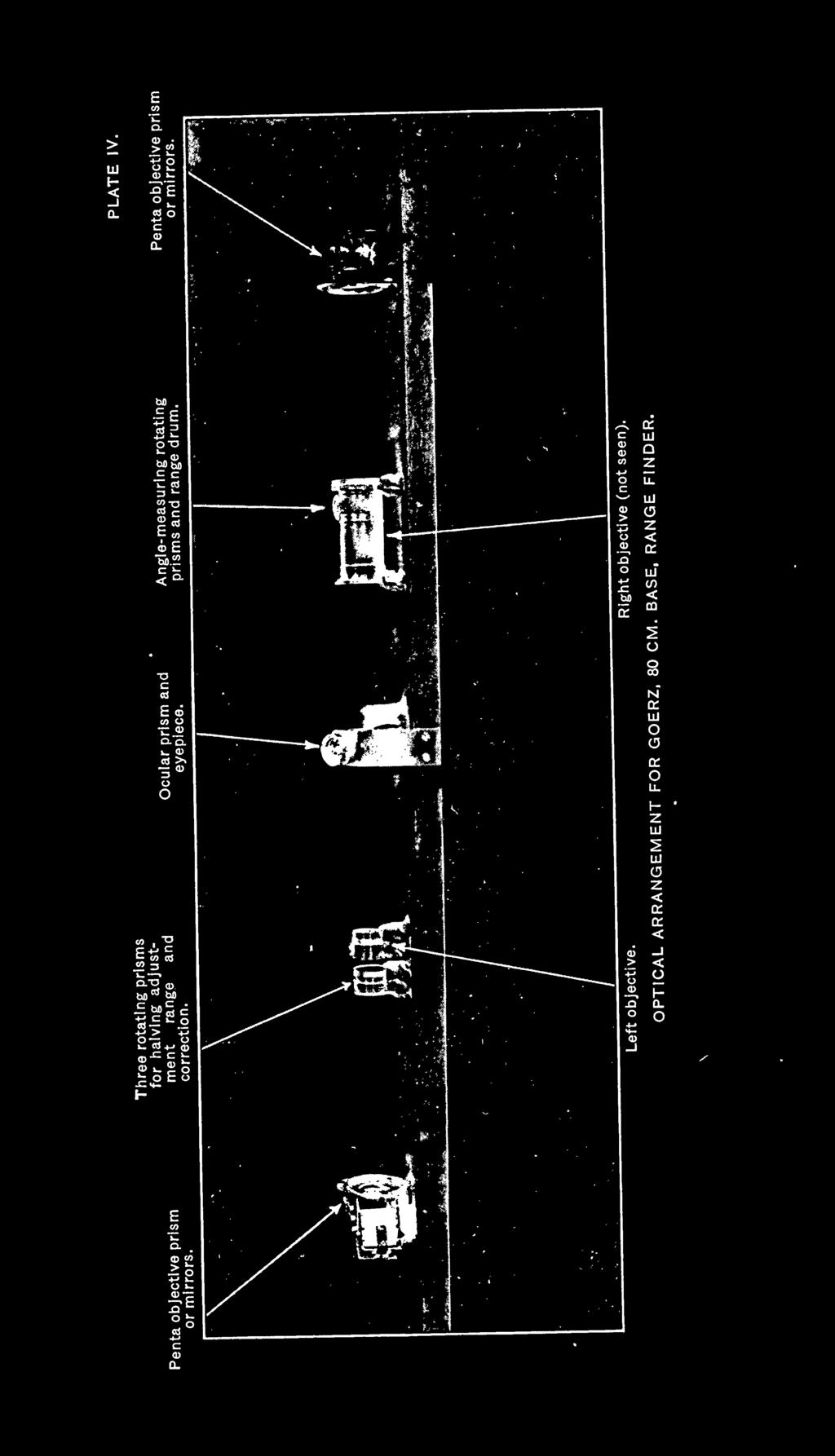
15 through 90 by means of the reflecting prism A. At the right-hand side is the movable telescope corresponding to the telescope at B in figure 2 of our improvised range-finder. In the right-hand telescope the light traverses the objective lens, the angle measuring prism P, the coincident prism D', and the same eyepiece (G and F). As before, the line of sight of the right-hand telescope is turned through^qo by means of the reflecting prism B. Instead of moving the telescope at the right-hand side mechanically, in order to measure the angle DBA (fig. 1), the line of sight of the telescope is moved optically by means of the reflecting prism P. This prism is sometimes called the angle-measuring prism or wedge. The reflecting prism P carries a range scale which is graduated directly in yards of range. Thus, moving the reflecting prism P laterally along AB corresponds to a movement of the line of sight of the right-hand telescope, and the angle which the line of sight of this telescope makes with the line AB (fig. 1) is read in terms of the range AD (fig. 1) on the range drum attached to the reflecting prism. Referring to Plate CA I, if and C'B are parallel rays of light from an object at an infinite distance, they will meet at the center D. If the object is at the finite C and C", then CA will be reflected to D as before, but C"B will be reflected to D'. The angle D'BD is equal to the angle C'BC" and varies with the distance of the observed object. The ray BD' could be made to take the direction of BD by revolving the reflector B, but the amount of this revolution is so small for moderate changes in range and so difficult for accurate measurement that the same result is obtained by the use of the prism P, the reflecting angle of which is very A small. position of the reflecting prism P can be found varying with the distance of the observed object where the reflected ray will pass through the point D, thus meeting the ray CAD. The two coinciding images of the same prisms are so placed at the point D that they reflect the light from both ends of the range-finder into the eyelens F, and the images are actually found at a point in front of the eyelens, the position of the images depending upon the type of the instrument. Since there is a certain position of the prism P which will bring the two halves of the object into coincidence, then a suitably graduated scale attached to the prism and moving with it will record the distance of the object corresponding to the position of the prism. In the actual range-finder various prism and lens combinations are employed in the place of the simple parts shown in Plate I, in Older to obtain the desired erect or invert appearance of the partial images in the field of view (see Plate IV). All the optical elements are inclosed in a tube. As the tube is liable to be distorted as a result


16 10 of the effect of temperature changes, or of handling during the working of the instrument, it is necessary to adopt a type of end reflector that will not alter the direction of the beams of light entering the range-finder even if its position were varied by small amounts. Nearly all, except the earlier range-finders, are made with a prism, known as the pentagonal or Prandl prism, to take the place of the reflectors A,, and B on Plate I. A prism of this type, designed to bend the rays of light through an angle of 90 degrees, consists of a block of glass having two reflecting faces placed at an angle of 45 degrees to one another. It is necessary that these two reflecting faces should be silvered, as the angle of incidence is within the critical angle of glass. Any rotation of such a prism about an axis perpendicular to the column normal plane of the two reflecting surfaces does not affect the direction of the double reflecting beam of light, as the effect of the rotation of one reflecting surface is exactly balanced by the equal rotation of the two reflecting surfaces. Instead of using an angle-measuring prism like P (Plate I) which, slides horizontally along the base of the range-finder, two rotating prisms are often used. These prisms are rotated in opposite directions by gearing connected to the range drum. The actual arrangement of the optical parts used in the Goerz 80 cm. base range-finder are shown on Plate IV. TYPES OF RANGE-FINDERS. There are several different types of self-contained range-finders, three of which are described in this pamphlet, namely, the invert single-coincidence, the invert double-coincidence, and the erect double-coincidence types. All the 80 cm. base Goerz range-finders issued to the service are of the invert single-coincidence type. The Bausch & Lomb instruments, 70 and 80 cm. base are of the invert double-coincidence type except 1 70 cm. base instrument No. 14 which is of the erect doublecoincidence type. In the invert single-coincidence type the entire upper field is inverted but not reversed, right or left, giving the effect as though the lower field was reflected in the sky. In the invert double-coincidence type the narrow strip in the center of the field is inverted, the upper field remaining erect. This type gives a greater effective field for observation and permits coincidence to be made on two edges of the invert field when the target has a vertical straight line, as in a chimney or edge of a building. Its optics, however, are more complex.


17 11 The erect double-coincidence type is similar to the invert doublecoincidence type except that the image in the central narrow strip is erect. GENERAL INSTRUCTIONS. The best denned part of an object should be selected to range on. Coincidence should always be made in the center of the field of view and if possible with the dividing line at right angles to the object observed. Upon the accuracy of the coincidence setting depends the accuracy of the range determination. No difficulty should be experienced on the part of the observer in obtaining good results after a little practice or even at the first attempt, but in range finding as in anything else accuracy increases with practice. It has been found that different observers have what might be called personal errors which diminish as their experience increases. The range observer should therefore be given every opportunity for practice in measuring angles and ranges, and in making the halving adjustments. When both edges of the object are equally well defined the observer should always make his coincidence on the same edge, right or left. Individual observers have obtained better results by so doing than if they used the right edge sometimes and the left edge at other times. It is advisable when time permits to obtain the range by taking the mean of several consecutive readings. With targets moving laterally across the field it is best to adjust the images on the edge from which the targets are moving, and to make the measurements for range while the target field. runs across the Before observing range, the adjustments for height and for distance should be tested, and corrected if necessary. Adjustment for height should always be made before adjustment to correct for errors in distance. See the descriptions of the different range-finders for the methods of making the adjustments for height and distance.

18
 consists of the rangefinder, the tripod, the adjustment bar, the accessories, and the carrying case. The principal parts of the range-finder proper are the A.")
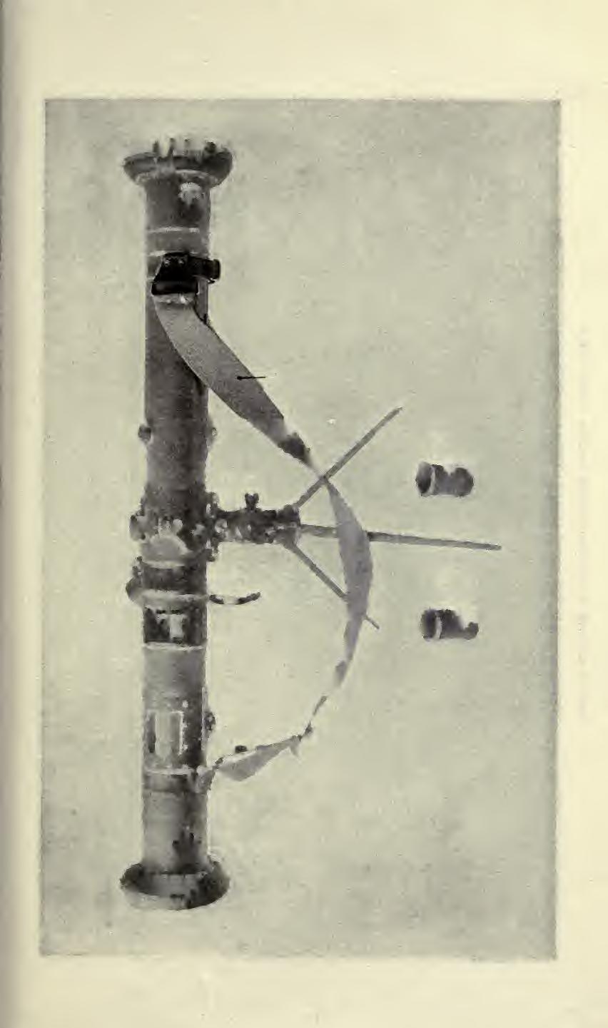
19 GOERZ RANGE-FINDER. (80 CM. BASE.) EQUIPMENT AND GENERAL DESCRIPTION. The instrument (Plates V, VI, and XII) consists of the rangefinder, the tripod, the adjustment bar, the accessories, and the carrying case. The principal parts of the range-finder proper are the A. Eyepiece. B. Finder. C. Measuring screw. D. Range scale. E. Protective cap for height adjustment'screw. F. Protective cap for range adjustment'screw. K. Entrance apertures. K.' L. Locking hook. The tripod consists principally of the M. Hook bolt. N. Legs. O. Metal tubing extension. P. Locking screws for O. Q. Locking lever for N. R. Casing. S. Locking screw for spur. T. Spur. U. Locking screw for pivot. V. Locking screw for tilting joint. W. Elevation screw. The accessories are comprised of X. Adjustment bar. Y. 2 color screens. Z. 2 sun shades. 1 piece shamois skin. 1 brush. Optical data: Invert single-coincidence type. Magnifying power, 10. Actual field of view in degrees, 4. Entrance pupil, 1 inch. Exit pupil, 0.1 inch. Shortest distance measurable, 400 yards. (13)


20 14 Plate IV shows the optical elements mounted in the same relative position as in the instrument. The accuracy of the instruments, even under the most favorable conditions, will be unavoidably influenced by a known error. In the following table the lowest values of these errors are given, but when the air is unsteady or the target is unfavorable, these errors may be increased five times. 400 yards 1 Yards. 500 yards yards yards yards 3. 8 Yards. 900 yards ,000 yards 6 1, 500 yards ,000 yards ,000 yards 54 OPERATION., This type of range-finder may be used in the prone, kneeling, or standing position. The spur (T), Plate VI, is used as a support for the range-finder when in a prone position Where the soil is soft the. spur is pushed as one piece vertically into the ground. For use on hard soil the three parts composing the spur are spread and used as a short tripod. For use with the tripod the spur is folded together, inserted into the casing R of the tripod, and locked securely by locking screw S. The instrument can also be used in the prone and kneeling positions by supporting it with the hands. For use in standing position the tripod legs must first be lengthened by loosening locking screws P and allowing metal tubing extension O to drop out, after which locking screws P are again tightened. If necessary, the spur T can be adjusted in the casing R to suit the height of the observer's eyes. Take the range-finder from the carrying case, with eyepiece turned toward the observer, and seat the instrument firmly on the tripod. Remove the protective hoods from the entrance apertures and put on sun screens Y if necessary, turn range-finder toward the target and fasten locking screw U, release locking screw V, turn rangefinder so that its longitudinal axis is horizontal and relock screw V. Dismounting is accomplished in the reverse order. ADJUSTMENTS. A. ADJUSTMENT FOR HEIGHT. When in sighting at an object the partial images do not touch the dividing line with similar points, so that one image reaches the dividing line before the other (fig. 6, Plate II), the instrument is not in adjustment for height. To correct this error the range-finder must be trained at an object having a sharply defined horizontal line or particularly promi-


21 15 nent point, and the images brought laterally exactly opposite each other by means of the measuring screw. The protective cap E, Plate VI, is then raised and by means of the height-adjustment screw the images of the clearly defined line or prominent point, in both the upper and lower fields, are brought equidistant from the dividing line. Having made this adjustment, test it by turning the touch the dividing line elevating screw W until similar points just (see fig. 5, Plate II). The adjustment made, the protective cap is replaced to guard against unauthorized or accidental shifting. B. ADJUSTMENT FOR DiSTANCE. The adjustment for the correction of errors in distance is made with the adjustment bar, Plates V and VI. This bar is set up not less than 100 yards from the range-finder and directly facing it. The adjustment bar is provided with av finder, by means of which the axis of the bar can be placed at right angles with the line joining the range-finder and the center of the adjustment bar. Both ends of the adjustment bar are marked with a black line. The distance between these lines is the same as that between the centers of the entrance apertures of the range-finder. The targets are made to coincide as shown in figure 9, Plate III, by means of the measuring screw (C) and the reading of the range scale noted. This should be repeated several times to insure accuracy, and if the average reading does not show infinity a readjustment must be made. This adjustment is made by bringing the infinity setting of the range drum opposite the index and making coincidence of the targets by means of the range-adjustment screw (F), Plate VI. To insure accuracy coincidence should be made several times, noting the readings of the scale on the range-adjustment screw. The final adjustment should then be made by setting the range-adjustment screw at its average setting. The protective cap should then be closed and secured to prevent accidental or unauthorized disarrangement. MEASURING RANGES. The eyepiece is provided with an adjustment for individual correction, equipped with a diopter scale. If this correction is not known it should be determined before any attempt is made to measure ranges. The determination of the individual correction is made by turning the eyepiece until the details appear sharply defined in the field of the range-finder. The resulting number on the diopter scale should then be memorized for future use. The color screen is provided to protect the eyes of the observer from a glare of light. The range-finder having been set approximately on the target (if necessary, by means of the open sight), the object is looked for in
, Plate V.")
.")
22 16 the field of view. Movement in azimuth is accomplished by turning the range-finder on the tripod pivot after loosening locking screw (U), (see Plate VI). For use with stationary targets this screw is relocked after the instrument is properly set. The movement in elevation is accomplished by means of the elevation screw (W), Plate V. The field of view of a range-finder of the single coincidence invert type is divided into two parts by a horizontal line. In the lower part the image of the object appears upright, while in the upper part it is inverted (fig. 3, Plate II). By turning the height adjustment screw the images are lined up so that the proper points will touch the dividing line (fig. 4, Plate II). By turning the measuring screw (C), Plate VI, the image is shifted laterally until similar points of the object are exactly above one another (fig. 5, Plate II). The distance is then read on the range scale. With targets which have no prominent vertical lines or points, but show horizontal lines, such as tops of heights, entrenchments, etc., the distance is measured on the horizontal line by setting the instrument vertical (fig. 10, Plate III). For this purpose the locking screw is loosened and the range-finder turned down on the left until vertical. Measurements are taken in the same manner as described above. The image first appears as illustrated in figure 7, Plate II. By turning the measuring screw the partial images are shifted so that the horizontal line is continued exactly on the dividing line (fig. 8, Plate II).
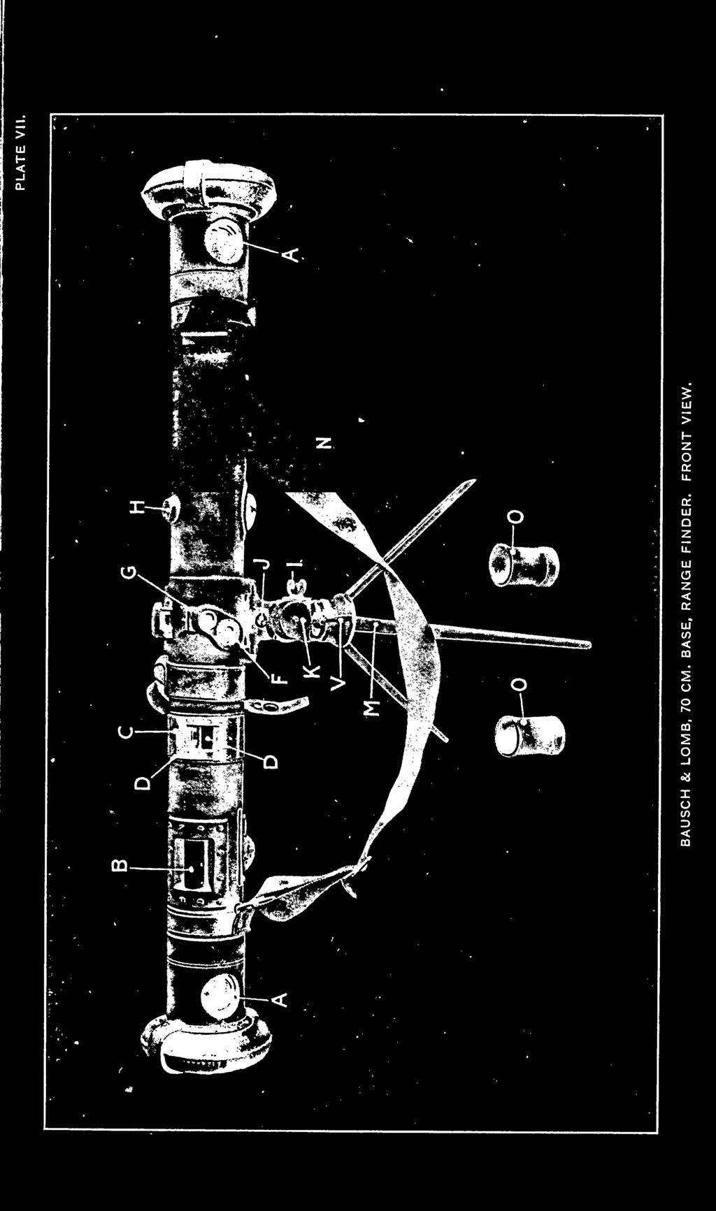
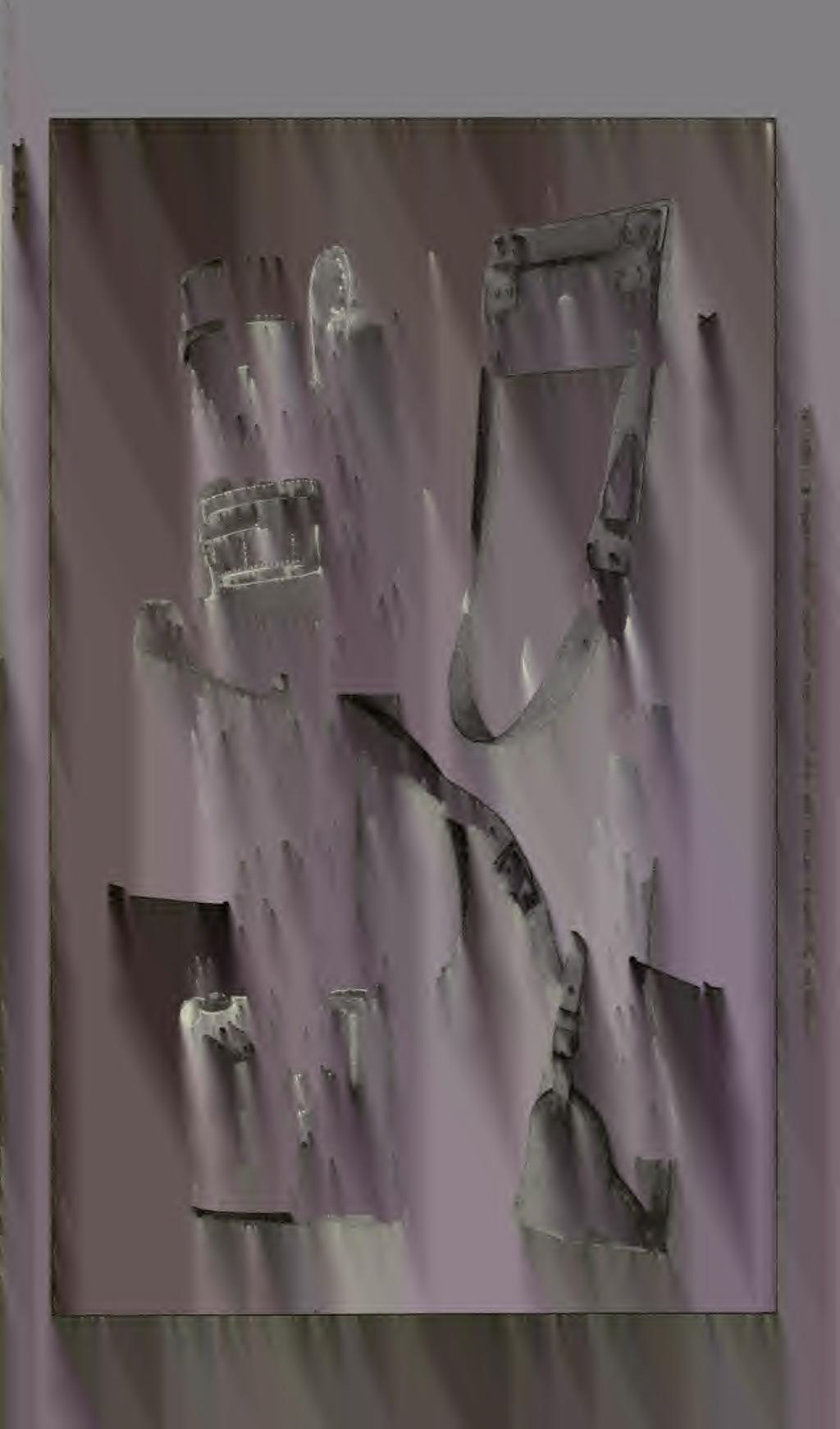
 consists of the range-finder proper, the tripod, the accessories, and the carrying cases (Plate IX).")
. E. Eyepiece. F. Window for illuminating range scale. G. Window for illuminating adjusting marks. H. \"Air\" and \" field \" adjustment. I. Locking screw for pivot. J.")
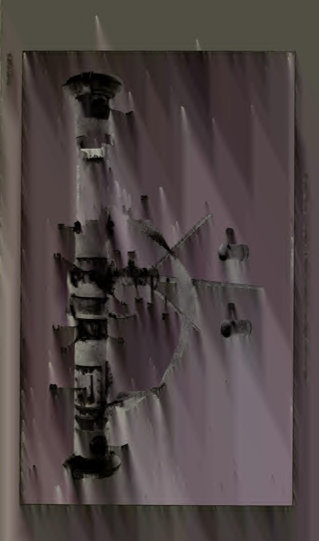
23 BAUSCH & LOME RANGE-FINDER. (70 CM. BASE.) EQUIPMENT AND GENERAL DESCRIPTION. The instrument (Plates VII and VIII) consists of the range-finder proper, the tripod, the accessories, and the carrying cases (Plate IX). The principal parts of the range-finder proper and the tripod mount are the A.- Entrance apertures. B. Range roller. C. Revolving collar (covering rollers). D. Height-adjustment roller. D'. Range-adjustment roller (not seen). E. Eyepiece. F. Window for illuminating range scale. G. Window for illuminating adjusting marks. H. "Air" and " field " adjustment. I. Locking screw for pivot. J. Releasing plunger. K. Elevation screw. L. Casing. M. Spur. N. Shoulder strap. P. Eyepiece cover. R. Range-adjustment levers. S. Reference scale. T. Open sight. V.- Locking lever for leveling device. The accessories are comprised of O. 2 color screens, 1 brush, and 1 piece of chamois. The carrying case equipment (Plate IX) consists of the W. Range-finder, case with tripod. X. Range-finder support. Y. Tripod mount case. Optical data : Invert double-coincidence type. Magnifying power, about eleven times. Actual field of view in degrees, 4. Entrance pupil, 1 inch. Exit pupil, 0.1 inch. Shortest distance measurable, 400 yards. (37)


24 [ j 1, The accuracy of the measurements even under the most favorable conditions will be unavoidably influenced by a known error. In the following table the lowest values of these errors are given, but when the air is unsteady or the target is unfavorable these errors may be increased five times. Yards. 400 yards yards 1:1 I 600 yards yards yards 2. 8 OPERATION. Yards. 900 yards 3. 9 yards ,600 yards 11 2,000 yards 17 3,000 yards 39 The range-finder may be used in the prone, kneeling, or standing position. The spur M is used as a support for the range-finder when in a prone position. Where the soil is soft, the spur is^pushed as one piece vertically into the ground. For use.on hard soil, the three parts composing the spur are spread and used as a short tripod. For use in the standing position without the tripod, a range-finder support is furnished which is hung on the observer's shoulder and holds the instrument to the required height. This instrument can not be adjusted to the vertical position on the tripod. For use with the tripod, the spur is folded together, inserted in the casing L of the tripod, and clamped securely. For use in the standing position, the tripod legs are spread and the spur can be adjusted in the casing to suit the height of the observer's -eyes. ADJUSTMENTS. A. ADJUSTMENT FOR HEIGHT. If, when in sighting at an object, the partial images do not touch with similar points on the line on which coincidence is to be made, the instrument is out of adjustment for height. To correct for this error, the range-finder must be trained on some object having sharply defined details and the images brought exactly opposite each other by means of the range roller (B), Plate VII. The revolving cover (C) is moved back to uncover the height adjustment roller (D') and the images of similar points of the object brought equidistant from the dividing line upon which coincidence is to be made by turning the roller (D'). Both images may then be made to touch the dividing line simultaneously by turning the elevation screw (K). The heightadjustment roller should always be covered when not in use. B. ADJUSTMENT FOR DISTANCE. These Bausch & Lomb range-finders have no adjustment bar, but are provided with an internal adjusting device. The adjustment for correction of errors in distance is made as follows: Turn down both
, Plate VII, marked \" Stadia adjustment\" is then released and the collar turned until the mark \" Stadia adjustment\" is opposite the arrow on the")
 (see")
25 19 range-adjustment levers (R), Plate VIII, until vertical; this throws the adjustment marks into the field of view. The locking screw on the revolving collar (C), Plate VII, marked " Stadia adjustment" is then released and the collar turned until the mark " Stadia adjustment" is opposite the arrow on the instrument. The range-adjustment roller (D') is now exposed. The range scale having been previously set to read infinity the single adjusting mark is brought exactly in the middle of the double adjusting marks by turning the range adjustment roller (D') (see fig. 11, Plate III). The position is then read on the scale (S), Plate VIII. Should there be any variation in the reading of the scale (S) in the several trials the final adjustment should be made by setting the scale at the average setting. The revolving cover should then be replaced and the range adjustment levers turned to a horizontal position. MEASURING RANGES. The eyepiece is provided with an adjustment for individual correction, equipped with a diopter scale. If this correction is not known it should be determined before any attempt is made to measure ranges. The determination of the individual correction is made by turning the eyepiece until the details of distant objects appear sharply defined. The resulting number on the diopter scale should then be memorized for future use. The range-finder having been set approximately on the target, the instrument is leveled by loosening the locking lever (V). Movement in azimuth is accomplished by loosening the locking screw (I). Movement in elevation is accomplished by the elevating screw (K), by means of which the points to be ranged on are brought to the coincidence line. These range-finders being of the double-coincidence type have a field divided into three parts. The lower field is erect, the narrow band in the center is inverted and the upper field is erect. Coincidence therefore may be made on either dividing line. These instruments are provided with an "air" and " field'' adjustment by which the position of the inverted image may be shifted to make coincidence on either line of separation. When the knob (H) is turned ' in the direction of the arrow marked "field," coincidence is had on the lower line of 7 separation; when turned to the arrow marked "air/ coincidence is had on the upper line. By turning the range-roller (B) the image is shifted laterally until the vertical edge or points range on arc exactly above one another; the range is then made on the scale. No provision has been made in these mounts for rotating the rangefinder in a vertical position.


26
 consists of the rangefinder proper, the tripods the accessories, and the carrying cases.")
. Range-correction reference index. Cover for ginible joint screw. Internal adjusting levers. Amber and smoked glass lever.")

27 BAUSCH & LOME RANGE-FINDER. (80 CM. BASE.) EQUIPMENT AND GENERAL DESCRIPTION. The instrument (Plates X, XI, and XII) consists of the rangefinder proper, the tripods the accessories, and the carrying cases. The principal parts of the range-finder proper and of the tripods and mount are: A B C D F G H I J M O P E Entrance apertures. Range roller. Height-adjusting roller (under slide). Range-correction knob. Eyepiece. Range scale (under slide). Range-correction reference index. Cover for ginible joint screw. Internal adjusting levers. Amber and smoked glass lever. Eyepiece cover. Open sight. Instrument-carrying strap. Short tripod and mount: Q R S T N Releasing plunger. Tilting knob. Elevation knob. Azimuth clamp knob. Spur. Long tripod: W Tripod legs. -Tripod clamp knob. U - V -Tripod casing and head. The accessories are comprised K of Range correction key. 1 brush and 1 piece of chamois. The carrying case equipment consists of (a) A large case, with straps, for range-finder proper and long tripod. A container is provided in the end of this case for the accessories. (&) A small carrying case (L) for tripod mount and short tripod. (21)


28 22 Optical data: Invert double-coincidence type. Actual field of view in degrees, 4. Power, Entrance pupil, 0.99 inch. Exit pupil, 0.09 inch. Shortest distance measurable 400 yards. The accuracy of the measurements even under the most favorable conditions will be unavoidably influenced by a known error. In the following table the lowest values of these errors are given, but when the air is unsteady or the target is unfavorable, these errors may be increased five times. 400 yards 1 Yards. 500 yards yards yards yards : 3. 8 OPERATION. Yards. 900 yards 4.9 1,000 yards 6 1,500 yards ,000 yards ,000 yards 54 This type of range-finder can be used in the prone, kneeling, standing position. The spur is used as a support for the rangefinder when in the prone position. Where the soil is soft, the spur is pushed as one piece vertically into the ground. For use on hard soil, the three parts composing the spur are spread and used as a short tripod. For use with the long tripod, the spur is folded together and inserted into casing (V), Plate X, of.the tripod, and locked securely by means of the tripod clamp knob (U). The spur should be adjusted in the tripod casing to suit the height of the observer's eye. The instrument can also be used in the prone or kneeling position by supporting it with the hands. If, ADJUSTMENTS. A. ADJUSTMENT FOR HEIGHT. when in sighting at an object, the partial images do not touch the dividing line with similar points, so that one image reaches the dividing line before the other (fig. 6, Plate II), the instrument is not in adjustment for height. To correct this error, the rangefinder must be trained at an object having a sharply defined horizontal line or particularly prominent point and the images brought laterally exactly opposite each other by means of the measuring screw. The height-adjusting roller (c) Plate X is then exposed by moving the slide marked "halving adjuster" to one side and the adjustment made by turning the roller until the images of a clearly defined line or prominent point are brought equidistant from the dividing line in each field (see fig. 4, Plate II). The height of the or


29 23 images in both fields is controlled by means of the elevation knob (S), Plate X. The adjustment made, the protective slide is replaced to guard against unauthorized or accidental shifting. B. ADJUSTMENT FOR DISTANCE. See the description of the method of making this adjustment for the 70-cm. Bausch & Lomb range-finder, page 18. The range scale should be set to read infinity before making this adjustment. Bring the two triple mirror prisms in use by pushing the actuating levers (J), Plate XI, downward. The illuminator for the adjusting mark is opposite the eyepiece. This illuminates the adjusting mark on the outward prism and reflects it back through the ocular prism, right telescope, right triple-mirror prism, left triple-mirror prism, left telescope, and to the ocular prism again, where this reflected mark will appear -n the same horizontal plane as the index slot, and, if the instrument is not in adjustment, will not be equidistant from the sides of the slot. Place key on range correction knob (D), Plate X, and turn until the reflected mark is equidistant from the sides of the index slot. (See fig. 12, Plate III.) Observe the reading on the range correction reference index (H), Plate XI. Repeat this operation at least three times and then set index (H) at the mean of the three readings. Throw the triplemirror prisms out of the field by means of the actuating levers (J) and remove the Adjustment key. The instrument should now be in adjustment for reading correct ranges. MEASURING RANGES. The eyepiece is provided with an adjustment for individual correction, equipped with diopter scale and index. If this correction is not known, it should be determined before any attempt is made to measure ranges. The determination of the individual correction is made by turning the eyepiece until the details of distant objects appear sharply defined. The resulting number on the diopter scale should then be ^memorized for future use. Having the instrument mounted upon either tripod, rotate the protective bands so as to expose the entrance apertures (A), release azimuth clamp (T), and turn the range-finder toward the target. Tilt the range-finder until approximately horizontal by means of the tilting knob (R), and look for the target in either open sight (P), using the elevation knob (S) to elevate or depress the line of sight as necessary. These range-finders being of the double-coincidence type have the field divided into three parts. The lower field is erect, the narrow band in the center is inverted, and the upper field is erect. Coincidence, therefore, must always be made on the lower dividing line.
 until similar points of the target?")
, Plate X, until similar points of the image in the central field are exactly above the same points in")

30 24 Having placed the image of the target in the center of the field of view, elevate or depress the line of sight by/tneans of the elevation knob (S) until similar points of the target?, in the upper and lower fields, are equidistant from the lower dividing line. Turn the range roller (B), Plate X, until similar points of the image in the central field are exactly above the same points in the lower field. (See fig. 5, PL II.) The range is then read on the range scale. With targets which have no vertical points or lines but show horizontal lines, such as tops of heights, intrenchments, etc., the ranges are measured on the horizontal line by holding the instrument vertical. In this connection see also paragaph " 7 General instructions/ 11 of this pamphlet. >


31 CARE AND PRESERVATION. Under no circumstances shall any range-finder be disassembled or adjusted except by a skilled mechanic upon order by an Ordnance Officer or by an arsenal especially equipped for instrument work. The interior is sealed against dust and moisture and any disassembling will unseal the internal parts and may cause serious damage to the instrument. Every precaution should be taken to preserve the rangefinder from unnecessary - injury. It should not be thrown on the ground or subjected to any avoidable shocks, strains, neglect, or other ill usage. To care for the instrument properly those responsible for it should familiarize themselves with the functions of its various parts, the methods of adjusting, and the proper method of caring for the mechanical and optical parts. The instrument should be kept in a dry place. The working parts should be oiled regularly though, sparingly with oil issued by the Ordnance Department. Proper care should be taken that no oil drops upon or reaches the optical surfaces or other parts which do not require oiling. The range-finder should be protected as much as possible in wet When rain ceases or operations are over the outside of the weather. range-finder should be wiped off with a cloth. The end windows, the scale window, and the eyepiece should be wiped with a piece of clean chamois skin especially kept for the purpose. Dry dust is removed with the brush. The metal work should be rubbed down with a dry cloth; cleaning paste must not be used on any part of the instrument. The greatest care should be taken not to allow any oil or grease to get on any of the windows, lenses, or prisms, nor should they be touched with the fingers. If in any case moisture is found collected on the inner surface of the windows or the internal optical parts the end plates to which the padded buffers are attached should be removed for a short time to allow a current of air to pass through the tube, but this should only be done in dry weather, never in rain or fog, or if smoke or dust is about the range-finder. All work on the range-finder, such as unnecessary turning of screws, etc., not incident to its use or cleaning, is strictly forbidden. WAR DEPARTMENT, OFFICE OF THE CHIEF OF ORDNANCE, Washington, December 9, Form No Ed. June ,000. (25)

32

33


34

35 DIAGRAM TO ILLUST&rTC THE PRINCIPLE: or RANGE ~FINDEKS,

36


37 PLATE II. FIG. 3. FIG. 4. FIG. 5. FIG. 6. FIG. 7. FIG. 8.
38


39 PLATE III. FIG. 9. FKS.II. FIG. 10

40

41

42


43 PLATE V. It.. GOERZ, 80 CM. BASE, RANGE FINDER. FRONT VIEW.


44


45 PLATE VI. GOERZ, 80 CM. BASE, RANGE FINDER. REAR VIEW.

46
47

48


49 BAUSCH & LOMB, 70 CM. BASE, RANGE FINDER. REAR VIEW. fc PLATE VIM.


50

51
52


53 PLATE X. 6 BAUSCH & LOMB, 80 CM. BASE, RANGE FINDER. FRONT VIEW.

54


55 PLATE XI, BAUSCH & LOME, 80 CM. BASE, RANGE FINDER. REAR VIEW.
56


57 PLATE XII, GOERZ, 80 CM. BASE, RANGE-FINDER CARRYING CASE. BAUSCH & LOMB, 80 CM. BASE, RANGE FINDER, WITH SHORT TRIPOD.

58


59


60


61


62

63


64
Owner's Manual NSL100B BUILDERS LEVEL NSL500B TRANSIT LEVEL
 Owner's Manual NSL100B BUILDERS LEVEL NSL500B TRANSIT LEVEL 1 1. CONTENTS 2. Nomenclature page 3 3. Care and Maintenance page 4 4. Using your Instrument 4.1 Setting up your Instrument page 5 4.2 Stadia
22X Builder s Transit Level Model No Instruction Manual
 2595H 7/29/09 10:15 AM Page 1 22X Builder s Transit Level Model No. 40-6910 Instruction Manual Congratulations on your choice of this 22X Builder s Transit Level. We suggest you read this instruction manual
Owner's Manual. for AUTOMATIC LEVEL. NBL Series. FOR CUSTOMER SERVICE, PARTS & REPAIR, CALL Toll Free:
 Owner's Manual for AUTOMATIC LEVEL NBL Series FOR CUSTOMER SERVICE, PARTS & REPAIR, CALL Toll Free: 1-888-247-1960 1 1. CONTENTS 2. Nomenclature page 3 3. Care and Maintenance page 4 4. Using your Instrument
Directions for use
 Directions for use 40070 40080 60050 70060 70076 80060 90060 900114 Fig. 1 Fig. 1A Fig. 2 Fig. 3 Fig. 4 Fig. 5 Fig. 6 Fig. 7 english ENGLISH DIRECTIONS FOR USE 1 Tripod Leg 2 Tripod Leg Adjusting Screw
NEW STANDARD SEXTANT OF THE U. S. NAVY
 NEW STANDARD SEXTANT OF THE U. S. NAVY Director of the United States of America Hydrographic Office has sent to the International Hydrographic Bureau the following data relating to the new Standard Sextant
22X Builder s Level Model No Instruction Manual
 2594H 7/29/09 10:12 AM Page 1 22X Builder s Level Model No. 40-6900 Instruction Manual Congratulations on your choice of this 22X Builder s Level. We suggest you read this instruction manual thoroughly
Kalinka Optics Warehouse User Manual Kobra AK Side Mount Red Dot Sight Manual
 Kalinka Optics Warehouse User Manual www.kalinkaoptics.com Kobra AK Side Mount Red Dot Sight Manual CONTENTS 1. Introduction... 4 2. Purpose... 4 3. Specifications... 4 4. Components and Equipment Provided...
C A S S I N I TRACKER
 C A S S I N I TRACKER ASTRONOMICAL REFLECTOR T ELESCOPE SERIES #C-80080TR #C-1100102TR #C-1000120TR #C-1000120TREF #C-900135TR COSMO BRANDS INC. WWW.COSMOSOPTICS.COM 2 CASSINI REFLECTING TELESCOPE OPERATING
ZFK 4 X 25. Description and Utilization Instructions
 1. Clarification of Concept The ZFK 4 x 5 is a telescopic sight with fixed magnification with dual cross hair adjustments, central viewing, and attached mount. ZFK 4 X 5 Description and Utilization Instructions.
BINOCULAR STEREOSCOPIC MICROSCOPE MBS-10. User Manual
 BINOCULAR STEREOSCOPIC MICROSCOPE MBS-10 User Manual ATTENTION! Мicroscope design may differ somewhat from description in this manual. 2 1 - PURPOSE The MBS-10 microscope is intended for observing both
Telescope. 1. Read these instructions carefully and familiarise yourself with the procedure before assembling the unit.
 Telescope a Simple assembly instructions- Please keep for future reference IMPORTANT 1. Read these instructions carefully and familiarise yourself with the procedure before assembling the unit. 2. Check
saxon Instruction Manual saxon Grandeur Brass Telescope High quality optics
 saxon High quality optics Instruction Manual saxon Grandeur Brass Telescope WARNING! Do not use the telescope to look at the sun without an appropriate solar filter. Looking at or near the sun can result
SCHIEBER TELESCOPES. Unique, High-Quality Telescopes
 SCHIEBER TELESCOPES Unique, High-Quality Telescopes 3.5 Refractor Astrophotography Bundle - Strike 90 PLUS Telescope Assembly Instructions and Digital Eyepiece Camera Instructions. (1) telescope assembly
WATTS MICROPTIC ALIDADE OPERATING INSTRUCTIONS 20-7
 WATTS MICROPTIC ALIDADE 20-7 OPERATING INSTRUCTIONS WATTS Operating Instructions for the WATTS MICROPTIC ALIDADE SA100 SA101 RANK PRECISION INDUSTRIES METROLOGY DIVISION Survey Equipment Sales Langston
Operating Instructions Spectro-Goniometer Student. 1 Functional Elements. 2 Safety Precautions. Figure 1: Spectro-Goniometer Student
 Operating Instructions Spectro-Goniometer Student 1 Functional Elements Figure 1: Spectro-Goniometer Student 1. Adjustable entrance slit, holding screw for slit cover 2. Lock ring fixing entrance slit
取扱説明書 /INSTRUCTION MANUAL 自動レベル /AUTOMATIC LEVEL AT-B2/B3/B4 FC10386-A012-02
 取扱説明書 /INSTRUCTION MANUAL 自動レベル /AUTOMATIC LEVEL AT-B2/B3/B4 FC10386-A012-02 SURVEYING INSTRUMENTS INSTRUCTION MANUAL AUTOMATIC LEVEL AT-B2/B3/B4 Thank you for selecting the AT-B2/B3/B4. Please read this
ASTRO-PHYSICS, INC. POLAR ALIGNMENT TELESCOPE
 Polar Alignment Telescope ASTRO-PHYSICS, INC. POLAR ALIGNMENT TELESCOPE This polar axis telescope will help you align your mount with the Celestial Poles. When your mount is properly aligned, your telescope's
1 YEAR LIMITED WARRANTY TELESCOPES
 1 YEAR LIMITED WARRANTY TELESCOPES BARSKA Optics, as manufacturer, warrants this new precision optical product to be free of original defects in materials and/or workmanship for the length of time specified
CIV : THEODOLITE ADJUSTMENT
 Unit CIV2202: Surveying 10.1 CIV2202.10: THEODOLITE ADJUSTMENT Table of Contents PREVIEW...2 Introduction...2 Objectives...2 Readings...2 REGULAR CHECKS...2 Tripod...2 Footscrews...2 Tribrach head...3
NcSTAR SHOOTER II SERIES SCOPE
 NcSTAR SHOOTER II SERIES SCOPE Congratulations on the purchase of your New NcSTAR Shooter II Series Scope! The Shooter II Series of scopes gives you many great options, so you can choose the scope that
INTRODUCTION TO ENGINEERING SURVEYING (CE 1305)
") INTRODUCTION TO ENGINEERING SURVEYING (CE 1305) Linear Measurements Sr Dr. Tan Liat Choon Email: tanliatchoon@gmail.com Mobile: 016-4975551 1 EDM, TOTAL STATION, PRISM AND POLE 2 ELECTROMAGNETIC DISTANCE
INTRODUCTION TO ENGINEERING SURVEYING (CE 1305) Linear Measurements Sr Dr. Tan Liat Choon Email: tanliatchoon@gmail.com Mobile: 016-4975551 1 EDM, TOTAL STATION, PRISM AND POLE 2 ELECTROMAGNETIC DISTANCE
C A S S I N I. MODEL : C EQ3 900mm X 135mm COSMO BRANDS INC.
 C A S S I N I MODEL : C-900135EQ3 900mm X 135mm COSMO BRANDS INC. WWW.COSMOSOPTICS.COM 2 C A S S I N I C-900135EQ3 TELESCOPE OPERATING INSTRUCTIONS INTRODUCTION CONGRATULATIONS ON YOUR PURCHASE OF THE
5-25x56 PMII PSR With Double Turn
 Page 1 of 20 5-25x56 PMII PSR 5-25x56 PMII PSR With Double Turn Page 3 of 20 1. Scope description... 5 1.1 Introduction... 5 1.2 Safety instructions... 5 2. Technical data... 6 2.1 General data... 6 2.2
Electron Microscopy Sciences INSTRUCTION MANUAL. Stereo Microscopes Non-illuminated Stands
 Electron Microscopy Sciences 1 INSTRUCTION MANUAL Stereo Microscopes Non-illuminated Stands Model GL7-207: Binocular, 6.5:1 Zoom Ratio 10X to 65X, smooth ball bearing construction and Model GL7-307: Trinocular,
CASSINI CQR-800 OPERATING INSTRUCTIONS INTRODUCTION
 HQR-800 CASSINI CQR-800 OPERATING INSTRUCTIONS INTRODUCTION CONGRATULATIONS ON YOUR PURCHASE OF THE CASSINI CQR-800 TELESCOPE. THIS TELESCOPE HAS BEEN PRODUCED TO PRECISE SPECIFICATIONS. PRIOR TO USING
ASTRO-PHYSICS, INC. POLAR ALIGNMENT TELESCOPE (PASILL2)
") OBJECTIVE LENS ASTRO-PHYSICS, INC. POLAR ALIGNMENT TELESCOPE (PASILL2) This model shipped from January 2001 through July 2002. It fits all 400, 600, 600E, 800, 900 and 1200 models (except the original
OBJECTIVE LENS ASTRO-PHYSICS, INC. POLAR ALIGNMENT TELESCOPE (PASILL2) This model shipped from January 2001 through July 2002. It fits all 400, 600, 600E, 800, 900 and 1200 models (except the original
BINOCULAR. 50 mm Tactical Binocular Manual HD R/T
 50 mm Tactical Binocular Manual HD R/T The Viper Tactical Binocular Built on a tough, durable roof prism design, the 50 mm Viper HD R/T binocular has brilliant optics that can be relied upon in demanding
Instruction Manual. Model #: (Reflector) Lit #: / 06-07
 Lit #: / 06-07") Instruction Manual Model #: 49114500 (Reflector) Model #: 49060700 () Model #: 49070800 () Lit #: 93-0468 / 06-07 PARTS DIAGRAM C E D B A F G H I J NOTE: Actual product may have improvements that are not
Instruction Manual Model #: 49114500 (Reflector) Model #: 49060700 () Model #: 49070800 () Lit #: 93-0468 / 06-07 PARTS DIAGRAM C E D B A F G H I J NOTE: Actual product may have improvements that are not
Assembly Manual for the Brevard Astronomical Society 16 inch F4.5 Dobsonian Telescope Brevard Astronomical Society P.O. Box 1084 Cocoa, FL 32922
 BAS 16 Telescope Manual Rev 1 Assembly Manual for the Brevard Astronomical Society 16 inch F4.5 Dobsonian Telescope Brevard Astronomical Society P.O. Box 1084 Cocoa, FL 32922 TABLE OF CONTENTS SECTION
Ph 3455/MSE 3255 Experiment 2: Atomic Spectra
 Ph 3455/MSE 3255 Experiment 2: Atomic Spectra Background Reading: Tipler, Llewellyn pp. 163-165 Apparatus: Spectrometer, sodium lamp, hydrogen lamp, mercury lamp, diffraction grating, watchmaker eyeglass,
SKELESCOPE REFLECTOR TELESCOPE WITH TABLE TOP TRIPOD SK-100 INSTRUCTION MANUAL
 TM SKELESCOPE REFLECTOR TELESCOPE WITH TABLE TOP TRIPOD SK-100 INSTRUCTION MANUAL TABLE OF CONTENTS Introduction Box Contents / Visual Key Diagram Telescope Assembly Setting up Your Telescope Attaching
Any first year text, sections on atomic structure, spectral lines and spectrometers
 Physics 33 Experiment 5 Atomic Spectra References Any first year text, sections on atomic structure, spectral lines and spectrometers Any modern physics text, eg F.K. Richtmeyer, E.H. Kennard and J.N.
THE DIFFRACTION GRATING SPECTROMETER
 Purpose Theory THE DIFFRACTION GRATING SPECTROMETER a. To study diffraction of light using a diffraction grating spectrometer b. To measure the wavelengths of certain lines in the spectrum of the mercury
LEAPERS, INC. RED/GREEN DOTS
 LEAPERS, INC. 1 RED/GREEN DOTS range estimating scopes UTG reticle intensified scopes TOTAL SOLUTION TO YOUR NEEDS -COMMITMENT TO BEST QUALITY, BEST VALUE AND BEST SERVICEwww.LEAPERS.com 32700 Capitol
Instruction Manual. Made in Japan
 Instruction Manual www.ultimax6.eu Made in Japan Congratulation on the purchase of your new UltimaX scope! Introduction These instructions are provided to guide you in the correct use of the riflescope.
Automatic Level NP-732
 INSTRUCTIONS FOR USE Automatic Level NP-732 Contents Before use 2 1.Nomenclature. 3 2.Operation....4 2-1 Preparing before surveying...4 2-2 Surveying method..........5 2-2-1 Measuring altitude difference...5
RP-200 TELESCOPE Instruction Manual
 2070 5th Avenue Ronkonkoma, NY 11779 Phone: 631-963-5000 Fax: 631-427-6749 For information, call toll-free: 1-800-967-8427 info@carson.com / sales@carson.com / www.carson.com RP-200 TELESCOPE Instruction
COMMODORE BRASS TELESCOPE ZHUMELL COMMODORE BRASS TELESCOPE
 3 0 15 15 E OWNER S MANUAL COMMODORE BRASS TELESCOPE ZHUMELL COMMODORE BRASS TELESCOPE 5 W 60 W 30 W 45 W Zhumell customers know that there are plenty of ways to experience the world. They also understand
EE 1/3.5х14 U EE 1/3.5х14 U
 EE 1/3.5х14 U EE 1/3.5х14 U EE 1/3.5х14 U Table of contents 14 Item No. 1. 2. 3. 4. 5. 6. 7. 8. 9. Section Description of sight Purpose Specification Complete set Design and Principle of Operation Rules
Telescope Sight 4 X 24 for G3 Rifle
 Telescope Sight 4 x 24 For G3 Rifle Telescope Sight 4 X 24 for G3 Rifle Instruction Manual HECKLER & KOCH, INC. 2148 Pacific Boulevard Sterling, Virginia 20166-8903 U.S.A. TEL. (703) 450-1900 TELEFAX (703)
RECON. How to Setup the Telescope to Observe. This guide will show you how to setup your telescope for observing. Written By: Brittany McCrigler
 RECON How to Setup the Telescope to Observe This guide will show you how to setup your telescope for observing. Written By: Brittany McCrigler 2017 recon.dozuki.com Page 1 of 30 INTRODUCTION This guide
USER MANUAL REFLEX SIGHT. Ultra Shot Z Series. English / Francais / Español / Deutsch
 USER MANUAL REFLEX SIGHT Ultra Shot Z Series English / Francais / Español / Deutsch ABOUT SIGHTMARK Sightmark offers a wide range of products that include red dot scopes, reflex sights, rangefinders, riflescopes,
DISPERSION OF A GLASS PRISM
 PH2 page 1 DISPERSION OF A GLASS PRISM OBJECTIVE The objective of this experiment is to analyze the emission spectrum of helium and to analyze the dispersion of a glass prism by measuring the index of
The 50mm Viper R/T binocular is equipped with the Vortex R/T Ranging reticle, designed to assist the user in calculating distances.
 With a tough and durable roof prism design and brilliant optics, the Viper R/T can be relied on in the worst conditions thanks to Vortex s premium XD glass and XR lens coatings. The 50mm Viper R/T binocular
Orion StarBlast 4.5" Telescope
 Orion StarBlast 4.5" Telescope INSTRUCTION MANUAL 507-328-2309 www.rochesterskies.org WARNING: Never look directly at the Sun through any telescope or its finder scope even for an instant as permanent
5-25x56 PMII PSR Illuminated with Double Turn
 Page 1 of 20 5-25x56 PMII PSR Illuminated with Double Turn Page 3 of 20 1. Scope description... 5 1.1 Introduction... 5 1.2 Safety instructions... 5 2. Technical data... 6 2.1 General data... 6 2.2 Dimensions...
Automatic Level Maintenance Manual SAL-XX W/ AIR DAMPENED COMPENSATOR
 Automatic Level Maintenance Manual SAL-XX W/ AIR DAMPENED COMPENSATOR CST/Berger 2001 SAL 20/24/28/32 PAGE 1 REV. C 071803 Automatic Level Maintenance Manual User Calibration and Testing... 3 Circular
SpecterOS4x Optical Sight Operation Manual
 SpecterOS4x Optical Sight Operation Manual ARMAMENT TECHNOLOGY INCORPORATED 3045 ROBIE STREET, SUITE 113 HALIFAX NS B3K 4P6 CANADA sales@armament.com www.armament.com TABLE OF CONTENTS CHAPTER 1 DESCRIPTION,
CASSINI CQR-120 OPERATING INSTRUCTIONS
 CASSINI CQR-120 OPERATING INSTRUCTIONS INTRODUCTION CONGRATULATIONS ON YOUR PURCHASE OF THE CASSINI CQR-120 TELESCOPE. THIS TELESCOPE HAS BEEN PRODUCED TO PRECISE SPECIFICATIONS. PRIOR TO USING YOUR NEW
2-7x32. Instruction manual
 In the event that you should require service for your Nikon RIFLESCOPE, please send it directly to: Nikon Scope Service 841 Apollo Street, Suite 100 El Segundo, CA. 90245-4721 1-800-Nikon SV. 2-7x32 Manufacturer:
Galileoscope Assembly Instructions
 Galileoscope Assembly Instructions To begin, open the exterior box flaps to reveal the interior box. Under one flap, but not the other, you ll find two holes, as shown at right. Place a finger and thumb
Platinum Series. 6-30x56 Front Focal Plane Scope. with Patent Pending DEKA MIL Reticle. DEKA MIL reticle for unsurpassed accuracy at long range
 6-30x56 Front Focal Plane Scope with Patent Pending DEKA MIL Reticle DEKA MIL reticle for unsurpassed accuracy at long range PA6-30X56FFP-DEKA-AMS Platinum Series 1. Turn the Power Ring to a high setting,
RP-100 TELESCOPE Instruction Manual
 2070 5th Avenue Ronkonkoma, NY 11779 Phone: 631-963-5000 Fax: 631-427-6749 For information, call toll-free: 1-800-967-8427 info@carson.com / sales@carson.com / www.carson.com RP-100 TELESCOPE Instruction
DWT-10 Instruction Manual
 DWT-10 Instruction Manual For Customer Service Call (781) 848-7702 or Fax (781) 848-8022 Congratulations on your choice of this David White Electronic Digital Transit. We suggest that you read this instruction
SpecterOS3.0 Optical Sight Operation Manual
 SpecterOS3.0 Optical Sight Operation Manual ARMAMENT TECHNOLOGY INCORPORATED 3045 ROBIE STREET, SUITE 113 HALIFAX NS B3K 4P6 CANADA sales@armament.com www.armament.com Table of Contents 1. Introduction..
AGES CF600PM. 50 mm Telescope w/ AZ Pan Tilt Mount Instruction Manual. WARNING! SUN HAZARD: Never look directly at the sun with this device.
 AGES CF600PM 50 mm Telescope w/ AZ Pan Tilt Mount Instruction Manual WARNING! SUN HAZARD: Never look directly at the sun with this device. 1 WARNING: Never attempt to observe the sun with this telescope.
LT8-300LTU Owner s Guide
 LT8-300LTU Owner s Guide LT8-300LTU LT8-300LTULP FOR CUSTOMER SERVICE, PARTS AND REPAIR CALL (765) 581-4097 www.davidwhite.us.com IMPORTANT: IMPORTANT : IMPORTANTE: Read Before Using Lire avant usage Leer
Appendix 2: Disassembling and Assembling the Telescopes and the Celestron Equatorial Mounts
 Appendix 2: Disassembling and Assembling the Telescopes and the Celestron Equatorial Mounts Disassembling (classroom) 1. The mount must be locked with the telescope situated horizontally. Note the telescope
Premier Heritage 3-15X50 User Manual
 Premier Heritage 3-15X50 User Manual 175 Commonwealth Ct. Winchester, VA 22602 USA Phone: 540-868-2044 Email: info@premierreticles.com Website: www.premierreticles.com Warning: Failure to follow the instructions
Optics. Measuring the line spectra of inert gases and metal vapors using a prism spectrometer. LD Physics Leaflets P
 Optics Spectrometer Prism spectrometer LD Physics Leaflets P5.7.1.1 Measuring the line spectra of inert gases and metal vapors using a prism spectrometer Objects of the experiment Adjusting the prism spectrometer.
Tutorials. 1. Autocollimator. Angle Dekkor. General
 Tutorials 1. Autocollimator General An autocollimator is a Precise Optical Instrument for measurement of small angle deviations with very high sensitivity. Autocollimator is essentially an infinity telescope
E. K. A. ADVANCED PHYSICS LABORATORY PHYSICS 3081, 4051 FRAUNHOFER DIFFRACTION
 E. K. A. ADVANCED PHYSICS LABORATORY PHYSICS 3081, 4051 FRAUNHOFER DIFFRACTION References for Fraunhofer Diffraction 1. Jenkins and White Fundamentals of Optics. Chapters on Fraunhofer diffraction and
Altazimuth Mount. Altazimuth Mount
 instruction Manual Orion VersaGo II HD Altazimuth Mount #10104 Orion VersaGo II Altazimuth Mount #10105 #10104 #10105 Providing Exceptional Consumer Optical Products Since 1975 OrionTelescopes.com Customer
THE LOSMANDY G-11 MOUNT
 Checking the parts THE LOSMANDY G-11 MOUNT Depending on which accessories you ordered, your G-11 mount was shipped in four or more boxes. The contents of each box are as follows: Equatorial Mount Adjustable
Instructions Manual Zoomion Apollo 80
 Instructions Manual Zoomion Apollo 80 English version 7.2015 Rev A 1 The Zoomion Apollo 80 Figure 1. Parts description. Congratulations on the purchase of the new Zoomion Apollo 80. This telescope will
H050 E 97.1.DF.2. Automatic Levels AS-2 / AS-2C
 H050 E 97.1.DF.2 Automatic Levels AS-2 / AS-2C ikoninstruction Manual Thank you for purchasing the Nikon automatic levels AS-2/AS-2C. The AS-2/AS-2C is designed for high precision surveys in civil engineering
To determine the wavelengths of light emitted by a mercury vapour lamp by using a diffraction grating.
 12. Diffraction grating OBJECT To determine the wavelengths of light emitted by a mercury vapour lamp by using a diffraction grating. INTRODUCTION: Consider a light beam transmitted through an aperture
JC-1000 Instruction Manual
 A. Micro adjustable Altitude control B. Focusing wheel C. Focusing tube D. Angle prism E. Eyepiece F. Finderscope bracket G. Finderscope H. Main telescope body I. Sunshade J. Lens K. Yoke locking screw
Laboratory #29: Spectrometer
 INDIANA UNIVERSITY, DEPARTMENT OF PHYSICS, P309 LABORATORY Laboratory #29: Spectrometer Goal: Learn to adjust an optical spectrometer, use a transmission grating to measure known spectral lines of mercury,
Cleveland State University
 CVE 212 - Surveying Lab #1 MEASURING ANGLES & DISTANCES WITH A TOTAL STATION EQUIPMENT EDMI and Tripod Single prism mounted on a prism pole Field book Pencil 2 Walkie Talkies INTRODUCTION Recent developments
One-Year Limited Warranty
 INDEX Product overview...3 Installing the batteries...4 Mounting the Rifle Scope...5 Operation...6 Windage and Elevation adjustments...7-8 Infrared Illumination...8 Focusing...9 Power display & battery
QUADRANT WITH SPHERICAL LEVEL FOR FIXING THE POSITION IN A BALLOON.
 QUADRANT WITH SPHERICAL LEVEL FOR FIXING THE POSITION IN A BALLOON. by M. Iy. FAVÉ, I n g é n ie u r H y d r o g r a p h e e n C h e f {{French Navy) GENERAL. The Quadrant with spherical level is specially
IF YOU NEED ANY FURTHER HELP WITH YOUR GALILEO TELESCOPE PLEASE CALL MON-FRI 9AM - 5PM E.S.COM
 G-80DB Instructions G-80DB IF YOU NEED ANY FURTHER HELP WITH YOUR GALILEO TELESCOPE PLEASE CALL US @ 305-245-8444 MON-FRI 9AM - 5PM E.S.T OR E-MAIL US AT CUSTOMERSERVICE@COSMOSOPTICS.COM 2 GALILEO G-80DB
Metrology Prof. Dr Kanakuppi Sadashivappa Bapuji Institute of Engineering and Technology Davangere
 Metrology Prof. Dr Kanakuppi Sadashivappa Bapuji Institute of Engineering and Technology Davangere Lecture 32 Introduction To Comparators, Mechanical Comparators (Refer Slide Time: 00:15) I welcome you
Telescope Manual. 40mm AZ. Diagional.965 Compass, Software and Star Chart Included AGE
 40mm AZ Telescope Manual Optical design Achromatic refractor Objective 40mm Focal Length 400mm Focuser Rack And Pinion Tripod Table Top Eyepieces 6mm and 20mm Diagional.965 Compass, Software and Star Chart
4-14X44 FRONT FOCAL PLANE SCOPE WITH ARC-2 MOA RETICLE
 4-14X44 FRONT FOCAL PLANE SCOPE WITH ARC-2 MOA RETICLE MPN: PA4-14XFFP-ARC2-MOA UPC: 8 18500 01279 5 INTRODUCING THE 4-14X44 FFP ARC-2 MOA The 4-14x44 Front Focal Plane scope is a proven tough rifle optic
U. E. AKMY TEST AND EVALUATION COMMAND COMMON ENGINEERING TEST PROCEDURE OPTICAL COLLIMATION OF RANGE FINDERS
 ffuffitl*?0 April.1966 TECP 700-700 Materiel Test Procedure 3-2- 814* Aberdeen Proving Ground U. E. AKMY TEST AND EVALUATION COMMAND COMMON ENGINEERING TEST PROCEDURE OPTICAL COLLIMATION OF RANGE FINDERS
SIR C.R.REDDY COLLEGE OF ENGINEERING ELURU
 SIR C.R.REDDY COLLEGE OF ENGINEERING ELURU-534007 METROLOGY LABORATORY MANUAL III/IV B.TECH (Mechanical): II SEMESTER DEPARTMENT OF MECHANICAL ENGINEERING DEPARTMENT OF MECHANICAL ENGINEERING METROLOGY
Leveling. 3.1 Definitions
 Leveling 3.1 Definitions Leveling is the procedure used to determine differences in elevation between points that are remote from each other. Elevation is a vertical distance above or below a reference
Richter Optica. Instructions for Model: S850 Stereo Zoom Microscope
 Richter Optica info@richter-optica.com Instructions for Model: S850 Stereo Zoom Microscope Microscope Head Focus Knob Stage Clips Zoom Knob C-Mount Adapter Eyepiece Focusing Holder Focusing Holder Set
National Optical & Scientific Instrument Inc Tri-County Parkway Schertz, Texas Phone (210) Fax (210)
 Fax (210)") National Optical & Scientific Instrument Inc. 6508 Tri-County Parkway Schertz, Texas 78154 Phone (210) 590-9010 Fax (210) 590-1104 INSTRUCTIONS FOR SHOP MICROSCOPES MODEL NUMBERS 186 187 188 189 National
National Optical & Scientific Instrument Inc. 6508 Tri-County Parkway Schertz, Texas 78154 Phone (210) 590-9010 Fax (210) 590-1104 INSTRUCTIONS FOR SHOP MICROSCOPES MODEL NUMBERS 186 187 188 189 National
Spotting Scope Instruction Manual
 Spotting Scope Instruction Manual Here are the Main Parts of Your orbitor OR7030 B A C A. Telescope Tube F E D B. Dew Shield I C. Eyepiece G D. Diagonal Mirror E. Focuser F. Mount Lock Knob H G. Aiming
10 - Celestron Telescope II: Operation
 10 - Celestron Telescope II: Operation Purpose: Gain more experience setting up a 6 Celestron telescope, familiarize yourself with the software interface, and acquire an image with the CCD camera. Due:
Operating Manual 1.1-4x24 Zenith x24 Zenith
 Page 1 of 16 Page 3 of 16 1. Scope description... 4 1.1 Introduction... 4 1.2 Safety instructions... 4 2. Technical data... 5 2.1 General data... 5 2.2 Dimensions... 5 3. Accessories / Scope of supply...
Surveying Prof. Bharat Lohani Indian Institute of Technology, Kanpur. Module 5 Lecture 1
 Surveying Prof. Bharat Lohani Indian Institute of Technology, Kanpur (Refer Slide Time: 00:20) Module 5 Lecture 1 Welcome to this another lecture on basic surveying. Today we are going to start a new module.
x Builders Level Service Manual
 40-690 22x Builders Level Service Manual Item Description Pages.0 Overall Instrument Assembly 2. Main Assembly 2.2 Telescope Assembly 3.3 Base Assembly 4.4 Frame Assembly 5 2.0 Calibration 6-8 2. Vial
PRIMARY ARMS 4-14X44 FRONT FOCAL PLANE SCOPE WITH PATENT PENDING ACSS HUD DMR 5.56 RETICLE PA4-14X44FFP-ACSS-HUD-DMR-5.56
 PRIMARY ARMS -1X FRONT FOCAL PLANE SCOPE WITH PATENT PENDING ACSS HUD DMR 5.5 RETICLE PA-1XFFP-ACSS-HUD-DMR-5.5 INTRODUCING THE -1X FFP ACSS HUD DMR 5.5 The ACSS HUD DMR 5.5 is a revolutionary DMR reticle
+Galileo Teacher s Network
 +Galileo Teacher s Network The Moon (and more) Presenters: Erin Wood Matthew Benjamin Alex Thom Think-Pair-Share Rules: Think and write (1 minute) Discuss with a partner (3 minutes) Share with the group
~.LIETZ ~. LI ETZ INSTRUCTION MANUAL DOUBLE CENTER THEODOLITE TM-20C THE LIETZ COMPANY E. Del Arno Blvd. Carson, Ca (213)
") ~.LIETZ DOUBLE CENTER THEODOLITE TM-20C INSTRUCTION MANUAL f~, ~. LI ETZ THE LIETZ COMPANY 1645 E. Del Arno Blvd. Carson, Ca. 90746. (213)537-0410 n INSTRUMENT NOMENCLATURE cr, il (~ iíl i) Ii: in CD CD
~.LIETZ DOUBLE CENTER THEODOLITE TM-20C INSTRUCTION MANUAL f~, ~. LI ETZ THE LIETZ COMPANY 1645 E. Del Arno Blvd. Carson, Ca. 90746. (213)537-0410 n INSTRUMENT NOMENCLATURE cr, il (~ iíl i) Ii: in CD CD
Basic Operation Adjust the eyecup
 Objective Lens Image Focus Wheel Reticle Focus Wheel Ocular Lens The Recon R/T Built to handle the roughest conditions, this compact tactical optic is designed to provide field surveillance and range estimation
Online Assembly Guide : 4.5 inch Reflector Telescope
 Online Assembly Guide : 4.5 inch Reflector Telescope INTRODUCTION Congratulations! You have bought a wonderful telescope. This is a precision optical instrument, and you have many wonderful evenings of
Instruction Manual. AC 70/700 AZ-2 English version Rev A
 Instruction Manual AC 70/700 AZ-2 English version 5. 2016 Rev A The Omegon AC 70/700 AZ-2 Congratulations on the purchase of the new Omegon AC 70/700 AZ-2. This small telescope will give you hours of fun,
Galileo Telescope Solar Viewer Joseph Hora, Elizabeth Hora 2017/09/18
 Galileo Telescope Solar Viewer Joseph Hora, Elizabeth Hora 2017/09/18 17 7.75 5 2 1.5 3 2 1.5 Materials: (all dimensions in inches) 3x plywood sheet 17 x 7.75 x ½ 3x wood block cut from 2x4: 5 x 2 x 1.5
Platinum Series. 6-30x56 Front Focal Plane Scope. with Patented ACSS.308/.223 HUD DMR Reticle. Advanced Combined Sighting System
 6-30x56 Front Focal Plane Scope with Patented ACSS.308/.223 HUD DMR Reticle Advanced Combined Sighting System combining Bullet Drop Compensation, Range Estimation, Wind and Leads in one easy-to-use system
EPOCSELFIR LACITCATiX5T TECHNICAL MANUAL
 T5Xi TACTICAL RIFLESCOPE TECHNICAL MANUAL TABLE OF CONTENTS Page Mounting The Scope...2 Eyepiece Focusing...2 Windge / Elevation Adjustment...3 Setting The Zero Stop...4 Turret Cap Replacement...4 Parallax
RP-400 TELESCOPE Instruction Manual
 RP-400 TELESCOPE Instruction Manual 2070 5th Avenue Ronkonkoma, NY 11779 Phone: 631-963-5000 Fax: 631-427-6749 For information, call toll-free: 1-800-967-8427 info@carson.com / sales@carson.com / www.carson.com
NG114mm 114mm Newtonian Telescope w/ Equatorial Mount Instruction Manual
 Visit us at: nationalgeographic.com AGES 10+ NG114mm 114mm Newtonian Telescope w/ Equatorial Mount Instruction Manual WARNING:! CHOKING HAZARD Small parts. Not for children under 3 years. WARNING:! SUN
HS515G-M. PARALOW Circle Dot Sight. User's Manual. Holosun Technologies Inc. Phone: (909) Fax: (909)
 Fax: (909)") HS515G-M PARALOW Circle Dot Sight User's Manual Multi Reticle Holosun Technologies Inc. Phone: (909) 594-2888 Fax: (909) 598-4888 E-mail: info@holosun.com COLOR www.holosun.com PARALOW HS515G-M PARALOW
HS515G-M PARALOW Circle Dot Sight User's Manual Multi Reticle Holosun Technologies Inc. Phone: (909) 594-2888 Fax: (909) 598-4888 E-mail: info@holosun.com COLOR www.holosun.com PARALOW HS515G-M PARALOW
Observatory 8 inch Telescopes: Tips, Tools & Quick Fixes
 Observatory 8 inch Telescopes: Tips, Tools & Quick Fixes Rhiannon Griffin August 7, 2014 1 Tools Needed Allen wrenches for set screws, 2 sizes For collimating: Phillips head screwdriver & slotted screwdriver
Dual Red or Green Electronic Dot Sight Instruction Manual
 Dual Red or Green Electronic Dot Sight Instruction Manual 2007 VisionPlus INTRODUCTION: Congratulations on your purchase of a VisionPlus Dual Red/Green Electronic Dot Sight. This is a quality product engineered