Numerical investigation of fluid flow and heat transfer effects in minichannels and microchannels under h2 boundary condition
|
|
|
- Veronica Robinson
- 5 years ago
- Views:
Transcription
1 Rochester Institute of Technology RIT Scholar Works Theses Thesis/Dissertation Collections 2011 Numerical investigation of fluid flow and heat transfer effects in minichannels and microchannels under h2 boundary condition Viral Dharaiya Follow this and additional works at: Recommended Citation Dharaiya, Viral, "Numerical investigation of fluid flow and heat transfer effects in minichannels and microchannels under h2 boundary condition" (2011). Thesis. Rochester Institute of Technology. Accessed from This Thesis is brought to you for free and open access by the Thesis/Dissertation Collections at RIT Scholar Works. It has been accepted for inclusion in Theses by an authorized administrator of RIT Scholar Works. For more information, please contact
2 Numerical Investigation of Fluid Flow and Heat Transfer Effects in Minichannels and Microchannels under H2 Boundary Condition by Viral Vinodray Dharaiya A Thesis Submitted in Partial Fulfillment of the Requirement for the Degree of Master of Science in Mechanical Engineering Approved by: Dr. Satish G. Kandlikar Department of Mechanical Engineering Dr. Robert Stevens Department of Mechanical Engineering (Thesis Advisor) (Committee Member) Dr. P. Venkataraman Department of Mechanical Engineering Dr. Wayne Walter Department of Mechanical Engineering (Committee Member) (Department Representative) DEPARTMENT OF MECHANICAL ENGINEERING ROCHESTER INSTITUTE OF TECHNOLOGY Spring, 2011
3 PERMISSION TO REPRODUCE THE THESIS I, Viral Vinodray Dharaiya, hereby grant permission to the Wallace Memorial Library of Rochester Institute of Technology to reproduce my thesis entitled Numerical Investigation of Fluid Flow and Heat Transfer Effects in Minichannels and Microchannels under H2 Boundary Condition in the whole or part. Any reproduction will not be for commercial use or profit. Viral Vinodray Dharaiya Date ii
4 ABSTRACT Deviations in heat transfer predictions by classical theory for single-phase laminar flow in microchannels have been mainly attributed to surface roughness, deviations in channel dimensions, errors in measurement, entrance and exit effects. Identifying correct thermal boundary conditions in a given application also plays an important role in accurate estimation of heat transfer coefficients. Different thermal boundary conditions generally applied in fluid domain are: T, H1, and H2. However, there are very few solutions available for the heat transfer under the H2 boundary condition which is the most applicable thermal boundary condition in many microchannel heat exchangers. The current work aimed at addressing two outstanding issues in this field: (i) predicting heat transfer rate in rectangular channels under H2 boundary conditions, and (ii) numerically studying the effects of structured roughness on pressure drop and heat transfer. A numerical model is developed to predict accurate fluid flow and heat transfer effects in microchannels under H2 boundary condition. Numerical data sets are generated for rectangular microchannels with different heated wall configurations. Although the results are seen as relevant in microscale applications, they are applicable to any sized channels. Based on the numerical results ob tained for a wide range of aspect ratios, generalized correlations for fully developed laminar Nusselt number as a function of channel aspect ratio are presented for all the cases. This information can provide better understanding and insight into the transport processes in the microchannels. Surface roughness effects in conventional ducts are minimal whereas for the micro-sized channel, the roughness effects needs to be taken into account for laminar flow. Developing a better insight of the fundamental effects of surface roughness in parallel plate microchannels is iii
5 therefore essential. Based on various roughness characterization schemes, the effect of structured roughness elements for incompressible laminar fluid flow is analyzed and the proposed numerical model is extended to accurately predict the pressure drop and heat transfer coefficient in presence of roughness using CFD software, FLUENT. The results are compared with the available experimental data for some of the rough surfaces. iv
6 ACKNOWLEDGEMENT I am very grateful to my advisor Dr. Kandlikar for giving me an opportunity and motivation to work on this exciting research project under his guidance. I would like to express my special thanks for giving me very insightful talks that helped me to the create building blocks in my thesis as well as my Master's education. It was really an awesome experience working under his tutelage and I appreciate him for showing that confidence in me. I would also like to thank my other Committee members and Department of Mechanical Engineering for their continuous support and valuable guidance. I am also thankful to all the fellow members of Thermal Analysis and Microfluidics Fuel Cell Laboratory for their help and support during the course of this work. Finally, I would like to express my special thanks to my parents, other family members and friends for their endless encouragement, support and love all along my way. v
7 TABLE OF CONTENTS LIST OF FIGURES... viii LIST OF TABLES... xii LIST OF SYMBOLS... xiv 1. INTRODUCTION LITERATURE REVIEW Previous Work on Transport Phenomena at Microscale Level Previous Study on Heat Transfer predictions for Microchannels Different Thermal Boundary Conditions Previous Work on Surface Roughness Effects Previous Experimental Work Previous Numerical Work OBJECTIVES Microchannels under H2 Boundary Condition Influence of Surface Roughness in Microchannels UNIFORM HEAT FLUX (H2) BOUNDARY CONDITON FORMULATION Mathematical Formulation for Rectangular Microchannels under H2 Boundary Condition Theoretical Considerations for Structured Roughness elements CFD MODEL DESCRIPTION CFD Model - Smooth Channels CFD Model - Rough Channels VALIDATION OF PROPOSED NUMERICAL CFD MODEL vi
8 6.1. Validation of Numerical Model under H2 Boundary Condition Validation of Numerical Model for Rough Microchannels Previous experimental data used for validation Validation of numerical model in presence of roughness elements Case I: Smooth Channels Case II: Rough Channels RESULTS AND DISCUSSIONS Generated Dataset for Rectangular Microchannels under H2 Boundary Condition Effects of entrance type on Nusselt number Results for H2 boundary condition Generated numerical data set for fully developed laminar flow Nusselt number under H2 boundary condition Numerical Study of Roughness Elements in Microchannels Data Analysis Effects of Roughness Parameters Effects of Roughness Height Effects of Roughness Pitch Effects of Channel Separation CONCLUSIONS REFERENCES vii
9 LIST OF FIGURES Figure 1: Fully Developed Laminar flow Nusselt number under T boundary condition with different heated wall configurations for rectangular ducts [17]... 9 Figure 2: Fully Developed Laminar flow Nusselt number under H1 boundary condition with different heated wall configurations for rectangular ducts [17] Figure 3: Modified Moody diagram based on constricted flow parameters [26] Figure 4: Different structured roughness elements and streamlines [40, 41] Figure 5: Geometry of trapezoidal roughness element and velocity vector map around obstruction [42] Figure 6: Cross-sectional area of rectangular microchannel with uniform heat flux (H2 boundary condition) on all the four walls Figure 7: Cross-sectional area of rectangular microchannel with H2 boundary condition on 4- walls for 0.5 aspect ratio (channel width µm, channel height µm) Figure 8: Temperature variation along the width of a rectangular microchannel of 0.5 aspect ratio Figure 9: Temperature variation along the height of a rectangular microchannel of 0.5 aspect ratio Figure 10: Representation of the five nodes used to average wall temperature profile Figure 11: Cross-sectional area of rectangular microchannel with three-wall H2 boundary condition Figure 12: Cross-sectional area of rectangular microchannel with two opposite wall H2 boundary condition Figure 13: Cross-sectional area of rectangular microchannel with one wall H2 boundary condition Figure 14: Cross-sectional area of rectangular microchannel with two adjacent wall H2 boundary condition Figure 15: Schematic diagram of roughness parameters [26] Figure 16: Generic constricted parameters Figure 17: Schematic of geometric model with abrupt entrance type Figure 18: Schematic of geometric model with smooth entrance type Figure 19: Schematic of meshed model with abrupt entrance type having aspect ratio of Figure 20: Schematic of meshed model with smooth entrance type having aspect ratio of viii
10 Figure 21: General Schematic outline for channel dimensions used for experimentation [47] Figure 22: Schematic outline showing sinusoidal roughness pattern generated on two opposed rectangular channel walls Figure 23: Schematic outline for sinusoidal roughness with varying roughness height and roughness pitch Figure 24: Schematic of rough microchannel having channel separation = 550 µm, roughness pitch = 250 µm, and roughness height = 50 µm Figure 25: Meshed geometry of rough microchannel having channel separation = 550 µm, roughness pitch = 250 µm, and roughness height = 50 µm Figure 26: Schematic of rough microchannel having channel separation = 550 µm, roughness pitch = 150 µm, and roughness height = 50 µm Figure 27: Meshed geometry of rough microchannel having channel separation = 550 µm, roughness pitch = 150 µm, and roughness height = 50 µm Figure 28: For Rectangular Ducts - Fully developed laminar flow Nusselt numbers for NuT, NuH1, & NuH2 and validation of numerical model used Figure 29: Laser confocal microscope image of roughness elements and profiles of sinusoidal roughness elements [47] Figure 30 (a) Integrated test piece with support block, (b) Original image of sinusoidal roughness elements etched on channel wall, (c) Assemble of test set-up, and (d) Workbench along with the experimental test set-up assembly [47] Figure 31: Plot of Nusselt number along the length of the microchannel having smooth and abrupt entrance with H2 boundary condition on all the four walls Figure 32: Plot of Nusselt number along the length of the microchannel having smooth and abrupt entrance with H2 boundary condition on three walls Figure 33: Local Nusselt number as a function of non-dimensional length and channel aspect ratio for three-wall H2 boundary condition Figure 34: Local Nusselt number as a function of non-dimensional length and channel aspect ratio for two-opposed wall H2 boundary condition Figure 35: Local Nusselt number as a function of non-dimensional length and channel aspect ratio for one-wall H2 boundary condition Figure 36: Local Nusselt number as a function of non-dimensional length and channel aspect ratio for two-adjacent wall H2 boundary condition Figure 37: Rectangular Ducts: NuH2,fd for fully developed laminar flow, for one or more walls transferring heat under uniform heat flux H2 boundary condition ix
11 Figure 38: Temperature variation for the roughness geometry having a = 550 µm, λ = 250 µm, and ε = 50 µm Figure 39: Analysis of temperature variation for the roughness geometry having a = 550 µm, λ = 250 µm, and ε = 50 µm Figure 40: Geometric representation of wall temperature variations along the length of the channel for roughness geometry having a = 550 µm, λ = 250 µm, and ε = 50 µm Figure 41: Wall temperature variation along the length of channel for roughness geometry having a = 550 µm, λ = 250 µm, and ε = 50 µm Figure 42: Geometric representation of flow over the roughness geometry having a = 550 µm, λ = 250 µm, and ε = 50 µm Figure 43: Single roughness element for the roughness geometry having a = 550 µm, λ = 250 µm, and ε = 50 µm Figure 44: Wall temperature variation along the width of the channel for roughness geometry having a = 550 µm, λ = 250 µm, and ε = 50 µm Figure 45: Temperature variation along the length of channel for roughness geometry having a = 550 µm, λ = 250 µm, and ε = 20 µm Figure 46: Temperature variation along the length of channel for roughness geometry having a = 550 µm, λ = 250 µm, and ε = 50 µm Figure 47: Temperature variation along the length of channel for roughness geometry having a = 550 µm, λ = 250 µm, and ε = 100 µm Figure 48: Velocity contours for roughness geometry having a = 550 µm, λ = 250 µm, and ε = 50 µm Figure 49: Velocity vectors for roughness geometry having a = 550 µm, λ = 250 µm, and ε = 50 µm Figure 50: Velocity vectors near structured sinusoidal roughness elements for roughness geometry having a = 550 µm, λ = 250 µm, and ε = 50 µm Figure 51: Temperature variation along the length of channel for roughness geometry having a = 550 µm, λ = 150 µm, and ε = 50 µm Figure 52: Temperature variation along the length of channel for roughness geometry having a = 550 µm, λ = 250 µm, and ε = 50 µm Figure 53: Temperature variation along the length of channel for roughness geometry having a = 550 µm, λ = 400 µm, and ε = 50 µm Figure 54: Temperature variation along the length of channel for roughness geometry having a = 250 µm, λ = 250 µm, and ε = 50 µm x
12 Figure 55: Temperature variation along the length of channel for roughness geometry having a = 550 µm, λ = 250 µm, and ε = 50 µm Figure 56: Temperature variation along the length of channel for roughness geometry having a = 750 µm, λ = 250 µm, and ε = 50 µm xi
13 LIST OF TABLES Table 1: Summary of previous papers on heat transfer... 6 Table 2: Fully Developed Laminar flow Nusselt number under T boundary condition with different heated wall configurations for rectangular ducts [17]... 9 Table 3: Fully Developed Laminar flow Nusselt number under H1 boundary condition with different heated wall configurations for rectangular ducts [17] Table 4: Channel dimensions used for numerical simulations for each cases of rectangular microchannel with varying aspect ratios of 0.1 to Table 5: Test matrix used for numerical simulation of rough channels with varying roughness height Table 6: Test matrix used for numerical simulation of rough channels with varying roughness pitch Table 7: Test matrix used for numerical simulation of rough channels with varying channel separation Table 8: Comparison of numerically obtained fully developed laminar flow NuH2,fd with proposed values by Shah and London [17] for 4-walls H2 condition Table 9: Test Matrix used for validating numerical model with experimental dataset Table 10: Comparison of fully developed laminar friction factor for smooth channels Table 11: Comparison of fully developed laminar friction factor for rough channels using constricted flow parameters Table 12: Rectangular Ducts: NuH2,fd for fully developed laminar flow, for one or more walls transferring heat under uniform heat flux H2 boundary condition Table 13: Rough Channels: Nu H2,fd for fully developed laminar flow with varying roughness height Table 14: Rough Channels: Nu H2,fd for fully developed laminar flow with varying roughness pitch xii
14 Table 15: Rough Channels: Nu H2,fd for fully developed laminar flow with varying channel separation xiii
15 LIST OF SYMBOLS a b l D h ṁ height of rectangular microchannel, (m) width of rectangular microchannel, (m) length of rectangular microchannel, (m) hydraulic diameter, (m) mass flow rate (kg/s) A c cross-sectional area of microchannel, (m 2 ) A h area of heated walls (m 2 ) P T Q perimeter of microchannel (m) temperature (K) heat transfer rate (W) q'' total heat flux (W/m 2 ) C p k h specific heat of fluid (J/kg-K) thermal conductivity of fluid (W/m-K) heat transfer coefficient (W/m 2 -K) µ dynamic viscosity (N-s/m 2 ) Re Nu x th Reynolds number Nusselt number thermal entrance length (m) x* dimensionless axial distance (x*=x/d h RePr) x* th dimensionless thermal entrance length xiv
16 Subscripts w f H2 fd avg x m cf exp fluent wall fluid uniform heat flux boundary condition fully developed flow average local mean Constricted flow parameter Experimental based calculation Fluent based calculation Greek α λ ε Channel aspect ratio (AR) = a/b Roughness pitch Roughness element height xv
17 1. INTRODUCTION With the rapid development of micro devices and micro systems in the last two decades, it has became very important to understand the effects of fluid flow properties and heat transfer mechanisms in minichannels and microchannels. The development in the Micro- Electro- Mechanical Systems (MEMS) and Micro-Flow Devices (MFD) requires heat removal systems that are equally small. Advances in biomedical and genetic engineering require controlled fluid transport and its precise thermal control in passages of several micrometer dimensions. Microchannels are used in a variety of devices incorporating single phase liquid flow. The early applications involved micro- machined devices such as micro-pumps, micro-valves, and microsensors. This was followed by a thrust in the biological and life sciences with a need of analyzing biological materials such as proteins, DNA, cells, and chemical reagents. A proper understanding of transport phenomena in these microscale systems is therefore essential for their design and operation. As known, microchannel heat sinks are of more interest to researchers due to their ability to generate very high rates of heat transfer. The advantages of microchannel heat sinks arise from their small passage size and high surface area to volume ratio which makes it possible to achieve significant enhancement in heat transfer. It is very important for the design of microchannel heat sinks to be able to accurately predict the transport properties under different flow and thermal conditions, especially in the entrance region (i.e. when the flow is in the developing laminar region). Moreover, it is of prime importance to apply correct thermal boundary conditions to estimate the accurate heat transfer effects from a system. The current work focuses on to generate the new data set on H2 (constant 1
18 heat flux, axially and circumferentially) boundary condition which shows its applicability for many microscale devices. In dealing with liquid flows in minichannels and microchannels in the absence of any wall surface effects such as electro-kinetic or electro-osmotic forces, the flow is not expected to experience any fundamental changes from the continuum approximation employed in macroscale applications. Depending upon the fabrication, the microchannels might have surface roughness heights that are comparable to channel dimensions, with roughness to height ratios as high as 15-20%. In spite of having wide range of experimental data for pressure drop as well as Nusselt number in literature, the flow behavior in microchannels is still under a lot of discussion and the effect of roughness, axial conduction and application of correct boundary conditions remain unresolved. At such small scale, sometimes the experimental data might be misleading as they are strongly influenced by a number of competing effects such as different experimental uncertainties. Numerical analysis however proves a good tool to estimate the exact magnitude of friction factor and Nusselt number in microchannels due to its reliability and flexibility. Most of the micro devices and systems used today employ some enhancement technique to dissipate large heat fluxes encountered. A systematic detailed study of fluid flow and heat transfer aspects at micro-scale level will provide very useful information about understanding and optimizing system performance. This new and intriguing field of science has brought fundamental advantages and developments in fluid flow as well as heat transfer area; which includes increased convective heat transfer rates and reduction in pressure drop. Results obtained at micro-scale level are found to be quite unique and varying from conventional theories in 2
19 laminar as well as turbulent regimes. Also, the effects of hydrodynamic entrance length and thermal entrance length along with the fully developed laminar flow are still under investigation. Moreover, it is also difficult to analyze the effects of surface roughness on channel walls in microchannels because uncertainties remain such as the shape of the rough microstructures and also due to the in-homogeneities of their distribution. Surface roughness has an impact on transport properties in microchannels and a database needs to be generated to better understand the effects of roughness height and roughness pitch for different aspect ratios at small scale. The fully developed friction factor and Nusselt number results obtained from CFD simulations for smooth and rough channels are compared with the experimental data carried out in the same laboratory. The current numerical scheme is thereby validated with the experimental data and can be used for design and estimation of transport processes even in the presence of different roughness features. In the following section (chapter 2), a detailed review of previous experimental and numerical work in microscale systems is presented. The next chapter 3 discusses the motivation and the objectives of the current work. Further, Chapters 4 and 5 briefly describes the mathematical formulation and theoretical considerations of the proposed numerical CFD model. Chapter 6 shows the validation of the numerical model to accurately predict the transport processes in microchannels for smooth and rough channels. Lastly, Chapter 7 and 8 discusses the results and conclusions derived from this work. 3
20 2. LITERATURE REVIEW With advancements in MEMS technology, highly compact and effective cooling schemes are required for heat dissipation that is generated by these microelectronic devices. An extensive literature review is done to investigate the deviations in heat transfer predictions compared to conventional theory. Furthermore, the different thermal boundary conditions generally applied in fluid domain are extensively discussed. Also, the previous experimental and numerical work done to investigate the effects of surface roughness on fluid flow and heat transfer properties for single-phase laminar flow are reviewed in this chapter. 2.1 Previous Work on Transport Phenomena at Microscale Level Microchannels are among the most efficient ways for high heat removal from small areas. High surface area to volume ratio, smaller volume and mass, high convective heat transfer coefficient are the features of microchannels due to which high removal of heat flux becomes possible. Due to its inherent advantages, microchannel heat sinks have found applications in automotive heat exchangers, cooling of high power electronic devices, aerospace industry, etc. Fundamental understanding of fluid flow and heat transfer in microchannels is therefore essential for the design of microfluidic devices Previous Study on Heat Transfer predictions for Microchannels Use of microchannels as high performance heat sink for cooling of electronic devices was first demonstrated by Tuckerman and Pease [1] in Fabricating rectangular microchannel heat sink in silicon wafer and using water as coolant, they showed that microchannel heat sink was able to dissipate 790 W/cm 2 with substrate to coolant temperature difference being kept as 71 C. Deviations from classical theory of conventional channels, has been reported for heat 4
21 transfer in microchannels by various investigators. In their experiments with rectangular microchannels, Wu and Little [2] found the Nusselt number to be higher than conventional channels. For laminar flow, Choi et al. [3] showed that Nusselt number depends upon Reynolds number unlike conventional channels where Nusselt number is constant for fully developed flow. Adams et al. [4] performed experiments on single phase turbulent flow and found the Nusselt number to be higher than the predicted values for large sized channels. In turbulent regime, Yu et al. [5] found the Nusselt number to be higher than those predicted by Dittus-Boelter equation. In the recent years, Celata et al. [6] and Bucci et al. [7] have also found the Nusselt number to exceed the theoretical predictions for conventional channels. Many researchers have also found the Nusselt number to lie below the predicted theoretical values for conventional channels. Peng et al. [8] and later Peng and Peterson [9] performed experiments on rectangular microchannels of different dimensions and found the Nusselt number to lie below the predicted values of Dittus-Boelter equation. Based on their experiments, Qu et al. [10] showed the Nusselt number to be lower than the predicted values in the laminar region. Rahman and Gui [11, 12] found the Nusselt number to be higher than theory for laminar flow whereas lower in the case of turbulent flow. There have also been various studies in which heat transfer in microchannels was found to be accurately predicted by macroscale equations. Lee et al. [13] performed numerical analysis on copper microchannels over a range of Reynolds numbers and found that heat transfer can be predicted using classical theory for conventional sized channels. Conducting experiments on array of microchannels, Harms et al. [14] found the Nusselt number to be similar as the macroscale predictions. Qu and Mudawar [15] carried out numerical and experimental work on microchannels in the laminar region and found the heat transfer results to have good agreement 5
22 with theory. Owhaib and Palm [16] performed experiments on microchannels in turbulent region and found the heat transfer results to be accurately predicted by conventional correlations. Table 1 summarizes the comparison of fully developed Nusselt number observed by different researchers with conventional theory. The results clearly show deviations of heat transfer predictions as compared to classical theory. As seen in the table, researchers have different opinions on agreement of heat transfer enhancement for microchannels relative to conventional sized channels. Most of the studies predicted higher fully developed Nusselt number for microchannels whereas there exist a few papers with contradicting views. Table 1: Summary of previous papers on heat transfer Published papers Nusselt number Test fluids D h (µm) Wu & Little [2] Higher N Choi et al. [3] Higher N Adams et al. [4] Higher Water Yu et al. [5] Higher Water, N Celata et al. [6] Higher R Bucci et al. [7] Agree Water 290 Peng et al. [8, 9] Lower Water Rahman and Gui [11] Higher Water Harms et al. [14] Agree Water 404 Qu & Mudawar [15] Agree Water Different Thermal Boundary Conditions Deviations in heat transfer predictions by classical theory have been mainly attributed to surface roughness, entrance and exit effects, thermal and flow boundary conditions, etc. Lee et al. [13] showed that flow in microchannels is generally thermally developing with considerable 6
23 entrance effects by numerically simulating microchannels with inlet and exit manifolds. Applying correct thermal boundary conditions is also very important in determining accurate heat transfer coefficients. Different thermal boundary conditions generally applied in fluid domain are: H1 (axially constant wall heat flux and circumferentially constant wall temperature), H2 (uniform wall heat flux, axially and circumferentially) and T (uniform wall temperature, axially and circumferentially) [17]. The fully developed Nusselt number for a rectangular channel depends on channel aspect ratio. Shah and London [17] presented the data for T and H1 boundary conditions for fully developed laminar flow with one or more walls capable of transferring heat. Based on their results obtained for T and H1, following correlations were developed to predict the fully developed Nusselt number as a function of channel aspect ratio (defined as ratio of shorter side to longer side) for four side heating: Nu T = α α α α α 5 (Eq. 1) Nu H1 = α α α α α 5 (Eq. 2) Tables 2 and 3 show the values for fully developed laminar Nusselt number for T and H1 respectively with different heating wall configurations. The representation of the fully developed Nusselt is also shown in Figures 1 and 2 for constant temperature (T) and constant heat flux (H1) boundary condition respectively. Figures show that case 1 (four-side heating walls) and case 5 (two- adjacent heating walls) follow symmetric trend for a fully developed Nusselt number due to negligible gravitational effects in microchannels and can always be calculated by defining aspect ratio as shorter side to 7
24 longer side. In general, the fully developed Nusselt number values for case 1 and 5 do not have any dependency on whether the testing is carried out with horizontal or vertical channel orientation as the surface area getting heated is same in either case. For example, the fully developed laminar flow Nusselt number value for four-side T and H1 boundary condition is and respectively as seen in graph and can estimate same heat transfer predictions irrespective of channel aspect ratio calculated as 0.1 or 10. Whereas case 2 (three-side heated walls), case 3 (two-opposite heated walls), and case 4 (one-side heated wall) needs to be estimated for the whole range of aspect ratio as the surface area of the wall being heated changes with increase in aspect ratio. For example, the values of fully developed Nusselt number in case of three-side H1 or T boundary condition will not be the same for aspect ratio of 0.1 and 10 because the heated surface area of rectangular microchannels will change accordingly. This can be clearly seen in Figures 1 and 2. Using generalized integral transform technique, Aparecido and Cotta [18] analytically solved for bulk temperature and Nusselt number in thermally developing laminar flow in rectangular ducts with uniform wall temperature (T) as the boundary condition. Montgomery and Wibulswas [19] performed numerical analyses of thermally developing flow in rectangular microchannels flow in microchannels having aspect ratios ranging from 1 to 10 with the H1 thermal boundary condition with constant wall temperature (T) and constant wall heat flux (H1) as the boundary condition. Lee and Garimella [20] numerically investigated heat transfer in thermally developing 8
25 Table 2: Fully Developed Laminar flow Nusselt number under T boundary condition with different heated wall configurations for rectangular ducts [17] Aspect ratio, α Nu T Figure 1: Fully Developed Laminar flow Nusselt number under T boundary condition with different heated wall configurations for rectangular ducts [17] 9
26 Table 3: Fully Developed Laminar flow Nusselt number under H1 boundary condition with different heated wall configurations for rectangular ducts [17] Aspect ratio, α Nu H Figure 2: Fully Developed Laminar flow Nusselt number under H1 boundary condition with different heated wall configurations for rectangular ducts [17] 10
27 However, there is little information available for the entrance region heat transfer under the H2 boundary condition. In a recent review article, Kandlikar [21] emphasized the need to generate entrance region effects for smooth microchannels under H2 boundary condition. 2.2 Previous Work on Surface Roughness Effects Previous Experimental Work Effect of surface roughness in minichannels and microchannels are gaining interest for researchers as roughness elements on channel walls can lead to heat transfer enhancement compared to smooth channels due to combined effects of area enhancement and flow modification. Nikuradse [22] conducted an extensive experimental study with water in circular pipes to predict the effect of surface roughness on pressure drop for laminar and turbulent regions, varying Re from 600 to Kandlikar [23] performed critical review on Nikuradse's [22] experimental data to understand the mechanisms that affect fluid-wall interactions in rough channels. For narrow channels, experimental data sometimes misleads as they are strongly influenced by a number of competing effects such as surface roughness, flow modifications and varying experimental uncertainties. Nikuradse [22] used sand grains deposition to generate roughness structures on inner channel walls with diameters from 2.42 cm to 9.92 cm. The results predicted that surface roughness on channel walls do not have any significance on pressure drop in laminar flow regime. Kandlikar [23] in 2005 analyzed the experimental data from Nikuradse's work and found that the manometers used to calculate pressure drop in their experimental set up were well out of range for small pressure drops and concluded to have unacceptable severe uncertainty. The 11
28 overall uncertainty associated to measure pressure drop was estimated between 3 to 5% in turbulent region whereas it was expected to be significantly higher in the laminar region. Kandlikar [23] showed that measurements of channel dimensions, reading accurate flow parameters, and recognizing experimental uncertainties were the major problems of researchers to obtain accurate experimental data in late 80's and 90's. Wu and Little [24, 25] in 1983 carried out similar experiments by etching glass and silicon in channels with hydraulic diameters ranging from 45 µm to 83 µm for three different fluids such as hydrogen, nitrogen and argon. They concluded early transition from laminar to turbulent flow in micro-miniature J-T refrigerators due to higher friction factors observed compared to conventional theory. Also, the results showed the same slope of friction factors as presented in conventional Moody diagram. Kandlikar et al. [26] characterized the effects of surface roughness on pressure drop in single phase liquid flow. The experiments were performed for rectangular microchannels of wide range of hydraulic diameters from 325 µm to 1819 µm for air and water as fluids. They showed that the transition from laminar to turbulent occurred earlier than the one predicted in conventional theory. Moreover, the relation between critical Reynolds number versus relative roughness (ε/d h, cf) and friction factor versus constricted flow hydraulic diameter (D h, cf ) was observed. More recently, Kandlikar et al. [27] in 2006 proposed that as the relative roughness increases in minichannels and microchannels, the critical Reynolds number decreases. The enhancement of roughness effects in heat transfer and fluid properties in minichannels and microchannels led to a new modified Moody diagram using the constricted flow parameters over the entire range of Reynolds number which depicted the early transition from laminar to 12

29 turbulent flow at micro level. Figure 3 below shows a new modified Moody diagram using constricted flow parameters. Figure 3: Modified Moody diagram based on constricted flow parameters [26] Weilin et al. [28] carried out experiments on trapezoidal silicon microchannels to investigate flow characteristics of water with D h ranging from 51 to 169 µm. Experimental results indicated higher pressure gradient and friction factor values as compared to conventional laminar flow theory which may be due to the effects of surface roughness in microchannels. More recently, Gamrat et al. [29] presented an experimental and numerical study to predict the influence of roughness on laminar flow in microchannels. The authors noted that Poiseuille number increases with relative roughness and is independent of Reynolds number in laminar regime (Re<2000). Brackbill [30], and Brackbill and Kandlikar [31-33] generated a considerable experimental data to investigate the effects of surface roughness on pressure drop. Structured saw-tooth 13
30 roughness was fabricated on channel walls with relative roughness ranging from 0 to 24%. The results predicted early transition to turbulence and showed the use of constricted flow parameters that would cause the data to collapse on to conventional theory line for laminar flow regime. Sobhan and Garimella [34] presented a comparative analysis of studies on fluid flow and heat transfer in microchannels. They concluded that the differences between the flow and heat transfer in microchannels is quite different from that observed in channels of conventional sizes. Moreover, in spite of the available information in literature, there is no clear evidence to support reasons for these trends. The discrepancies in predictions may very well be due to the entrance region effects, differences in surface roughness elements in different microchannels investigated, non-uniformity of channel dimensions or due to some errors in measurements and high level of uncertainty while performing experiments. There arises a clear need to perform systematic numerical analysis which can consider each parameter influencing fluid flow and heat transfer properties in microchannels. It is well known that the effects of entrance region are very useful for designing and optimizing the microchannel heat sinks and other microfluidic devices. There are many results provided by different investigators on entrance region effects in microchannels that are quite different or even contradictory. Gan and Xu [35] performed experimental study in microchannel heat sink using water and methanol as working fluids. The results showed to vary from conventional theory and obtained the percentage of entry length to the whole length of the channel was up to 12.5 to 56.2%. Barber and Emerson [36, 37] found that the entry length in microchannels was almost 25% longer than that predicted using continuum flow theory. Zhang et al. [38] performed numerical analysis in microchannels and predicted that the hydrodynamic entry length at micro-scale level is much larger than that in conventional channels. 14
31 Previous Numerical Work Very few researchers have performed numerical analysis to estimate the effect of surface roughness by generating random obstructions in channels. Hu et al. [39] developed a numerical model to simulate rectangular prism rough elements on the surfaces and showed significant effects of roughness height, spacing and channel height on velocity distribution and pressure drop. Croce et al. [40, 41] investigated the effects of roughness elements on heat transfer and pressure drop in microchannels through a finite element CFD code. As seen in Figure 4, they modeled roughness elements as a set of random peak heights and different peak arrangements along the ideal smooth surface. Their results predicted a significant increase in Poiseuille number as a function of Reynolds number. Moreover, a remarkable effect of surface roughness on pressure drop was observed as compared to a weaker one on the Nusselt number. Their results show great dependence of surface roughness effects on fluid flow properties. Figure 4: Different structured roughness elements and streamlines [40, 41] 15

32 Rawool et al. [42] in 2006 presented a three-dimensional simulation of flow through serpentine microchannels with roughness elements in the form of obstructions generated along the channel walls as shown in Figure 5. They found that the obstruction geometry plays a vital role in predicting friction factor in microchannels. The effects of friction factor in case of rectangular and triangular obstructions were more and the value decreased for trapezoidal roughness element. The numerical results concluded that roughness pitch as an important design parameter and the value of pressure drop decreases with increase in roughness pitch. Figure 5: Geometry of trapezoidal roughness element and velocity vector map around obstruction [42] Kleinstreuer and Koo [43, 44] proposed a new approach to capture relative surface roughness in terms of a porous medium layer (PML) model. They evaluated the microfluidics variable, i.e. roughness layer thickness and porosity, uncertainties in measuring hydraulic diameters, and inlet Reynolds number as a function of PML characteristics. Stoesser and Nikora [45] numerically investigated the turbulent open-channel flow over 2D square roughness for two roughness regimes using Large Eddy Simulation (LES). They signified the effects of roughness height, roughness pitch, and roughness width as the relative contributions on pressure drag and viscous friction. 16
33 After performing an extensive review on previous works, there certainly arises a need to investigate the effects of fluid flow and heat transfer changes due to roughness elements in microchannels. In spite of having wide experimental and numerical data for pressure drop in literature, the flow behavior is still under a lot of discussion and remains an unresolved problem. Therefore, a systematic study is followed using a numerical CFD approach to understand the effects of flow modifications and area enhancement on transport processes in presence of structured roughness elements in microchannels. The numerical model used to predict the hydrodynamic and thermal characteristics in presence of roughness elements on channel walls is also compared with some of the experimental data obtained by another researcher in the same laboratory. 17
34 3. OBJECTIVES After an extensive literature review, it became clear that the heat transfer data under H1 boundary condition assumes constant circumferential wall temperature and axial uniform heat flux which does not exactly represent the applicability at microscale level. However, H2 boundary condition of uniform axial and circumferential heat flux boundary condition makes more sense and is more logical to use for estimating heat transfer predictions for microchannel heat exchanger designs. But there is no substantial data available for H2 boundary condition which can be directly used to predict transport processes in microchannels. Also, due to short lengths employed in microchannels, entrance header effects can be significant and needs to be investigated. Moreover, the effects of surface roughness at microscale level still remains under a lot of discussion and a systematic study needs to be performed to analyze the fundamental effects of pressure drop and heat transfer coefficient in presence of roughness. The objective of the current work is to focus on two main unresolved issues at microscale level, to estimate heat transfer rate under H2 boundary conditions and to perform detailed numerical study to predict the effects of fluid flow and heat transfer in presence of surface roughness in microchannels Microchannels under H2 Boundary Condition In the present work, rectangular microchannels with aspect ratio ranging from 0.1 to 10 are numerically simulated using commercial CFD software FLUENT for constant wall heat flux H2 (constant axial and circumferential wall heat flux) boundary condition and different heated wall configurations. The following five different boundary conditions are investigated: (1) uniform heat flux on all four walls, 18
35 (2) uniform heat flux on three walls, (3) uniform heat flux on two opposing walls, (4) uniform heat flux on one wall, and (5) uniform heat flux on two adjacent walls. Fully developed Nusselt number (Nu H2 ) results of four-wall heating conditions are compared with the published data of Shah and London [17] for validating the numerical model. In order to study the effects of entrance conditions on Nusselt number, microchannels having inlet and outlet headers are studied. Numerical results of this geometry (with headers) are compared with the results for microchannels of the previous case having abrupt entrance (plain microchannels with no headers). In the next step, rectangular microchannels with aspect ratios ranging from 0.1 to 10 are simulated to generate large data sets for Nusselt number with uniform heat flux H2 boundary condition, circumferentially and axially at three walls, two opposed walls, one wall and two adjacent walls. In addition, generalized correlations are developed to fit the numerical results for predicting the fully developed Nusselt numbers for rectangular microchannels with different heated wall configurations under H2 boundary condition Influence of Surface Roughness in Microchannels The surface roughness has been acknowledged to affect the laminar flow, and this feature is the focus of the current work to evaluate its potential in heat transfer enhancement. A numerical model used for predicting heat transfer under H2 boundary condition for smooth rectangular channel is extended to accurately analyze the thermal and hydrodynamic characteristics of minichannels and microchannels in presence of roughness elements. Structured roughness 19
36 elements following a sinusoidal pattern are generated on two opposed rectangular channel walls with a variable gap. A detailed study is performed to check the effects of roughness height, roughness pitch, and channel separation on pressure drop and heat transfer coefficient in the presence of structured roughness elements. This systematic study on structured roughness elements in microchannels can be extensively used for design, optimization and estimation of transport characteristics in the presence of different roughness features. 20
37 4. UNIFORM HEAT FLUX (H2) BOUNDARY CONDITON FORMULATION This chapter describes in detail about the mathematical formulation used to generate datasets for rectangular microchannels under H2 boundary condition. It explains the formulation used for different wall heating configurations and equations used to predict heat transfer coefficient for each case. The second part of the chapter mainly focuses on the roughness parameters and discusses about the influence of constricted flow parameters used for formulating the effects of surface roughness on friction factor and heat transfer Mathematical Formulation for Rectangular Microchannels under H2 Boundary Condition The continuity and flow energy equations in their steady state, with associated H2 boundary conditions for all the cases are solved using finite-volume approach under following assumptions: (1) Laminar steady state flow behavior, (2) Incompressible fluid flow conditions, (3) Fluid properties remain constant along the length of microchannel, (4) Neglect viscous dissipation, (5) Neglect radiative effects. Table 4 shows the geometric dimensions of rectangular microchannels used for numerical simulations with varying aspect ratios of 0.1 to 10. The length (l) and height (a) of rectangular microchannels are kept constant for all the computations and width (b) is varied in accordance 21
38 with change in aspect ratios as shown in Table 4. Figure 6 represents the cross-sectional area of rectangular microchannel with constant heat flux boundary condition on all the four walls. Table 4: Channel dimensions used for numerical simulations for each cases of rectangular microchannel with varying aspect ratios of 0.1 to 10 α (a/b) a (µm) b (µm) l (mm) D h (µm) The aspect ratio and hydraulic diameter for all the different boundary conditions of rectangular microchannels are defined by Equation (3) below; Figure 6: Cross-sectional area of rectangular microchannel with uniform heat flux (H2 boundary condition) on all the four walls. 22
39 α = a b and D = 4 a b 2 (a+b) (Eq. 3) For numerical simulations of the case with uniform heat flux on three walls of microchannels, wall 1 in Figure 6 is kept adiabatic. Similarly, for the two opposed walls and one wall heating boundary conditions, walls 3 & 4, and walls 2, 3 & 4 are assumed adiabatic walls respectively. Moreover, for the two adjacent wall heat flux H2 boundary condition, walls 2 and 3 are given constant heat flux circumferentially and axially, whereas walls 1 and 4 are kept adiabatic. A finite volume approach is employed to investigate the thermally developing flow regime in microchannels. The local and average Nusselt numbers are calculated numerically as a function of non-dimensional axial distance and channel aspect ratio. The heat transfer coefficient and Nusselt number for rectangular microchannels can be calculated using; = q T w,avg T f,avg and Nu H2 = D k f (x) (Eq. 4) In Equation (4), the fluid average temperature along the length of microchannel is calculated using the energy balance equation as follows T f,x = q P eated walls x m C p + T f,in (Eq. 5) The temperature distribution around the rectangular channel walls is not uniform under H2 boundary condition. The temperature is the highest at the corners of the wall whereas it is the lowest at the center-line on the walls subjected to H2 boundary condition. Representations of wall temperature profile in a fully developed region for a rectangular channel having an aspect 23
40 Temperature (K) ratio of 0.5 (width µm and height µm) is shown in figures 7, 8, and 9. It can be seen that the wall temperature is not constant circumferentially along the rectangular channel. Therefore, heat transfer estimation depends upon the location of wall temperature measured along the circumference. Figure 8 and 9 shows a variation of temperature along the width of 300 µm and height of 150 µm respectively in a fully developed region. In order to estimate heat transfer coefficient accurately, several points are taken along the temperature profile and an average wall temperature is estimated. 150 µm 300 µm Figure 7: Cross-sectional area of rectangular microchannel with H2 boundary condition on 4-walls for 0.5 aspect ratio (channel width µm, channel height µm) Twall along the width T wall Along the width of microchannel (mm) Figure 8: Temperature variation along the width of a rectangular microchannel of 0.5 aspect ratio 24
41 Temperature (K) 320 Twall along the height T wall Along the height of microchannel (mm) Figure 9: Temperature variation along the height of a rectangular microchannel of 0.5 aspect ratio The average wall temperature, obtained from the computational results, is calculated using temperature at different nodes on each heated walls along the length of the microchannel. Initially, several points are computed along the heated walls to estimate average wall temperature. Thereafter, to simplify the calculations, five nodes are selected on the heated wall, which would able to predict the average wall temperature with maximum error of 0.06%. Figure 10 below represents the five-node method used to average the wall temperature profile for wall 1. Similarly, using the five nodes on the wall the average temperature is determined for each heated wall. 25
: T 1 = 0.")
42 Figure 10: Representation of the five nodes used to average wall temperature profile As discussed above, for each wall of the rectangular microchannel under constant wall heat flux, temperature peak is observed at corners and hence the temperature values at each corner nodes are halved while calculating the average temperature for each wall (as represented by Equation 6 for wall1): T 1 = 0.5 T N1 +T N2 +T N3 +T N T N5 4 (Eq. 6) where, subscripts N1, N2,.., N5 represents the different nodes which are used to calculate the average wall temperature for different heating configurations. The average wall temperature is defined differently depending upon different wall boundary conditions: For four-wall uniform heat flux boundary condition as represented in Figure 6, the average wall temperature used to estimate heat transfer coefficient in Equation 4 can be defined as; T w,avg = T a α+t b 1+α (Eq. 7) where, T a = T 3 +T 4 2 and T b = T 1 +T
43 For three-wall uniform heat flux boundary condition (shown in Figure 11); Figure 11: Cross-sectional area of rectangular microchannel with three -wall H2 boundary condition T w,avg = T a 2α+T b 1+2α (Eq. 8) where, T a = T 3 +T 4 2 and T b = T 2 For two opposed wall uniform heat flux boundary condition (shown in Figure 12); Figure 12: Cross-sectional area of rectangular microchannel with two opposite wall H2 boundary condition T w,avg = T 1 +T 2 2 (Eq. 9) For one-wall uniform heat flux boundary condition (shown in Figure 13); Figure 13: Cross-sectional area of rectangular microchannel with one wall H2 boundary condition 27
44 T w,avg = T 1 (Eq. 10) For two adjacent wall uniform heat flux boundary condition (shown in Figure 14); Figure 14: Cross-sectional area of rectangular microchannel with two adjacent wall H2 boundary condition T w,avg = T 2 +αt 3 1+α (Eq. 11) 4.2. Theoretical Considerations for Structured Roughness elements Kandlikar et al. [26] characterized the effects of surface roughness on pressure drop in single-phase fluid flow. Kandlikar et al. [27] proposed that critical Reynolds number decreases with increase in relative roughness. Based on the enhancement of roughness effects on transport behavior in minichannels and microchannels, a new modified Moody diagram was developed using the constricted flow parameters over the entire range of Reynolds number. The new Moody diagram as seen in previous section (Figure 3) shows the representation of early transition from laminar regime to turbulent at micro level, as observed by many researchers. In representing the roughness effects on microscale, Kandlikar et al. [26] proposed a new set of roughness parameters shown in Figure 15. R pm is the maximum height of a roughness element from the main profile mean line. S m is defined as the mean separation of profile irregularities, which corresponds to the pitch of roughness elements in this work. Lastly, FdRa is the distance 28
45 between the floor profile mean line (F p ) and main profile mean line. These values are established to accurately define the roughness profile of a surface and to contradict the assumption that the surface roughness can be simply defined by the average roughness, R a. The roughness height is the sum of FdRa and R p. These parameters detail the surface profile in a more in-depth as compared to R a. Figure 15: Schematic diagram of roughness parameters [26] The derivation of the constricted parameters is useful in accurately calcula ting friction factor in high roughness channels [30]. This work utilized the constricted parameter scheme of Kandlikar et al. [26] and Brackbill and Kandlikar [30-33]. In the case of smooth microchannels, a channel has a cross-section of height a and width b. Whereas, for a channel with surface roughness on the two opposite walls of a rectangular microchannel, the parameter a cf represents the constricted channel height. Figure 16 shows a generic representation of the constricted geometric parameters. Figure 16: Generic constricted parameters 29
46 In order to recalculate the constricted parameters, a cf and A cf can be defined as follows: a cf = a 2ε (Eq. 12) A = b a (Eq. 13) A cf = b a cf (Eq. 14) Constricted perimeter for rough channels is obtained by substituting a cf instead of channel separation a used for smooth channels; P = 2b + 2a (Eq. 15) P cf = 2b + 2a cf (Eq. 16) Similarly, the definitions of hydraulic diameter and constricted hydraulic diameter are given as below; D = 4 A 2 (b+a ) (Eq. 17) D cf = 4 A cf 2 (b+a cf ) (Eq. 18) Theoretical friction factors are calculated using the constricted parameters. For laminar flows in rectangular channels, the theoretical friction factor is predicted by Kakac et al. [46], by Eq. (19). In smooth channels, friction factor is obtained by substituting conventional aspect ratio as defined in Eq. (20). Whereas, in case of microchannels with surface roughness on channel walls, Eq. (21) is used to define constricted aspect ratio as shown below: f teory = 24 Re α = a b α α α α α 5 (Eq. 19) (Eq. 20) 30
47 α cf = a cf b (Eq. 21) Relative roughness is defined as the ratio of roughness height to hydraulic diameter of a channel. Eq. (22) and Eq. (23) defines the relative roughness for smooth and rough channels respectively. RR = ε D RR cf = ε D,cf (Eq. 22) (Eq. 23) Reynolds number and constricted Reynolds number can be calculated as follows: m = V ρ (Eq. 24) Re = 4m μp Re cf = 4m μ P cf (Eq. 25) (Eq. 26) The theoretical pressure drop can be calculated using Eq. (27), which is used for validating the current numerical model for predicting effects of fluid flow in smooth rectangular channels. Using the constricted flow parameters, Eq. (28) can be used to find the friction factor for channels with surface roughness on channel walls. The pressure drop data obtained from numerical simulations for rough microchannels will be compared with Eq. (27). This comparison will validate the usage of current numerical code to accurately predict the effects of structured roughness elements on fluid flow in minichannels and microchannels. f = dp dx ρd A 2 2m 2 (Eq. 27) 31
48 f cf = dp ρ D,cf A 2 cf (Eq. 28) dx 2m 2 Moreover, in case of surface roughness generated on all the four sides of a rectangular microchannel, all the above equations should be modified to incorporate constricted channel width as b cf, instead of b. 32
49 5. CFD MODEL DESCRIPTION This chapter generally discusses about the numerical CFD software used for pe rforming numerical simulations with different heating configurations. First part of this section mainly describes the geometric models, defining mesh generation and importance of mesh independency for each case. Also, it includes the matrix of geometries used to investigate the effect of entrance type on transport phenomena in microchannels. The second part describes the solid modeling and meshed generation used for rough microchannels. The details about generating structured sinusoidal roughness elements on rectangular channel walls with varying roughness height, roughness pitch and other roughness parameters are extensively explained. The test matrix selected to evaluate the effects of fluid flow and heat transfer in presence of roughness elements is referred. Moreover, the different boundary conditions and assumptions used to perform numerical analysis for different geometries are explained in this chapter CFD Model - Smooth Channels The fluid flow and heat transfer effects in rectangular microchannels with varying aspect ratio from 0.1 to 10 are investigated using commercial CFD software, FLUENT. GAMBIT is used as the pre-solver software for designing geometric models, grid generation and defining boundary walls, inlet and outlet faces. Water enters the rectangular microchannels with a fully developed velocity profile at an inlet temperature of 300K. The numerical simulation is initially performed for rectangular microchannels with four-side constant wall heat flux boundary condition. This case is tested for different aspect ratios of 0.1, 0.25, 0.33, 0.5 and 1, and the results are verified by the scheme proposed by Shah and London [17] which are the only published data available for Nu H2 for varying aspect ratios with four-wall 33
 boundary condition for three-walls, two-opposed walls, one-wall and two-adjacent walls are generated for the whole range of aspect")
50 heating conditions. Following the validation, data sets under uniform heat flux (H2) boundary condition for three-walls, two-opposed walls, one-wall and two-adjacent walls are generated for the whole range of aspect ratios from 0.1 to 10. The rectangular channels used in Shah and London s investigation have abrupt entrance type as shown in Figure 17. In general, the channel always has some type of headers for practical applications. Hence, new geometric models are designed with same rectangular microchannel dimensions as earlier along with a smooth entrance type (with inlet and outlet headers) as shown in Figure 18. This comparison helps us to understand the effect of entrance types on heat transfer characteristics in entrance region. Figure 17: Schematic of geometric model with abrupt entrance type 34

51 Figure 18: Schematic of geometric model with smooth entrance type As discussed, the pre-solver GAMBIT is used for grid generation in microchannels. Figures 19 and 20 show the meshed geometry of rectangular channel having aspect ratio of 1 with abrupt entrance type and smooth entrance type respectively. Hexwedge cooper scheme is used for generating mesh in rectanugular geometries. The mesh spacing is kept as low as possible to justify the conformity of obtained results. Finer meshes are created to predict the fluid flow and heat transfer effects more accurately. Each of the rectangular geometries possess approximately 3 million grid elements and the processing time for each simulation is noted to be around 7-8 hours (Intel Core 2 Duo processor). Grid independence test is also carried out in order to ensure the best mesh spacing for the numerical model. Further, all the mesh geometries are imported in numerical simulation CFD software, FLUENT to perform CFD analysis. Reynolds number is kept low for all the cases in order to 35


52 Figure 19: Schematic of meshed model with abrupt entrance type having aspect ratio of 1 Figure 20: Schematic of meshed model with smooth entrance type having aspect ratio of 1 36
53 confirm laminar flow through rectangular microchannels. Pressure-based solver is used to achieve steady state analysis. The SIMPLE (Semi-Implicit Method for Pressure-Linked Equations) algorithm is used for solving the continuity equation. The energy equation is activated during the analysis to predict heat transfer effects in microchannels and check the effect of entrance type on heat transfer. The flow momentum and energy equations are solved with a first-order upwind scheme. The convergence criterion for velocities and continuity equation in each numerical model is kept as CFD Model - Rough Channels As seen in literature, it is difficult to analyze the effects of surface roughness on channel walls in microchannels because uncertainties remain such as shape of the rough microstructures and also due to the non-homogeneities of their distribution. The same FLUENT numerical model is therefore extended to analyze the thermal and hydrodynamic characteristics of minichannels and microchannels in presence of roughness elements. The numerical model used to predict effects of surface roughness is compared with the experimental data (further discussed in Section 6.2) being carried out in the same laboratory in order to validate the numerical code. The channels are exactly modeled same as for heat transfer cases under H2 boundary condition just with implications of exactly channel dimensions used experimentally for better understa nding and comparison of results. Initially, the numerical model is developed to characterize flow in smooth rectangular channels with very low aspect ratios from 0.01 to Thereafter, structured roughness elements following a sinusoidal pattern on two opposed rectangular channel walls are designed with a variable gap. The selection of microchannel dimensions such as width, height and length are kept in accordance to the experimental set up to validate and confirm the predictions. 37

54 A schematic diagram of experimentally used channels is shown in Figure 21. The depth of the channel which can be inferred perpendicular to the plane of the paper was kept 12.7 mm. The length of channels experimentally tested were mm with an inlet and outlet header, yielding a total length of mm. Figure 21: General Schematic outline for channel dimensions used for experimentation [47] Figure 22: Schematic outline showing sinusoidal roughness pattern generated on two opposed rectangular channel walls 38
55 h 1 λ 1 h 2 λ 2 Figure 23: Schematic outline for sinusoidal roughness with varying roughness height and roughness pitch The numerical model used to predict the pressure drop for smooth rectangular microchannels is extended to rough channels using constricted flow parameters. The numerical analysis will be performed by generating sinusoidal structured roughness elements on channel walls. In order to investigate structured roughness effects on pressure drop, sinusoidal roughness elements on opposed rectangular channel walls are generated as shown in Figure 22. Figure 23 shows sinusoidal structured surface roughness elements generated on the two sides of inner walls with varying pitch and roughness height used for numerical simulations defined as per different cases. Roughness elements seem to affect the laminar flow characteristics, and hence the purpose of the current numerical model is to evaluate its influence on heat transfer enhancement. A detailed numerical study is performed to check the effects of roughness height (ε), roughness pitch (λ), and channel separation (i.e. channel height, a) on pressure drop and heat transfer coefficient in presence of surface roughness elements. Table 5-7 shows the exhaustive test matrix used for 39
56 numerical simulation to check the effects of roughness elements in narrow channels with variable parameters. The numerical simulations are carried out for a wide varying range of pitch to roughness height ratio from 2 to 12.5 as shown in Table 5 and 6. In order to better predict the only effects of roughness height on heat transfer, the other variable parameter such as channel separation and roughness pitch are kept constant as seen in Table 5. Similarly study is performed to evaluate the effects of roughness pitch as shown in Table 6. Table 5: Test matrix used for numerical simulation of rough channels with varying roughness height Varying roughness height, ε a (µm) λ (µm) ε (µm) λ/ε Table 6: Test matrix used for numerical simulation of rough channels with varying roughness pitch Varying pitch, λ a (µm) λ (µm) ε (µm) λ/ε
57 Table 7: Test matrix used for numerical simulation of rough channels with varying channel separation Varying channel separation, a a (µm) λ (µm) ε (µm) λ/ε Thereafter, the microchannel separation height is altered to have a complete understanding and check its dependence on laminar flow characteristics by maintaining roughness pitch, and roughness height as constant. The whole above range will be simulated for three different separation heights of 250 µm, 550 µm and 750 µm as shown in Table 7. Designing, meshing, and defining boundaries for all the roughness geometries is done using a mesh generation software, GAMBIT. Figure 24 represents the outline and solid model of roughness geometry with structured sinusoidal elements generated on walls of width (b) as 12.7 mm. The geometry is created for a channel separation of 250 µm, roughness height of 50 µm, and roughness pitch of 250 µm. For creating geometry model in GAMBIT, a single roughness element of 250 µm pitch is duplicated 457 times to match the channel length of approximately mm. All the 457 segments are then unified to create a single volume with roughness elements on opposite walls as seen in Figure 24. The inlet is on the left face of the model and the flow direction is in positive X-direction as shown below. Figure 25 shows the section of meshed geometry of the model 41


58 Inlet b a Flow direction Figure 24: Schematic of rough microchannel having channel separation = 550 µm, roughness pitch = 250 µm, and roughness height = 50 µm Figure 25: Meshed geometry of rough microchannel having channel separation = 550 µm, roughness pitch = 250 µm, and roughness height = 50 µm 42


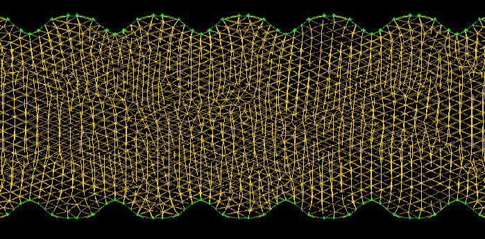
59 Inlet b a Flow direction Figure 26: Schematic of rough microchannel having channel separation = 550 µm, roughness pitch = 150 µm, and roughness height = 50 µm Figure 27: Meshed geometry of rough microchannel having channel separation = 550 µm, roughness pitch = 150 µm, and roughness height = 50 µm 43
60 created in Figure 24. Tet/Hybrid T-Grid meshing scheme is used and conformance of mesh spacing is carried out employing a grid independence plot. In a similar way, Figures 26 and 27 shows a different roughness geometry model and its mesh generation respectively with channel separation as 550 µm, roughness height 50 µm, and roughness pitch 150 µm. The same Tet/Hybrid T-Grid meshing scheme is used with the lowest mesh spacing possible. For each numerical analysis, it is reported that any further reduction in mesh size does not affect the pressure and velocity profiles at various cross-sections of fully developed region. This data confirms the grid independency required to justify the accuracy of numerical model used for predicting pressure drop and Nusselt number for different configurations. All the roughness geometries with varying roughness parameters are generated in a similar fashion. Further, all the meshed geometries are imported to CFD software, FLUENT to perform numerical analysis. The Reynolds number used during the experimental testing are selected and used to calculate the inlet mass flow rate. Pressure-based solver is used to achieve steady state analysis. The flow equations are solved with a first-order upwind scheme and SIMPLE algorithm is used for simulating results. Convergence criterion for velocities, continuity, and energy equations are kept as E-6 for all the cases. 44
61 6. VALIDATION OF PROPOSED NUMERICAL CFD MODEL In this chapter, the numerical model used to predict the laminar fluid flow and thermal characteristics in microchannels are validated with some of the previous available data in the literature. The numerical model shows good agreement with the published data and therefore is further extended to generate the results for H2 boundary condition. Moreover, second section of this chapter discusses about the experimental data used to validate the numerical model for rough channels. The CFD model results are compared with the experimental data and validation to accurately predict the fluid flow and heat transfer properties in presence of roughness elements is shown Validation of Numerical Model under H2 Boundary Condition The only available data in literature for H2 boundary is published by Shah and London [17] for uniform heat flux boundary condition on all the four walls of rectangular ducts. The primary objective of the current numerical model is to validate the results obtained from numerical simulations for four wall H2 boundaries for the whole range of aspect ratio from 0.1 to 1 with the published results. Table 8 shows the fully developed Nusselt number, found by numerical simulation as well as available published data, for varying aspect ratios of 0.1, 0.25, 0.33, 0.50 and 1 with H2 boundary condition. It can be seen from the Table 8 that fully developed Nusselt number found from numerical simulation results are in good agreement within ±1.98 % as compared to Shah and London [17] data. For rectangular channels, the values of fully developed Nusselt numbers depend mainly on two factors: channels aspect ratio and wall thermal boundary conditions. In general, the most 45
62 Nusselt Number, Nu Table 8: Comparison of numerically obtained fully developed laminar flow NuH2,fd with proposed values by Shah and London [17] for 4-walls H2 condition Aspect ratio, α From Shah and London, 1971 Nu H2,fd Current Numerical work Nu - H1 Nu-T Nu H1 Nu T Nu H2, numerical Nu H2, Shah & London Nu-H2 Nu-H2 Shah & London Aspect Ratio, α = a/b Figure 28: For Rectangular Ducts - Fully developed laminar flow Nusselt numbers for NuT, NuH1, & NuH2 and validation of numerical model used commonly used thermal boundary conditions in literature are T, H1 and H2. Figure 28 shows the comparison of results obtained for rectangular ducts for fully developed Nusselt numbers for different thermal boundary conditions: Nu T (constant wall temperature), Nu H1 (constant 46
63 circumferential wall temperature, uniform axial heat flux) and Nu H2 (constant wall heat flux, circumferentially and axially). The plot shows that the numerical model used to predict Nu H2 for four walls with varying aspect ratio in current work follows the same trend as predicted by the published data of Shah and London [17]. Moreover, it can be observed that H1 and T thermal boundary conditions tend to follow exponential graph with increase in aspect ratios, whereas there is a significant change in thermal behavior under H2 boundary condition. As seen in figure, for rectangular channels with varying aspect ratios, the H2 boundary condition follows a linear trend. Also, the values of fully developed Nusselt number are very close to each other for the whole range of aspect ratio under H2 boundary condition Validation of Numerical Model for Rough Microchannels Previous experimental data used for validation In order to study the effects of surface roughness on fluid flow and friction factor in microchannels, an extensive experimental data set was generated by Wagner and Kandlikar [47]. Structured sinusoidal roughness elements were fabricated on opposed rectangular channel walls to predict the effect of roughness pitch and height on pressure drop along the channel length. The author observed that as the hydraulic diameter decreases, the experimental friction factor increases and becomes more pronounce for tall and closely spaced roughness elements. In current work, same experimental data set was utilized for comparison and validation of proposed numerical model to predict the effects of surface roughness on pressure drop in microchannels. The dataset used for numerical scheme were obtained from data generated in previous work [47]. The test species used for experimentation were measured under laser 47

64 confocal microscope to locate roughness height and roughness pitch accurately as shown in Figure 29. Figure 29: Laser confocal microscope image of roughness elements and profiles of sinusoidal roughness elements [47] LabView software was used for recording the flow rate and pressure at inlet, outlet and along the length of microchannel. The data was further processed and values of friction factors were calculated for given set of test matrix. Figure 30 explains the assembly of the whole test-set-up used to perform experiments to measure fluid flow and heat transfer data in presence of surface roughness on channel walls with variable gap. The intensive experimental details and results obtained for pressure drop in presence of roughness elements are presented in a publication by Wagner [47]. 48
 (b)")
 Integrated test piece with")

 Assemble of test")

65 Sinusoidal Roughness Elements etched on microchannels (a) (b) Outlet Inlet (c) (d) Figure 30 (a) Integrated test piece with support block, (b) Original image of sinusoidal roughness elements etched on channel wall, (c) Assemble of test set-up, and (d) Workbench along with the experimental test set-up assembly [47] 49
66 Table 9 shows the channel geometries used for validating proposed numerical model. There are four smooth channel geometries and two geometries with surface roughness on opposed rectangular channel walls selected to show validation of numerical model. The values for constricted flow parameters are used to calculate pressure in rough microchannels. As seen in Table 9, the usage of constricted parameters makes significant difference in values of aspect ratio and hydraulic diameters for channels with roughness elements. The controlling parameters that are used to define the channel geometries were mainly channel separation, channel width, roughness height and roughness pitch. The channel width and channel length for all the cases in Table 8 are kept as 12.7 mm and approximately mm respectively. As discussed earlier, two roughness geometries were used to validate the proposed numerical scheme. Table 9 summarizes the detailed geometry parameters used for generating smooth and rough rectangular microchannels. Table 9: Test Matrix used for validating numerical model with experimental dataset a (µm) λ (µm) ε (µm) α α cf D h (µm) D h,cf (µm) Case I: Smooth Channels N/A N/A Case II: Rough Channels
67 6.2.2 Validation of numerical model in presence of roughness elements The different models are generated and meshed using pre-solver software, GAMBIT. Further, the meshed geometries were numerically simulated with prescribed boundary conditions using a CFD software tool, FLUENT. The pressure data along the length of microchannel is extracted from the converged simulated models. Later on, the pressure drop is calculated and once the pressure drop achieves linearity along the length of a channel, a fully developed region is assumed to be achieved. Also, hydrodynamic entrance lengths are calculated for each case and made sure that the values for fully developed pressure drop are obtained at a length greater than L h. The fully developed friction factors are then calculated from the numerical simulated pressure drop data. All the cases are solved with a Reynolds number in a range of laminar flow for microchannels. Four smooth geometries and two rough geometries are selected from experimental data of Wagner [47] to compare and validate the current numerical model. The comparison can rate the accuracy of numerical model to predict the effects of fluid flow in microchannels with and without roughness elements. The smooth channels used for experimentation are of smaller aspect ratios and are selected in order to check the accuracy of proposed numerical model to work for even very low aspect ratios. In case of rough channels, the numerical cases are solved on the basis of constricted flow parameters and the resultant numerical fully developed laminar friction factor (f fd,cf, num ) are compared with the experimental friction factor (f fd, cf, expt ) for validating current numerical model. Case I: Smooth Channels Table 10 shows the results for smooth rectangular microchannels tested for channel separation of 100 µm, 400 µm, 550 µm, and 750 µm. For each case, pressure drop data along the 51
68 length of a microchannel obtained from FLUENT simulations were in well agreement with the measured experimental pressure drop data. This shows the conformity of the numerical model to accurately predict the fully developed friction factor in microchannels for lower aspect ratios. As discussed in earlier section 4.2, the Equation (27) is used to calculate the numerical friction factor values for smooth channels, where pressure drop value is obtained from FLUENT simulations. Boundary conditions and geometric parameters were maintained exactly the same as experimental data [47] to show better comparison. Hence, the Reynolds number for each smooth channel varied as seen in Table 10. Table 10: Comparison of fully developed laminar friction factor for smooth channels Case I: Smooth Channels a (µm) α (=a/b) Re f theory f expt [47] f num % Error expt-num As discussed in literature, the fluid flow characteristic seems to deviate for microscale and macroscale channels. Therefore, the numerical results are also compared with friction factor values obtained using conventional theory (using Eq. 19 of Section 4.2) for smooth channels. The values of fully developed friction factor are higher as compared to conventional theory approach except for a case having extremely low aspect ratio of The numerical data for smooth channels are found in good agreement with experimental data [47]. For smooth narrow 52
69 rectangular channels, the percentage deviation of numerical model with experimental data is less than 2.58%. Case II: Rough Channels The roughness geometries were numerically simulated using the same numerical scheme with constricted flow parameters. Table 11 shows the Reynolds number used for each simulation which is utilized from experimental data set. Two roughness cases with varying roughness pitch as 150 µm and 250 µm are simulated for validation of numerical code. As discussed in Section 4.2, Equation (28) is used to calculate fully developed laminar friction factor values for both experimental and numerical cases. The numerically simulated results show good agreement with the experimental data as shown in Table 11. The percentage errors calculated are approximately within 3% of uncertainty. This shows the successful validation of current numerical model for predicting the effects fluid flow in presence of roughness elements and possesses a potential to estimate heat transfer enhancement. In conclusion, the numerical model is extended to estimate hydrodynamic and thermal characteristics of minichannels and microchannels in presence of roughness elements. The smooth rectangular geometries are tested again for two-opposed wall H2 boundary condition with hydraulic diameters varying from 198 µm to 1416 µm. As seen earlier, the numerical model is validated with experimental data [47] and the percentage deviation was less than 2.58% for smooth rectangular microchannels. Also, the fully developed friction factor values are found higher as compared to conventional theory. The constricted flow parameters are further used to simulate cases with structured sinusoidal surface 53
70 roughness elements on channel walls. The numerical simulation for two roughness geometries (λ = 150 µm and 250 µm) showed very good agreement with experiments as well. The percentage error for rough microchannels is found to be less than 6.33%. Table 11: Comparison of fully developed laminar friction factor for rough channels using constricted flow parameters Case II: Rough Channels a (µm) α (=a/b) α cf (=a/b) λ (µm) Re f cf, expt f cf, num % Error exptnum The numerical scheme is thereby developed to provide better understanding and insight of transport processes at microscale level. The proposed numerical model can be used to accurately predict the effects of roughness parameters such as roughness height, roughness pitch and channel separation on transport phenomena in minichannels and microchannels. 54
71 7. RESULTS AND DISCUSSIONS This chapter discusses in detail the results obtained for fully developed Nusselt number for rectangular microchannels under H2 boundary condition. Firstly, the dataset is generated for all the different heating wall configuration subjected to constant heat flux H2 condition. Also, the effects of entrance type on heat transfer in microchannels is explained. This chapter also includes the generalized correlation to estimate fully developed laminar Nusselt number as a function of channel aspect ratio. The second part of the chapter mainly discusses the accuracy of the current numerical model to predict the pressure drop and heat transfer coefficient at microscale level in presence of surface roughness elements Generated Dataset for Rectangular Microchannels under H2 Boundary Condition Initially the simulations are performed for H2 boundary conditions on all four walls for different aspect ratios from 0.1 to 1. The results of fully developed Nusselt number are then compared with the values reported by Shah and London [17]. Further simulations are performed on all the possible cases of wall boundary conditions; four wall, three wall, two opposed wall, one wall and two adjacent wall for different aspect ratios for two different cases of abrupt and smooth entrance types. The results from these simulations are used to predict the effect of entrance type on thermally developing entrance region in rectangular microchannels. Large data set is generated for thermally developing Nusselt number for three-wall, two-wall, one-wall and two adjacent wall uniform heat flux boundary condition (H2) for whole range of aspect ratio varying from 0.1 to 10. The aspect ratio is defined as a/b for all the numerical simulations under H2 boundary condition with different heated channel wall configurations. 55
72 Nusselt Number, Nu Effects of entrance type on Nusselt number Figure 31 and figure 32 are the plots showing variation in Nusselt number along the length of the microchannel having uniform heat flux on four-walls and three-walls respectively. These cases are plotted only for the first 10 mm length of rectangular microchannel in order to see the effect of entrance headers on Nusselt number. Results for microchannels with and without abrupt entrance are shown for two different aspect ratios of 0.1 and 0.5. From these plots it can be seen that the entrance type does not have any significant impact on the Nusselt number in the entrance region of thermally developing flow. Similar results are observed for two wall and one wall H2 boundary conditions as well Abrupt entrance type (AR=0.1) Abrupt entrance type (AR=0.5) Smooth entrance type (AR=0.1) Smooth entrance type (AR=0.5) Length along the microchannel, x (mm) Figure 31: Plot of Nusselt number along the length of the microchannel having smooth and abrupt entrance with H2 boundary condition on all the four walls. 56
73 Nusselt Number, Nu Abrupt entrance type (AR=0.1) Abrupt entrance type (AR=0.5) Smooth entrance type (AR=0.1) Smooth entrance type (AR=0.5) Length along the microchannel, x (mm) Figure 32: Plot of Nusselt number along the length of the microchannel having smooth and abrupt entrance with H2 boundary condition on three walls Results for H2 boundary condition The next step in this work is to generate large data set for Nusselt number in thermally developing flow with H2 boundary condition. Figure are the plots showing Nusselt number along the non-dimensional length of a microchannel with uniform heat flux on three walls, two opposed walls, one wall and two adjacent walls respectively. As expected, the graphs show that the Nusselt number is very high at the beginning of the entrance region of microchannel and thereafter decreases exponentially to the fully developed Nusselt number. The fully developed Nusselt numbers obtained for four walls and three walls H2 boundary condition seem to have an linear increasing trend with an increase in the channel aspect ratio. A similar trend is observed in the plots of Shah and London [17] for the four wall cases. This trend 57
74 Nusselt number, Nu is also similar to that observed by investigators for the three wall case for H1 and T boundary conditions with only difference in the values of the fully developed Nusselt number [48]. Moreover, for the three wall H2 boundary condition, the values of fully developed Nusselt number converge and are approximately around 3 for all aspect ratios from 0.1 to 10. Also, the trend of Nusselt number along the non- dimensional axial length of microchannels for the three wall H2 condition is similar to that observed for the four wall cases (both cases follow linear trend with different slopes). The difference in the results of fully developed laminar flow Nusselt number in the three wall uniform heat flux H2 boundary condition as compared to H1 and T thermal boundary conditions are only due to the fact that the longer side (i.e. wall 1) is kept adiabatic in current work as compared to shorter wall kept as adiabatic in previous work. In fact, all the cases with varying wall boundary conditions tend to follow the same pattern with respect AR=0.25 AR=0.33 AR=0.5 AR = 0.6 AR = 0.75 AR = Non-dimensional axial length, x* Figure 33: Local Nusselt number as a function of non-dimensional length and channel aspect ratio for three-wall H2 boundary condition 58
75 Nusselt Number, Nu Nusselt number, Nu AR=0.25 AR=0.33 AR=0.5 AR = 0.6 AR = 0.75 AR = Non-dimensional axial length, x* Figure 34: Local Nusselt number as a function of non-dimensional length and channel aspect ratio for two-opposed wall H2 boundary condition AR=0.25 AR=0.33 AR=0.5 AR=0.6 AR = 0.75 AR = Non-dimensional axial length, x* Figure 35: Local Nusselt number as a function of non-dimensional length and channel aspect ratio for one-wall H2 boundary condition 59
76 Nusselt Number, Nu AR=0.25 AR=0.33 AR=0.5 AR=0.6 AR = Non-dimensional axial length, x* Figure 36: Local Nusselt number as a function of non-dimensional length and channel aspect ratio for two-adjacent wall H2 boundary condition to the dimensionless thermal length. The values of Nusselt number did not seem to vary much for the whole range of channel aspect ratio for the three wall H2 boundary condition as seen in Figure 33 compared to other cases subjected to H2 boundary condition. Figures 34 and 35 show local Nusselt number along the non-dimensional length of rectangular microchannel for the two wall and one wall H2-constant wall heat flux boundary condition. The fully developed Nusselt numbers for both cases have a decreasing trend with an increase in the aspect ratio. This trend is similar to the results observed for H1 and T boundary conditions for the two wall and one wall transferring heat [48]. Similar trend is observed for the case of two adjacent heated walls of a rectangular microchannel as shown in Figure 36. In order to study the heat transfer effects in the entrance region of microchannels, Nusselt number is plotted as a function of non dimensional length x* for all the cases. Figures shows result for rectangular microchannels for the entire range of aspect ratios investigated 60
77 under H2 boundary condition for one or more walls transferring heat. From these figures, it can be seen that a larger channel aspect ratio will have a larger dimensionless thermal entrance length x th, and its value decreases with simultaneous decrease in aspect ratio. The results show that the value of Nusselt number starts high and decreases rapidly along the length of the microchannel Generated numerical data set for fully developed laminar flow Nusselt number under H2 boundary condition Table 11 below represents the values of fully developed laminar flow Nusselt number found from the results of numerical simulations with different heated wall configurations for rectangular microchannels for the entire range of aspect ratios. Data sets are generated for constant wall heat flux, both circumferentially and axially, by performing CFD computations for wide range of cases. The numerical values for fully developed Nusselt number for all the possible cases can prove to be a good tool to provide an estimation of heat transfer coefficient used for the design and optimization of microchannel heat sinks and other major microfluidic devices. 61
78 Table 12: Rectangular Ducts: NuH2,fd for fully developed laminar flow, for one or more walls transferring heat under uniform heat flux H2 boundary condition Fully Developed Laminar Flow Nusselt Number, Nu H2,fd Aspect ratio, α (a/b) a 4-wall BC 3-wall BC 2-opposite wall BC 1-wall BC a a a a 2-adjacent wall BC b b b b b Figure 37 represents the approximation of fully developed Nusselt number with one or more walls transferring heat. Based on the predicted results, Nu H2 approximation was performed to estimate the correlation with respect to channel aspect ratio, within 0.8%. The correlations were curve-fitted to the results simulated with a correlation coefficient (R 2 1) by the following: For four walls H2 boundary condition 0.1 α 1, Nu H2,fd,4walls = α (Eq. 29) 62
79 For three walls H2 boundary condition 0.1 α 10 Nu H2,fd,3walls = α α α α α α (Eq. 30) For two opposite walls H2 boundary condition 0.1 α 10, Nu H2,fd,2walls = α α α α α α (Eq. 31) For one wall H2 boundary condition 0.1 α 10, Nu H2,fd,1 wall = α α α α α α (Eq. 32) For two adjacent walls H2 boundary condition 0.1 α 1, Nu H2,fd,2 adj walls = α α α α (Eq. 33) All the above correlations for fully developed Nusselt number have a very small average residual and an excellent correlation coefficient. The correlations are generalized using a statistical analysis tool and regression analysis is performed with an extremely low residual tolerance over a large number of numerically simulated values. Figure 35 depicts the trend followed by each boundary condition with varying microchannel aspect ratios. 63
80 8 7 Case - 1 Case - 2 b a 4-wall H2 3-wall H2 adiabatic wall Case opp wall H2 Nusselt Number, Nu fd, H Case - 4 Case wall H2 2- adj wall H α = a/b α = b/a Aspect Ratio, α Figure 37: Rectangular Ducts: NuH2,fd for fully developed laminar flow, for one or more walls transferring heat under uniform heat flux H2 boundary condition 7.2. Numerical Study of Roughness Elements in Microchannels Numerical simulations are employed for assessing structured roughness effects in microchannels through the use of commercial CFD software. A numerical simulation of flow through microchannels with structured sinusoidal roughness elements along the channel walls is conducted. The effects of various geometric parameters such as roughness height, roughness pitch, and channel separation on the friction factor and heat transfer coefficient are investigated 64
81 in this work. As discussed in earlier sections, the constricted flow parameters are used to analyze the effects of transport processes in presence of surface roughness. The numerical model used for smooth channels under H2 boundary condition is extended to predict the laminar flow properties for rough channels. The accuracy of this numerical model to evaluate the pressure drop is found to be in good agreement with the previous experimental results. In order to check the predictability of the numerical model, sinusoidal roughness pattern with varying roughness height (ε), roughness pitch (λ), and channel separation (a) are generated Data Analysis For each roughness geometry, Reynolds number is kept at 100 in order to confirm laminar flow regime. All the geometric parameters are calculated using constricted flow theory for rough channels. The physical properties involved in these analysis, such as density and dynamic viscosity, are determined from the properties of water at STP conditions. Rest of the parameters such as average velocity, friction factor and heat transfer are calculated using the velocity field and average temperature difference between the wall and fluid obtained from numerical simulations. Figure 38 below shows the temperature variation of wall and fluid along the length of channel for one of the roughness geometry having channel separation as 550 µm, roughness pitch as 250 µm, and roughness height as 50 µm. The figure shows that the heat transfer coefficient is very high at the entrance region and progressively becomes constant, i.e. when fully developed laminar flow is achieved. Based on the temperature difference (ΔT) in figure, heat transfer coefficient can be estimated which is used to calculate fully developed Nusselt 65
82 Temperature (K) number. As seen from the figure, the average wall temperature profile seems to have a larger bandwidth compared to mean bulk temperature along the length of a microchannel. Figure 39 shows the same temperature profile for roughness geometry for the first 25 mm length of channel. It can be seen that the wall temperature varies on the basis of roughness profile along the channel. Also, the analysis in a single roughness element shows that the temperature at the extreme bottom node of the roughness element has the highest temperature whereas the extreme top node has the lowest temperature. This is due to the fact that the extreme top node comes in direct contact with the bulk mean temperature and it has more tendency to dissipate heat to the fluid domain Twall avg Tfluid avg ΔT Length of microchannel (mm) Figure 38: Temperature variation for the roughness geometry having a = 550 µm, λ = 250 µm, and ε = 50 µm 66
83 Temperature (K) Temperature (K) Twall Tfluid avg Length of microchannel (mm) Twall Tfluid avg Length of microchannel (mm) Figure 39: Analysis of temperature variation for the roughness geometry having a = 550 µm, λ = 250 µm, and ε = 50 µm 67
84 The sinusoidal roughness elements provides flow modifications which increases heat transfer compared to smooth channels at the expense of increase in pressure head. Moreover, the temperature variation for sinusoidal roughness geometries is observed in both directions, along the length as well as the width of the channels. Therefore, it becomes important to properly analyze the average wall temperature for roughness geometries to estimate accurate heat transfer from the system. As discussed above, the wall temperature varies along the length of the microchannel due to flow modifications caused by the fluid following the path of sinusoidal roughness pattern. Figure 40 shows the schematic of roughness profiles for a geometry having channel separation as 550 µm, roughness pitch as 250 µm, and roughness height as 50 µm. Figure 41 shows the variation of wall temperature along the length of microchannel for same geometry. T wall at tip T wall at mean line T wall at floor profile (Base) Figure 40: Geometric representation of wall temperature variations along the length of the channel for roughness geometry having a = 550 µm, λ = 250 µm, and ε = 50 µm Initially, in order to calculate the average wall temperature, several node points are computed along a single roughness element. Thereafter, the mean of all the different nodes is calculated to estimate average wall temperature. Also, as defined in earlier section (Section 4.2), the wall 68
85 Wall Temperature (K) temperature is measured a distance of an average maximum profile peak height (R pm ) to estimate average wall temperature based on theory. Both the values of average wall temperature tend to lie over each other with a maximum deviation of 0.03%. 323 Temperature profile T wall averaged Length of microchannel (mm) Figure 41: Wall temperature variation along the length of channel for roughness geometry having a = 550 µm, λ = 250 µm, and ε = 50 µm Therefore, to simplify the calculations, the average wall temperature is measured at the main profile mean line as shown in Figure 40. The data points computed for wall temperature in Figure 41 are in a fully developed laminar region. Also, the corresponding average wall temperature shown in Figure 41 follows a linear increasing trend as expected. In a similar way, the heat transfer coefficients for all the roughness geometries are estimated based on the wall temperature computed at a distance of averaged maximum profile peak height (R pm ). 69

86 Figure 42 shows the flow direction of water along the length of the microchannel having a width of 12.7 mm. Figure 43 represents single roughness element of the same geometry. As discussed in earlier chapters that temperature varies along the width of the smooth channels and five-nodes method is used to average wall temperature of the heated wall. Moreover, maximum temperature is observed at the corners and minimum at the center line of the smooth channel wall subjected under H2 boundary condition. Flow Direction Width = 12.7 mm Figure 42: Geometric representation of flow over the roughness geometry having a = 550 µm, λ = 250 µm, and ε = 50 µm In case of roughness geometries, constant heat flux H2 boundary condition is applied on the two opposite channel walls having surface roughness. Similar temperature variation is also observed along the width of the rough channel with maximum temperature at the corners and minimum at center of the channel wall. Figure 44 shows the temperature variation along the width of rough microchannel at 90 mm axial distance (along the width highlighted with orange 70

87 Wall Temperature (K) color line in Figure 43). Again, the same five-nodes averaged method is used to calculate average wall temperature along the width of the microchannel for different roughness geometry. Figure 43: Single roughness element for the roughness geometry having a = 550 µm, λ = 250 µm, and ε = 50 µm Twall along the width of channel Along the width of channel (mm) Figure 44: Wall temperature variation along the width of the channel for roughness geometry having a = 550 µm, λ = 250 µm, and ε = 50 µm 71
88 Effects of Roughness Parameters The pressure drop and heat transfer data for microchannels with surface roughness are obtained by numerically solving the continuity and energy equations using commercial CFD code. In this current work, roughness elements are configured as structured sinusoidal pattern along the channel walls. Using structured roughness features on surfaces will provide better understanding of different roughness parameters such as roughness height, roughness pitch, and channel separation on pressure drop and heat transfer in minichannels and microchannels. As expected, roughness elements on channel walls result showed enhancement in transport behavior compared to smooth channels due to area enhancement and flow modifications Effects of Roughness Height In narrow channels, structured sinusoidal roughness elements act as small obstructions in the flow which provides mixing of fluid and aids in heat removal from the system. Figures 45, 46 and 47 show the temperature profiles along the axial length of a microchannel for three different roughness geometries with varying roughness height. The temperature profiles are shown for the first 25 mm length of microchannel as the flow becomes fully developed within that length and it follows linear trend thereafter. As seen in the figures, the channel separation and roughness pitch are kept as 550 µm and 250 µm respectively for all the three cases. The roughness height is varied from 20 µm to 100 µm. This study helps to signify the effects of roughness height on transport processes in microchannels. Also, the temperature variation is plotted by computing the wall temperatures at different locations on roughness element such as tip, base and average roughness peak height. The heat 72
89 Temperature (K) Temperature (K) Twall at y=0 (Base) Twall at y=0.004 mm (Mean) Twall at y = mm (Tip) Tfluid avg Along the length of microchannel (mm) Figure 45: Temperature variation along the length of channel for roughness geometry having a = 550 µm, λ = 250 µm, and ε = 20 µm Twall at y=0 (Base) Twall at y=0.010 mm (Mean) Twall at y = mm (Tip) Tfluid avg Along the length of microchannel (mm) Figure 46: Temperature variation along the length of channel for roughness geometry having a = 550 µm, λ = 250 µm, and ε = 50 µm 73
90 Temperature (K) Twall at y=0 (Base) Twall at y=0.020 mm (Mean) Twall at y = mm (Tip) Tfluid avg Along the length of microchannel (mm) Figure 47: Temperature variation along the length of channel for roughness geometry having a = 550 µm, λ = 250 µm, and ε = 100 µm transfer coefficient and fully developed laminar Nusselt number are estimated by considering the temperature profile at the main profile mean line as shown in figures above. It can be observed from the Figures that the wall temperature at the base of roughness element is maximum whereas it is the lowest at the tip of the roughness element. Moreover, the temperature profile at a distance of average roughness peak height (R pm ) lies between the maximum roughness peak height and floor profile mean line. In all the three cases, constant heat flux H2 boundary condition is applied on the two opposite roughness walls which is calculated based on the constricted flow parameters. As seen from the figures, in a fully developed laminar flow region, the temperature difference between the wall and fluid tends to increase with increase in roughness height. This corresponds to the 74
91 decrease in the heat transfer coefficient with increment in the roughness height from 20 µm to 100 µm. This results are observed due to the fact that the roughness height grows taller keeping the channel separation and roughness pitch constant. Basically, the majority of the fluid flows through the gap between the roughness peaks created on opposite channel walls. The function of the roughness element is to enhance the mixing of the fluid flowing through the channel. As the roughness element height increases, its functionality decreases. Table 13 shows the effect of roughness height on the fully developed Nusselt number for rough microchannels. The constricted Nusselt number is calculated based on constant heat flux on two rough surfaces rather than projected area. The heat transfer coefficient decreases with the corresponding increase in the structured roughness height. This is due to the decrease in the magnitude of the effective hydraulic diameter which is calculated using the constricted flow parameters as seen in the table below. Table 13: Rough Channels: Nu H2,fd for fully developed laminar flow with varying roughness height a (μm ) λ (μm) ε (μm) b (mm) D h (μm) D h, cf (μm) Fully Developed Nusselt number, Nu H2, fd Constricted Fully Developed Nusselt number, Nu H2, fd, cf Figures 48 and 49 show the velocity contour and velocity vectors for a rough geometry having channel separation of 550 µm, roughness pitch of 250 µm, and roughness height of 50 µm. The figures show continuous streamlines and no formation of vortices beneath the 75

92 Figure 48: Velocity contours for roughness geometry having a = 550 µm, λ = 250 µm, and ε = 50 µm Figure 49: Velocity vectors for roughness geometry having a = 550 µm, λ = 250 µm, and ε = 50 µm 76

93 Figure 50: Velocity vectors near structured sinusoidal roughness elements for roughness geometry having a = 550 µm, λ = 250 µm, and ε = 50 µm roughness elements. Similar contours are observed for all the different roughness geometries and none of the roughness geometry showed formation of vortices. This is due to the fact that roughness are generated as smooth structured sinusoidal rather than having sharp corners in roughness elements which enhances heat transfer high but at the expense of pressure head. The enhancement observed in the current work is purely due to flow modifications in presence of roughness elements. Therefore, roughness can be considered as an important feature in design and operation of micro-systems to enhance heat transfer properties Effects of Roughness Pitch To study the effects of roughness pitch on fluid flow and heat transfer properties, three geometries are selected with varying pitch as 150 µm, 250 µm, and 400 µm respectively. Also, 77
Using Computational Fluid Dynamics And Analysis Of Microchannel Heat Sink
 International Journal of Engineering Inventions e-issn: 2278-7461, p-issn: 2319-6491 Volume 4, Issue 12 [Aug. 2015] PP: 67-74 Using Computational Fluid Dynamics And Analysis Of Microchannel Heat Sink M.
CFD Analysis of Forced Convection Flow and Heat Transfer in Semi-Circular Cross-Sectioned Micro-Channel
 CFD Analysis of Forced Convection Flow and Heat Transfer in Semi-Circular Cross-Sectioned Micro-Channel *1 Hüseyin Kaya, 2 Kamil Arslan 1 Bartın University, Mechanical Engineering Department, Bartın, Turkey
Numerical Investigation of Effects of Ramification Length and Angle on Pressure Drop and Heat Transfer in a Ramified Microchannel
 Journal of Applied Fluid Mechanics, Vol. 9, No. 2, pp. 767-772, 2016. Available online at www.jafmonline.net, ISSN 1735-3572, EISSN 1735-3645. Numerical Investigation of Effects of Ramification Length
Comparison of heat transfer characteristics of liquid coolants in forced convection cooling in a micro heat sink
 Nivesh Agrawal et al. / IJAIR ISSN: 78-7844 Comparison of heat transfer characteristics of liquid coolants in forced convection cooling in a micro heat sink Mr.Nivesh Agrawal #1 Mr.Mahesh Dewangan * #1
Experimental and numerical evaluation of single phase adiabatic flows in plain and enhanced microchannels
 Rochester Institute of Technology RIT Scholar Works Theses Thesis/Dissertation Collections 11-1-2007 Experimental and numerical evaluation of single phase adiabatic flows in plain and enhanced microchannels
Laminar flow heat transfer studies in a twisted square duct for constant wall heat flux boundary condition
 Sādhanā Vol. 40, Part 2, April 2015, pp. 467 485. c Indian Academy of Sciences Laminar flow heat transfer studies in a twisted square duct for constant wall heat flux boundary condition RAMBIR BHADOURIYA,
Effect of developing flow and thermal regime on momentum and heat transfer in micro-scale heat sink
 International Journal of Heat and Mass Transfer 50 (2007) 3100 3114 www.elsevier.com/locate/ijhmt Effect of developing flow and thermal regime on momentum and heat transfer in micro-scale heat sink Y.
Numerical simulation of steady state and transient heat transfer in microchannels
 University of South Florida Scholar Commons Graduate Theses and Dissertations Graduate School 2007 Numerical simulation of steady state and transient heat transfer in microchannels Phaninder Injeti University
Numerical simulation of fluid flow in a monolithic exchanger related to high temperature and high pressure operating conditions
 Advanced Computational Methods in Heat Transfer X 25 Numerical simulation of fluid flow in a monolithic exchanger related to high temperature and high pressure operating conditions F. Selimovic & B. Sundén
A Computational Fluid Dynamics Investigation of Solar Air Heater Duct Provided with Inclined Circular Ribs as Artificial Roughness
 Bonfring International Journal of Industrial Engineering and Management Science, Vol. 4, No. 3, August 2014 115 A Computational Fluid Dynamics Investigation of Solar Air Heater Duct Provided with Inclined
FLOW DISTRIBUTION ANALYSIS IN A HEAT EXCHANGER WITH DIFFERENT HEADER CONFIGURATIONS
 FLOW DISTRIBUTION ANALYSIS IN A HEAT EXCHANGER WITH DIFFERENT HEADER CONFIGURATIONS M. M. Matheswaran 1, S. Karthikeyan 2 and N. Rajiv Kumar 2 1 Department of Mechanical Engineering, Jansons Institute
Enhanced MicroChannel Heat Transfer in Macro- Geometry using Conventional Fabrication Approach
 Journal of Physics: Conference Series PAPER OPEN ACCESS Enhanced MicroChannel Heat Transfer in Macro- Geometry using Conventional Fabrication Approach To cite this article: KT Ooi and AL Goh 2016 J. Phys.:
Effects of structured roughness on fluid flow at the microscale level
 Rochester Institute of Technology RIT Scholar Works Theses Thesis/Dissertation Collections 11-1-010 Effects of structured roughness on fluid flow at the microscale level Rebecca Noelani Wagner Follow this
Numerical Investigation of Laminar Flow in Micro-tubes with Designed Surface Roughness
 Numerical Investigation of Laminar Flow in Micro-tubes with Designed Surface Roughness Abdel-Fattah Mahrous 1,2, Saad Mahmoud 1, Raya K. Al-dadah 1, *, Ahmed M. Elsayed 1 * Corresponding author: Tel.:
A REVIEW OF HEAT TRANSFER AND LAMINAR FLOW IN A MICROCHANNEL
 A REVIEW OF HEAT TRANSFER AND LAMINAR FLOW IN A MICROCHANNEL Mohit Kumar 1, Rajesh kumar 2 1 Department of Mechanical Engineering, NIT Kurukshetra, India 2 Assistant Professor, Department of Mechanical
CFD Analysis on Flow Through Plate Fin Heat Exchangers with Perforations
 CFD Analysis on Flow Through Plate Fin Heat Exchangers with Perforations 1 Ganapathi Harish, 2 C.Mahesh, 3 K.Siva Krishna 1 M.Tech in Thermal Engineering, Mechanical Department, V.R Siddhartha Engineering
NUMERICAL INVESTIGATION OF COUNTER FLOW ISOSCELES RIGHT TRIANGULAR MICROCHANNEL HEAT EXCHANGER
 International Journal of Mechanical Engineering and Technology IJMET) Volume 8, Issue 1, January 217, pp. 81 87, Article ID: IJMET_8_1_9 Available online at http://www.iaeme.com/ijmet/issues.asp?jtype=ijmet&vtype=8&itype=1
Inherent benefits in microscale fractal-like devices for enhanced transport phenomena
 Inherent benefits in microscale fractal-like devices for enhanced transport phenomena D. Pence & K. Enfield Department of Mechanical Engineering, Oregon State University, USA Abstract Heat sinks with fractal-like
Thermal & Hydraulic Characteristics of Single phase flow in Mini-channel for Electronic cooling Review
 Thermal & Hydraulic Characteristics of Single phase flow in Mini-channel for Electronic cooling Review Keyur Thakkar 1, Krishna Kumar 2, Harshit Trivedi 3 Professor, Dept. of Mechanical Engineering, Babaria
COMBINED NUMERICAL OPTIMIZATION AND CONSTRUCTAL THEORY FOR THE DESIGN OF MICRO-CHANNEL HEAT SINKS
 COMBINED NUMERICAL OPTIMIZATION AND CONSTRUCTAL THEORY FOR THE DESIGN OF MICRO-CHANNEL HEAT SINKS by Bello-Ochende T*., Meyer J.P., Ighalo F.U *Author for correspondence Department of Mechanical and Aeronautical
Numerical analysis of fluid flow and heat transfer in 2D sinusoidal wavy channel
 Numerical analysis of fluid flow and heat transfer in 2D sinusoidal wavy channel Arunanshu Chakravarty 1* 1 CTU in Prague, Faculty of Mechanical Engineering, Department of Process Engineering,Technická
NUMERICAL STUDY OF MICROSCALE HEAT SINKS USING DIFFERENT SHAPES & FLUIDS. Vipender Singh Negi CSIR-CSIO Chandigarh Govt. Of INDIA
 NUMERICAL STUDY OF MICROSCALE HEAT SINKS USING DIFFERENT SHAPES & FLUIDS Vipender Singh Negi CSIR-CSIO Chandigarh Govt. Of INDIA Thermal Solution 1 Liquid cooling Spray impingements/liquid immersion/microchannel
Experimental Analysis of Wire Sandwiched Micro Heat Pipes
 Experimental Analysis of Wire Sandwiched Micro Heat Pipes Rag, R. L. Department of Mechanical Engineering, John Cox Memorial CSI Institute of Technology, Thiruvananthapuram 695 011, India Abstract Micro
Experimental Investigation of Single-Phase Friction Factor and Heat Transfer inside the Horizontal Internally Micro-Fin Tubes.
 Experimental Investigation of Single-Phase Friction Factor and Heat Transfer inside the Horizontal Internally Micro-Fin Tubes by Sun Cheong Master of Science in Electromechanical Engineering 2013 Faculty
Investigation of the Flow Characteristics of Titanium - Oxide - Water Nanofluid in Microchannel with Circular Cross Section
 American Journal of Nano Research and Applications 2017; 5(6): 102-109 http://www.sciencepublishinggroup.com/j/nano doi: 10.11648/j.nano.20170506.14 ISSN: 2575-3754 (Print); ISSN: 2575-3738 (Online) Investigation
LAMINAR FLOW FORCED CONVECTION HEAT TRANSFER BEHAVIOR OF PHASE CHANGE MATERIAL FLUID IN STRAIGHT AND STAGGERED PIN MICROCHANNELS.
 LAMINAR FLOW FORCED CONVECTION HEAT TRANSFER BEHAVIOR OF PHASE CHANGE MATERIAL FLUID IN STRAIGHT AND STAGGERED PIN MICROCHANNELS A Thesis by SATYANARAYANA KONDLE Submitted to the Office of Graduate Studies
THERMAL PERFORMANCE COMPARISON BETWEEN MICROCHANNEL AND ROUND TUBE HEAT EXCHANGERS OZKAN EMRE OZDEMIR. Bachelor of Science in Aerospace Engineering
 THERMAL PERFORMANCE COMPARISON BETWEEN MICROCHANNEL AND ROUND TUBE HEAT EXCHANGERS By OZKAN EMRE OZDEMIR Bachelor of Science in Aerospace Engineering Middle East Technical University Ankara, Turkey 2006
Comparative Study for Improving the Thermal and Fluid Flow Performance of Micro Channel Fin Geometries Using Numerical Simulation
 American Journal of Engineering Research (AJER) e-issn: 2320-0847 p-issn : 2320-0936 Volume-4, Issue-7, pp-73-82 www.ajer.org Research Paper Open Access Comparative Study for Improving the Thermal and
CHAPTER 7 NUMERICAL MODELLING OF A SPIRAL HEAT EXCHANGER USING CFD TECHNIQUE
 CHAPTER 7 NUMERICAL MODELLING OF A SPIRAL HEAT EXCHANGER USING CFD TECHNIQUE In this chapter, the governing equations for the proposed numerical model with discretisation methods are presented. Spiral
CFD AND CONJUGATE HEAT TRANSFER ANALYSIS OF HEAT SINKS WITH DIFFERENT FIN GEOMETRIES SUBJECTED TO FORCED CONVECTION USED IN ELECTRONICS COOLING
 CFD AND CONJUGATE HEAT TRANSFER ANALYSIS OF HEAT SINKS WITH DIFFERENT FIN GEOMETRIES SUBJECTED TO FORCED CONVECTION USED IN ELECTRONICS COOLING V. M Kulkarni 1, Basavaraj Dotihal 2 1 Professor, Thermal
Effect of Channel Size on Heat Transfer and Pressure Drop in Thin Slabs Minichannel Heat Exchanger
 Avestia Publishing International Journal of Mechanical Engineering and Mechatronics Volume 2, Issue 1, Year 214 ISSN: 1929-2724 DOI: 1.11159/ijmem.214.4 Effect of Channel Size on Heat Transfer and Pressure
ME 331 Homework Assignment #6
 ME 33 Homework Assignment #6 Problem Statement: ater at 30 o C flows through a long.85 cm diameter tube at a mass flow rate of 0.020 kg/s. Find: The mean velocity (u m ), maximum velocity (u MAX ), and
International Journal of Advanced Engineering Technology E-ISSN
 Research Article EFFECT OF ROUGHNESS ELEMENT PITCH ON HEAT TRANSFER AND FRICTION CHARACTERISTICS OF ARTIFICIALLY ROUGHENED SOLAR AIR HEATER DUCT Aman Soi*, Ranjit Singh, Brij Bhushan Address for Correspondence
Fluid Flow, Heat Transfer and Boiling in Micro-Channels
 L.P. Yarin A. Mosyak G. Hetsroni Fluid Flow, Heat Transfer and Boiling in Micro-Channels 4Q Springer 1 Introduction 1 1.1 General Overview 1 1.2 Scope and Contents of Part 1 2 1.3 Scope and Contents of
COMPUTATIONAL FLUID DYNAMICS ANALYSIS OF A V-RIB WITH GAP ROUGHENED SOLAR AIR HEATER
 THERMAL SCIENCE: Year 2018, Vol. 22, No. 2, pp. 963-972 963 COMPUTATIONAL FLUID DYNAMICS ANALYSIS OF A V-RIB WITH GAP ROUGHENED SOLAR AIR HEATER by Jitesh RANA, Anshuman SILORI, Rajesh MAITHANI *, and
TABLE OF CONTENTS CHAPTER TITLE PAGE
 v TABLE OF CONTENTS CHAPTER TITLE PAGE TABLE OF CONTENTS LIST OF TABLES LIST OF FIGURES LIST OF SYMBOLS LIST OF APPENDICES v viii ix xii xiv CHAPTER 1 INTRODUCTION 1.1 Introduction 1 1.2 Literature Review
Minhhung Doan, Thanhtrung Dang
 An Experimental Investigation on Condensation in Horizontal Microchannels Minhhung Doan, Thanhtrung Dang Department of Thermal Engineering, Hochiminh City University of Technology and Education, Vietnam
Investigation of Jet Impingement on Flat Plate Using Triangular and Trapezoid Vortex Generators
 ISSN 2395-1621 Investigation of Jet Impingement on Flat Plate Using Triangular and Trapezoid Vortex Generators #1 Sonali S Nagawade, #2 Prof. S Y Bhosale, #3 Prof. N K Chougule 1 Sonalinagawade1@gmail.com
Numerical Investigation of Air-Side Heat Transfer and Fluid Flow in a Microchannel Heat Exchanger
 Proceedings of the 2 nd World Congress on Mechanical, Chemical, and Material Engineering (MCM'16) Budapest, Hungary August 22 23, 2016 Paper No. HTFF 135 DOI: 10.11159/htff16.135 Numerical Investigation
COMPUTATIONAL ANALYSIS OF LAMINAR FORCED CONVECTION IN RECTANGULAR ENCLOSURES OF DIFFERENT ASPECT RATIOS
 HEFAT214 1 th International Conference on Heat Transfer, Fluid Mechanics and Thermodynamics 14 16 July 214 Orlando, Florida COMPUTATIONAL ANALYSIS OF LAMINAR FORCED CONVECTION IN RECTANGULAR ENCLOSURES
Numerical Study of the Three-dimensional Flow in a Flat Plate Solar Collector with Baffles
 Numerical Study of the Three-dimensional Flow in a Flat Plate Solar Collector with Baffles M.A. AMRAOUI a, K. ALIANE b a. Department of Mechanical Engineering, Faculty of Technology, University of Tlemcen,
CFD study for cross flow heat exchanger with integral finned tube
 International Journal of Scientific and Research Publications, Volume 6, Issue 6, June 2016 668 CFD study for cross flow heat exchanger with integral finned tube Zena K. Kadhim *, Muna S. Kassim **, Adel
THE EFFECTS OF LONGITUDINAL RIBS ON ENTROPY GENERATION FOR LAMINAR FORCED CONVECTION IN A MICROCHANNEL
 THE EFFECTS OF LONGITUDINAL RIBS ON ENTROPY GENERATION FOR LAMINAR FORCED CONVECTION IN A MICROCHANNEL Nader POURMAHMOUD, Hosseinali SOLTANIPOUR *1,, Iraj MIRZAEE Department of Mechanical Engineering,
1 Nik Mohamad Sharif & Normah Mohd Ghazali / Jurnal Teknologi (Sciences & Engineering) 78: 10 2 (2016) 61 68
 78: 10 2 (2016) 61 68") ik Mohamad Sharif & ormah Mohd Ghazali / Jurnal Teknologi (Sciences & Engineering) 78: 0 2 (206) 6 68 Jurnal Teknologi PERFORMACE OF A MULTI-STACK MICROCHAEL HEAT SIK ik Mohamad Sharif, ormah Mohd Ghazali
ik Mohamad Sharif & ormah Mohd Ghazali / Jurnal Teknologi (Sciences & Engineering) 78: 0 2 (206) 6 68 Jurnal Teknologi PERFORMACE OF A MULTI-STACK MICROCHAEL HEAT SIK ik Mohamad Sharif, ormah Mohd Ghazali
EXPERIMENTAL AND NUMERICAL STUDIES OF A SPIRAL PLATE HEAT EXCHANGER
 THERMAL SCIENCE: Year 2014, Vol. 18, No. 4, pp. 1355-1360 1355 EXPERIMENTAL AND NUMERICAL STUDIES OF A SPIRAL PLATE HEAT EXCHANGER by Rangasamy RAJAVEL Department of Mechanical Engineering, AMET University,
A Comparative Second Law Analysis of Microchannel Evaporator with R-134A & R-22 Refrigerants
 International Journal of Scientific & Engineering Research, Volume 3, Issue 6, June-2012 1 A Comparative Second Law Analysis of Microchannel Evaporator with R-134A & R-22 Refrigerants Suhel Khan, Dr.Suwarna
Semi-Empirical 3D Rectangular Channel Air Flow Heat Transfer and Friction Factor Correlations
 Purdue University Purdue e-pubs International Refrigeration and Air Conditioning Conference School of Mechanical Engineering 2006 Semi-Empirical 3D Rectangular Channel Air Flow Heat Transfer and Friction
Principles of Convection
 Principles of Convection Point Conduction & convection are similar both require the presence of a material medium. But convection requires the presence of fluid motion. Heat transfer through the: Solid
World Journal of Engineering Research and Technology WJERT
 wjert, 2016, Vol. 2, Issue 3, 108-119 Research Article ISSN 2454-695X Yadav et al. WJERT www.wjert.org SJIF Impact Factor: 3.419 INVESTIGATION OF AXIAL HEAT CONDUCTION FLUX IN RECTANGULAR PARALLEL FLOW
Analysis of the Cooling Design in Electrical Transformer
 Analysis of the Cooling Design in Electrical Transformer Joel de Almeida Mendes E-mail: joeldealmeidamendes@hotmail.com Abstract This work presents the application of a CFD code Fluent to simulate the
Computational Fluid Dynamics Based Analysis of Angled Rib Roughened Solar Air Heater Duct
 Research Article International Journal of Thermal Technologies ISSN 2277-4114 2013 INPRESSCO. All Rights Reserved. Available at http://inpressco.com/category/ijtt Computational Fluid Dynamics Based Analysis
IJSRD - International Journal for Scientific Research & Development Vol. 3, Issue 06, 2015 ISSN (online):
:") IJSRD - International Journal for Scientific Research & Development Vol. 3, Issue 06, 2015 ISSN (online): 2321-0613 Experimental Investigation for Enhancement of Heat Transfer in Two Pass Solar Air Heater
IJSRD - International Journal for Scientific Research & Development Vol. 3, Issue 06, 2015 ISSN (online): 2321-0613 Experimental Investigation for Enhancement of Heat Transfer in Two Pass Solar Air Heater
The Effect of Solid and Perforated Pin Fin on the Heat Transfer Performance of Finned Tube Heat Exchanger
 International Journal of Energy Engineering 2018, 8(1): 1-11 DOI: 10.5923/j.ijee.20180801.01 The Effect of Solid and Perforated Pin Fin on the Heat Transfer Performance of Finned Tube Heat Exchanger Nabil
Microchannel Heat Sink with nanofluids
 Microchannel Heat Sink with nanofluids The Summary of the PhD thesis University Politehnica Timişoara ing. Laza Ioan PhD supervisor: Prof. dr.ing. Dorin LELEA 2016 The Summary of the PhD thesis 2 The miniaturization
Effect of roughness shape on heat transfer and flow friction characteristics of solar air heater with roughened absorber plate
 Advanced Computational Methods in Heat Transfer IX 43 Effect of roughness shape on heat transfer and flow friction characteristics of solar air heater with roughened absorber plate A. Chaube 1, P. K. Sahoo
Thermo-Hydraulic performance of Internal finned tube Automobile Radiator
 Thermo-Hydraulic performance of Internal finned tube Automobile Radiator Dr.Kailash Mohapatra 1, Deepiarani Swain 2 1 Department of Mechanical Engineering, Raajdhani Engineering College, Bhubaneswar, 751017,
A CFD Simulation Study on Pressure Drop and Velocity across Single Flow Microchannel Heat Sink
 A CFD Simulation Study on Pressure Drop and Velocity across Single Flow Microchannel Heat Sink A. A. Razali *,a and A. Sadikin b Faculty of Mechanical Engineering and Manufacturing, Universiti Tun Hussein
HEAT TRANSFER THERMAL MANAGEMENT OF ELECTRONICS YOUNES SHABANY. C\ CRC Press W / Taylor Si Francis Group Boca Raton London New York
 HEAT TRANSFER THERMAL MANAGEMENT OF ELECTRONICS YOUNES SHABANY C\ CRC Press W / Taylor Si Francis Group Boca Raton London New York CRC Press is an imprint of the Taylor & Francis Group, an informa business
Lecture 30 Review of Fluid Flow and Heat Transfer
 Objectives In this lecture you will learn the following We shall summarise the principles used in fluid mechanics and heat transfer. It is assumed that the student has already been exposed to courses in
Numerical Study of Heat Transfer of Water Flow through Pipe with Property Variations. By Amjad Ali Pasha A. Mushtaq Khalid A.
 Numerical Study of Heat Transfer of Water Flow through Pipe with Property Variations By Amjad Ali Pasha A. Mushtaq Khalid A. Juhany Microchannels, with their small size and high heat dissipation capacity,
Fundamental issues, mechanisms and models of flow boiling heat transfer in microscale channels
 Fundamental issues, mechanisms and models of flow boiling heat transfer in microscale channels CHENG, Lixin and XIA, Guodong Available from Sheffield Hallam University Research Archive (SHURA) at: http://shura.shu.ac.uk/14546/
NUMERICAL HEAT TRANSFER ENHANCEMENT IN SQUARE DUCT WITH INTERNAL RIB
 NUMERICAL HEAT TRANSFER ENHANCEMENT IN SQUARE DUCT WITH INTERNAL RIB University of Technology Department Mechanical engineering Baghdad, Iraq ABSTRACT - This paper presents numerical investigation of heat
FACULTY OF CHEMICAL & ENERGY ENGINEERING FLUID MECHANICS LABORATORY TITLE OF EXPERIMENT: MINOR LOSSES IN PIPE (E4)
") FACULTY OF CHEMICAL & ENERGY ENGINEERING FLUID MECHANICS LABORATORY TITLE OF EXPERIMENT: MINOR LOSSES IN PIPE (E4) 1 1.0 Objectives The objective of this experiment is to calculate loss coefficient (K
FACULTY OF CHEMICAL & ENERGY ENGINEERING FLUID MECHANICS LABORATORY TITLE OF EXPERIMENT: MINOR LOSSES IN PIPE (E4) 1 1.0 Objectives The objective of this experiment is to calculate loss coefficient (K
Simple model for predicting microchannel heat sink performance and optimization
 Heat Mass Transfer (2012) 48:789 798 DOI 10.1007/s00231-011-0933-2 ORIGINAL Simple model for predicting microchannel heat sink performance and optimization Tsung-Hsun Tsai Reiyu Chein Received: 18 January
Australian Journal of Basic and Applied Sciences. Numerical Investigation of Flow Boiling in Double-Layer Microchannel Heat Sink
 AENSI Journals Australian Journal of Basic and Applied Sciences ISSN:1991-8178 Journal home page: www.ajbasweb.com Numerical Investigation of Flow Boiling in Double-Layer Microchannel Heat Sink Shugata
International Communications in Heat and Mass Transfer
 International Communications in Heat and Mass Transfer 39 (12) 82 86 Contents lists available at SciVerse ScienceDirect International Communications in Heat and Mass Transfer journal homepage: www.elsevier.com/locate/ichmt
Keywords: Spiral plate heat exchanger, Heat transfer, Nusselt number
 EXPERIMENTAL AND NUMERICAL STUDIES OF A SPIRAL PLATE HEAT EXCHANGER Dr.RAJAVEL RANGASAMY Professor and Head, Department of Mechanical Engineering Velammal Engineering College,Chennai -66,India Email:rajavelmech@gmail.com
EFFECT OF RIB TURBULATORS ON HEAT TRANSFER PERFORMANCE IN STATIONARY RIBBED CHANNELS ARAVIND ROHAN SAMPATH. Bachelor of Production Engineering
 EFFECT OF RIB TURBULATORS ON HEAT TRANSFER PERFORMANCE IN STATIONARY RIBBED CHANNELS ARAVIND ROHAN SAMPATH Bachelor of Production Engineering Anna University May, 2007 Submitted in partial fulfillment
Table of Contents. Foreword... xiii. Preface... xv
 Table of Contents Foreword.... xiii Preface... xv Chapter 1. Fundamental Equations, Dimensionless Numbers... 1 1.1. Fundamental equations... 1 1.1.1. Local equations... 1 1.1.2. Integral conservation equations...
CFD Analysis for Thermal Behavior of Turbulent Channel Flow of Different Geometry of Bottom Plate
 International Journal Of Engineering Research And Development e-issn: 2278-067X, p-issn: 2278-800X, www.ijerd.com Volume 13, Issue 9 (September 2017), PP.12-19 CFD Analysis for Thermal Behavior of Turbulent
PREDICTION OF MASS FLOW RATE AND PRESSURE DROP IN THE COOLANT CHANNEL OF THE TRIGA 2000 REACTOR CORE
 PREDICTION OF MASS FLOW RATE AND PRESSURE DROP IN THE COOLANT CHANNEL OF THE TRIGA 000 REACTOR CORE Efrizon Umar Center for Research and Development of Nuclear Techniques (P3TkN) ABSTRACT PREDICTION OF
Convection Heat Transfer. Introduction
 Convection Heat Transfer Reading Problems 12-1 12-8 12-40, 12-49, 12-68, 12-70, 12-87, 12-98 13-1 13-6 13-39, 13-47, 13-59 14-1 14-4 14-18, 14-24, 14-45, 14-82 Introduction Newton s Law of Cooling Controlling
Numerical investigation of entropy generation in microchannels heat sink with different shapes
 IOP Conference Series: Materials Science and Engineering PAPER OPEN ACCESS Numerical investigation of entropy eration in microchannels heat sink with different shapes To cite this article: A A Alfaryjat
Piping Systems and Flow Analysis (Chapter 3)
") Piping Systems and Flow Analysis (Chapter 3) 2 Learning Outcomes (Chapter 3) Losses in Piping Systems Major losses Minor losses Pipe Networks Pipes in series Pipes in parallel Manifolds and Distribution
Piping Systems and Flow Analysis (Chapter 3) 2 Learning Outcomes (Chapter 3) Losses in Piping Systems Major losses Minor losses Pipe Networks Pipes in series Pipes in parallel Manifolds and Distribution
Chapter 3 NATURAL CONVECTION
 Fundamentals of Thermal-Fluid Sciences, 3rd Edition Yunus A. Cengel, Robert H. Turner, John M. Cimbala McGraw-Hill, 2008 Chapter 3 NATURAL CONVECTION Mehmet Kanoglu Copyright The McGraw-Hill Companies,
Chemical and Biomolecular Engineering 150A Transport Processes Spring Semester 2017
 Chemical and Biomolecular Engineering 150A Transport Processes Spring Semester 2017 Objective: Text: To introduce the basic concepts of fluid mechanics and heat transfer necessary for solution of engineering
Single phase thermohydraulic performance analysis of microchannel flow geometry for direct chip cooling
 Rochester Institute of Technology RIT Scholar Works Theses Thesis/Dissertation Collections 2004 Single phase thermohydraulic performance analysis of microchannel flow geometry for direct chip cooling Harshal
InterPACKICNMM
 Proceedings of the ASME 215 International Conference and Exhibition on Packaging and Integration of Electronic and Photonic Microsystems and ASME 215 International Conference on Nanochannels, Microchannels,
Numerical Investigation of The Convective Heat Transfer Enhancement in Coiled Tubes
 Numerical Investigation of The Convective Heat Transfer Enhancement in Coiled Tubes Luca Cattani* 1 1 Department of Industrial Engineering - University of Parma Parco Area delle Scienze 181/A I-43124 Parma,
Fluid Mechanics Theory I
 Fluid Mechanics Theory I Last Class: 1. Introduction 2. MicroTAS or Lab on a Chip 3. Microfluidics Length Scale 4. Fundamentals 5. Different Aspects of Microfluidcs Today s Contents: 1. Introduction to
Thermo-Hydraulic Performance of a Roughened Square Duct Having Inclined Ribs with a Gap on Two Opposite Walls
 International Journal of Engineering Research and Development e-issn: 2278-067X, p-issn: 2278-800X, www.ijerd.com Volume 7, Issue 10 (July 2013), PP. 55-63 Thermo-Hydraulic Performance of a Roughened Square
Experimental Investigation of Heat Transfer Characteristics on a Gas-to- Gas Parallel Flow Microchannel Heat Exchanger
 The Open Transport Phenomena Journal, 2010, 2, 1-8 1 Open Access Experimental Investigation of Heat Transfer Characteristics on a Gas-to- Gas Parallel Flow Microchannel Heat Exchanger Kohei Koyama* and
CONVECTIVE HEAT TRANSFER
 CONVECTIVE HEAT TRANSFER Mohammad Goharkhah Department of Mechanical Engineering, Sahand Unversity of Technology, Tabriz, Iran CHAPTER 4 HEAT TRANSFER IN CHANNEL FLOW BASIC CONCEPTS BASIC CONCEPTS Laminar
STUDY OF MOTOR OIL COOLING AT LOW REYNOLDS NUMBER IN MULTI-PORT NARROW CHANNELS
 University of Windsor Scholarship at UWindsor Electronic Theses and Dissertations 2012 STUDY OF MOTOR OIL COOLING AT LOW REYNOLDS NUMBER IN MULTI-PORT NARROW CHANNELS Mohammed Saadi University of Windsor
Internal Forced Convection. Copyright The McGraw-Hill Companies, Inc. Permission required for reproduction or display.
 Internal Forced Convection Copyright The McGraw-Hill Companies, Inc. Permission required for reproduction or display. Introduction Pipe circular cross section. Duct noncircular cross section. Tubes small-diameter
Heat transfer coefficient of near boiling single phase flow with propane in horizontal circular micro channel
 IOP Conference Series: Earth and Environmental Science PAPER OPEN ACCESS Heat transfer coefficient of near boiling single phase flow with propane in horizontal circular micro channel To cite this article:
Single-Phase Modeling in Microchannel with Piranha Pin Fin
 Single-Phase Modeling in Microchannel with Piranha Pin Fin Xiangfei YU *1, Corey Woodcock 1, Yoav Peles 2, Joel Plawsky 1 1. Rensselaer Polytechnic Institute, Mechanical, Aerospace, and Nuclear Engineering,
EXPERIMENTAL INVESTIGATION OF THE HEAT TRANSFER IN A HORIZONTAL MINI-TUBE WITH THREE DIFFERENT INLET CONFIGURATIONS
 Proceedings of the 2nd Thermal and Fluid Engineering Conference, TFEC2017 4th International Workshop on Heat Transfer, IWHT2017 April 2-5, 2017, Las Vegas, NV, USA TFEC-IWHT2017-17541 EXPERIMENTAL INVESTIGATION
Heat Transfer Enhancement of Solar Air Heater By Using Artificial Roughness double inclined ribs
 Heat Transfer Enhancement of Solar Air Heater By Using Artificial Roughness double inclined ribs Faisal mujib¹, Ravindra mohan² ¹Research Scholar, ²Assistant Professor, Mechanical Engineering Dept. IES
ENHANCED HEAT TRANSFER CHARACTERISTICS OF CONJUGATED AIR JET IMPINGEMENT ON A FINNED HEAT SINK
 ENANCED EAT TRANSFER CARACTERISTICS OF CONJUGATED AIR JET IMPINGEMENT ON A FINNED EAT SINK Shuxia QIU a, Peng XU a,*, Liping GENG b, Arun S. MUJUMDAR c, Zhouting JIANG a, Jinghua YANG a a College of Science,
Flow characteristics of ethanol-methanol mixture through a parallel micro-channels
 IOSR Journal of Engineering (IOSRJEN) e-issn: 50-30, p-issn: 78-879, Volume, Issue (November 0), PP 36-4 Flow characteristics of ethanol-methanol mixture through a parallel micro-channels R. Kalaivanan
International Journal of Heat and Mass Transfer
 International Journal of Heat and Mass Transfer 54 (2011) 1441 1447 Contents lists available at ScienceDirect International Journal of Heat and Mass Transfer journal homepage: www.elsevier.com/locate/ijhmt
Exergy Analysis of Solar Air Collector Having W Shaped Artificial Roughness
 Advances in Materials Science and Mechanical Engineering Research Volume 1, Number 1 (2015), pp. 25-32 International Research Publication House http://www.irphouse.com Exergy Analysis of Solar Air Collector
International Journal of Scientific & Engineering Research, Volume 6, Issue 5, May ISSN
 International Journal of Scientific & Engineering Research, Volume 6, Issue 5, May-2015 28 CFD BASED HEAT TRANSFER ANALYSIS OF SOLAR AIR HEATER DUCT PROVIDED WITH ARTIFICIAL ROUGHNESS Vivek Rao, Dr. Ajay
Comparative study of Different Geometry of Ribs for roughness on absorber plate of Solar Air Heater -A Review
 Comparative study of Different Geometry of Ribs for roughness on absorber plate of Solar Air Heater -A Review Gulshan Singh Baghel 1, Dr. A R Jaurker 2 1. Student, M.E. (Heat Power engineering), Jabalpur
Heat Transfer Convection
 Heat ransfer Convection Previous lectures conduction: heat transfer without fluid motion oday (textbook nearly 00 pages) Convection: heat transfer with fluid motion Research methods different Natural Convection
Introduction to Heat and Mass Transfer. Week 14
 Introduction to Heat and Mass Transfer Week 14 Next Topic Internal Flow» Velocity Boundary Layer Development» Thermal Boundary Layer Development» Energy Balance Velocity Boundary Layer Development Velocity
Analysis of Heat Transfer Parameters in Microchannel Fluid Flow
 Analysis Heat Transfer Parameters in Microchannel Fluid Flow Amandeep Singh Wadhwa Department Mechanical Engineering,University Institute Engineering and Technology,Punjab University,Chandigarh,Email:
PHYSICAL MECHANISM OF CONVECTION
 Tue 8:54:24 AM Slide Nr. 0 of 33 Slides PHYSICAL MECHANISM OF CONVECTION Heat transfer through a fluid is by convection in the presence of bulk fluid motion and by conduction in the absence of it. Chapter
Estimation of Heat Transfer in Internally Micro Finned Tube
 Page9 Estimation of Heat Transfer in Internally Micro Finned Tube B. Usha Rani* and P.S. Kishore** * M.E Thermal, Department of Mechanical Engineering, College of Engineering (A), Andhra University **Professor,