School and Training Course on Dense Magnetized Plasma as a Source of Ionizing Radiations, their Diagnostics and Applications
|
|
|
- Douglas Tucker
- 5 years ago
- Views:
Transcription


1 School and Training Course on Dense Magnetized Plasma as a Source of Ionizing 8-12 October 2012 Plasma Focus Numerical Experiments - Scaling Properties to Scaling Laws S. Lee INTI International University, Nilai Malaysia Institute for Plasma Focus Studies, Chadstone, VIC 3148 Australia University of Malaya, Kuala Lumpur Malaysia
2 School and Training Course on Dense Magnetized Plasma as a Source of Ionizing 8-12 October 2012, ICTP, Trieste Plasma Focus Numerical Experiments- Scaling Properties to Scaling Laws S Lee 1,2,3 & S H Saw 1,2 INTI International University, Nilai, Malaysia Institute for Plasma Focus Studies, Chadstone, VIC 3148, Australia University of Malaya, Kuala Lumpur, Malaysia leesing@optusnet.com.au sorheoh.saw@newinti.edu.my
3 Our Modelling Experimental based Utility prioritised To cover the whole process- from lift-off, to axial, to all the radial sub-phases; and recently to post-focussed phase which is important for advanced materials deposition and damage simulation
4 Priority of Basis Energy consistent for the total process and each part of the process Mass consistent Charge consistent Connected to the reality of experiments
5 Priority of Results Applicable to all Mather-type PF machines, existing and hypothetical Current Waveform accuracy Dynamics in agreement with experiments Consistency of Energy distribution Realistic Yields of neutrons, SXR, other radiations; Ions and Plasma Stream; in conformity with experiments Widest Scaling of the yields; all gases Insightful definition of scaling properties Design of new devices; e.g. High V & Current-Step Design of new experiments; radiative cooling and collapse
6 Basis, modelling, results and applications of the Model code
7 Numerical Experiments Range of activities using the code is wide Not theoretical Not simulation The preferred description is: Numerical Experiments
8 Plasma Focus Numerical Experiments- Scaling Properties & Scaling Laws Outline of talk: Numerical experiments are used to deduce scaling properties of the PF. Numerical experiments are used to deduce scaling laws for neutrons and neon SXR. We connect the scaling laws as a development from the scaling properties. A Global Scaling Law for neutron yields as a function of storage energies is derived from numerical experiments combined with measured data showing a deterioration of scaling due to the dynamic resistance of the axial phase. A by-product of the numerical experiments are diagnostic reference points.
9 The Model code- Comprehensive Numerical Experiments To model the plasma dynamics & plasma conditions Then obtain insights into scaling properties Then scaling laws Critical to the approach: Model is linked to physical reality by the current waveform
10 The Plasma Focus 1/2 Plasma focus: small fusion device, complements international efforts to build fusion reactor Multi-radiation device - x-rays, particle beams and fusion neutrons Neutrons for fusion studies Soft XR applications include microelectronics lithography and micro-machining Large range of device-from J to thousands of kj Experiments-dynamics, radiation, instabilities and nonlinear phenomena
11 The Plasma Focus 2/2 Phases Axial Phase Radial
12 The 5-phases of the Model code Includes electrodynamical- and radiation- coupled equations to portray the REGULAR mechanisms of the: axial (phase 1) radial inward shock (phase 2) radial RS (phase 3) slow compression radiation phase (phase 4) the expanded axial post-pinch phase (phase 5) Crucial technique of the code: Current Fitting
13 The Model
14 The Axial Phase- two coupled equations (1) & (2)
 density over mass density power")
15 The characteristic speed and The Speed Factor S= Current (linear) density over mass density power half
16 Radial Phase- Four coupled equations (7) to (10)
17 Radial characteristic speed & Speed Factor
18 S= Current (linear) density over mass density power half
19 Speed scaling: ratio of radial/axial speed
20 Integration scheme
21 The 5-phases of the Model code axial (phase 1) 2 coupled equations radial inward shock (phase 2) 4 coupled eqns radial RS (phase 3)- 3 coupled equns namely: RS moving outwards, piston moving inwards & circuit slow compression radiation phase (phase 4) : Radiation & heat coupled eqn of motion coupled to circuit eqn; Bennett for temperature & Spitzer for heat; Plasma self-absorption included (P. Lee & Khatak) Anomalous resistive phase (Phase 4a) 3 fitting regimes the expanded axial post-pinch phase (phase 5)
22 Crucial technique of the code: Current Fitting: The computed current is fitted to the measured; modifying the computation at each step of the fitting; thus connecting the physics-based model with the reality of the experiment Generated
23 Philosophy of Current fitting 1/3 The current trace of the focus is the best indicators of gross performance. The exact time profile of the current trace is governed by the bank parameters, the focus tube geometry and the operational parameters. It depends on the mass swept-up and drive current fractions and their variations. These parameters determine the dynamics, specifically the axial and radial speeds which in turn affect the profile and magnitudes of the current. There are many underlying mechanisms (see following slide) which are not simply modeled. The detailed current profile is influenced by these effects and during the pinch phase also reflects the Joule heating and radiative yields. At the end of the pinch phase the profile reflects the sudden transition from a constricted pinch to a large column flow. Thus the current powers all dynamic, electrodynamic, thermodynamic and radiation processes in the various phases. Conversely all dynamic, electrodynamic, thermodynamic and radiation processes in the various phases affect the current. The current waveform contains information on all the dynamic, electrodynamic, thermodynamic and radiation processes that occur in the various phases. This explains the importance attached to matching the computed total current trace to the measured total current trace in the procedure adopted by the Lee model code. Once matched, the fitted model parameters assure that computation proceeds with all physical mechanisms accounted for, in the gross energy & mass balance sense.
24 Philosophy of Current fitting 3/3 All inaccurate model effects are accounted for by the fitting: Known effects that might deviate from our modelling include: 1. Geometrical, including our assumed geometry 2. Our assumed structures and distributions 3. Mass shedding & current sheet CS porosity 4. Current shedding, fragmenting, leakage & inclination 5. Non uniformity & inhomogeneity of CS and plasma; boundary layer effects 6. Radiation & thermodynamics 7. Ejection of mass caused by necking curvatures Once current-fitted, also unspecified and unknown effect are also accounted for in terms of energy and mass.
25 Philosophy of Current fitting 2/3 So we relate to reality through a measured current trace computed current waveform is adjusted to fit measured current waveform Adjustment by model parameters fm, fc, fmr, fcr; account for all factors affecting mass flow and force field flows not specifically modelled including all KNOWN and UNKNOWN effects. When adjustments are completed so that the computed waveform fit the measured waveform, the computed system is energetically and mass-wise equivalent to the real system.
26 Insights Limitation to Pinch Current and Yields- S Lee & S H Saw: Appl Phys Letts. 92 (2008) Note also: M Trunk Plasma Physics, 17, 237 (1975) Neutron Yield Scaling-sub kj to 1 MJ-J Fusion Energy 27 (2008) S Lee & S H Saw- multi-mj- PPCF 50 (2008) S Lee Neon Soft x-ray Scaling- PPCF 51 (2009) S Lee, S H Saw, P Lee, R S Rawat Neutron Yield Saturation- Appl Phys Letts. 95 (2009) S Lee Simple explanation of major obstruction to progress Benchmarking Fast Ion Beams and scaling laws-s Lee, S H Saw
27 From Measured Current Waveform to Modelling for Diagnostics Procedure to operate the code: Step 1: Configure the specific plasma focus, Input: Bank parameters, L 0, C 0 and stray circuit resistance r 0 ; Tube parameters b, a and z 0 and Operational parameters V 0 and P 0 and the fill gas
28 Step 2: Fitting the computed current waveform to the measured waveform-(connecting with reality) A measured discharge current I total waveform for the specific plasma focus is required The code is run successively. At each run the computed I total waveform is fitted to the measured I total waveform by varying model parameters f m, f c, f mr and f cr one by one, one step for each run, until computed waveform agrees with measured waveform. 1. Fitting static inductance Lo and stray resistance ro. This is done by matching current risetimes and current amplitudes 2. The 5-Point Fit: First, the axial model factors f m, f c are adjusted (fitted) until (1) computed rising slope of the I total trace and (2) the rounding off of the peak current as well as (3) the peak current itself are in reasonable (typically very good) fit with the measured I total trace. Next, adjust (fit) the radial phase model factors f mr and f cr until - (4) the computed slope and - (5) the depth of the dip agree with the measured I total waveform.
29 Example of current fitting: Given any plasma focus : e.g. PF1000 Bank parameters: L0=20nH (nominal) ; C 0 =1332 µf; r 0 =not given (try 1 m Tube parameters: b=16 cm, a=11.55 cm, z 0 =60cm Operation parameters: V 0 =27kV, P 0 =3.5 Torr in D The UPFLF (Lee code) is configured (by keying figures into the configuration panel on the EXCEL sheet) as the PF1000
30 Step I.2. Configure the code as the PF1000 using given parameters; note those parameters (in red) that are not certain or guessed Start Configuration Given: L 0 nh C 0 uf b cm a cm z 0 cm r 0 mω fm fc fmr fcr V 0 kv P 0 Torr MW A Atom-molecule
31 1000 kj machine Big Plasma Focus
32 Fire the PF1000, compare computed current waveform with measured current waveform
33 1. Use typical trial values of f m, f c, f mr, f cr ; use given value of L 0 and guess value of r 0 ; Result: computed current risetime too short; need to increase L 0 - risetime~l 0 0.5

34 2. Increase L 0 to 25 nh, computed risetime increases, fits better; but not enough. Need to increase L 0 further
35 3. Increase L 0 to 30 nh, fits better. Next note computed current too high; that suggests to increase r 0

36 4. Increase r 0 to 3 mω, that drops the current and the fit is better. Try increase r 0 further
37 5. Increase r 0 to 5 mω; fit of current rise slope is now quite good. For the moment fit of L 0 and r 0 looks OK; although may need to come back later. Next note radial phase comes far too early; that means axial speed too fast. To reduce axial speed, increase axial mass factor f m


38 6. Increase axial f m to 0.1; note improvement to fit; but axial speed still too fast. Need to increase f m further. Note, also that reducing the speed increases the current

39 7. Increase f m to 0.13, note that computed radial phase starts later and fit is better; but still not enough. Also note that current has gone higher- due to the reduced loading because of lower speed. Note: lower speed leads to higher current. Suggest increase f m, which will slow axial speed and increase current further; so at same time need to increase r 0
40 8. Increase f m to 0.14 at same time increase r 0 to 6 mω; fit is now better but current still too high; the computed radial start point is still slightly early; but if we increase r 0 the current will drop and the speed will reduce. So suggest increase r 0 slightly.

 agrees very well with the")
41 9. Increase r 0 to 6.3 mω. Note that the computed current has dropped enough for the rising slope (particularly the top part of the rising slope) and the flattened top to agree very well. Also the computed current dip start (roll off) agrees very well with the measured current dip start. Thus L 0 and r 0 fitted; also f m is fitted.


42 10 Next, to fit the radial phase. Note last slide computed slope of dip is much too steep than measured dip slope. This means that the computed speed is too high. To reduce the radial speed, increase f mr ; try Note improvement; the computed slope is now less steep and agrees better with the measured; need to increase f mr further.

43 11. Increase f mr to 0.34; Note that the average slope of the computed current dip is now very close to the average slope of the measured current dip. Note 5 points of agreement: 1. Rising slope; 2. Topping profil;e 3. Top and Ipeak; 4.start of current dip; 5.slope of dip; and 6. Bottom of dip. The fit is good overall.


44 Fitting PF kV-adjusting model parameters until computed current waveform matches measured (after getting L 0 correct)

45 PF1000 fitted results

46 Summary: the 5-point fit 1/2
47 Once fitted: model is energy-wise & mass-wise equivalent to the physical situation 2/2 All dynamics, electrodynamics, radiation, plasma properties and neutron yields are realistically simulated; so that the code output of these quantities may be used as reference points for diagnostics

48 Scaling Properties 3 kj machine Small Plasma Focus 1000 kj machine Big Plasma Focus

49 Comparing large and small PF s- Dimensions and lifetimes- putting shadowgraphs side-by-side, almost same scale Anode radius 1 cm 11.6 cm Pinch Radius: 1mm 12mm Pinch length: 8mm 90mm Lifetime ~10ns order of ~100 ns
50 Focus Pinch T, dimensions & lifetime with anode radius a Scaling properties-mainly radial phase Dimensions and lifetime scales as the anode radius a. rmin/a (almost constant at ) zmax/a (almost constant at 1.5) Pinch duration narrow range 8-14 ns/cm of a Tpinch is measure of energy per unit mass. Quite remarkable that this energy density varies so little (factor of 5) over such a large range of device energy (factor of 1000).

51 Scaling Properties: Pinch Dimensions & Duration: Compare D & Ne (Lee, Kudowa 1998, Cairo 2003)
52 Rule-of-thumb scaling properties, (subject to minor variations caused primarily by the variation in c=b/a) over whole range of device Axial phase energy density (per unit mass) constant Radial phase energy density (per unit mass) constant Pinch radius ratio constant Pinch length ratio constant Pinch duration per unit anode radius constant
53 Computation of Neutron yield (1/2) Adapted from Beam-target neutron generating mechanism (ref Gribkov et al) A beam of fast deuteron ions close to the anode interacts with the hot dense plasma of the focus pinch column produces the fusion neutrons Given by: Y b-t = C n n i I pinch2 z p2 (ln(b/r p ))σ /U 0.5 where n i = ion density b = cathode radius, r p = radius of the plasma pinch column with length z p, σ = cross-section of the D-D fusion reaction, n- branch, U= beam energy, and C n = calibration constant
54 More detailed description: The beam-target yield is written in the form Y b-t ~ n b n i (r p2 z p ) (v b ) where nb is the number of beam ions per unit plasma volume, ni is the ion density, rp is the radius of the plasma pinch with length zp, is the cross section of the D D fusion reaction, n branch,18 vb is the beam ion speed, and is the beamtarget interaction time assumed proportional to the confinement time of the plasma column. Total beam energy is estimated17 as proportional to LpIpinch 2 a measure of the pinch inductance energy, Lp being the focus pinch inductance. Thus, the number of beam ions is Nb ~ LpIpinch 2 v b 2 and nb is Nb divided by the focus pinch volume. Note that Lplnb rpzp, that4 rpzp, and that vbu1 2 where U is the disruption-caused diode voltage.17 Here, b is the cathode radius.we also assume reasonably that U is proportional to Vmax, the maximum voltage induced by the current sheet collapsing radially toward the axis.
55 Computation of Neutron yield (2/2) Note: The D-D cross-section is sensitive to the beam energy in the range kv; so it is necessary to use the appropriate range of beam energy to compute σ. The code computes induced voltages (due to current motion inductive effects) V max of the order of only kv. However it is known, from experiments that the ion energy responsible for the beam-target neutrons is in the range keV, and for smaller lower-voltage machines the relevant energy could be lower at 30-60keV. In line with experimental observations the D-D cross section σ is reasonably obtained by using U= 3V max. ThemodelusesavalueofC n =2.7x10 7 obtained by calibrating the yield at an experimental point of 0.5 MA.


56 Computation of Neon SXR yield (1/2) Neon SXR energy generated Y SXR = Neon line radiation Q L Q L calculated from: where : Z n = atomic number, n i = number density, Z = effective charge number, r p = pinch radius, z f = pinch length and T = temperature Q L is obtained by integrating over the pinch duration.
57 Computation of Neon SXR yield (2/2) Note: The SXR yield is the reduced quantity of generated energy after plasma self-absorption which depends primarily on density and temperature The model computes the volumetric plasma self-absorption factor A derived from the photonic excitation number M which is a function of the Z n,n i,zandt. In our range of operation the numerical experiments show that the self absorption is not significant. Liu Mahe (1999) first pointed out that a temperature around 300 ev is optimum for SXR production. Shan Bing s (2000) subsequent work and our experience through numerical experiments suggest that around 2x10 6 K (below 200 ev) or even a little lower could be better. Hence for SXR scaling there is an optimum small range of temperatures (T window). [ ev]
58 Scaling laws for neutrons from numerical experiments over a range of energies from 10kJ to 25 MJ (1/4) To study the neutrons emitted by PF1000-like bank energies from 10kJ to 25 MJ. 1) Apply the Lee model code to fit a measured current trace of the PF1000: C 0 = 1332 μf, V 0 =27kV,P 0 =3.5torrD 2 ; b = 16 cm, a = cm or c=1.39; z 0 = 60 cm; external (or static) inductance L 0 = 33.5 nh and; damping factor RESF= 1.22 (or stray resistance r 0 =6.1 mω). 2) Apply the Lee code over a range of C 0 ranging from 14 µf (8.5 kj) to µf (24 MJ): Voltage, V 0 =35kV;P 0 = 10 torr deuterium; RESF = 1.22; ratio c=b/a is For each C 0, anode length z 0 is varied to find the optimum z 0. For each z 0, anode radius a 0 is varied to get end axial speed of 10 cm/µs.
59 Scaling laws for neutrons from numerical experiments over a range of energies from 10kJ to 25 MJ (2/4) Fitted model parameters : f m = 0.13, f c = 0.7, f mr = 0.35 and f cr =0.65. Computed current trace agrees very well with measured trace through all the phases: axial and radial, right down to the bottom of the current dip indicating the end of the pinch phase as shown below. PF1000: C 0 = 1332 μf; V 0 = 27 kv; P 0 = 3.5 Torr D 2 ; b = 16 cm; a = cm; z 0 = 60 cm; L 0 = 33.5 nh; r 0 = 6.1 mω or RESF=1.22.
60 Scaling laws for neutrons from numerical experiments over a range of energies from 10kJ to 25 MJ (3/4) Voltage, V 0 = 35 kv; P 0 = 10 torr deuterium; RESF = 1.22; ratio c=b/a is Numerical experiments: C 0 ranging from 14 µf(8.5 kj) to µf (24 MJ) For each C 0, anode length z 0 is varied to find the optimum z 0. For each z 0, anode radius a 0 is varied to get end axial speed of 10 cm/µs. Yn scaling changes: Y n ~E at tens of kj Y n ~E at the highest energies (up to 25MJ)
61 Scaling laws for neutrons from numerical experiments over a range of energies from 10kJ to 25 MJ (4/4) Scaling of Y n with I peak and I pinch : Y n =3.2x10 11 I pinch 4.5 and Y n =1.8x10 10 I peak 3.8 where I peak = ( )MA and I pinch = ( )MA. Log Yn, Y n in Y n vs I pinch (higher line), Y n vs I peak (lower line) y = x 4.5 y = 7x10-12 x Log I, I in ka
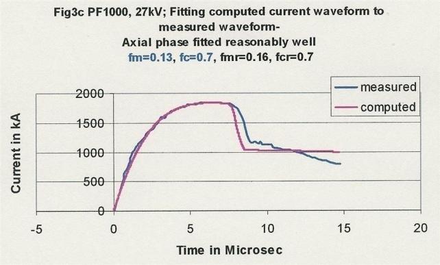
62 Scaling laws for neon SXR from numerical experiments over a range of energies from 0.2 kj to 1 MJ (1/4) To study the neon SXR emitted by a modern fast bank energies from 0.2 kj to 1 MJ. Apply the Lee model code to a proposed modern fast plasma focus machine: 1) With optimised values: c=b/a =1.5 V 0 = 20 kv L 0 = 30 nh RESF = 0.1 Model parameters : f m =0.06, f c =0.7, f mr =0.16, f cr =0.7. 2) For C 0 varying from 1 μf (0.2 kj) to 5000 μf (1MJ): For each C 0, vary P 0, z 0, and a 0 to find the optimum Y sxr
63 Scaling laws for neon SXR from numerical experiments over a range of energies from 0.2 kj to 1 MJ (2/4) Computed Total Current versus Time For L 0 = 30nH; V 0 = 20 kv; C 0 = 30 uf; RESF = 0.1; c=1.5 Model parameters : f m = 0.06, f c = 0.7, f mr =0.16, f cr = 0.7 Optimised a=2.29cm; b=3.43 cm and z 0 =5.2 cm.
64 Scaling laws for neon SXR from numerical experiments over a range of energies from 0.2 kj to 1 MJ (3/4) Y sxr scales as: E at low energies in the sub kj to several kj region. E at high energies towards 1MJ.
65 Scaling laws for neon SXR from numerical experiments over a range of energies from 0.2 kj to 1 MJ (4/4) Scaling with currents Y sxr ~I peak 3.2 ( MA) and Y sxr ~I pinch 3.6 ( MA) Black data points with fixed parameters RESF=0.1; c=1.5; L 0 =30nH; V 0 =20 kv and model parameters f m =0.06, f c =0.7, f mr =0.16, f cr =0.7. White data points are for specific machines with different values for the parameters :c, L 0, V 0 etc.
66 Summary-Scaling Laws (1/2) The scaling laws obtained (at optimized condition) for Neutrons: Y n ~E at tens of kj to Y n ~E at the highest energies (up to 25MJ) Y n =3.2x10 11 Ipinch 4.5 ( MA) Y n =1.8x10 10 Ipeak 3.8 ( MA)
67 Summary-Scaling Laws (2/2) The scaling laws obtained (at optimized condition) for neon SXR: Ysxr~E0 1.6 at low energies Ysxr~E0 0.8 towards 1 MJ Ysxr~Ipeak 3.2 ( MA) and Ysxr~Ipinch 3.6 ( MA)
68 Global scaling law, combining experimental and numerical data- Yn scaling, numerical experiments from 0.4 kj to 25 MJ (solid line), compared to measurements compiled from publications (squares) from 0.4 kj to 1 MJ. What causes the deterioration of Yield scaling?
69 What causes current scaling deterioration and eventual saturation? 1/3 The axial speed loads the discharge circuit with a dynamic resistance The same axial speed over the range of devices means the same dynamic resistance constituting a load impedance DR0 Small PF s : have larger generator impedance Z0=[L0/C0]^0.5 than DR0 As energy is increased by increasing C0, generator impedance Z0 drops
70 What causes current scaling deterioration and eventual saturation? 2/3 At E0 of kj and tens of kj the discharge circuit is dominated by Z0 Hence as E0 increases, I~C0-0.5 At the level typically of 100 kj, Z0 has dropped to the level of DR0; circuit is now no longer dominated by Z0; and current scaling deviates from I~C0-0.5, beginning of current scaling deterioration. At MJ levels and above, the circuit becomes dominated by DR0, current saturates
71 Deterioration and eventual saturation of Ipeak as capacitor energy increases Axial phase dynamic resistance causes current scaling deterioration as E0 increases
72 In numerical experiments we showed: Yn~Ipinch 4.5 Yn~Ipeak 3.8 Hence deterioration of scaling of Ipeak will lead to deterioration of scaling of Yn.
73 What causes current scaling deterioration and eventual saturation? 3/3 Analysis using the Lee model code has thus shown that the constancy of the dynamic resistance causes the current scaling deterioration resulting in the deterioration of the neutron yield and eventual saturation. This puts the global scaling law for neutron yield on a firmer footing
74 Connecting the scaling properties with the global scaling law (1/3) At kj level; experimentally observedyn~e0 2 Ideal scaling at the highest convenient voltage V0: I~ V0 /Z0 at low energy level where Z0 dominates leading to I~E0 0.5 for optimised low L0 and Yn~I0 4 At higher energy around 100kJ, Z0 domination ends and current deterioration starts
75 Connecting the scaling properties with the global scaling law (2/3) Lower current increase than the ideal leads to lower increase in anode radius a This leads to lower increase in pinch volume and pinch duration Which leads to lower increase in yield
76 Connecting the scaling properties with the global scaling law (3/3) Finally at very high energies, current hardly increases anymore with further increase in energy Theanode radius should not be increased anymore; only its length should be increased Hence pinch volume and duration also will not increase anymore. Thus we relate yield scaling deterioration & yield saturation to scaling properties, the fundamental one being the dynamic resistance.
77 Plasma Focus Numerical Experiments- Scaling Properties & Scaling Laws Conclusions We have used numerical experiments to deduce scaling properties of the plasma focus We have used numerical experiments to deduce scaling laws for neutrons and neon SXR. We have connected the scaling laws as a development from the scaling properties. A Global Scaling Law for neutron yields as a function of storage energies has also been derived from numerical experiments combined with measured data. A by-product of the numerical experiments are diagnostic reference points.
78 Papers from Lee model code 1\2 S Lee and S H Saw, Pinch current limitation effect in plasma focus, Appl. Phys. Lett. 92, 2008, S Lee and S H Saw, Neutron scaling laws from numerical experiments, J Fusion Energy 27, 2008, pp S Lee, P Lee, S H Saw and R S Rawat, Numerical experiments on plasma focus pinch current limitation, Plasma Phys. Control. Fusion 50, 2008, (8pp). S Lee, S H Saw, P C K Lee, R S Rawat and H Schmidt, Computing plasma focus pinch current from total current measurement, Appl. Phys. Lett. 92, 2008, S Lee, Current and neutron scaling for megajoule plasma focus machine, Plasma Phys. Control. Fusion 50, 2008, , (14pp). S Lee and S H Saw, Response to Comments on Pinch current limitation effect in plasma focus [Appl. Phys. Lett.94, (2009)], Appl. Phys. Leet.94, 2009, S Lee, S H Saw, L Soto, S V Springham and S P Moo, Numerical experiments on plasma focus neutron yield versus pressure compared with laboratory experiments, Plasma Phys. Control. Fusion 51, 2009, (11 pp). S H Saw, P C K Lee, R S Rawat and S Lee, Optimizing UNU/ICTP PFF Plasma Focus for Neon Soft X-ray Operation, IEEE Trans Plasma Sci, VOL. 37, NO. 7, JULY (2009) Lee S, Rawat R S, Lee P and Saw S H. Soft x-ray yield from NX2 plasma focus- correlation with plasma pinch parameters JOURNAL OF APPLIED PHYSICS 106, (2009) S Lee, S H Saw, P Lee and R S Rawat, Numerical experiments on plasma focus neon soft x- ray scaling, Plasma Physics and Controlled Fusion 51, (8pp) (2009)
79 Papers from Lee model code 2\2 M Akel, S Hawat, S Lee, Numerical Experiments on Soft X-Ray Emission Optimization of Nitrogen Plasma in 3 kj Plasma Focus Using Modified Lee Model, J Fusion Energy DOI /s First online Tuesday, May 19, 2009 M Akel, S Hawat, S Lee, Pinch Current and Soft x-ray yield limitation by numerical experiments on Nitrogen Plasma Focus, J Fusion Energy DOI /s first online 21 August 2009 S. Lee. Neutron Yield Saturation in Plasma Focus-A fundamental cause. Appl Phys Letts (2009) 95, M. Akel, Sh. Al-Hawat, S. H. Saw and S. Lee. Numerical Experiments on Oxygen Soft X- Ray Emissions from Low Energy Plasma Focus Using Lee Model J Fusion Energy DOI /s First online 22 November 2009 Sing Lee and Sor Heoh Saw Numerical Experiments providing new Insights into Plasma Focus Fusion Devices-Invited Review Paper: for Energy: special edition on Fusion Energy Energies 2010, 3, ; doi: /en published online 12 April 2010 S H Saw, S Lee, F Roy, PL Chong, V Vengadeswaran, ASM Sidik, YW Leong & A Singh- In-situ determination of the static inductance and resistance of a plasma focus capacitor bank Rev Sci Instruments (2010) 81, S H Saw and S Lee, Scaling the Plasma Focus for Fusion Energy Considerations-Int. J. Energy Res. (2010) Int. J. Energy Res. (2010) View this article online at wileyonlinelibrary.com. DOI: /er.1758 S H Sawand S Lee- Scaling laws for plasma focus machines from numerical experiments Invited paper Energy and Power Engineering, 2010, doi: /epe Published Online February 2010 (
80 Thank You
81 Numerical experiments with Bora- hands-on S H Saw Today 10 October pm-4pm (2 hrs)
82 Summary For this exercise we will fit BORA computed current waveform to match a BORA measured current waveform. From fitting the rising slope (and the risetime) of the current we obtain the static inductance L 0. From the fit of rising profile and the topping profile (including scaling the measured peak to the computed peak) we obtain the bank stray resistance r 0. From fitting the axial mass factor f m and radial mass factor f mr (where necessary also fitting current factors f c and f cr ) we obtain a good overall fit; fixing the dynamics of Bora. The final fitting produces from the code realistic results of I peak, I pinch, axial and radial dynamics and pinch properties.
83 Data for BORA is taken from the following paper: Dense Plasma Focus Bora operational at The Abdus Salam International Centre for Theoretical Physics and experiments provided with the device V.A. Gribkov, M.V. Chernyshova, A. Cicuttin, M.L. Crespo, R.A. Miklaszewski, M. Scholz, A.E. Shapiro, K. Tomaszewski, C. Tuniz
84 Data 1. Capacitance C 0 =24.4 µf (from pg 15 Table 1) 2. Chamber: cathode radius b=2.5 cm; anode radius a=1.5 cm (pg 65 Fig 62) axial length z 0 =3.5 cm (nominal) curved; will be fitted as an equivalent straight axial length 3. Current derivative trace; (from pg 84 Fig 89) - bottom most trace is used; as this is the trace with effectively the whole trace visible and distinguishable. This trace is also stated to be of a properly synchronised shot (4 PSS switches properly synchonised ) so that each trace is a proper PROFILE representation of the total circuit current.

85 Current derivative trace: (from pg 84 Fig 89)
86 Notes: 1. The current derivative trace is di/dt taken at one of the 4 PSSs. 2. Inductance (static) of bank L 0 is not given; we will fit it unambiguously from the slope of the computed current trace fitted to the measured current. 3. Stray resistance of bank is not given; we will use 0.1 of surge impedance of bank and check that this is consistent during the fitting. 4. We only have the waveform; ie the shape of the current trace taken at one of the 4 PSSs. However the model code we are using is charge- consistent. Hence once we have the current waveform correctly fitted, the computed current amplitudes are correct and may be used to calibrate the system current; we assume the shape of the current trace at the PSS that we are using is consistent with the overall current waveform.
87 Data treatment Tracing the di/dt, filtering out the high frequency noise oscillations Since we have no digital file, we trace out the di/dt Current derivative trace; (from pg 84 Fig 89 bottom-most trace) as best we could (filtering out the high frequency noise oscillations by drawing a line through the middle of the high frequency noise oscillations as judged visually. We obtained the following as shown in Figure 2.1 after an inversion to obtain the starting di/dt positive.
88 Extracted di/dt
89 Converting extracted image to digital file Then we digitized this trace using a digitizer called Engauge obtaining the digitize trace & its integration is shown in Figure 2.2 (a screen capture). Figure 2.2 Digitized di/dt trace and the integrated measured current waveform 11
90 Using the measured current trace for fittings of the computed current trace to calibrate the model code to the Bora Plasma Focus We configure the UPFL (RADPFV5.15df.xls) for Bora using the following trial configuration. Values in black: given; Values in red: trial Lo nh Co uf b cm a cm zo cm ro m massf currf massfr currfr Model Parameters Vo kv Po Torr MW A At=1 mol=2 Operational Parameters
91 In order to make the comparison meaningful we note: The computed curve and the measured curve may need to be shifted in time one relative to the other. To do that we add an amount of time (time shift) specified in Cell K1 which is varied until the start of the computed and measured traces coincide. The measured current has unknown (hence treated as arbitrary) amplitude. To make meaningful fit it is necessary to adjust the measured current amplitude to that of the computed amplitude. To do this we place a multiplying factor (multiplier) in Cell L1 which is varied until the measured amplitude is equal to the computed. Then we start the profile (shape) fitting.

92 Fitting the static inductance L 0.
93 Then fit fm, fc Then fit fmr, fcr Also fit ro
94 Final fitted configuration Lo Co b a zo ro mohm massf currf massfr currfr Model Parameters Vo Po MW A At-1 mol-2 Operatio Paramet

95 Final fit is good
96 7 Concluding Notes The inductance (55 nh fitted) is surprisingly high when compared with the predecessors PF-5M (33 nh) or NX1 (30 nh). The Designer of BORA will be able to confirm this aspect of the design in comparing with PF-5M and NX1. 2. The mass factor f m and radial mass factor f mr are unusually high indicating (a) that the solid channel of the Bora is conducive to a more efficient mass swept-up (b) and the possibility that the pressure that was actually in the chamber could be higher than about 10 mbar as stated against Fig 89; Peak circuit current Ipeak=304 ka and the neutron yield Yn= 1.9x10 8. The dynamics and some Pinch Properties are presented in the following screen capturein the next page.

97 Once fitted, the dynamics, plasma dimensions and plasma temperature and density are all outputted from the code Note that our input is just this:
98 Hands-on numerical experiment will be carried out in the next two hours
School and Training Course on Dense Magnetized Plasma as a Source of Ionizing Radiations, their Diagnostics and Applications
 2370-6 School and Training Course on Dense Magnetized Plasma as a Source of Ionizing Radiations, their Diagnostics and Applications 8-12 October 2012 Plasma Focus Numerical Experiments and BORA Sor Heoh
School and Training Course on Dense Magnetized Plasma as a Source of Ionizing Radiations, their Diagnostics and Applications
 2370-10 School and Training Course on Dense Magnetized Plasma as a Source of Ionizing 8-12 October 2012 Scaling Laws for Ion Beam number (and energy) fluence and flux S. Lee INTI International University,
Model Parameters Versus Gas Pressure in Two Different Plasma Focus Devices Operated in Argon and Neon
 DOI 10.1007/s10894-011-9414-3 ORIGINAL RESEARCH Model Parameters Versus Gas Pressure in Two Different Plasma Focus Devices Operated in Argon and Neon Sh. Al-Hawat M. Akel S. Lee S. H. Saw Ó Springer Science+Business
International Symposium on Plasma Focus in series SPFE 2013
 International Symposium on Plasma Focus in series SPFE 2013 Scaling Trends for Deuteron Beam Properties at Plasma Focus Pinch Exit S H Saw 1,2 and S Lee 1,2,3 1 INTI International University, 71800 Nilai,
Joint ICTP-IAEA Workshop on Dense Magnetized Plasma and Plasma Diagnostics
 2168-10 Joint ICTP-IAEA Workshop on Dense Magnetized Plasma and Plasma Diagnostics 15-26 November 2010 The Plasma Focus- Scaling Properties to Scaling Laws S. Lee and S. H. Saw INTI International University
Exploring the Plasma Focus-From Electrodynamics to Radiative Collapse
 Exploring the Plasma Focus-From Electrodynamics to Radiative Collapse S Lee 1.2.3 and S H Saw 1,2 1 Inti International University, Nilai Malaysia 2 IPFS, Melbourne, KL, Singapore 3 University of Malaya,
A 160 kj dual plasma focus (DuPF) for fusion-relevant materials testing and nano-materials fabrication
 for fusion-relevant materials testing and nano-materials fabrication") Plasma Science and Applications (ICPSA 213) International Journal of Modern Physics: Conference Series Vol. 32 (214) 146322 (1 pages) The Author DOI: 1.1142/S2119451463226 A 16 kj dual plasma focus (DuPF)
Plasma Science and Applications (ICPSA 213) International Journal of Modern Physics: Conference Series Vol. 32 (214) 146322 (1 pages) The Author DOI: 1.1142/S2119451463226 A 16 kj dual plasma focus (DuPF)
Compression mechanisms in the plasma focus pinch
 Compression mechanisms in the plasma focus pinch S. Lee, S. H. Saw, and Jalil Ali Citation: AIP Conference Proceedings 1824, 020001 (2017); doi: 10.1063/1.4978814 View online: http://dx.doi.org/10.1063/1.4978814
THE SLOW FOCUS MODE IN PLASMA FOCUS FOR FAST PLASMA STREAM NANO-MATERIALS FABRICATION: SELECTION OF ENERGY OF BOMBARDING PARTICLES BY PRESSURE CONTROL
 ORIGINAL RESEARCH ARTICLE OPEN ACCESS THE SLOW FOCUS MODE IN PLASMA FOCUS FOR FAST PLASMA STREAM NANO-MATERIALS FABRICATION: SELECTION OF ENERGY OF BOMBARDING PARTICLES BY PRESSURE CONTROL 1,2,3 S. Lee*,
Dependence of Plasma Focus Argon Soft X-Ray Yield on Storage Energy, Total and Pinch Currents
 DOI 10.1007/s10894-011-9445-9 ORIGINAL RESEARCH Dependence of Plasma Focus Argon Soft X-Ray Yield on Storage Energy, Total and Pinch Currents M. Akel S. Lee Ó Springer Science+Business Media, LLC 2011
Numerical experiments on the PF1000 plasma focus device operated with nitrogen and oxygen gases
 Modern Physics Letters B Vol. 31, No. 16 (217) 175167 (11 pages) c World Scientific Publishing Company DOI: 1.1142/S21798491751676 Numerical experiments on the PF1 plasma focus device operated with nitrogen
Determination of the total inductance of TPF-I
 Journal of Physics: Conference Series PAPER OPEN ACCESS Determination of the total inductance of TPF-I To cite this article: T Kunamaspakorn et al 015 J. Phys.: Conf. Ser. 611 01009 View the article online
Practical Optimization of AECS PF-2 Plasma Focus Device for Argon Soft X-ray Operation
 DOI 10.1007/s10894-011-9444-x ORIGINAL RESEARCH Practical Optimization of AECS PF-2 Plasma Focus Device for Argon Soft X-ray Operation M. Akel S. Lee Ó Springer Science+Business Media, LLC 2011 Abstract
ISSN , Volume 29, Number 3
 ISSN 164-313, Volume 29, Number 3 This article was published in the above mentioned Springer issue. The material, including all portions thereof, is protected by copyright; all rights are held exclusively
Radiative Cooling and Collapse- Comparative study of a range of gases
 Radiative Cooling and Collapse- Comparative study of a range of gases Jalil Ali 1, S H Saw 2,3, M Akel 4 and S Lee 2,3,5 1 Institute of Advanced Photonic Science, Nanotechnology Research Alliance, Universiti
Current sheet axial dynamics of 2.5 kj KSU-DPF under high pressure regime
 This is the author s final, peer-reviewed manuscript as accepted for publication. The publisher-formatted version may be available through the publisher s web site or your institution s library. Current
The plasma focus trending into the future
 INTERNATIONAL JOURNAL OF ENERGY RESEARCH Int. J. Energy Res. 2012; 36:1366 1374 Published online 9 September 2011 in Wiley Online Library (wileyonlinelibrary.com)..1918 The plasma focus trending into the
THE UNITED Nations University/International Centre for
 1276 IEEE TRANSACTIONS ON PLASMA SCIENCE, VOL. 37, NO. 7, JULY 2009 Optimizing UNU/ICTP PFF Plasma Focus for Neon Soft X-ray Operation Sor Heoh Saw, Paul Choon Keat Lee, Rajdeep Singh Rawat, and Sing Lee
Experimental Studies in a Gas Embedded Z-pinch Operating at Mega Amperes Currents
 1 IC/P7-2 Experimental Studies in a Gas Embedded Z-pinch Operating at Mega Amperes Currents L. Soto 1), C. Pavez 2), J. Moreno 1), P. Silva 1), M. Zambra 1), G. Sylvester 1) 1) Comisión Chilena de Energía
School and Training Course on Dense Magnetized Plasma as a Source of Ionizing Radiations, their Diagnostics and Applications
 2370-8 School and Training Course on Dense Magnetized Plasma as a Source of Ionizing Radiations, 8-12 October 2012 Introduction to the DPF - Machines, Applications and Properties S. Lee INTI International
S H Saw 1,2, S Lee 1,2,3
 Review of Plasma Focus Numerical Experiments S H Saw 1,2, S Lee 1,2,3 1 Nilai University, Nilai, Malaysia 2 Institute for Plasma Focus Studies, Melbourne, Australia 3 University of Malaya, Kuala Lumpur,
Development of portable neutron generators based on pinch and plasma focus discharges 1
 Development of portable neutron generators based on pinch and plasma focus discharges 1 Leopoldo Soto*, José Moreno, Patricio Silva, Cristian Pavez, Miguel Cárdenas, and Luis Altamirano Comisión Chilena
S. Lee S. H. Saw H. Hegazy Jalil Ali V. Damideh N. Fatis H. Kariri A. Khabrani A. Mahasi
 J Fusion Energ (2014) 33:235 241 DOI 10.1007/s10894-013-9658-1 ORIGINAL RESEARCH Some Generalised Characteristics of the Electro-dynamics of the Plasma Focus in Its Axial Phase: Illustrated by an Application
Developing a plasma focus research training system for the fusion energy age
 Plasma Science and Applications (ICPSA 2013) International Journal of Modern Physics: Conference Series Vol. 32 (2014) 1460313 (12 pages) The Author DOI: 10.1142/S2010194514603135 Developing a plasma focus
Design and construction of a very small repetitive plasma focus device
 Plasma Science and Applications (ICPSA 2013) International Journal of Modern Physics: Conference Series Vol. 32 (2014) 1460326 (7 pages) The Author DOI: 10.1142/S2010194514603263 Design and construction
Construction and Physics of the Dense Plasma Focus device
 2370-3 School and Training Course on Dense Magnetized Plasma as a Source of Ionizing Radiations, their Diagnostics and Applications 8-12 October 2012 Construction and Physics of the Dense Plasma Focus
Influence of gas conditions on electron temperature inside a pinch column of plasma-focus discharge
 Journal of Physics: Conference Series PAPER OPEN ACCESS Influence of gas conditions on electron temperature inside a pinch column of plasma-focus discharge To cite this article: D R Zaloga et al 218 J.
Plasma Accelerator for Detection of Hidden Objects by Using Nanosecond Impulse Neutron Inspection System (NINIS)
") Plasma Accelerator for Detection of Hidden Objects by Using Nanosecond Impulse Neutron Inspection System (NINIS) Cooperation Institute of Plasma Physics and Laser Microfusion, Warsaw, Poland Institute
Plasma Accelerator for Detection of Hidden Objects by Using Nanosecond Impulse Neutron Inspection System (NINIS) Cooperation Institute of Plasma Physics and Laser Microfusion, Warsaw, Poland Institute
D-D FUSION NEUTRONS FROM A STRONG SPHERICAL SHOCK WAVE FOCUSED ON A DEUTERIUM BUBBLE IN WATER. Dr. Michel Laberge General Fusion Inc.
 D-D FUSION NEUTRONS FROM A STRONG SPHERICAL SHOCK WAVE FOCUSED ON A DEUTERIUM BUBBLE IN WATER Dr. Michel Laberge General Fusion Inc. SONOFUSION Sonofusion is making some noise A bit short in energy, ~mj
ESTIMATING RATIO OF PEAK TO UNIFORM VALUES OF VARIOUS PROFILES OF RELEVANCE TO PLASMA FOCUS PINCH COLUMNS
 Journal of Engineering Science and Technology Vol. 8, No. 1 (013) 7-33 School of Engineering, Taylor s University ESTIMATING RATIO OF PEAK TO UNIFORM VALUES OF VARIOUS PROFILES OF RELEVANCE TO PLASMA FOCUS
New trends and future perspectives on plasma focus research
 INSTITUTE OF PHYSICS PUBLISHING Plasma Phys. Control. Fusion 47 (2005) A361 A381 PLASMA PHYSICS AND CONTROLLED FUSION doi:10.1088/0741-3335/47/5a/027 New trends and future perspectives on plasma focus
VARIATION OF ION ENERGY FLUX WITH INCREASING WORKING GAS PRESSURES USING FARADAY CUP IN PLASMA FOCUS DEVICE
 PK ISSN 0022-2941; CODEN JNSMAC Vol. 48, No.1 & 2 (April & October 2008) PP 65-72 VARIATION OF ION ENERGY FLUX WITH INCREASING WORKING GAS PRESSURES USING FARADAY CUP IN PLASMA FOCUS DEVICE Department
COMPRESSION DYNAMICS AND RADIATION EMISSION FROM A DEUTERIUM PLASMA FOCUS MUHAMMAD SHAHID RAFIQUE
 COMPRESSION DYNAMICS AND RADIATION EMISSION FROM A DEUTERIUM PLASMA FOCUS MUHAMMAD SHAHID RAFIQUE A THESIS SUBMITTED FOR THE DEGREE OF DOCTOR OF PHILOSOPHY NATIONAL INSTITUTE OF EDUCATION NANYANG TECHNOLOGICAL
Review of recent experiments carried out on the 1MJ Plasma-Focus PF-1000U device.
 Review of recent experiments carried out on the 1MJ Plasma-Focus PF-1000U device. Ryszard Miklaszewski, Marian Paduch, Andrzej Kasperczuk Institute of Plasma Physics and Laser Microfusion, Warsaw, Poland
188 L. Jakubowski and M.J. Sadowski temperature. Some examples of the registered X-ray images are shown in Fig.1. Figure 1. X-ray pinhole images from
 Brazilian Journal of Physics, vol. 32, no. 1, March, 2002 187 Hot-Spots in Plasma-Focus Discharges as Intense Sources of Different Radiation Pulses L. Jakubowski and M.J. Sadowski The Andrzej Soltan Institute
THE PF-50J is a small fast plasma focus (PF) device
 device") 756 IEEE TRANSACTIONS ON PLASMA SCIENCE, VOL. 39, NO. 2, FEBRUARY 2011 Dynamics and Density Measurements in a Small Plasma Focus of Tens-of-Joules-Emitting Neutrons Ariel Tarifeño-Saldivia, Cristian Pavez,
756 IEEE TRANSACTIONS ON PLASMA SCIENCE, VOL. 39, NO. 2, FEBRUARY 2011 Dynamics and Density Measurements in a Small Plasma Focus of Tens-of-Joules-Emitting Neutrons Ariel Tarifeño-Saldivia, Cristian Pavez,
Experiments with Thin Electron Beam at GOL-3
 8 th International Conference on Open Magnetic Systems for Plasma Confinement July 8, 21, Novosibirsk, Russia Experiments with Thin Electron Beam at GOL-3 V.V. Postupaev, A.V. Arzhannikov, V.T. Astrelin,
THE dynamics of the plasma focus (PF) computed from
 computed from") IEEE TRANSACTIONS ON PLASMA SCIENCE 1 SXR Measurements in INTI PF Operated in Neon to Identify Typical (Normal N) Profile for Shots With Good Yield Sor Heoh Saw, Rajdeep Singh Rawat, Paul Lee, Alireza
IEEE TRANSACTIONS ON PLASMA SCIENCE 1 SXR Measurements in INTI PF Operated in Neon to Identify Typical (Normal N) Profile for Shots With Good Yield Sor Heoh Saw, Rajdeep Singh Rawat, Paul Lee, Alireza
Dense plasma formation on the surface of a ferroelectric cathode
 Vacuum ] (]]]]) ]]] ]]] www.elsevier.com/locate/vacuum Dense plasma formation on the surface of a ferroelectric cathode K. Chirko, Ya.E. Krasik, A. Sayapin, J. Felsteiner Physics Department, Technion Israel
Current sheath formation in the plasma focus
 Plasma Science and Applications (ICPSA 2013) International Journal of Modern Physics: Conference Series Vol. 32 (2014) 1460321 (8 pages) The Author DOI: 10.1142/S2010194514603214 Current sheath formation
Plasma Focus Discharge of Low Energy Under Different Regimes of Input Power Density
 Plasma Focus Discharge of Low Energy Under Different Regimes of Input Power Density Cristian Pavez 1,2, Adolfo Sepúlveda 3, Maximiliano Zorondo 2, José Pedreros 2, Gonzalo Avaria 1,2, José Moreno 1,2,
Computational Study of Emitted Spectra from the Neon Plasma Focus
 J Fusion Energ (2013) 32:503 508 DOI 10.1007/s10894-013-9601-5 ORIGINAL RESEARCH Computational Study of Emitted Spectra from the Neon Plasma Focus M. Akel S. Alsheikh Salo C. S. Wong Published online:
A Report On DESIGN OF NEUTRON SOURCES AND INVESTIGATION OF NEUTRON BASED TECHNIQUES FOR THE DETECTION OF EXPLOSIVE MATERIALS
 A Report On DESIGN OF NEUTRON SOURCES AND INVESTIGATION OF NEUTRON BASED TECHNIQUES FOR THE DETECTION OF EXPLOSIVE MATERIALS Name of contact person: Surender Kumar Sharma Name of other contributors: R.
Simulation of Nitrogen and Oxygen Spectra Emitted from High Density Hot Plasma
 J Fusion Energ (2014) 33:677 683 DOI 10.1007/s10894-014-9725-2 ORIGINAL RESEARCH Simulation of Nitrogen and Oxygen Spectra Emitted from High Density Hot Plasma S. Alsheikh Salo M. Akel C. S. Wong Published
Study of Distributed Ion-Pumps in CESR 1
 Study of Distributed Ion-Pumps in CESR 1 Yulin Li, Roberto Kersevan, Nariman Mistry Laboratory of Nuclear Studies, Cornell University Ithaca, NY 153-001 Abstract It is desirable to reduce anode voltage
Energy Transformations in Z-Pinches
 Energy Transformations in Z-Pinches P. Kubeš, J. Kravárik Czech Technical University, Prague, Czech Republic M. Scholz, M. Paduch, K. Tomaszewski, L. Rić Institute of Plasma Physics and Laser Microfusion,
Double Null Merging Start-up Experiments in the University of Tokyo Spherical Tokamak
 1 EXS/P2-19 Double Null Merging Start-up Experiments in the University of Tokyo Spherical Tokamak T. Yamada 1), R. Imazawa 2), S. Kamio 1), R. Hihara 1), K. Abe 1), M. Sakumura 1), Q. H. Cao 1), H. Sakakita
Sheared Flow Stabilization in the Z-Pinch
 1 IF/P7-28 Sheared Flow Stabilization in the Z-Pinch U. Shumlak, C.S. Adams, J.M. Blakely, B.J. Chan, R.P. Golingo, S.D. Knecht, B.A. Nelson, R.J. Oberto, M.R. Sybouts, and G.V. Vogman Aerospace & Energetics
Development of a High-Speed VUV Camera System for 2-Dimensional Imaging of Edge Turbulent Structure in the LHD
 Development of a High-Speed VUV Camera System for 2-Dimensional Imaging of Edge Turbulent Structure in the LHD Masaki TAKEUCHI, Satoshi OHDACHI and LHD experimental group National Institute for Fusion
DTIC. I STRBUTION ffa-temmen- A 90) < PLASMA STUDIES CORNELL UNIVERSITY. Nq LABORATORY OF ITHACA, NEW YORK .ELECTE APR
 < PLASMA STUDIES CORNELL UNIVERSITY. Nq LABORATORY OF ITHACA, NEW YORK .ELECTE APR") LD 0 eq" NU Nq LABORATORY OF < PLASMA STUDIES intense Proton Beam Plasma Interactions R. Kraft and B. R. Kusse Laboratory of Plasma Studies Cornell University Ithaca, New York 14853 LPS 326 November 1983
LD 0 eq" NU Nq LABORATORY OF < PLASMA STUDIES intense Proton Beam Plasma Interactions R. Kraft and B. R. Kusse Laboratory of Plasma Studies Cornell University Ithaca, New York 14853 LPS 326 November 1983
Plasma Optimization in a Multicusp Ion Source by Using a Monte Carlo Simulation
 Journal of the Korean Physical Society, Vol. 63, No. 7, October 2013, pp. 0 0 Plasma Optimization in a Multicusp Ion Source by Using a Monte Carlo Simulation M. Hosseinzadeh and H. Afarideh Nuclear Engineering
Low Voltage Contact Electrostatic Discharge Phenomena
 Conf Presentation - >SESSION.PAPER< - replace with your Session & Paper # (DOUBLE-CLICK HERE TO EDIT) < 1 Low Voltage Contact Electrostatic Discharge Phenomena Tetsuji Oda, Yuto Ono, Hiraku Miyasaka Abstract
FIG. 1. "Flower-like" configuration of filaments used for modelling. Magnetic field values for this configuration can be described analytically. Induc
 Ion Motion Modelling within Dynamic Filamentary PF-Pinch Column A. Gaψlkowski 1), A. Pasternak 2), M. Sadowski 2) 1) Institute of Plasma Physics and Laser Microfusion, Warsaw, Poland 2) The Andrzej Soltan
Earlier Lecture. In the earlier lecture, we have seen non metallic sensors like Silicon diode, Cernox and Ruthenium Oxide.
 41 1 Earlier Lecture In the earlier lecture, we have seen non metallic sensors like Silicon diode, Cernox and Ruthenium Oxide. Silicon diodes have negligible i 2 R losses. Cernox RTDs offer high response
Figure 1: The current target chamber and beam diagnostic station for the NDCX-I beamline will be used during commissioning of NDCX-II in 2012
 Progress in U.S. Heavy Ion Fusion Research* IAEA-10 IFE/P6-06 B G Logan, J J Barnard, F M Bieniosek, R H Cohen, R C Davidson, P C Efthimion, A Friedman, E P Gilson, L R Grisham, D P Grote, E Henestroza,
Dynamic Models for Passive Components
 PCB Design 007 QuietPower columns Dynamic Models for Passive Components Istvan Novak, Oracle, February 2016 A year ago the QuietPower column [1] described the possible large loss of capacitance in Multi-Layer
Hard X-ray dose intensity and spatial distribution in a plasma focus device using thermoluminescence dosimeters
 PRAMANA c Indian Academy of Sciences Vol. 85, No. 1 journal of July 2015 physics pp. 149 159 Hard X-ray dose intensity and spatial distribution in a plasma focus device using thermoluminescence dosimeters
Detection of Energetic Particles from Plasma Focus using Faraday Cup and SSNTD (LR-115A)
") Detection of Energetic Particles from Plasma Focus using Faraday Cup and SSNTD (LR-115A) G.M.El-Aragi Plasma Physics and Nuclear Fusion Dept., Nuclear Research Center, AEA, P.O. Box 13759 Cairo, Egypt
Detection of Energetic Particles from Plasma Focus using Faraday Cup and SSNTD (LR-115A) G.M.El-Aragi Plasma Physics and Nuclear Fusion Dept., Nuclear Research Center, AEA, P.O. Box 13759 Cairo, Egypt
Basic Study on the Generation of RF Plasmas in Premixed Oxy-combustion with Methane
 Basic Study on the Generation of RF Plasmas in Premixed Oxy-combustion with Methane Yugo OSAKA, Noriyuki KOBAYASHI 1), M.A.RAZZAK 2), Noriyasu OHNO 1), Shuichi TAKAMURA 3) and Yoshihiko UESUGI 4) Department
Cluster fusion in a high magnetic field
 Santa Fe July 28, 2009 Cluster fusion in a high magnetic field Roger Bengtson, Boris Breizman Institute for Fusion Studies, Fusion Research Center The University of Texas at Austin In collaboration with:
arxiv:physics/ v1 [physics.plasm-ph] 5 Nov 2004
![arxiv:physics/ v1 [physics.plasm-ph] 5 Nov 2004](/thumbs/72/67704246.jpg "arxiv:physics/ v1 [physics.plasm-ph] 5 Nov 2004") Ion Resonance Instability in the ELTRAP electron plasma G. Bettega, 1 F. Cavaliere, 2 M. Cavenago, 3 A. Illiberi, 1 R. Pozzoli, 1 and M. Romé 1 1 INFM Milano Università, INFN Sezione di Milano, Dipartimento
Ion Resonance Instability in the ELTRAP electron plasma G. Bettega, 1 F. Cavaliere, 2 M. Cavenago, 3 A. Illiberi, 1 R. Pozzoli, 1 and M. Romé 1 1 INFM Milano Università, INFN Sezione di Milano, Dipartimento
Monte Carlo simulations of neutron and photon radiation fields at the PF 24 plasma focus device
 The enryk Niewodniczański INSTITUTE F NULEAR PYSIS Polish Academy of Sciences ul. Radzikowskiego 152, 31-342 Kraków, Poland www.ifj.edu.pl/publ/reports/2016/ Kraków, April 2016 Report No. 2091/AP Monte
EXTREME ULTRAVIOLET AND SOFT X-RAY LASERS
 Chapter 7 EXTREME ULTRAVIOLET AND SOFT X-RAY LASERS Hot dense plasma lasing medium d θ λ λ Visible laser pump Ch07_00VG.ai The Processes of Absorption, Spontaneous Emission, and Stimulated Emission Absorption
Enhancement of an IEC Device with a Helicon Ion Source for Helium-3 Fusion
 Enhancement of an IEC Device with a Helicon Ion Source for Helium-3 Fusion Gabriel E. Becerra*, Gerald L. Kulcinski and John F. Santarius Fusion Technology Institute University of Wisconsin Madison *E-mail:
Discharge Cell Design. Some initial explorations, considerations and open questions
 Discharge Cell Design Some initial explorations, considerations and open questions Modelling plasma discharge circuit demands Based on paper from SPARC-LAB experiment (Nuc. Instrum Meth A 2015) Design
Charge-to-mass ratio for the electron
 Charge-to-mass ratio for the electron Introduction This is a variation of the original experiment carried out by J.J.Thomson in 1895. The deflection of a charge moving in a magnetic field is clearly demonstrated.
Proportional Counters
 Proportional Counters 3 1 Introduction 3 2 Before we can look at individual radiation processes, we need to understand how the radiation is detected: Non-imaging detectors Detectors capable of detecting
EXPERIMENTS CHARACTERIZING THE X-RAY EMISSION FROM A SOLID-STATE CATHODE USING A HIGH-CURRENT GLOW DISCHARGE
 EXPERIMENTS CHARACTERIZING THE X-RAY EMISSION FROM A SOLID-STATE CATHODE USING A HIGH-CURRENT GLOW DISCHARGE A.B. KARABUT AND S.A. KOLOMEYCHENKO FSUE SIA LUCH 24 Zheleznodorozhnaja Street, Podolsk, Moscow
EXAMINATION QUESTIONS (6)
") 1. What is a beta-particle? A a helium nucleus B a high-energy electron C four protons D two neutrons EXAMINATION QUESTIONS (6) 2. The diagram shows part of a circuit used to switch street lamps on and
1. What is a beta-particle? A a helium nucleus B a high-energy electron C four protons D two neutrons EXAMINATION QUESTIONS (6) 2. The diagram shows part of a circuit used to switch street lamps on and
Tutorial: simulating a rod pinch diode for pulsed radiography with Trak and GamBet
 Tutorial: simulating a rod pinch diode for pulsed radiography with Trak and GamBet Stanley Humphries, Copyright 2012 Field Precision PO Box 13595, Albuquerque, NM 87192 U.S.A. Telephone: +1-505-220-3975
11. Discharges in Magnetic Fields
 Contrib. Plasma Phys. 26 (1986) 1, 13-17 Sudden Jumps, Hysteresis, and Negative Resistance in an Argon Plasma Discharge 11. Discharges in Magnetic Fields R. A. BOSCR and R. L. MERLINO Department of Physics
Pulsed-power based bright EUV light source for metrology
 Pulsed-power based bright EUV light source for metrology Sergey V. Zakharov NaextStream sas, Buc, France sergey.zakharov@naextstream.com + also with NRC Kurchatov Institute, Moscow, Russia 1 Sources for
Analysis of Discharge Parameters and Spectroscopic Diagnostic of DBDs
 Analysis of Discharge Parameters and Spectroscopic Diagnostic of DBDs Pooja Gulati Plasma Device Technology, Microwave Tubes Division CSIR-Central Electronics Engineering Research Institute (CSIR-CEERI)
Physics Important Terms and their Definitions
 Physics Important Terms and their S.No Word Meaning 1 Acceleration The rate of change of velocity of an object with respect to time 2 Angular Momentum A measure of the momentum of a body in rotational
Formation of High-b ECH Plasma and Inward Particle Diffusion in RT-1
 J Fusion Energ (2010) 29:553 557 DOI 10.1007/s10894-010-9327-6 ORIGINAL RESEARCH Formation of High-b ECH Plasma and Inward Particle Diffusion in RT-1 H. Saitoh Z. Yoshida J. Morikawa Y. Yano T. Mizushima
Compiled and rearranged by Sajit Chandra Shakya
 1 (a) Define capacitance. [May/June 2005] 1...[1] (b) (i) One use of a capacitor is for the storage of electrical energy. Briefly explain how a capacitor stores energy......[2] (ii) Calculate the change
CHARACTERIZATION OF A DC PLASMA WITH HOLLOW CATHODE EFFECT
 Romanian Reports in Phisics, Vol. 56, No., P. 71-76, 004 CHARACTERIZATION OF A DC PLASMA WITH HOLLOW CATHODE EFFECT A. R. PETRE 1, M. BÃZÃVAN 1, V. COVLEA 1, V.V. COVLEA 1, ISABELLA IOANA OPREA, H. ANDREI
The electrical Discharge Characteristics of the 3.5 KJ Electrothermal Plasma Gun Experiment
 The electrical Discharge Characteristics of the 3.5 KJ Electrothermal Plasma Gun Experiment F. Diab, G. M. El-Aragi, G. M. El-Kashef and A. H. Saudy* Plasma and Nuclear fusion Department, AEA, Cairo, Egypt
Nanosecond-scale Processes in a Plasma Pilot for Ignition and Flame Control
 Nanosecond-scale Processes in a Plasma Pilot for Ignition and Flame Control Yu. D. Korolev, I. B. Matveev Institute of High Current Electronics, 634055 Tomsk, Russia Applied Plasma Technologies, Falls
Volume Production of D - Negative Ions in Low-Pressure D 2 Plasmas - Negative Ion Densities versus Plasma Parameters -
 Volume Production of D - Negative Ions in Low-Pressure D 2 Plasmas - Negative Ion Densities versus Plasma Parameters - Osamu Fukumasa and Shigefumi Mori Department of Electrical and Electronic Engineering,
purposes is highly encouraged.
 The following slide show is a compilation of slides from many previous similar slide shows that have been produced by different members of the fusion and plasma physics education community. We realize
Thermionic Emission. A. Goode Student and A. Finicky Professor. Abstract. φ 2 kt
 Thermionic Emission A. Goode Student and A. Finicky Professor Abstract Thermionic emission of electrons by a hot filament is observed in a space charge limited regime and temperature limited regime. From
Experimental Study on the Instability Arc of a Low - Current Vacuum Arc for Copper Based Cathode Material.
 Experimental Study on the Instability Arc of a Low - Current Vacuum Arc for Copper Based Cathode Material. Narong Mungkung Department of Electrical Technology Education, Faculty of Industrial Education
Multicusp Sources for Ion Beam Lithography Applications
 LBL-3 6645 UC-406 Multicusp Sources for Ion Beam Lithography Applications K.N. Leung, P. H e n, W.B. Kunkel, Y. Lee, L. Perkins, D. Pickard, M. Sarstedt, M. Weber, and M.D. Williams Accelerator and Fusion
Observations of Counter-Current Toroidal Rotation in Alcator C-Mod LHCD Plasmas
 1 EX/P5-4 Observations of Counter-Current Toroidal Rotation in Alcator C-Mod LHCD Plasmas J.E. Rice 1), A.C. Ince-Cushman 1), P.T. Bonoli 1), M.J. Greenwald 1), J.W. Hughes 1), R.R. Parker 1), M.L. Reinke
MODELING AND SIMULATION OF LOW TEMPERATURE PLASMA DISCHARGES
 MODELING AND SIMULATION OF LOW TEMPERATURE PLASMA DISCHARGES Michael A. Lieberman University of California, Berkeley lieber@eecs.berkeley.edu DOE Center on Annual Meeting May 2015 Download this talk: http://www.eecs.berkeley.edu/~lieber
Investigation of Induced Force Distribution Profiles in Coaxial Plasma Device
 Arab Journal of Nuclear Science and Applications, 48(4), (76-87) 5 Investigation of Induced Force Distribution Profiles in Coaxial Plasma Device H.A. EL-Sayed, T.M. Allam and H.M. Soliman Plasma Physics
Physics 201: Experiment #1 Franck-Hertz Experiment
 Physics 201: Experiment #1 Franck-Hertz Experiment Carl Adams Winter 2004 Purpose To demonstrate that electrons colliding with gaseous mercury atoms lose energy in discrete amounts. Nobel Prize Winner
Fast Z-Pinch Experiments at the Kurchatov Institute Aimed at the Inertial Fusion Energy
 1 Fast Z-Pinch Experiments at the Kurchatov Institute Aimed at the Inertial Fusion Energy A. Kingsep 1), S.Anan ev 1), Yu. Bakshaev 1), A. Bartov 1), P. Blinov 1), A. Chernenko 1), S. Danko 1), Yu. Kalinin
Study of DC Cylindrical Magnetron by Langmuir Probe
 WDS'2 Proceedings of Contributed Papers, Part II, 76 8, 22. ISBN 978-737825 MATFYZPRESS Study of DC Cylindrical Magnetron by Langmuir Probe A. Kolpaková, P. Kudrna, and M. Tichý Charles University Prague,
An Overview of Laser-Driven Magnetized Liner Inertial Fusion on OMEGA
 An Overview of Laser-Driven Magnetized Liner Inertial Fusion on OMEGA 4 compression beams MIFEDS coils B z ~ 1 T Preheat beam from P9 1 mm Ring 3 Rings 4 Ring 3 Target support Fill-tube pressure transducer
Junction Diodes. Tim Sumner, Imperial College, Rm: 1009, x /18/2006
 Junction Diodes Most elementary solid state junction electronic devices. They conduct in one direction (almost correct). Useful when one converts from AC to DC (rectifier). But today diodes have a wide
An Overview of Laser-Driven Magnetized Liner Inertial Fusion on OMEGA
 An Overview of Laser-Driven Magnetized Liner Inertial Fusion on OMEGA 4 compression beams MIFEDS coils B z ~ 1 T Preheat beam from P9 1 mm Ring 3 Rings 4 Ring 3 Target support Fill-tube pressure transducer
Plasma Accelerator for Detection of Hidden Objects by Using Nanosecond Impulse Neutron Inspection System (NINIS)
") 1IAEA CN 115-60 Plasma Accelerator for Detection of Hidden Objects by Using Nanosecond Impulse Neutron Inspection System (NINIS) V. Gribkov 1, 2), A. Dubrovsky 2), L. Karpiński 1), R. Miklaszewski 1),
1IAEA CN 115-60 Plasma Accelerator for Detection of Hidden Objects by Using Nanosecond Impulse Neutron Inspection System (NINIS) V. Gribkov 1, 2), A. Dubrovsky 2), L. Karpiński 1), R. Miklaszewski 1),
Copyright 2008, University of Chicago, Department of Physics. Experiment VI. Gamma Ray Spectroscopy
 Experiment VI Gamma Ray Spectroscopy 1. GAMMA RAY INTERACTIONS WITH MATTER In order for gammas to be detected, they must lose energy in the detector. Since gammas are electromagnetic radiation, we must
High Brightness Electrodeless Z-Pinch TM EUV Source for Mask Inspection Tools
 High Brightness Electrodeless Z-Pinch TM EUV Source for Mask Inspection Tools Stephen F. Horne, Matthew M. Besen, Matthew J. Partlow, Donald K. Smith, Paul A. Blackborow, Deborah S. Gustafson Agenda Background
The role of stochastization in fast MHD phenomena on ASDEX Upgrade
 1 EX/P9-10 The role of stochastization in fast MHD phenomena on ASDEX Upgrade V. Igochine 1), O.Dumbrajs 2,3), H. Zohm 1), G. Papp 4), G. Por 4), G. Pokol 4), ASDEX Upgrade team 1) 1) MPI für Plasmaphysik,
This article appeared in a journal published by Elsevier. The attached copy is furnished to the author for internal non-commercial research and
 This article appeared in a journal published by Elsevier. The attached copy is furnished to the author for internal non-commercial research and education use, including for instruction at the authors institution
Name the region of the electromagnetic radiation emitted by the laser. ...
 1. An argon-laser emits electromagnetic radiation of wavelength 5.1 10 7 m. The radiation is directed onto the surface of a caesium plate. The work function energy for caesium is 1.9 ev. (i) Name the region
Measurements of fast electron beams and soft X-ray emission from plasma-focus experiments
 NUKLEONIKA 2016;61(2):161 167 doi: 10.1515/nuka-2016-0028 ORIGINAL PAPER Measurements of fast electron beams and soft X-ray emission from plasma-focus experiments Władysław Surała, Marek J. Sadowski, Roch