Tanjung Priok GFPPEP. Presentation and discussion, 22 October 2009 PT. PLN (Persero) Jasa Enjiniring Office Jl. KS Tubun I/2 Petamburan, Jakarta
|
|
|
- Emma Quinn
- 5 years ago
- Views:
Transcription

1 Tanjung Priok GFPPEP Presentation and discussion, 22 October 2009 PT. PLN (Persero) Jasa Enjiniring Office Jl. KS Tubun I/2 Petamburan, Jakarta prepared by Department of Civil and Environmental Engineering UGM for MHI Heavy Industries, Ltd. Tohosago, Japan

2 Physical model test to evaluate hydraulic performance of the CW discharge line and seal pit at Tanjung Priok GFPPEP Discharge capacity of the seal pit no flooding Water surface profile along the seal pit and outfall no overflow overflow, turbulence, washout Energy dissipation at the outfall effective dissipation at the outfall smooth transition of flow from outfall into the sea 2

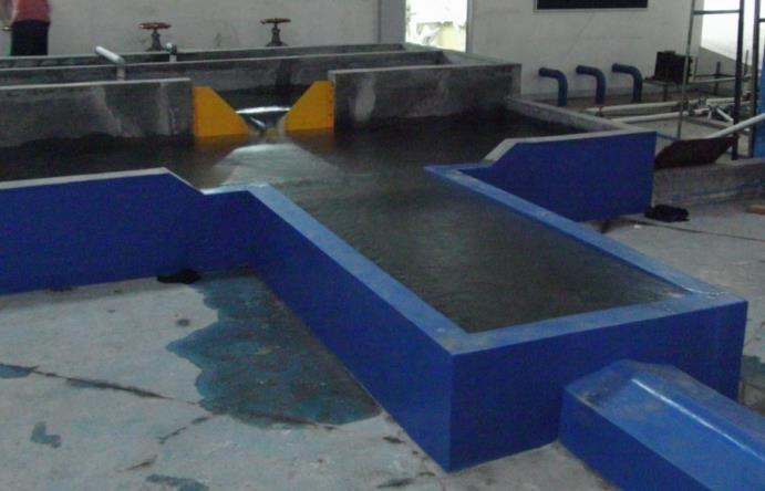
3 General layout inner dia. 3.2 m length ±60 m 3
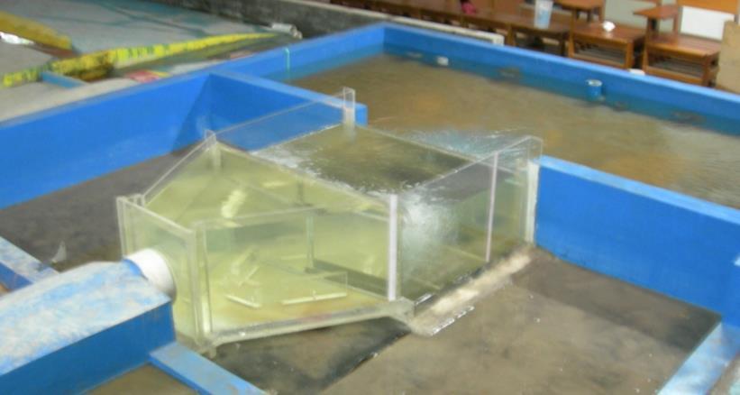
4 Model scale is defined at 1:15 considering Availability of space Pump capacity Measuring instruments A non-distorted model, i.e. similar horizontal and vertical length scale, is selected 4

5 Parameters Model Scale Notation Calculation Magnitude Length, Width n L n L 15 Depth n L n L 15 Area n A n 2 L 225 Volume n V n 3 L 3,375 Time n T n 1/2 L 3.87 Velocity n U n 1/2 L 3.87 Discharge n Q n 5/2 L


6 Model scale 1:15 made of acrylic material 6
7 7
8 8
 HWL 5.4 m 36 cm LWL 4.")
9 Model scale 1:15 Parameters Prototype Model Magnitude Unit Magnitude Unit Discharge structure length 24 m 160 cm width 16 m cm depth 7.9 m 52.7 cm Discharge 2-pump operation 65,200 m 3 /h 20.8 l/s 1-pump operation 39,120 m 3 /h 12.5 l/s Downstream flow depth (at the Outfall) HWL 5.4 m 36 cm LWL 4.4 m 29.3 cm 9
10 Water Surface Profile Energy Dissipation 10

11 Water surface profile computation Standard step method One dimensional calculation Use of HEC-RAS model Energy dissipation computation Analytical calculation Calculation procedure follows the method explained in the USBS Design of Small Dams 11
12 Computational Domain Head tank (pump pit) Discharge line Seal Pit CW D i s c ha r ge Channel Examples of cross sections Seal Pit Java Sea HEC RAS Tanjung Priok Plan: CW discharge 1 and 2 pump operation HEC RAS Tanjung Priok Plan: CW discharge 1 and 2 pump operation 3 Legend 3 Legend 2 Ground Bank Sta 2 Ground Bank Sta 1 1 Elevation (m) 0-1 Elevation (m) of Geo-Ref the Non XS's user Non interpolated are entered Geo-Referenced usxs interpolated XS entered XS ( XS) Station (m) Station (m) None of Geo-Ref the Non XS's user Non interpolated are entered Geo-Referenced usxs interpolated XS entered XS ( XS) Stilling Basin 12
13 Values of parameters applied in the water surface profile computation Parameter Discharge Sea water level Magnitude 39,120 m 3 /h (one-pump operation) 65,200 m 3 /h (two-pump operation) 0.56 m (LWL) m (HWL) Manning roughness coefficient Discharge coefficient of the sill
14 One-pump operation, Q = 39,120 m 3 /s HEC RAS Tanjung Priok Plan: CW discharge 1 and 2 pump operation CW Discharge Channel Legend WS Q HWL Elevation (m) HWL +0.42m LWL 0.56m Java Sea Training wall +2.90m WS +0.62m Stilling Basin WS +2.31m Seal Pit Pipe WS Q LWL Ground ROB Main Channel Distance (m) 14
15 Two-pump operation, Q = 65,200 m 3 /s HEC RAS Tanjung Priok Plan: CW discharge 1 and 2 pump operation CW Discharge Channel Legend WS Q HWL Elevation (m) HWL +0.42m LWL 0.56m Java Sea Training wall +2.90m WS +0.86m Stilling Basin WS +2.56m Seal Pit Pipe WS Q LWL Ground ROB Main Channel Distance (m) 15
16 Conclusion Distance of the maximum water surface at the Seal Pit from the training wall crest is only 30 cm but at the Stilling Basin is 2 m Free-board at the Seal Pit is thus not sufficient but at the Stilling Basin is too high 16
17 Recommendation Increase of training wall along the Seal Pit from m to m Lower down the training wall crest at the Stilling Basin from m to 1.90 m 17
18 H e h d h d H e Y P d TW 2.15d c P 0.8d c L p 0.8d c L B L P d c 18
19 Parameter Symbol Cooling water discharge 39,120 m 3 /h 65,200 m 3 /h Width of sill crest b 16 m 16 m Unit discharge q m 3 /s/m m 3 /s/m Critical depth d c 0.36 m 0.51 m Upstream head H e 0.62 m 0.87 m Drop height h d 1.70 m 1.70 m Seal Pit water surface elevation m m Stilling Basin water surface elevation m m Stilling Basin water depth d TW 5.62 m 5.87 m Distance of impinging jet from the sill L p 3.35 m 4.69 m Minimum distance of impact block from the L p + 0.8d c 3.64 m 5.09 m sill Minimum length of Stilling Basin L B L p d c 4.27 m 5.78 m Minimum water depth in the Stilling Basin d TW 2.15 d c 0.78 m 1.09 m 19
20 Conclusion The energy dissipation (by free overfall and Stilling Basin) satisfies the requirement Recommendation Displacement of the impact block farther away from the overflow present position at 3.25 m to 5.10 m This is not critical since the basin depth is much deeper than the requirement 20
21 Water Surface Profile Energy Dissipation Flow Velocity Flow Pattern 21
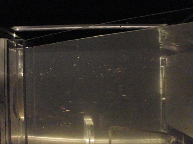
22 Two measurements are done Water surface profile Electronic device Flow velocity Imaging technique (PIV) Acoustic Doppler (ADV) Additional instuments Distance, level Staff gauge Meter tape Discharge V-notch 22


23 Acoustic Doppler Velocimeter to measure flow velocity Imaging technique to measure flow pattern Capacitance level meter to measure water level (dynamic) 23


24 Staff gauge, meter tape to measure distance, depth, elevation 24
25 Water surface profile Energy dissipation Flow pattern Flow velocity 25


26 Software EXEL Data of Water Level At Q h=14.6cm H=421mm H=375mm H=334.5mm 26
 Light")

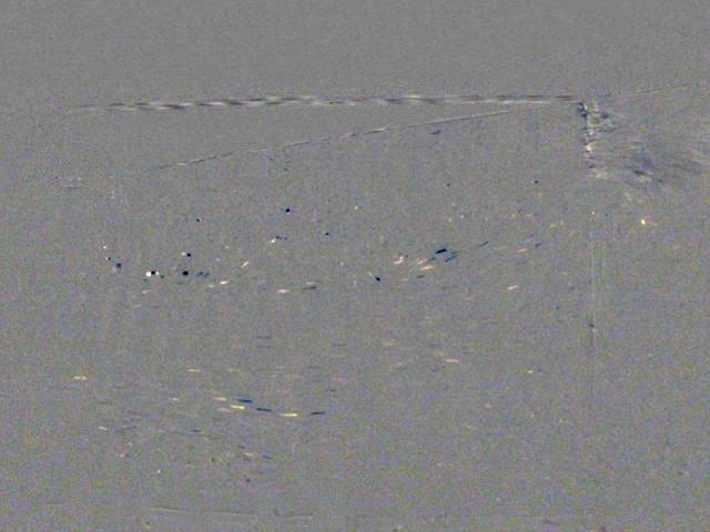
27 Flow Pattern (PIV) Light Sheet Source Model Camera 27
28 28
29 Instantaneous velocity (time average) velocity turbulence intensity and stress 29
30 30
31 31
32 32
33 33
Beaver Creek Corridor Design and Analysis. By: Alex Previte
 Beaver Creek Corridor Design and Analysis By: Alex Previte Overview Introduction Key concepts Model Development Design Accuracy Conclusion Refresh v = Beaver Creek Site = Wittenberg Introduction Low head
Study on river-discharge measurements with a bottom-mounted ADCP
 Study on river-discharge measurements with a bottom-mounted ADCP Y. Nihei & T. Sakai Tokyo University of Science, Dept. of Civil Engineering, Chiba, Japan ABSTRACT: To examine the accuracy of discharge
Stage Discharge Tabulation for Only Orifice Flow
 Stage Discharge Tabulation for Only Orifice Flow DEPTH STAGE DISCHARGE (meters) (feet) (meters) (feet) (m 3 /s) (ft 3 /s) 0 0.20 0.40 0.60 0.80 1.00 1.20 1.40 1.60 1.80 2.00 0.7 1.3 2.0 2.6 3.3 3.9 4.6
Rock Sizing for Multi-Pipe & Culvert Outlets
 Rock Sizing for Multi-Pipe & Culvert Outlets STORMWATER AND WATERWAY MANAGEMENT PRACTICES Photo 1 Rock pad outlet structure at end of a duel stormwater pipe outlet Photo 2 Rock pad outlet structure at
Cavitation occurs whenever the pressure in the flow of water drops to the value of the pressure of the saturated water vapour, pv (at the prevailing
 Cavitation occurs whenever the pressure in the flow of water drops to the value of the pressure of the saturated water vapour, pv (at the prevailing temperature); cavities filled by vapour, and partly
Calibration of Manning s Friction Factor for Rivers in Iraq Using Hydraulic Model (Al-Kufa River as Case study)
") Calibration of Manning s Friction Factor for Rivers in Iraq Using Hydraulic Model (Al-Kufa River as Case study) Luay Kadhim Hameed, Civil Engineering Dept./ University of Kufa Hayder Sami Mohammed, Structure
Calibration of Manning s Friction Factor for Rivers in Iraq Using Hydraulic Model (Al-Kufa River as Case study) Luay Kadhim Hameed, Civil Engineering Dept./ University of Kufa Hayder Sami Mohammed, Structure
FLOOD HAZARD AND RISK ASSESSMENT IN MID- EASTERN PART OF DHAKA, BANGLADESH
 FLOOD HAZARD AND RISK ASSESSMENT IN MID- EASTERN PART OF DHAKA, BANGLADESH Muhammad MASOOD MEE07180 Supervisor: Prof. Kuniyoshi TAKEUCHI ABSTRACT An inundation simulation has been done for the mid-eastern
DEPARTMENT OF CIVIL AND ENVIRONMENTAL ENGINEERING Urban Drainage: Hydraulics. Solutions to problem sheet 2: Flows in open channels
 DEPRTMENT OF CIVIL ND ENVIRONMENTL ENGINEERING Urban Drainage: Hydraulics Solutions to problem sheet 2: Flows in open channels 1. rectangular channel of 1 m width carries water at a rate 0.1 m 3 /s. Plot
Numerical Simulations And Laboratory Measurements In Hydraulic Jumps
 City University of New York (CUNY) CUNY Academic Works International Conference on Hydroinformatics 8-1-2014 Numerical Simulations And Laboratory Measurements In Hydraulic Jumps Luis G. Castillo José M.
y 2 = 1 + y 1 This is known as the broad-crested weir which is characterized by:
 CEE 10 Open Channel Flow, Dec. 1, 010 18 8.16 Review Flow through a contraction Critical and choked flows The hydraulic jump conservation of linear momentum y = 1 + y 1 1 + 8Fr 1 8.17 Rapidly Varied Flows
Hydraulics of bendway weirs
 River Basin Management IV 389 Hydraulics of bendway weirs C. Thornton 1, S. Abt 1, D. Baird 2 & R. Padilla 3 1 Colorado State University, Fort Collins, CO, USA 2 U.S. Bureau of Reclamation, Denver, CO,
DEC Departamento de Engenharia Civil
 LABORATÓRIO DE HIDRÁULICA DA FEUP. UM FUTURO COM ESTRATÉGIA. FEUP outubro 2013 Fernando Veloso Gomes outubro 2013 LABORATÓRIO DE HIDRÁULICA DA FEUP. UM FUTURO COM ESTRATÉGIA DEC Departamento de Engenharia
1.060 Engineering Mechanics II Spring Problem Set 8
 1.060 Engineering Mechanics II Spring 2006 Due on Monday, May 1st Problem Set 8 Important note: Please start a new sheet of paper for each problem in the problem set. Write the names of the group members
FE Fluids Review March 23, 2012 Steve Burian (Civil & Environmental Engineering)
") Topic: Fluid Properties 1. If 6 m 3 of oil weighs 47 kn, calculate its specific weight, density, and specific gravity. 2. 10.0 L of an incompressible liquid exert a force of 20 N at the earth s surface.
Topic: Fluid Properties 1. If 6 m 3 of oil weighs 47 kn, calculate its specific weight, density, and specific gravity. 2. 10.0 L of an incompressible liquid exert a force of 20 N at the earth s surface.
conservation of linear momentum 1+8Fr = 1+ Sufficiently short that energy loss due to channel friction is negligible h L = 0 Bernoulli s equation.
 174 Review Flow through a contraction Critical and choked flows The hydraulic jump conservation of linear momentum y y 1 = 1+ 1+8Fr 1 8.1 Rapidly Varied Flows Weirs 8.1.1 Broad-Crested Weir Consider the
COMPARISON OF LABORATORY AND FIELD MEASUREMENTS OF BRIDGE PIER SCOUR
 COMPARISON OF LABORATORY AND FIELD MEASUREMENTS OF BRIDGE PIER SCOUR LEE, SEUNGOH, STURM, T. W., School of Civil and Environ. Engrg., Georgia Institute of Technology Atlanta, GA 30332-0512 USA GOTVALD,
CONCEPTS Conservational Channel Evolution and Pollutant Transport System
 CONCEPTS Conservational Channel Evolution and Pollutant Transport System Eddy J. Langendoen Watershed Physical Processes Research Unit National Sedimentation Laboratory USDA Agricultural Research Service
Formation Of Hydraulic Jumps On Corrugated Beds
 International Journal of Civil & Environmental Engineering IJCEE-IJENS Vol:10 No:01 37 Formation Of Hydraulic Jumps On Corrugated Beds Ibrahim H. Elsebaie 1 and Shazy Shabayek Abstract A study of the effect
Vegetation effects on river hydraulics. Johannes J. (Joe) DeVries David Ford Consulting Engineers, Inc. Sacramento, CA
 DeVries David Ford Consulting Engineers, Inc. Sacramento, CA") Vegetation effects on river hydraulics Johannes J. (Joe) DeVries David Ford Consulting Engineers, Inc. Sacramento, CA jjdevries@ford-consulting.com SAC05 D2P31 RM 99.0L VIEW UPSTREAM AT UPSTREAM END DWR
Vegetation effects on river hydraulics Johannes J. (Joe) DeVries David Ford Consulting Engineers, Inc. Sacramento, CA jjdevries@ford-consulting.com SAC05 D2P31 RM 99.0L VIEW UPSTREAM AT UPSTREAM END DWR
FORMATION OF HYDRAULIC JUMPS ON CORRUGATED BEDS
 International Journal of Civil & Environmental Engineering IJCEE-IJENS Vol: 10 No: 01 40 FORMATION OF HYDRAULIC JUMPS ON CORRUGATED BEDS Ibrahim H. Elsebaie 1 and Shazy Shabayek Abstract A study of the
Dam Break Analysis Using HEC-RAS and HEC-GeoRAS A Case Study of Ajwa Reservoir
 Journal of Water Resources and Ocean Science 2016; 5(6): 108-113 http://www.sciencepublishinggroup.com/j/wros doi: 10.11648/j.wros.20160506.15 ISSN: 2328-7969 (Print); ISSN: 2328-7993 (Online) Case Report
CVE 372 HYDROMECHANICS EXERCISE PROBLEMS
 VE 37 HYDROMEHNIS EXERISE PROLEMS 1. pump that has the characteristic curve shown in the accompanying graph is to be installed in the system shown. What will be the discharge of water in the system? Take
Chapter 3.8: Energy Dissipators. By Dr. Nuray Denli Tokyay
 Chapter 3.8: Energy Dissipators By Dr. Nuray Denli Tokyay 3.1 Introduction A stilling basin is a short length of paved channel placed at the foot of a spillway or any other source of supercritical flow
Rock Sizing for Waterway & Gully Chutes
 Rock Sizing for Waterway & Gully Chutes WATERWAY MANAGEMENT PRACTICES Photo 1 Rock-lined waterway chute Photo 2 Rock-lined gully chute 1. Introduction A waterway chute is a stabilised section of channel
HEC-RAS Reservoir Transport Simulation of Three Reservoirs in the Lower Susquehanna River Basin. Mike Langland and Ed Koerkle
 HEC-RAS Reservoir Transport Simulation of Three Reservoirs in the Lower Susquehanna River Basin Mike Langland and Ed Koerkle Topics Background / Project Objectives Data Selection - Sediment and Geometric
River Ice Modelling. Hydraulic Modelling of Mackenzie River at Ft. Province, NWT, Canada
 River Ice Modelling Hydraulic Modelling of Mackenzie River at Ft. Province, NWT, Canada Submitted to F.E. Hicks, PhD, PEng, FCSCE Professor, Dept. of Civil and Environmental Engineering University of Alberta
1.060 Engineering Mechanics II Spring Problem Set 4
 1.060 Engineering Mechanics II Spring 2006 Due on Monday, March 20th Problem Set 4 Important note: Please start a new sheet of paper for each problem in the problem set. Write the names of the group members
53:071 Principles of Hydraulics Laboratory Experiment #3 ANALYSIS OF OPEN-CHANNEL FLOW TRANSITIONS USING THE SPECIFIC ENERGY DIAGRAM
 53:071 Principles of Hydraulics Laboratory Experiment #3 ANALYSIS OF OPEN-CHANNEL FLOW TRANSITIONS USING THE SPECIFIC ENERGY DIAGRAM Principle Adaptation of the Bernoulli equation to open-channel flows
UPPER COSUMNES RIVER FLOOD MAPPING
 UPPER COSUMNES RIVER FLOOD MAPPING DRAFT BASIC DATA NARRATIVE FLOOD INSURANCE STUDY SACRAMENTO COUTY, CALIFORNIA Community No. 060262 November 2008 Prepared By: CIVIL ENGINEERING SOLUTIONS, INC. 1325 Howe
Laboratory Investigation of Submerged Vane Shapes Effect on River Banks Protection
 Australian Journal of Basic and Applied Sciences, 5(12): 1402-1407, 2011 ISSN 1991-8178 Laboratory Investigation of Submerged Vane Shapes Effect on River Banks Protection Touraj Samimi Behbahan Department
Coarse Sediment Traps
 Coarse Sediment Traps SEDIMENT CONTROL TECHNIQUE Type 1 System Sheet Flow Sandy Soils Type 2 System [1] Concentrated Flow Clayey Soils [2] Type 3 System Supplementary Trap Dispersive Soils [1] Though primarily
A TIPPING-BUCKET SEDIMENT TRAP FOR CONTINUOUS MONITORING OF SEDIMENT DEPOSITION RATE
 A TIPPING-BUCKET SEDIMENT TRAP FOR CONTINUOUS MONITORING OF SEDIMENT DEPOSITION RATE YASUO NIHEI AND YUICHI IMASHIMIZU Department of Civil Eng., Tokyo University of Science, 2641 Yamazaki, Noda-shi 278-851,
Discharge measurements
 Discharge measurements DISCHARGE MEASUREMENTS Suitability of methods and equipment for measurements where, under what conditions and for what reason discharge is measured determination of discharge in
Head Discharge Relationship of Thin Plated Rectangular Lab Fabricated Sharp Crested Weirs
 Journal of Applied Fluid Mechanics, Vol. 9, No. 3, pp. 1231-1235, 2016. Available online at www.jafmonline.net, ISSN 1735-3572, EISSN 1735-3645. DOI: 10.18869/acadpub.jafm.68.228.23128 Head Discharge Relationship
How to Design Bendway Weirs
 How to Design Bendway Weirs Project Background U.S. Bureau of Reclamation: Middle Rio Grande Channel Maintenance Program 29-Mile Study Reach: Cochiti Dam to Bernalillo Geomorphic Changes Due to Dam Construction
MODELING OF LOCAL SCOUR AROUND AL-KUFA BRIDGE PIERS Saleh I. Khassaf, Saja Sadeq Shakir
 ISSN 2320-9100 11 International Journal of Advance Research, IJOAR.org Volume 1, Issue 8,August 2013, Online: ISSN 2320-9100 MODELING OF LOCAL SCOUR AROUND AL-KUFA BRIDGE PIERS Saleh I. Khassaf, Saja Sadeq
 http://water.usgs.gov/waterwatch/ Stream Flow Measurement: Velocity-Area method Stream discharge = Q = U * A Q = volumetric flow rate in [L 3 T -1 ] U= average stream velocity [L 2 T -1 ] A = cross sectional
UNIT I FLUID PROPERTIES AND STATICS
 SIDDHARTH GROUP OF INSTITUTIONS :: PUTTUR Siddharth Nagar, Narayanavanam Road 517583 QUESTION BANK (DESCRIPTIVE) Subject with Code : Fluid Mechanics (16CE106) Year & Sem: II-B.Tech & I-Sem Course & Branch:
Modeling of long-term sedimentation in the Osijek port basin
 Water Management and Hydraulic Engineering 2015 Litera Brno, ISBN 978-80-214-5230-5, ISSN 2410-5910 Modeling of long-term sedimentation in the Osijek port basin G. Gilja, N. Kuspilić (Faculty of civil
Rock Sizing for Small Dam Spillways
 Rock Sizing for Small Dam Spillways STORMWATER MANAGEMENT PRACTICES Photo 1 Rock-lined spillway on a construction site sediment basin Photo 2 Rock-lined spillway on a small farm dam 1. Introduction A chute
Climate Adaptation Challenges for Boston s Water and Sewer Systems
 National Association of Flood & Stormwater Management Agencies Climate Adaptation Challenges for Boston s Water and Sewer Systems John P Sullivan P.E. October 15,2014 Boston 1630 Boston 1630-2012 Boston
NPTEL Quiz Hydraulics
 Introduction NPTEL Quiz Hydraulics 1. An ideal fluid is a. One which obeys Newton s law of viscosity b. Frictionless and incompressible c. Very viscous d. Frictionless and compressible 2. The unit of kinematic
Experiments on the perturbation of a channel flow by a triangular ripple
 Experiments on the perturbation of a channel flow by a triangular ripple F. Cúñez *, E. Franklin Faculty of Mechanical Engineering, University of Campinas, Brazil * Correspondent author: fernandodcb@fem.unicamp.br
Turbulence Laboratory
 Objective: CE 319F Elementary Mechanics of Fluids Department of Civil, Architectural and Environmental Engineering The University of Texas at Austin Turbulence Laboratory The objective of this laboratory
R09. d water surface. Prove that the depth of pressure is equal to p +.
 Code No:A109210105 R09 SET-1 B.Tech II Year - I Semester Examinations, December 2011 FLUID MECHANICS (CIVIL ENGINEERING) Time: 3 hours Max. Marks: 75 Answer any five questions All questions carry equal
If a stream of uniform velocity flows into a blunt body, the stream lines take a pattern similar to this: Streamlines around a blunt body
 Venturimeter & Orificemeter ELEMENTARY HYDRAULICS National Certificate in Technology (Civil Engineering) Chapter 5 Applications of the Bernoulli Equation The Bernoulli equation can be applied to a great
UNIT IV. Flow through Orifice and Mouthpieces and Flow through Notchs and Weirs
 SIDDHARTH GROUP OF INSTITUTIONS :: PUTTUR Siddharth Nagar, Narayanavanam Road 517583 QUESTION BANK (DESCRIPTIVE) Subject with Code : FM(15A01305) Year & Sem: II-B.Tech & I-Sem Course & Branch: B.Tech -
PENNSYLVANIA DEPARTMENT OF TRANSPORTATION ENGINEERING DISTRICT 3-0
 PENNSYLVANIA DEPARTMENT OF TRANSPORTATION ENGINEERING DISTRICT 3-0 LYCOMING COUNTY S.R.15, SECTION C41 FINAL HYDROLOGIC AND HYDRAULIC REPORT STEAM VALLEY RUN STREAM RELOCATION DATE: June, 2006 REVISED:
Storm Water Best Management Practice: Development of Debris Filtering Structure for Supercritical Flow
 Storm Water Best Management Practice: Development of Debris Filtering Structure for Supercritical Flow Jungseok Ho 1, Todd Marti 2, and Julie Coonrod 3 1 Department of Civil Engineering, University of
INFLOW DESIGN FLOOD CONTROL SYSTEM PLAN 40 C.F.R. PART PLANT YATES ASH POND 2 (AP-2) GEORGIA POWER COMPANY
 GEORGIA POWER COMPANY") INFLOW DESIGN FLOOD CONTROL SYSTEM PLAN 40 C.F.R. PART 257.82 PLANT YATES ASH POND 2 (AP-2) GEORGIA POWER COMPANY EPA s Disposal of Coal Combustion Residuals from Electric Utilities Final Rule (40 C.F.R.
INFLOW DESIGN FLOOD CONTROL SYSTEM PLAN 40 C.F.R. PART 257.82 PLANT YATES ASH POND 2 (AP-2) GEORGIA POWER COMPANY EPA s Disposal of Coal Combustion Residuals from Electric Utilities Final Rule (40 C.F.R.
Accounting for increased flow resistance due to lateral momentum loss in restoration designs using 2-stage channels
 Skamania 2005 Accounting for increased flow resistance due to lateral momentum loss in restoration designs using 2-stage channels Outline Aim and Objectives Definition Use of 2-stage channels in stream
Open Channel Hydraulics III - Sharpcrested
 PDHonline Course H140 (2 PDH) Open Channel Hydraulics III - Sharpcrested Weirs Instructor: Harlan H. Bengtson, Ph.D., PE 2012 PDH Online PDH Center 5272 Meadow Estates Drive Fairfax, VA 22030-6658 Phone
Flow Field Investigation in a Rectangular Shallow Reservoir using UVP, LSPIV and numerical model
 Flow Field Investigation in a Rectangular Shallow Reservoir using UVP, LSPIV and numerical model S AMEH KANTOUSH, ERIK BOLLAERT, GIOVANNI DE CESARE, JEAN-LOUIS BOILLAT and ANTON SCHLEISS Ecole Polytechnique
Experimental Study of Discharge Characteristics in a Compound Meandering River
 American Journal of Engineering Research (AJER) e-issn : 2320-0847 p-issn : 2320-0936 Volume-02, Issue-07, pp-136-140 www.ajer.org Research Paper Open Access Experimental Study of Discharge Characteristics
Figure 1. Schematic of experimental setup.
 June 3 - July 3, Melbourne, Australia 9 9D- STRUCTURE OF 3D OFFSET JETS OVER A SURFACE MOUNTED SQUARE RIB Shawn P. Clark Department of Civil Engineering 7A Chancellors Circle, Winnipeg, Manitoba, R3T V,
Evaluation of Scour Depth around Bridge Piers with Various Geometrical Shapes
 Evaluation of Scour Depth around Bridge Piers with Various Geometrical Shapes Dr. P. D. Dahe * Department of Civil Engineering, SGGSIE&T, Vishnupuri, Nanded (Maharashtra) S. B. Kharode Department of Civil
Field Observations and One-Dimensional Flow Modeling of Summit Creek in Mack Park, Smithfield, Utah
 Intermountain Center for River Rehabilitation and Restoration, Utah State University 31 July 2018 Field Observations and One-Dimensional Flow Modeling of Summit Creek in Mack Park, Smithfield, Utah I.
Determination of Crest Coefficient for Flow over Trapezoidal Labyrinth Weir
 World Applied Sciences Journal 1 (): 4-9, 011 ISSN 1818-495 IDOSI Publications, 011 Determination of Crest Coefficient for Flow over Trapezoidal abyrinth Weir 1 4 B.V. Khode, A.R. Tembhurkar, P.D. Porey
Applied Fluid Mechanics
 Applied Fluid Mechanics 1. The Nature of Fluid and the Study of Fluid Mechanics 2. Viscosity of Fluid 3. Pressure Measurement 4. Forces Due to Static Fluid 5. Buoyancy and Stability 6. Flow of Fluid and
Advt.No.Rect/Admn-II/2017/7 - Job.No.232 Technical Superintendent
 Advt.No.Rect/Admn-II/2017/7 - Job.No.232 Technical Superintendent Sample Question Paper & Syllabus for Skill Test 50 Marks 2 Hours Note: Sample questions given are only indicative in nature and not exhaustive.
5 ENERGY EQUATION OF FLUID MOTION
 5 ENERGY EQUATION OF FLUID MOTION 5.1 Introduction In order to develop the equations that describe a flow, it is assumed that fluids are subject to certain fundamental laws of physics. The pertinent laws
Opanuku Stream Benchmark Validation 1. Introduction. 2. The Opanuku Stream Model
 Opanuku Stream Benchmark Validation 1. Introduction The model accuracy benchmark published by the Flood Risk Management Committee of the IAHR in http://members.iahr.org/imis/communitymanagement/communitylayouts/flood_risk_manageme
EFFECT OF BAFFLE BLOCKS ON THE PERFORMANCE OF RADIAL HYDRAULIC JUMP
 Fourth International Water Technology Conference IWTC 99, Alexandria, Egypt 255 EFFECT OF BAFFLE BLOCKS ON THE PERFORMANCE OF RADIAL HYDRAULIC JUMP O. S. Rageh Irrigation & Hydraulics Dept., Faculty of
Hydraulics and hydrology
 Hydraulics and hydrology - project exercises - Class 4 and 5 Pipe flow Discharge (Q) (called also as the volume flow rate) is the volume of fluid that passes through an area per unit time. The discharge
Experiment (4): Flow measurement
: Flow measurement") Experiment (4): Flow measurement Introduction: The flow measuring apparatus is used to familiarize the students with typical methods of flow measurement of an incompressible fluid and, at the same time
Experiment (4): Flow measurement Introduction: The flow measuring apparatus is used to familiarize the students with typical methods of flow measurement of an incompressible fluid and, at the same time
Review of pipe flow: Friction & Minor Losses
 ENVE 204 Lecture -1 Review of pipe flow: Friction & Minor Losses Assist. Prof. Neslihan SEMERCİ Marmara University Department of Environmental Engineering Important Definitions Pressure Pipe Flow: Refers
Stormwater Outlet Sediment Traps
 Stormwater Outlet Traps SEDIMENT CONTROL TECHNIQUES Photo 1 Excavated sediment trap just prior to scheduled clean-out (note energy dissipater at end of pipe) Photo 2 A supplementary straw bale barrier
Investigation of Flow Profile in Open Channels using CFD
 Investigation of Flow Profile in Open Channels using CFD B. K. Gandhi 1, H.K. Verma 2 and Boby Abraham 3 Abstract Accuracy of the efficiency measurement of a hydro-electric generating unit depends on the
CIE4491 Lecture. Hydraulic design
 CIE4491 Lecture. Hydraulic design Marie-claire ten Veldhuis 19-9-013 Delft University of Technology Challenge the future Hydraulic design of urban stormwater systems Focus on sewer pipes Pressurized and
Experimental Investigation on Density Currents Propagating over Smooth and Rough Beds
 Experimental Investigation on Density Currents Propagating over Smooth and Rough Beds Reza Nasrollahpour 1, Mohamad Hidayat Bin Jamal 2*, Mehdi Ghomeshi 3, Peiman Roushenas 4 1,2,4 Faculty of Civil Engineering,
Descriptions of Flow
 Civil Engineering Hydraulics Up until this point, we have only considered fluids that were not in motion therefore we were limited to fluids that did not have any velocity. This limited our analytical
An experimental study of longitudinal velocity distribution at cross-over and bend section of a compound meandering channel
 American Journal of Civil Engineering 2013; 1(3): 124-128 Published online November 20, 2013 (http://www.sciencepublishinggroup.com/j/ajce) doi: 10.11648/j.ajce.20130103.16 An experimental study of longitudinal
For example an empty bucket weighs 2.0kg. After 7 seconds of collecting water the bucket weighs 8.0kg, then:
 Hydraulic Coefficient & Flow Measurements ELEMENTARY HYDRAULICS National Certificate in Technology (Civil Engineering) Chapter 3 1. Mass flow rate If we want to measure the rate at which water is flowing
Chapter 5 CALIBRATION AND VERIFICATION
 Chapter 5 CALIBRATION AND VERIFICATION This chapter contains the calibration procedure and data used for the LSC existing conditions model. The goal of the calibration effort was to develop a hydraulic
DETERMINATION OF DISCHARGE COEFFICIENT FOR FLOW OVER ONE CYCLE COMPOUND TRAPEZOIDAL PLAN FORM LABYRINTH WEIR
 International Journal of Civil Engineering and Technology (IJCIET) Volume 7, Issue 4, July-August 2016, pp. 314 328 Article ID: IJCIET_07_04_027 Available online at http://www.iaeme.com/ijciet/issues.asp?jtype=ijciet&vtype=7&itype=4
SCALING ISSUES FOR LABORATORY MODELING OF BRIDGE PIER SCOUR
 A-2 Fourth International Conference on Scour and Erosion 2008 SCALING ISSUES FOR LABORATORY MODELING OF BRIDGE PIER SCOUR Seung Oh LEE 1 and Terry STURM 2 1 Instructor, School of Urban and Civil Engineering,
HYDRAULIC MODELLING OF NENJIANG RIVER FLOODPLAIN IN NORTHEAST CHINA
 HYDRAULIC MODELLING OF NENJIANG RIVER FLOODPLAIN IN NORTHEAST CHINA Xiao Fei MEE08181 Supervisor: A.W. Jayawardena ABSTRACT In 1998, the worst flood recorded for over 200 years hit the Songhua River Basin
Sediment Extraction and Flow Structure of Vortex Settling Basin
 Sediment Extraction and Flow Structure of Vortex Settling Basin J. Chapokpour 1, J. Farhoudi 2 1- Post Graduate Student, Hyd. Structures, Dept. of Irrigation Eng., Faculty of agricultural technology and
Kinetic energy and momentum correction factors in a stream
 Kinetic energy and momentum correction factors in a stream Mehmet Ardıçlıoğlu, Mücella Vapur, 2Onur Genç, University of Erciyes, Department of Civil Engineering, Kayseri, Turkey 2 Melikşah University,
A TRANSITION FLOW REGIME ON STEPPED SPILLWAYS THE
 A TRANSITION FLOW REGIME ON STEPPED SPILLWAYS THE FACTS H. Chanson Department of Civil Engineering, The University of Queensland, Brisbane QLD 4072, Australia Fax: (61 7) 33 65 45 99 - E-mail: h.chanson@mailbox.uq.edu.au
DEPARTMENT OF CHEMICAL ENGINEERING University of Engineering & Technology, Lahore. Fluid Mechanics Lab
 DEPARTMENT OF CHEMICAL ENGINEERING University of Engineering & Technology, Lahore Fluid Mechanics Lab Introduction Fluid Mechanics laboratory provides a hands on environment that is crucial for developing
Flood Capacity of Shirakawa River at Tatsudajinnnai Area in Kumamoto Prefecture
 International Journal of Economy, Energy and Environment 218; 3(5): 51-57 http://www.sciencepublishinggroup.com/j/ijeee doi: 1.11648/j.ijeee.21835.13 ISSN: 2575-513 (Print); ISSN: 2575-521 (Online) Flood
SPILLWAY CHUTES DESCARREGADORES DE CHEIA COM QUEDA GUIADA
 SPILLWAY CHUTES DESCARREGADORES DE CHEIA COM QUEDA GUIADA Hydropower Hidroenergia Jorge Matos 1 and Inês Lúcio 2 1 jorge.matos@tecnico.ulisboa.pt 2 ines.lucio@tecnico.ulisboa.pt 1 Spillway chutes Descarregadores
Chutes Part 5: Rock linings
 Chutes Part 5: Rock linings DRAINAGE CONTROL TECHNIQUE Low Gradient Velocity Control Short-Term Steep Gradient Channel Lining Medium-Long Term Outlet Control [1] Soil Treatment Permanent [2] [1] Chutes
P10.5 Water flows down a rectangular channel that is 4 ft wide and 3 ft deep. The flow rate is 15,000 gal/min. Estimate the Froude number of the flow.
 P10.5 Water flows down a rectangular channel that is 4 ft wide and ft deep. The flow rate is 15,000 gal/min. Estimate the Froude number of the flow. Solution: Convert the flow rate from 15,000 gal/min
LECTURE 6- ENERGY LOSSES IN HYDRAULIC SYSTEMS SELF EVALUATION QUESTIONS AND ANSWERS
 LECTURE 6- ENERGY LOSSES IN HYDRAULIC SYSTEMS SELF EVALUATION QUESTIONS AND ANSWERS 1. What is the head loss ( in units of bars) across a 30mm wide open gate valve when oil ( SG=0.9) flow through at a
Measurements of Turbulent Pressure Under Breaking Waves
 MEASUREMENTS OF TURBULENT PRESSURE UNDER BREAKING WAVES 33 Measurements of Turbulent Pressure Under Breaking Waves Author: Faculty Sponsor: Department: Christopher Olsen Francis Ting, Ph.D., P.E. Civil
YELLOWSTONE RIVER FLOOD STUDY REPORT TEXT
 YELLOWSTONE RIVER FLOOD STUDY REPORT TEXT TECHNICAL REPORT Prepared for: City of Livingston 411 East Callender Livingston, MT 59047 Prepared by: Clear Creek Hydrology, Inc. 1627 West Main Street, #294
Rapid Operation of a Tainter Gate: the Transient Flow Motion
 5 th International Symposium on Hydraulic Structures Brisbane, Australia, 25-27 June 2014 Hydraulic Structures and Society: Engineering Challenges and Extremes ISBN 9781742721156 - DOI: 10.14264/uql.2014.27
New computation method for flood flows and bed variations in a low-lying river with complex river systems
 River Flow 2014 Schleiss et al. (Eds) 2014 Taylor & Francis Group, London, ISBN 978-1-138-02674-2 New computation method for flood flows and bed variations in a low-lying river with complex river systems
Experimental and Numerical Investigation of Two- Phase Flow through Enlarging Singularity
 Purdue University Purdue e-pubs International Refrigeration and Air Conditioning Conference School of Mechanical Engineering 212 Experimental and Numerical Investigation of Two- Phase Flow through Enlarging
V-NOTCH _ V-NOTCH FLOW METERS HYDROLOGICAL INSTRUMENTS
 _ V-NOTCH FLOW METERS HYDROLOGICAL INSTRUMENTS V-NOTCH FLOW METERS Water flow monitoring in open channels is widely employed in environmental and geotechnical field. Leakage measurement is one of the most
A STUDY OF LOCAL SCOUR AT BRIDGE PIERS OF EL-MINIA
 A STUDY OF LOCAL SCOUR AT BRIDGE PIERS OF EL-MINIA Dr. Gamal A. Sallam 1 and Dr. Medhat Aziz 2 ABSTRACT Bridges are critical structures that require a substantial investment to construct and serve an important
 CE 6303 MECHANICS OF FLUIDS L T P C QUESTION BANK 3 0 0 3 UNIT I FLUID PROPERTIES AND FLUID STATICS PART - A 1. Define fluid and fluid mechanics. 2. Define real and ideal fluids. 3. Define mass density
Extreme Phenomena in Dobrogea - Floods and Droughts
 Extreme Phenomena in Dobrogea - Floods and Droughts PhD eng. Carmen Maftei Ovidius University of Constanta (Partner no 4) OUTLINES Introduction Study area Drought Floods Conclusion What is the problem?
Free Flow Below Skew Sluice Gate
 International Journal of Engineering Research and Development e-issn: 2278-67X, p-issn: 2278-8X, www.ijerd.com Volume, Issue 3 (March 24), PP.44-52 Talib Mansoor Civil Engineering Department, Aligarh Muslim
Piping Systems and Flow Analysis (Chapter 3)
") Piping Systems and Flow Analysis (Chapter 3) 2 Learning Outcomes (Chapter 3) Losses in Piping Systems Major losses Minor losses Pipe Networks Pipes in series Pipes in parallel Manifolds and Distribution
Piping Systems and Flow Analysis (Chapter 3) 2 Learning Outcomes (Chapter 3) Losses in Piping Systems Major losses Minor losses Pipe Networks Pipes in series Pipes in parallel Manifolds and Distribution
Chapter (3) Water Flow in Pipes
 Water Flow in Pipes") Chapter (3) Water Flow in Pipes Water Flow in Pipes Bernoulli Equation Recall fluid mechanics course, the Bernoulli equation is: P 1 ρg + v 1 g + z 1 = P ρg + v g + z h P + h T + h L Here, we want to study
Chapter (3) Water Flow in Pipes Water Flow in Pipes Bernoulli Equation Recall fluid mechanics course, the Bernoulli equation is: P 1 ρg + v 1 g + z 1 = P ρg + v g + z h P + h T + h L Here, we want to study
Rock Sizing for Batter Chutes
 Rock Sizing for Batter Chutes STORMWATER MANAGEMENT PRACTICES Photo 1 Rock-lined batter chute Photo 2 Rock-lined batter chute 1. Introduction In the stormwater industry a chute is a steep drainage channel,
Lateral Inflow into High-Velocity Channels
 Lateral Inflow into High-Velocity Channels by Richard L. Stockstill PURPOSE: This Coastal and Hydraulics Engineering Technical Note (CHETN) investigates lateral flow discharging into a high-velocity channel.