S-Parameter Calibration of Two-Port Setup: Gavin Fisher Cascade Microtech
|
|
|
- Cori Thornton
- 6 years ago
- Views:
Transcription
1 -Parameter Calibration of Two-Port etup: How to choose the optimal calibration method? Gavin Fisher Cascade Microtech Content Error Modeling of a two-port setup Calibration methods OLT elf-calibration routine: OLR LRM/LRM+ LRRM Conclusion lide 2 1
2 Error Modeling of a Two Port etup Influencing Factors: VNA architecture Crosstalk between ports Commonly used models: 10(12) Terms 7(8) Terms 15(16) Terms lide 3 Reference Channel VNA N=n+1 receivers 10(12)-term error model where : N - number of receivers n - number of ports lide 4 2
3 Double Reflectometer VNA N=2n receivers 7(8)-term or 10-term (converted) model where : N - number of receivers n - number of ports lide 5 10-Term Model Reflection terms: Directivity, E D ource match, E Reflection tracking, E R Transmission terms: - Transmission tracking, E T - Load match, E L - Crosstalk, E X Forward direction: lide 6 3
 lide 7 Experiment Error Correction lide 8 4")
4 OL Calibration Reflection measurements: 11M E D 11A = E ( 11M E D ) + ER Three independent measurement conditions: 1: 2: 3: ( EDE E R ) I ( EDE E R ) II ( E E E ) III I I I ED + 11 A11M ER 11 A = 11M II II II ED + 11 A11M ER 11 A = 11M III III III ED + 11 A11M ER 11 A D R = 11M Commonly used standards: - hort, Open, Load (OL) lide 7 Experiment Error Correction lide 8 4
5 Wincal / OL demonstration Objective: To show how calibration (and Wincal) works Verification conditions Verification series: same standards Experimental Conditions: Regular OL calibration and measurement of standard Observation: How to use Wincal to apply calibration and show use of Wincal processing raw data directly lide 9 Wincal / OL demonstration In this example we will be using Wincal with measured data to perform the measurement, but the data has been measured previously creen shots are shown in case existing Wincal users may want to use the same techniques for off line processing of raw measurement lide 10 5


6 Wincal / OL demonstration Folder set-up is done in order for Wincal to find the raw data for process under calibration. Note - MeasFiles folder used to store raw measurements Files have Vmeas_ as start of file name to denote Wincal will process the raw measurement. lide 11 Wincal / OL demonstration Wincal system set-up restores default conditions of instrument, probes, stimulus etc lide 12 6


7 Wincal / OL demonstration Opening the calibration set-up allows the old calibration state to be restored, including measurements if present lide 13 Wincal / OL demonstration With the cal loaded we can hit compute which calculates the error terms as discussed. Normally we would send these to the instrument lide 14 7


8 Wincal / OL demonstration Hitting the measure button brings up a new blank report We can store hundreds of individual measurements in a single report lide 15 Wincal / OL demonstration From the report window we can open pre-saved reports with preset viewing and processing options lide 16 8


9 Wincal / OL demonstration Wincal can either take a measurement from an instrument or use the currently applied cal to correct a named raw measurement in the measurement folder lide 17 Wincal / OL demonstration Here we have -parameter measurements of the OL standards used for the calibration and also an additional open standard which is on wafer and has positive capacitance lide 18 9
10 Wincal / OL errors Objective: To show effect of standard misplacement and other errors Verification conditions Verification series: same standards for cal Experimental Conditions: Regular OL calibration and measurement of standard Observation: How OL is only as good as the standards you measure lide 19 Wincal / OL errors New calibration loaded ame standards for cal re-measured (hort / Open iss) Independent standard re-measured (Air open) pot the problem... lide 20 10
11 OL Calibration Recap.. Reflection measurements: 11M E D 11A = E ( 11M E D ) + ER Three independent measurement conditions: 1: 2: 3: ( EDE E R ) I ( EDE E R ) II ( E E E ) III I I I ED + 11 A11M ER 11 A = 11M II II II ED + 11 A11M ER 11 A = 11M III III III ED + 11 A11M ER 11 A D R = 11M Commonly used standards: - hort, Open, Load (OL) lide 21 OLT Calibration 10 unknowns have to be defined tep 1. OL on Port 1 and 2: E D, E, E R, and E D, E, E R - tep 2. Connect two port together ( Thru ): E L = 11M E 11M E ( E E E ) D D R T 21M ( E E ) E = 1 L - From reverse direction: E L, E F prime, double-prime parameters correspond to the forward and reverse measurement directions respectively. lide 22 11
12 Calibration tandard Requirements THRU OPEN HORT LOAD Known: Known: Known: Known: 11, 21, 12, ( 22 ) 11 ( 22 ) 11 ** ( 22 ) Example: THRU OPEN HORT LOAD Z 0 =50Ω R=inf R=0 R=50 α=0,τ=0.5p C=0.3fF L=9pH L=10.6pH lide 23 Experiment OLT lide 24 12
13 OLT Experiment lide 25 Objective: To prove sensitivity to standard models Verification conditions: eries of CPW different length Experimental Conditions A: Define wrong OL coefficients (different probe type/pitch) Observation: Accuracy decreases with the frequency, RF noise on 21 Experimental Condition B: Define extracted data-file models for OL standards Observation OLT is as good as you know your standards OLT Experiment Wincal settings loaded from file Calibration settings loaded from file Calibration populated with measurements and calculated Measurements of line standards carried out lide 26 13

14 OLT Experiment lide 27 OLT Experiment Looking at coefficients lide 28 14

15 OLT Experiment Open / Load standards look as they should lide 29 OLT Experiment But Lines look terrible lide 30 15


16 OLT Experiment Load inductance now set to correct value lide 31 OLT Experiment Comparison between same line different calibration lide 32 16
17 Content Error Modeling of a two-port setup Calibration methods OLT elf-calibration routine: OLR LRM/LRM+ LRRM Conclusion lide 33 elf Calibration Requires double reflectometer VNA Two error matrices [A] and [B] of [T] parameters 7 error terms are in use (normalized to A22) More information is measured than required This additional information allows some parameters to be calculated from within the calibration routine ' m1 ' m2 '' m A 1 = '' m2 A A A T T T T B B B B ' m3 ' m4 '' m 3 '' m 4 lide 34 17
18 elf Calibration (cont.) Measured matrix: m M = m ' 1 ' 2 '' m 1 m '' m 2 m ' 3 ' 4 1 '' m 3 '' m 4, M X = AT B X 1 Three measurement conditions give [A] and [B]: tandard Requirements Definitions T 1 Fully known 4 T 2 Maximum of two free parameters 2 T 3 Maximum of three free parameters 1 H. J. Eul and B. chiek, "A generalized theory and new calibration procedures for network analyzer self-calibration," Microwave Theory and Techniques, IEEE Transactions on, vol. 39, pp , lide 35 OLR tandards used: Reflection: hort, Open, Load Transmission: Reciprocal tandard Requirements Definitions hort 11, 22 : known 2 Open 11, 22 : known 2 Load 11, 22 : known 2 Reciprocal unknown, 21 = 12 1 A. Ferrero and U. Pisani, "Two-port network analyzer calibration using an unknown `thru'," Microwave and Guided Wave Letters, IEEE, vol. 2, pp , lide 36 18
19 Experiment OLR lide 37 OLR Experiment Objective: To prove sensitivity to standard models Verification conditions: eries of CPW different length Experimental Conditions A: Define wrong OL coefficients (different probe type/pitch) Observation: Accuracy decrease with the frequency Experimental Condition B: Define extracted data-file models for OL standards Observation OLR is as good as you know your OL standards lide 38 19


20 OLR Experiment OLR line measurements using initial value for load inductance lide 39 OLR Experiment Calibration carried out again with correct probe definitions. Correction applied to original data lide 40 20
21 Content Error Modeling of a two-port setup Calibration methods OLT elf-calibration routine: OLR LRM/LRM+ LRRM Conclusion lide 41 LRM and LRM+ tandards used: Transmission: Thru (Line) Reflection: Load (Match), Reflect tandard Requirements Definitions Thru/Line Fully known 4 Load/Match 11, 22 : known 2 Reflect unknown, 11 = 22 1 H. J. Eul and B. chiek, "Thru-Match-Reflect: one result of a rigorous theory for de-embedding and network analyzer calibration," in European Microwave Conference, 18th, B. chiek, Ed., 1988, pp lide 42 21
22 LRM vs. LRM+ Differ in requirements for Load standard: LRM for coaxial applications LRM+ for on-wafer calibration Method Load R X LRM Known R 1 =R 2 =50Ω 0 LRM+ Known R 1, R 2 Arbitrary X 1, X 2 Arbitrary R. F. cholz, F. Korndorfer, B. enapati, and A. Rumiantsev, "Advanced technique for broadband on-wafer RF device characterization," in ARFTG Microwave Measurements Conference-pring, 63rd, 2004, pp lide 43 Experiment LRM/LRM+ lide 44 22
23 LRM/LRM+ Experiment 1 Objective: To prove sensitivity to the Load Verification conditions: Open, hort, Load, CPW s Experimental Conditions A: Asymmetrical Load Observation: Offset in reflection coefficient for high-reflective elements lide 45 LRM/LRM+ Experiment 1 Calibration applied for LRM+ and measurements computed LRM is calculated and the same raw data is computer with LRM For both calibrations Reflect was short so open makes good validation structure Loads were assymetric RH was 49 ohms which LRM+ is set up for lide 46 23
24 LRM/LRM+ Experiment 1 LRM shows divergence in Port1 and Port 2 Open (not used in cal) due to load inductance assymetry lide 47 LRM/LRM+ Experiment 2 Objective: To prove sensitivity to the Load Verification conditions: Open, hort, Load, CPW s Experimental Conditions A: Load as a resistor (50 Ohm) Observation: Impact of Zref lide 48 24
25 LRRM tandards used: Transmission: Thru (Line) Reflection: Reflect(Open), Reflect(hort), Load(Match) tandard Requirements Definitions Thru/Line Fully known 4 Reflect (Open) unknown, 11 = 22 1 Reflect(hort) unknown, 11 = 22 1 Load(Match) 11 (or 22 ) known 1 A. Davidson, K. Jones, and E. trid, "LRM and LRRM calibrations with automatic determination of load inductance," in ARFTG Microwave Measurements Conference-Fall, 36th, 1990, pp lide 49 LRRM(cont.) Requirements to the Load standard Load Impedance R L Inductance approximation Z = R+jωL Known Arbitrary, unknown Unknown L can be found by the automated load inductance extraction algorithm L. Hayden, "An enhanced Line-Reflect-Reflect-Match calibration," in ARFTG Microwave Measurements Conference-pring, 67th, 2006, pp lide 50 25


26 Experiment LRRM lide 51 LRRM Experiment 1 Objective: To show LRRM relative immunity to probe misplacement Verification conditions: CPW s Experimental Conditions A: Observation: Line measurements comparatively immune to probe misplacement lide 52 26


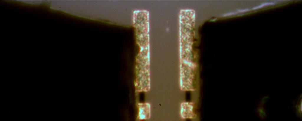
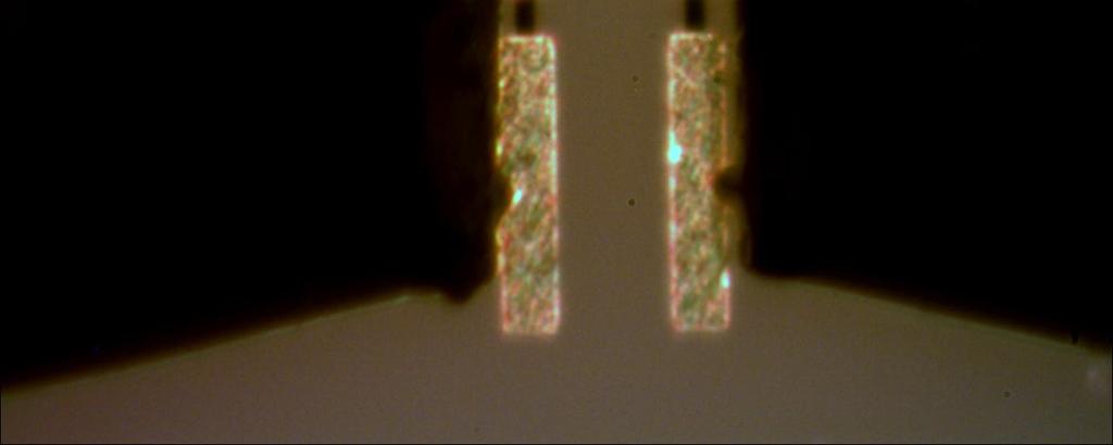
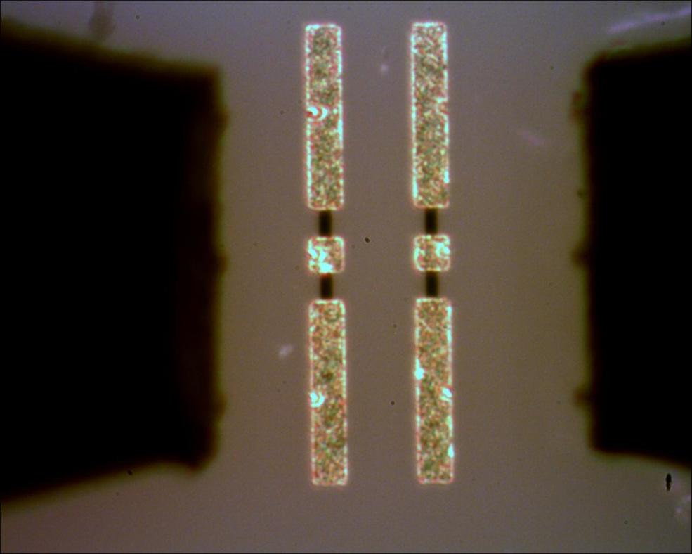
27 Probes in normal position lide 53 Probes misplaced lide 54 27

28 LRRM Experiment 1 lide 55 OLT based calibrations show much more noise in line measurement Choosing Calibration trategy Understanding of strengths and limitations is essential! Re-measuring of calibration standards verification! Method Application OLT Well defined conditions Frequencies < 40GHz OLR Rectangular configurations Double-side probing LRM Not recommended for wafer-level applications LRM+ Broadband on-wafer calibration LRRM Broadband I calibration lide 56 28
Calibration Uncertainty Estimation. at the Wafer Level
 Calibration Uncertainty Estimation for the S-Parameter S Measurements at the Wafer Level A. Rumiantsev SUSS MicroTec Test Systems GmbH Sussstr. 1, Sacka, D-01561, Germany a.rumiantsev@ieee.org Outline
Accuracy Estimations of S-Parameter Measurements at the Wafer-Level
 WORKSHOP WSF13 (EuMC/EuMIC) Determining Accuracy of Measurements at High Frequencies from Error to Uncertainty Accuracy Estimations of S-Parameter Measurements at the Wafer-Level H. Heuermann*, A. Rumiantsev**
Practical Considerations and Solutions for Temperature-Dependent S-Parameter Measurement for Accurate Parameter Extraction of
 Practical Considerations and Solutions for Temperature-Dependent S-Parameter Measurement for Accurate Parameter Extraction of Advanced RF Devices Gavin Fisher, Application Engineer Andrej Rumiantsev, Product
Ripple Method for Evaluating Residual Errors
 Ripple Method for Evaluating Residual Errors H. Heuermann Univ. of Applied Sciences Aachen, Institute of High Frequency Tech., Eupener Str. 7, D-5266 Aachen, Germany Heuermann@FH-Aachen.de Heuermann HF-Technik
Advancements in mm-wave On-Wafer Measurements: A Commercial Multi-Line TRL Calibration Author: Leonard Hayden Presenter: Gavin Fisher
 Advancements in mm-wave On-Wafer Measurements: A Commercial Multi-Line TRL Calibration Author: Leonard Hayden Presenter: Gavin Fisher The title of this section is A Commercial Multi-Line TRL Calibration
Unknown Thru Calibration Algorithm
 Introduction Calibration Kit SOL 1-Port SOLT 2-Port SOLR 2-Port Conclusion Unknown Thru Calibration Algorithm Short-Open-Load-Reciprocal SOLR T Reveyrand NVNA Users Forum - INMMiC 2018 Brive-la-Gaillarde,
A CALIBRATION PROCEDURE FOR TWO-PORT VNA WITH THREE MEASUREMENT CHANNELS BASED ON T-MATRIX
 Progress In Electromagnetics Research Letters, Vol. 29, 35 42, 2012 A CALIBRATION PROCEDURE FOR TWO-PORT VNA WITH THREE MEASUREMENT CHANNELS BASED ON T-MATRIX W. Zhao *, H.-B. Qin, and L. Qiang School
Broad-band space conservative on wafer network analyzer calibrations with more complex SOLT definitions
 University of South Florida Scholar Commons Graduate Theses and Dissertations Graduate School 24 Broad-band space conservative on wafer network analyzer calibrations with more complex SOLT definitions
Using the unknown-thru method for waveguide/coax systems with the 8510
 Using the unknown-thru method for waveguide/coax systems with the 8510 Jörgen Stenarson jorgen.stenarson@sp.se Unknown Thru algorithm Requires: four receiver VNA reciprocal thru standard switch corrected
Probe Tip Characterization Using Self-Calibration. Lab. RF Modeling
 Probe Tip Characterization Using Self-Calibration 1 Overview - equipment - how to determine probe S-parameter and parasitics (probe specific calibration coefficients) for different probes with only one
IN order to characterize the
 D E S G N F E A T U R E VERFY WAFER-PROBE REFERENCE PLANES FOR MMC TESTNG Three techniques for verification of planar calibration standards agree within ko.1 ps of electrical length. N order to characterize
De-embedding in High Speed Design
 DesignCon 2012 De-embedding in High Speed Design Dr. Don DeGroot, CCN & Andrews University Don@ccnlabs.com, 303-872-7700 Dr. Kaviyesh Doshi, LeCroy Corporation Kaviyesh.Doshi@lecroy.com, 845-425-2000 David
Lecture 13. Vector Network Analyzers and Signal Flow Graphs
 HP8510 Lecture 13 Vector Network Analyzers and Signal Flow Graphs 1 Vector Network Analyzers HP8510 Agilent 8719ES R&S ZVA67 VNA 2 ports, 67 GHz port 1 port 2 DUT Agilent N5247A PNA-X VNA, 4 ports, 67
Advances in Radio Science
 Advances in Radio Science 2003 1: 1 8 c Copernicus GmbH 2003 Advances in Radio Science Uncertainty of VNA S-parameter measurement due to non-ideal TMSO or LMSO calibration standards U. Stumper Physikalisch-Technische
WE PRESENT an iterative algorithm, which we first
 IEEE TRANSACTIONS ON MICROWAVE THEORY AND TECHNIQUES, VOL. 51, NO. 12, DECEMBER 2003 2391 An Optimal Vector-Network-Analyzer Calibration Algorithm Dylan F. Williams, Fellow, IEEE, Jack C. M. Wang, and
Transmission-Reflection Method to Estimate Permittivity of Polymer
 Transmission-Reflection Method to Estimate Permittivity of Polymer Chanchal Yadav Department of Physics & Electronics, Rajdhani College, University of Delhi, Delhi, India Abstract In transmission-reflection
An On-Wafer Deembedding Procedure for Devices under Measurement with Error-Networks Containing Arbitrary Line Lengths
 An On-Wafer Deembedding Procedure for Devices under Measurement with Error-Networks Containing Arbitrary Line Lengths Thomas-Michael Winkel, Lohit Sagar Dutta, Hartmut Grabinski Laboratorium fur Informationstechnologie,
TDR, S-Parameters & Differential Measurements. TDR, S-Parameters & Differential Measurements
 DR, -Parameters & Differential Measurements Agenda Introduction DR theory of operation Real Example: amtec Golden tandard Board ingle Ended Impedance Coupling Effects Odd & Even Modes Differential Impedance
This section reviews the basic theory of accuracy enhancement for one-port networks.
 Vector measurements require both magnitude and phase data. Some typical examples are the complex reflection coefficient, the magnitude and phase of the transfer function, and the group delay. The seminar
LAB MANUAL EXPERIMENT NO. 7
 LAB MANUAL EXPERIMENT NO. 7 Aim of the Experiment: Concept of Generalized N-port scattering parameters, and formulation of these parameters into 2-port reflection and transmission coefficients. Requirement:
Contents. Transmission Lines The Smith Chart Vector Network Analyser (VNA) ü structure ü calibration ü operation. Measurements
 ü structure ü calibration ü operation. Measurements") Contents Transmission Lines The Smith Chart Vector Network Analyser (VNA) ü structure ü calibration ü operation Measurements Göran Jönsson, EIT 2015-04-27 Vector Network Analysis 2 Waves on Lines If the
Contents Transmission Lines The Smith Chart Vector Network Analyser (VNA) ü structure ü calibration ü operation Measurements Göran Jönsson, EIT 2015-04-27 Vector Network Analysis 2 Waves on Lines If the
Impact of adapters on LISN's input impedance calibration: How to improve accuracy and reliability of the measurements? Part 2
 Impact of adapters on LISN's input impedance calibration: How to improve accuracy and reliability of the measurements? Part 2 François. ZIADE, Miha. KOKALJ Workshop EMC Europe 2016 Outline Objective :
Power Splitter Characterisation EM Day
 Power Splitter Characterisation EM Day 9 November 007 James Miall (james.miall@npl.co.uk) National Physical Laboratory Teddington, UK Tuesday, 11 December 007 Contents Why we need to measure power splitters
Two Port Networks. Definition of 2-Port Network A two-port network is an electrical network with two separate ports for input and output
 Two Port Networks Definition of 2-Port Network A two-port network is an electrical network with two separate ports for input and output What is a Port? It is a pair of terminals through which a current
ECE 546 Lecture 13 Scattering Parameters
 ECE 546 Lecture 3 Scattering Parameters Spring 08 Jose E. Schutt-Aine Electrical & Computer Engineering University of Illinois jesa@illinois.edu ECE 546 Jose Schutt Aine Transfer Function Representation
Calibrating On-Wafer Probes to the Probe Tips
 Calibrating On-Wafer Probes to the Probe Tips Dylan F. Williams and Roger B. Marks National Institute of Standards and Technology 325 Broadway, Boulder, CO 80303 Abstract This paper investigates the accuracy
Waves on Lines. Contents. ! Transmission Lines! The Smith Chart! Vector Network Analyser (VNA) ! Measurements
 ! Measurements") Waves on Lines If the wavelength to be considered is significantly greater compared to the size of the circuit the voltage will be independent of the location. amplitude d! distance but this is not true
Waves on Lines If the wavelength to be considered is significantly greater compared to the size of the circuit the voltage will be independent of the location. amplitude d! distance but this is not true
SPARQ S-Parameter Measurements with Impulse Response Time Limiting
 SPARQ S-Parameter Measurements with Impulse Response Time Limiting Dr. Alan Blankman, Product Manager Summary Beginning with version 6.5.0.2 of the SPARQ software, users have the option of limiting the
Contents. Transmission Lines The Smith Chart Vector Network Analyser (VNA) ü structure ü calibration ü operation. Measurements
 ü structure ü calibration ü operation. Measurements") Contents Transmission Lines The Smith Chart Vector Network Analyser (VNA) ü structure ü calibration ü operation Measurements Göran Jönsson, EIT 2017-05-12 Vector Network Analysis 2 Waves on Lines If the
Contents Transmission Lines The Smith Chart Vector Network Analyser (VNA) ü structure ü calibration ü operation Measurements Göran Jönsson, EIT 2017-05-12 Vector Network Analysis 2 Waves on Lines If the
A Multi-Line De-Embedding Technique for mm-wave CMOS Circuits
 A Multi-Line De-Embedding Technique for mm-wave CMOS Circuits Naoki Takayama, Kota Matsushita, Shogo Ito, Ning Li, Keigo Bunsen Kenichi Okada, and Akira Tokyo Institute of Technology, Japan Outline 2 Background
TRL algorithm to de-embed a RF test fixture
 TRL algorithm to de-embed a RF test fixture T. Reveyrand University of Colorado - Boulder ECEE department 425 UCB Boulder, Colorado 80309 USA July 2013 1 TRL Standards THRU and LINE Measurements T OUT
OpenWeatherMap Module
 OpenWeatherMap Module Installation and Usage Guide Revision: Date: Author(s): 1.0 Friday, October 13, 2017 Richard Mullins Contents Overview 2 Installation 3 Import the TCM in to accelerator 3 Add the
Load-pull measurement of transistor negative input impedance
 Jan Verspecht bvba Gertrudeveld 15 1840 Steenhuffel Belgium email: contact@janverspecht.com web: http://www.janverspecht.com Load-pull measurement of transistor negative input impedance Fabien De Groote,
O P E R A T I N G M A N U A L
 OPERATING MANUAL WeatherJack OPERATING MANUAL 1-800-645-1061 The baud rate is 2400 ( 8 bits, 1 stop bit, no parity. Flow control = none) To make sure the unit is on line, send an X. the machine will respond
Keysight Technologies Measurement Uncertainty of VNA Based TDR/TDT Measurement. Application Note
 Keysight Technologies Measurement Uncertainty of VNA Based TDR/TDT Measurement Application Note Table of Contents Introduction... 3 S-parameter measurement uncertainty of VNA... 4 Simplification of systematic
Analytic Solutions for Periodically Loaded Transmission Line Modeling
 Analytic Solutions for Periodically Loaded Transmission Line Modeling Paul G. Huray, huray@sc.edu Priya Pathmanathan, Intel priyap@qti.qualcomm.com Steve Pytel, Intel steve.pytel@ansys.com April 4, 2014
IMPEDANCE MATCHING CAPABILITY OF NOVEL SOCKET CONTACTOR DESIGN USING VARIABLE OPEN STUBFOR RF PACKAGING TESTING
 Progress In Electromagnetics Research, Vol. 113, 67 82, 2011 IMPEDANCE MATCHING CAPABILITY OF NOVEL SOCKET CONTACTOR DESIGN USING VARIABLE OPEN STUBFOR RF PACKAGING TESTING S.-M. Wu and K. Y. Wang Department
ECE414/514 Electronics Packaging Spring 2012 Lecture 6 Electrical D: Transmission lines (Crosstalk) Lecture topics
 Lecture topics") ECE414/514 Electronics Packaging Spring 2012 Lecture 6 Electrical D: Transmission lines (Crosstalk) James E. Morris Dept of Electrical & Computer Engineering Portland State University 1 Lecture topics
ECE414/514 Electronics Packaging Spring 2012 Lecture 6 Electrical D: Transmission lines (Crosstalk) James E. Morris Dept of Electrical & Computer Engineering Portland State University 1 Lecture topics
Contents. ! Transmission Lines! The Smith Chart! Vector Network Analyser (VNA) ! Measurements. ! structure! calibration! operation
 ! Measurements. ! structure! calibration! operation") Contents! Transmission Lines! The Smith Chart! Vector Network Analyser (VNA)! structure! calibration! operation! Measurements Göran Jönsson, EIT 2009-11-16 Network Analysis 2! Waves on Lines! If the wavelength
Contents! Transmission Lines! The Smith Chart! Vector Network Analyser (VNA)! structure! calibration! operation! Measurements Göran Jönsson, EIT 2009-11-16 Network Analysis 2! Waves on Lines! If the wavelength
Application Note. Electrical. Optical
 Application Note Electrical Vector Network Analyzer Port 1 Port 2 Electrical Electrical MX40G E-O Converter Optical O-E Device Under Test Using the MX40G: De Embedding Procedures One of the primary applications
THE search for higher accuracy in measurements of S-
 IEEE TRANSACTIONS ON MICROWAVE THEORY AND TECHNIQUES, VOL. XX, NO. XX, JANUARY 2XX 1 One-Port Direct/Reverse Method for Characterizing VNA Calibration Standards Raul A. Monsalve, Member, IEEE, Alan E.
VNA Tools II S-parameter uncertainty calculation
 VA Tools II S-parameter uncertainty calculation Michael Wollensack METAS 5. May 0 Michael Wollensack METAS Outline Introduction VA Measurement Model Database Uncertainty Visualization Results Michael Wollensack
Microwave Impedance Measurement for Nanoelectronics
 276 M. RNDUS, K. HOFFMNN, MICROWVE IMPEDNCE MESUREMEN FOR NNOELECRONICS Microwave Impedance Measurement for Nanoelectronics Martin RNDUS, Karel HOFFMNN Dept. of Electromagnetic Field, Czech echnical University
Error Correction in Vector Network Analyzers
 Error Correction in Vector Network Analyzers Thomas C. Baier, DG8SAQ May 19, 2009 Abstract This article describes systematic errors encountered in vector network analysis and how they can be mathematically
Quantifying and Verifying trace stability of vector network analyzers at frequencies below 1GHz
 1 Quantifying and Verifying trace stability of vector network analyzers at frequencies below 1GHz Hamdi Mani, Chris Groppi, Judd Bowman Abstract we describe measurements done to check the low frequency
Microwave Network Analysis
 Microwave Network Analysis S R Zinka zinka@hyderabadbits-pilaniacin Department of Electrical & Electronics Engineering BITS Pilani, Hyderbad Campus May 7, 2015 RF & Microwave Engineering, Dept of EEE,
MFJ 259/259B Operation & Simplified Calibration
 MFJ 259/259B Operation & Simplified Calibration Bill Leonard N0CU 1 March 2014 What Is An MFJ-259 MFJ lists it as a HF/VHF SWR Analyzer It is essentially a ONE PORT NETWORK ANALYZER Measures the electrical
PAD MODELING BY USING ARTIFICIAL NEURAL NETWORK
 Progress In Electromagnetics Research, PIER 74, 167 180, 2007 PAD MODELING BY USING ARTIFICIAL NEURAL NETWORK X. P. Li School of Telecommunication Engineering Beijing University of Posts and Telecommunications
S-PARAMETER QUALITY METRICS AND ANALYSIS TO MEASUREMENT CORRELATION
 S-PARAMETER QUALITY METRICS AND ANALYSIS TO MEASUREMENT CORRELATION VNA Measurement S-Parameter Quality Metrics 2 S-Parameter Quality Metrics Quality is important Reciprocity Forward and reverse transmission
ECE Microwave Engineering
 ECE 537-635 Microwave Engineering Fall 8 Prof. David R. Jackson Dept. of ECE Adapted from notes by Prof. Jeffery T. Williams Notes Power Dividers and Circulators Power Dividers and Couplers A power divider
New Methods for Measuring the Effective Source Reflection Coefficient of Microwave Generators. Jens Leinhos, Thomas Reichel and Jochen Simon
 New Methods for Measuring the Effective Source Reflection Coefficient of Microwave Generators Jens Leinhos, Thomas Reichel and Jochen Simon Contents l l l l l l l l l Introduction Measurement Procedures
Athena Visual Software, Inc. 1
 Athena Visual Studio Visual Kinetics Tutorial VisualKinetics is an integrated tool within the Athena Visual Studio software environment, which allows scientists and engineers to simulate the dynamic behavior
Models in the N1500A and 85071E Materials Measurement Software
 Nicholson- Ross -Weir, NRW Originally developed by Nicholson and Ross, and later adapted to automatic network analyzers by Weir to calculate permittivity and permeability from transmission and reflection
Electric Circuit Theory
 Electric Circuit Theory Nam Ki Min nkmin@korea.ac.kr 010-9419-2320 Chapter 18 Two-Port Circuits Nam Ki Min nkmin@korea.ac.kr 010-9419-2320 Contents and Objectives 3 Chapter Contents 18.1 The Terminal Equations
Estimation of Complex and Linear Uncertainities in S-Parameter Measurements for Metrology Applications
 International Journal of Electromagnetics and Applications 01, (5): 85-104 DOI: 10.593/j.ijea.01005.0 Estimation of Complex and inear Uncertainities in S-Parameter Measurements for Metrology Applications
What s Your (real or imaginary) LCR IQ?
 LCR IQ?") Chroma Systems Solutions, Inc. What s Your (real or imaginary) LCR IQ? 11021, 11025 LCR Meter Keywords:. Impedance, Inductance, Capacitance, Resistance, Admittance, Conductance, Dissipation Factor, 4-Terminal
Chroma Systems Solutions, Inc. What s Your (real or imaginary) LCR IQ? 11021, 11025 LCR Meter Keywords:. Impedance, Inductance, Capacitance, Resistance, Admittance, Conductance, Dissipation Factor, 4-Terminal
Front End Electronics Internal Noise Source Characterization
 Front End Electronics Internal Noise Source Characterization Joe Brendler and R.H. Tillman May 14, 2015 Contents 1 Introduction 2 2 System Model 2 3 Measurement Process 3 3.1 G r Measurement....................................
Progress In Electromagnetics Research M, Vol. 20, 73 80, 2011
 Progress In Electromagnetics Research M, Vol. 20, 73 80, 2011 COPLANAR METAMATERIAL MICRO-RESONATOR S. Nemer 1, 2, *, B. Sauviac 1, B. Bayard 1, J. J. Rousseau 1, C. Nader 2, J. Bechara 2, and A. Khoury
Capacitor in the AC circuit with Cobra3
 Capacitor in the AC circuit with Cobra3 LEP Related Topics Capacitance, Kirchhoff s laws, Maxwell s equations, AC impedance, Phase displacement Principle A capacitor is connected in a circuit with a variable-frequency
Ansoft HFSS 3D Boundary Manager Sources
 Lumped Gap Defining s Voltage and Current When you select Source, you may choose from the following source types: Incident wave Voltage drop Current Magnetic bias These sources are available only for driven
Passive components in MMIC technology
 Passive components in MMIC technology Evangéline BENEVENT Università Mediterranea di Reggio Calabria DIMET 1 Introduction Design cycle of passive components in MMIC technology Passive components in MMIC
Open-Thru de-embedding for Graphene RF devices
 Open-Thru de-embedding for Graphene RF devices Giancarlo Vincenzi, Georgios Deligeorgis, Fabio Coccetti, Patrick Pons To cite this version: Giancarlo Vincenzi, Georgios Deligeorgis, Fabio Coccetti, Patrick
Coplanar Microwave Integrated Circuits
 Ingo Wolff Coplanar Microwave Integrated Circuits Verlagsbuchhandlung Dr. Wolff GmbH Content Chapter I. 1.1 Chapter II. II. 1 n.1.1 n.1.2 n.1.3 n.1.3.1 n.1.3.2 n.2 n.2.1 n.2.2 n.2.3 n.2.4 n.2.5 n.2.6 n.2.7
DESIGN METHODOLOGY OF MULTI-FREQUENCY UN- EQUAL SPLIT WILKINSON POWER DIVIDERS USING TRANSMISSION LINE TRANSFORMERS
 Progress In Electromagnetics Research B, Vol. 22, 1 21, 2010 DESIGN METHODOLOGY OF MULTI-FREQUENCY UN- EQUAL SPLIT WILKINSON POWER DIVIDERS USING TRANSMISSION LINE TRANSFORMERS A. Qaroot and N. Dib Electrical
ncounter PlexSet Data Analysis Guidelines
 ncounter PlexSet Data Analysis Guidelines NanoString Technologies, Inc. 530 airview Ave North Seattle, Washington 98109 USA Telephone: 206.378.6266 888.358.6266 E-mail: info@nanostring.com Molecules That
Graphical User Interfaces for Emittance and Correlation Plot. Henrik Loos
 Graphical User Interfaces for Emittance and Correlation Plot Common GUI Features Overview Files Configs Measure Data Point Export Common GUI Features Save Saves the present data. Auto-generated file name
Software BioScout-Calibrator June 2013
 SARAD GmbH BioScout -Calibrator 1 Manual Software BioScout-Calibrator June 2013 SARAD GmbH Tel.: ++49 (0)351 / 6580712 Wiesbadener Straße 10 FAX: ++49 (0)351 / 6580718 D-01159 Dresden email: support@sarad.de
FRAM V5.2. Plutonium and Uranium Isotopic Analysis Software
 V5.2 Plutonium and Uranium Isotopic Analysis Software Advanced Isotopic Ratio Analysis Software for HPGe Gamma-Ray Spectra Analyzes Pu, and a wide variety of heterogeneous samples containing Pu, Am, U,
Experiment P43: RC Circuit (Power Amplifier, Voltage Sensor)
") PASCO scientific Vol. 2 Physics Lab Manual: P43-1 Experiment P43: (Power Amplifier, Voltage Sensor) Concept Time SW Interface Macintosh file Windows file circuits 30 m 700 P43 P43_RCCI.SWS EQUIPMENT NEEDED
PASCO scientific Vol. 2 Physics Lab Manual: P43-1 Experiment P43: (Power Amplifier, Voltage Sensor) Concept Time SW Interface Macintosh file Windows file circuits 30 m 700 P43 P43_RCCI.SWS EQUIPMENT NEEDED
A UNEQUAL COUPLED-LINE WILKINSON POWER DI- VIDER FOR ARBITRARY TERMINATED IMPEDANCES
 Progress In Electromagnetics Research, Vol. 117, 181 194, 211 A UNEQUAL COUPLED-LINE WILKINSON POWER DI- VIDER FOR ARBITRARY TERMINATED IMPEDANCES Y. Wu * and Y. Liu School of Electronic Engineering, Beijing
Double Star Observations
 Double Star Observations Canopus now includes enhanced features for measurnig double stars. This includes easier setting of the reference position (the primary star) as well as recording the observations
S-Parameter Measurements
 Progress In Electromagnetics Research, Vol 144, 303 318, 014 Influence of SOLT Calibration Standards on Multiport VNA S-Parameter Measurements Wei Zhao *, Jiankang Xiao, and Hongbo Qin Abstract For the
ECEN689: Special Topics in High-Speed Links Circuits and Systems Spring 2012
 ECEN689: pecial Topics in High-peed Links Circuits and ystems pring 01 Lecture 3: Time-Domain Reflectometry & -Parameter Channel Models am Palermo Analog & Mixed-ignal Center Texas A&M University Announcements
Boundary and Excitation Training February 2003
 Boundary and Excitation Training February 2003 1 Why are They Critical? For most practical problems, the solution to Maxwell s equations requires a rigorous matrix approach such as the Finite Element Method
NIST DTSA-II ( Son of DTSA ): Step-by-Step
: Step-by-Step") NIST DTSA-II ( Son of DTSA ): Step-by-Step Dale E. Newbury (grateful user) National Institute of Standards and Technology Gaithersburg, MD 20899-8370 NIST-NIH Desktop Spectrum Analyzer (DTSA) Spectral
NIST DTSA-II ( Son of DTSA ): Step-by-Step Dale E. Newbury (grateful user) National Institute of Standards and Technology Gaithersburg, MD 20899-8370 NIST-NIH Desktop Spectrum Analyzer (DTSA) Spectral
CHARACTERIZATION OF MAGNETICALLY LOADED MICROWAVE ABSORBERS
 Progress In Electromagnetics Research B, Vol. 33, 277 289, 2011 CHARACTERIZATION OF MAGNETICALLY LOADED MICROWAVE ABSORBERS I. Zivkovic * and A. Murk Institute of Applied Physics, University of Bern Siedlerstrasse
UNIT I ELECTROSTATIC FIELDS
 UNIT I ELECTROSTATIC FIELDS 1) Define electric potential and potential difference. 2) Name few applications of gauss law in electrostatics. 3) State point form of Ohm s Law. 4) State Divergence Theorem.
NTE74HC299 Integrated Circuit TTL High Speed CMOS, 8 Bit Universal Shift Register with 3 State Output
 NTE74HC299 Integrated Circuit TTL High Speed CMOS, 8 Bit Universal Shift Register with 3 State Output Description: The NTE74HC299 is an 8 bit shift/storage register with three state bus interface capability
Accurate Modeling of Spiral Inductors on Silicon From Within Cadence Virtuoso using Planar EM Simulation. Agilent EEsof RFIC Seminar Spring 2004
 Accurate Modeling of Spiral Inductors on Silicon From Within Cadence Virtuoso using Planar EM Simulation Agilent EEsof RFIC Seminar Spring Overview Spiral Inductor Models Availability & Limitations Momentum
Smith Chart Tuning, Part I
 Smith Chart Tuning, Part I Donald Lee Advantest Test Cell Innovations, SOC Business Unit January 30, 2013 Abstract Simple rules of Smith Chart tuning will be presented, followed by examples. The goal is
Become a Microprobe Power User Part 2: Qualitative & Quantitative Analysis
 Become a Microprobe Power User Part 2: Qualitative & Quantitative Analysis Mike Spilde Spring IOM Seminar February 5, 2008 Qualitative Analysis Why use qualitative scans? Elemental ID (especially trace
SerDes_Channel_Impulse_Modeling_with_Rambus
 SerDes_Channel_Impulse_Modeling_with_Rambus Author: John Baprawski; John Baprawski Inc. (JB) Email: John.baprawski@gmail.com Web sites: https://www.johnbaprawski.com; https://www.serdesdesign.com Date:
Microwave Network Analysis
 Prof. Dr. Mohammad Tariqul Islam titareq@gmail.my tariqul@ukm.edu.my Microwave Network Analysis 1 Text Book D.M. Pozar, Microwave engineering, 3 rd edition, 2005 by John-Wiley & Sons. Fawwaz T. ILABY,
Chapter 11: WinTDR Algorithms
 Chapter 11: WinTDR Algorithms This chapter discusses the algorithms WinTDR uses to analyze waveforms including: Bulk Dielectric Constant; Soil Water Content; Electrical Conductivity; Calibrations for probe
Lecture 12. Microwave Networks and Scattering Parameters
 Lecture Microwave Networs and cattering Parameters Optional Reading: teer ection 6.3 to 6.6 Pozar ection 4.3 ElecEng4FJ4 LECTURE : MICROWAE NETWORK AND -PARAMETER Microwave Networs: oltages and Currents
Topics to be Covered. capacitance inductance transmission lines
 Topics to be Covered Circuit Elements Switching Characteristics Power Dissipation Conductor Sizes Charge Sharing Design Margins Yield resistance capacitance inductance transmission lines Resistance of
Measure - Conductivity STANDARD Last std: Sep 10:17 am. Touch meas to measure sample. Touch std to access standardize mode ATC. 25.
 Conductivity Operation accumet Measure - Conductivity us/cm channel 1 STANDARD Last : Sep 17 @ 10:17 am The meter will automatically convert conductivity values to salinity, total dissolved solids (TDS),
Measuring Complex Permittivity, Permeability, or Sheet Impedance of Materials at Microwave Frequencies with a Free-Space Spot Probe System
 1. Scope Measuring Complex Permittivity, Permeability, or Sheet Impedance of Materials at Microwave Frequencies with a Free-Space Spot Probe System 1.1 This test method covers a procedure for determining
Technique for the electric and magnetic parameter measurement of powdered materials
 Computational Methods and Experimental Measurements XIV 41 Technique for the electric and magnetic parameter measurement of powdered materials R. Kubacki,. Nowosielski & R. Przesmycki Faculty of Electronics,
Determining Characteristic Impedance and Velocity of Propagation by Measuring the Distributed Capacitance and Inductance of a Line
 Exercise 2-1 Determining Characteristic Impedance and Velocity EXERCISE OBJECTIVES Upon completion of this exercise, you will know how to measure the distributed capacitance and distributed inductance
 Humidity, and Dew Point Data Logger with LCD ORDERING INFORMATION Standard Data Logger (Data Logger, Software on CD, Battery) Replacement Battery EL-USB-2-LCD BAT 3V6 1/2AA FEATURES 0 to 100 measurement
VNA error models: Comments on EURAMET/cg-12/v.01
 Industrial Research Limited Report 2444 VNA error models: Comments on EURAMET/cg-12/v.01 B. D. Hall Measurement Standards Laboratory of New Zealand Lower Hutt, New Zealand 16 June 2010, (Replaces 5 May
Sophomore Physics Laboratory (PH005/105)
") CALIFORNIA INSTITUTE OF TECHNOLOGY PHYSICS MATHEMATICS AND ASTRONOMY DIVISION Sophomore Physics Laboratory (PH5/15) Analog Electronics Active Filters Copyright c Virgínio de Oliveira Sannibale, 23 (Revision
CALIFORNIA INSTITUTE OF TECHNOLOGY PHYSICS MATHEMATICS AND ASTRONOMY DIVISION Sophomore Physics Laboratory (PH5/15) Analog Electronics Active Filters Copyright c Virgínio de Oliveira Sannibale, 23 (Revision
E102. Study of the magnetic hysteresis
 E102. Study of the magnetic hysteresis 1. Introduction Due to the behavior in a magnetic field, the materials can be divided into three groups: diamagnets (weakly repelled by a magnet), paramagnets (weakly
SuperCELL Data Programmer and ACTiSys IR Programmer User s Guide
 SuperCELL Data Programmer and ACTiSys IR Programmer User s Guide This page is intentionally left blank. SuperCELL Data Programmer and ACTiSys IR Programmer User s Guide The ACTiSys IR Programmer and SuperCELL
ECE 451 Transmission Lines & Packaging
 Transmission Lines & Packaging Jose E. Schutt-Aine Electrical & Computer Engineering University of Illinois jose@emlab.uiuc.edu 1 Radio Spectrum Bands The use of letters to designate bands has long ago
Frequency Multiplexing Tickle Tones to Determine Harmonic Coupling Weights in Nonlinear Systems
 Charles Baylis and Robert J. Marks II, "Frequency multiplexing tickle tones to determine harmonic coupling weights in nonlinear systems,'' Microwave Measurement Symposium (ARFTG), 2011 78th ARFTG pp.1-7,
INF5481 RF Circuit, Theory and Design Assignment #3
 INF548 RF Circuit, Theory and Design ssignment #3 Problem We have the two port network in figure, which is a cascade of two identical networks consisting of a single shunt and series impedance. Find the
Single- and Multiport Networks. RF Electronics Spring, 2018 Robert R. Krchnavek Rowan University
 Single- and Multiport Networks RF Electronics Spring, 208 Robert R. Krchnavek Rowan University Objectives Generate an understanding of the common network representations of Z, Y, h, and ABCD. To be able