LISA Pathfinder / SMART-2
|
|
|
- Berniece Anderson
- 6 years ago
- Views:
Transcription
1 LISA Pathfinder / SMART-2 LISA Pathfinder and the LTP experiment 38 th ESLAB Symposium for the ESA LPF Team: S.Vitale, K.Danzmann, E.Balaguer, U.Gageur, C.Garcia, L.Giulicchi, R.Grünagel, M.Landgraf, P.Maldari, D.Nicolini, L.Stagnaro, C.Tirabassi ESA-ESTEC 12 July 2004
2 The Mission Statement Smart-2 is a technology demonstration mission for LISA -> LISA Pathfinder Two technology packages will be embarked: The European LISA Test-flight Package (LTP) The America Disturbance Reduction System (DRS) A Drag Free Attitude Control System (DFACS) In addition, a number of European micropropulsion technologies will be flight demonstrated for the first time: Field Emission Electrical Propulsion (FEEP) thrusters micronewton proportional Cold Gas thrusters and drive electronics

3 LPF: Mission Goal The technologies for LISA cannot be proven on the ground, thus ESA has conceived SMART-2, the LISA Pathfinder Mission SMART-2 has one fundamental goal: To be able to demonstrate the nearperfect free-fall of a Test Mass located inside the body of the spacecraft by limiting the spectral density of accelerations at the test mass to: between 1 and 30 mhz The basic idea is that of squeezing one LISA interferometer arm from 5 *10 6 km to a few centimetres (the so-called LISA Test Package) on-board a small spacecraft. A similar system ( DRS ) is provided by NASA
4 LISA vs. LPF range
5 The Mother of all Noises a Force on æ spacecraft ö ç } f F T/ M 2 S C = + w ç x + { m { ç { Mw Sensor noise { fb Parasitic stiffness Force on Test-Mass ç Drag-free è gain ø noise p n 2 Re lative diplacement TM wrt S/C
6 Noise identification IS readout displacement noise Thermal effects Cross Talk Electro-Magnetic disturbances generated within the spacecraft Magnetic disturbances due to interplanetary field fluctuation Random charging Laser readout noise and thermal distortion Laser radiation pressure fluctuation Fluctuation of local gravitational field due to distortion of the system components
7 Parasitic coupling DC-voltage AC-voltage Charge Magnetic stiffness Gravitational gradient Low frequency suspension
8 Disturbance Forces External Forces on the spacecraft include: Thruster force, including noise Difference in gravitational acceleration between test mass and spacecraft centre of mass Solar radiation pressure Interaction with planetary magnetic fields etc. Internal Forces acting on the proof mass and the spacecraft include Thermal noise, radiation pressure Pressure fluctuations, outgassing Electrostatic, magnetic, gravitational fields Force that arises from sensor noise feeding into thruster commands and hence resulting in random thrust noise
9 Operative Modes Off Mode Safe Mode Positioning Mode Accelerometer Mode M1 M3 M4
10 M1 The spacecraft follows TM1 along the sensitive axis, by using the capacitive sensor measurement. TM2 is controlled along the sensitive axis by the electro-static suspension loop, by using the capacitive sensor measurement. Other DoF are controlled by a combination of thrusters and electrostaticsuspension, in and out of band. The main metrology signal is the relative position of TM1 vs. TM2 as measured by the interferometer. TM1 and TM2 shall be interchangeable. Some test runs are required by using the interferometer output instead of the capacitive readouts.
11 M3 As M1 but TM2 is made to follows TM1 along the sensitive axis, by using the capacitive actuation. Laser noise Baselinedistortion é w ê fb 2 æ s ö æ 2 s w p,1 + w ö p,2 ê lsr n, laser ç 2 p, 2 2 w ç fb wfb 2 D x = x s 1+ + Dx w ( s + w fb )( s + wlfs ) ê è ø è ø êë Difference x of force Difference of parasitic coupling 2 x, x,1 æ ö ( p2 p1 ) m ç w fb f f s w - w è ø = Test- mass / Spacecraft relative dispacement ù ú æ F ö S/ C ú ç xn,1 + 2 Mw ú è fb ø úúû S / C
12 M4 y LTP TM2 DRS y DRS TM2 LTP TM1 DRS LTP TM1 45 x LTP x DRS
13 M4 Drag free along the x-axis of the LTP is controlled by the LTP x-axis capacitive sensor readout of the LTP TM1 (actuation normal to the DRS x-axis). Drag free along the x-axis of the DRS is controlled by the DRS x-axis capacitive sensor readout of the DRS TM1 (actuation normal to the LTP x-axis). Attitude along f (rotation around the common z-axis) is controlled within the MBW by the differential y-axis output of the IS1 and IS2 of LTP. TM1 and TM2 of the LTP are subject, along the y-axis, to a low frequency suspension loop driven by their common mode displacement.
14 Test Runs 12 Main Runs. A Test Run is NOT a single demonstration sequence: 1. Measurement of total acceleration (M1) 2. Measurement of acceleration noise (M3) 3. Measurement of internal forces (M1 and M3) 4. Measurement of stiffness (M3) 5. Measurement of cross-talk (M3) 6. Test of continuous charge charge measurement (M3) 7. Test of continuous discharge (M3) 8. Drift mode 9. Acceleration noise at different working points (M3) 10. Noise measurement below the MBW (M1) 11. Sensitivity to magnetic field and thermal gradient (M3) 12. Joint operations with the DRS
15 Joint Operations Simultaneous operation of LTP and DRS at full functionality for both packages. Use of the DRS test masses as a source of gravitational signal for the LTP. Use of the LTP test masses as a source of gravitational signal for the DRS. 2-axes 2-test-masses control with full functionality for both packages and one axis controlled by DRS (mode M4).
16 Mode Transition Accelerometer Mode Standard FDIR M1-perf M1-optical M3 M1-init M1-drift LTP Science Mode M4 Joint LISA Mode

17 M1 Differential Acceleration Performance needs to be traded with robustness of x 2 suspension controller

18 M1 Diff.Acc Time-Domain

19 M3 Differential Acceleration very small violation, can be removed by using more optical readouts
20 LISA Pathfinder / SMART-2 Spacecraft Configuration Material from Prime Contractor EADS Astrium Ltd. (UK)
 Overall dimensions are 2836 mm high (plus 276 mm protrusion into LVA) and 2100 mm diameter (plus 30 mm antenna protrusion beyond")
21 System Overview LISA Pathfinder Launch Composite consists of two modules Science Spacecraft Propulsion Module Current Predicted Maximum Mass is kg. Maximum Launch Mass is 1910 kg (constrained by Rockot capability) Overall dimensions are 2836 mm high (plus 276 mm protrusion into LVA) and 2100 mm diameter (plus 30 mm antenna protrusion beyond this) Compliant with the envelopes of both Dnepr and Rockot

22 The Science Spacecraft The science spacecraft carries the the LTP and DRS, the micro-propulsion systems and the drag free control system. Total mass about 470kg The inertial sensor core assemblies are mounted in a dedicated compartment within the central cylinder. DRS Colloid thrusters are mounted on opposing outer panels. Payload electronics and spacecraft units are accommodated as far away as possible from the sensors to minimise gravitational, thermal and magnetic disturbance. The FEEP and cold-gas micropropulsion assemblies are arranged to provide full control in all axes.


23 Science Spacecraft Central Cylinder 788 mm x 900 mm long mounting:- the LTP Optical Bench and the DRS Sensor Assembly the Propulsion Module I/F Eight Shear Walls 864 high, 571 or 510 wide mounting:- LTP Electrical Boxes, DRS Electronics Assembly all subsystem elements not requiring external visibility Eight External Walls 864 high mounting:- the thruster assemblies (2 Collodial, 3 Cold Gas & 3 FEEP) the AOCS sensors (star trackers & eclipse detectors) Low Gain and Medium Gain antennas Top Floor 2100 mounting Solar Array and Sun Sensors Lower Closure Floors. Central Cylinder, all panels carbon fibre skins, aluminium honeycomb cores for low mass, high stiffness, low distortion Overall Dimensions 985 mm high, 2100 mm diameter (plus 30 mm antenna protrusion beyond this) Current Predicted Maximum Mass kg.
24 Disturbance reduction Disturbances on the science spacecraft to be actively minimised by design: No mechanisms on the science spacecraft Known mass No actively controlled thermal elements (does not preclude heaters, but does preclude thermostats) Fixed sunshield, limited solar aspect angle No liquids


25 Managing Self gravity DC force fields on spacecraft contribute to differential acceleration DC forces, stiffness and noise The main internal contributors to the DC force are selfgravity, magnetic and electrostatic fields. Self gravity most difficult Dedicated central compartment isolates DRS & LTP inertial sensors - DRS is largest disturbance on LTP Compensation masses will be required inside LTP and DRS. Masses designed by PI for LTP & DRS at same time Must be defined early Gravitational modelling required Detailed mass models of everything Fix configuration and masses early Spacecraft provides final compensation Mass critical, so adding extra mass not an option (image from Trento University:)
26 Gravity Budget Max differential acceleration between TMs specified in LTP Science Requirements (LTPA-UTN-ScRD-Iss002-Rev1) Three main contributors are the inertial sensor (IS), the LTP and the spacecraft (including DRS). DRS and LTP largest external contributors to each other. Analysis performed using spreadsheet model & current spacecraft configuration shows uncompensated acceleration values about 3x10⁻⁸ m/s 2 - will require compensation Current requirements are: Differential Acceleration due to gravity(m/s 2 ) x 10-9 Axis Total IS LTP Spacecraft DFx/M DFy/M DFz/M

 2152 mm maximum diameter (across tank shells) Current Predicted Maximum Mass is 1409.2 kg, including 1207.7 kg of propellant.")
27 Propulsion Module Single design compatible with launch on Rockot or Dnepr Propulsion module separates from the science spacecraft prior to drag free operations, to prevent disturbances which would be generated by the residual propellants acting on the inertial sensors. Electrical umbilical passes through to science spacecraft Configuration derived from Eurostar 3000 Overall Dimensions are 1851 mm high (plus 276 mm protrusion into LVA) 2152 mm maximum diameter (across tank shells) Current Predicted Maximum Mass is kg, including kg of propellant. Tank capacity 1218 kg Conventional bi-propellant configuration
28 Thermal design Essentially passive design minimises thermal induced noise. Excess radiator area trimmed to suit. Constrained attitude, sunshield minimise solar fluctuations Sensor compartments increase isolation No radiators in the panels to which the thruster assemblies are attached Bigger radiator in EA compartment outer panel Compartment walls painted black Unpainted CFRP panels DRS EA

 very low noise (target <1 N/ Hz) Micro-Cold Gas Thrusters precisely controlled, low power LISA PF enables")
29 Micro-Propulsion LISA PF must prove the use of proportional micro-thrusters for precision drag free control in space. Field Emission Electric Propulsion thrusters A key element of the disturbance control system, they must meet stringent performance and stability requirements very low thrust (0.1 to 75 N in drag free modes) very low noise (target <1 N/ Hz) Micro-Cold Gas Thrusters precisely controlled, low power LISA PF enables the calibration of the thruster performance using the LTP as an accelerometer FEEP and cold gas solutions under test by ESA
30 Micro-propulsion (cont. d) FEEP s use Indium or Caesium propellant Issues with temperature (Indium) and reactivity (Caesium) Must be liquid to operate (Indium must be heated) High voltage power supplies Noise performance may not be measurable Nanobalance tests this year Lifetime is a potential problem: Indium FEEP s failed life test on GOCE (although one thruster had accumulated over 3000 hours by then) Caesium FEEP s have not been fired for more than 500 hours Cold gas Isp 73 seconds with heated nozzle Potentially 4.3 kg of propellant Distributed tankage to minimise gravitation effects Cold gas thruster best considered as controlled leak Able to operate up to 1mN for AOCS purposes

31 FEEP EM


32 FEEP EM at ALTA FEEP s Thruster Unit parts and assembly at ALTA (I).

33 Micropropulsion thruster configuration
, a nanobalance has")

34 Thrust Measurement System To obtain Direct Thrust Measurements (DTM), a nanobalance has been built by Alenia Spazio (I) with the support of Istituto Metrologico Gustavo Colonnetti (IMCG).
35 Mission Design mission requirements operational orbit transfer after launch by Rockot

36 Mission Requirements differential acceleration of the two proof masses <2.5 x ms -2 rotation rate <1.3 x 10⁻⁵ rad s -1 = 64º day -1 radiation-induced charge on the proof masses <2x10 7 e thermal noise < 10-4 K Hz -1/2 between 3 and 30 mhz magnetic field < 10-5 T all-year launch window minimum daily visibility from Villafranca station: 8 hours start of operations as soon as possible
37 Libration Orbits libration orbits are possible at the Lagrange points L 1-5, where zero-velocity curves of the 3-body problem intersect L 1 is located 1.5 million km from Earth in the direction towards the Sun (figure not to scale)


38 Mission Sequence The target orbit is at the Earth- Sun L1 Lagrange point. For a 10 burn sequence, the total DeltaV is about 3150 m/sec, provided by the propulsion stage
39 operational orbit - type 1 in the synodic ecliptic frame, a libration orbit circles the Lagrange point type-1 orbits are tilted with the northern part away from the Earth, type-2 orbits are tilted towards it the average Earth-spacecraft distance is 1.5 million km the in-plane amplitude is 800,000 to 1,000,000 km the out-of-plane amplitude is 500,000 to 800,000 km The shape of the orbit determined the design of the on-board antenna
40 operational orbit - type 2 on a perfectly circular orbit, the Sun-Earth-spacecraft angle is constant and the spacecraft can theoretically use a fixed high-gain antenna however, circular orbits have large out-of-plane amplitudes and can be seen from a ground-station at northern mid-latitudes for only 2 hours during winter thus the transfer conditions and type (1 or 2) of the operational orbit are chosen to minimise the maximum negative declination and the variation of the Sun-Earthspacecraft angle, for launches all year round

41 Transfer Sequence - Rockot initial parking orbit: 900x200km, 63º inclination a total Dv of more than 3 km s -1 is needed, which must be split in 11 individual manoeuvres in order to contain gravity loss between the manoeuvres there must be time for tracking, orbit determination, and commanding the total duration of the apogee-raise sequence is 9 days
42 Mission Design Summary launch by Rockot in early 2008 into a slightly elliptic low Earth orbit with an inclination of 63 the orientation of the line of apsides of the parking orbit must be adjusted to target for an operational orbit that fulfils the station visibility constraints a sequence of 11 manoeuvres brings the spacecraft to a transfer towards L 1, the Sun-facing Lagrange point of the Sun-Earth system, 1.5 million km from Earth depending on the launch date, the operational orbit is a type-1 or type-2 Lissajous orbit in order to achieve a minimum of 8 hours of visibility from the ground-station in Villafranca
43 LISA Pathfinder / SMART-2 Payload Interfaces
 DRS COLLOIDAL THRUSTER CLUSTER (mounted on External Panel) LTP ELEMENTS (mounted on Shear Walls) LTP ELEMENTS (mounted on Shear Walls) DRS SENSOR ASSEMBLY (mounted in lower Central")
44 LTP & DRS Accommodation LTP ELEMENTS (mounted on Shear Walls) LTP OPTICAL BENCH (mounted in upper Central Cylinder DRS ELECTRONICS ASSEMBLY DRS COLLOIDAL THRUSTER CLUSTER (mounted on External Wall) DRS COLLOIDAL THRUSTER CLUSTER (mounted on External Panel) LTP ELEMENTS (mounted on Shear Walls) LTP ELEMENTS (mounted on Shear Walls) DRS SENSOR ASSEMBLY (mounted in lower Central Cylinder


45 LTP Accommodation The LTP consists of the following assemblies the Optical Bench a Power Control Unit/Data Management Unit two Front End Electronics SAU a Charge Management System UV Lamp Assembly a Charge Management Electronics Assembly a Phase Meter a Laser a Modulation Bench diagnostic probes (solar pressure sensors, magnetometer & particle detector) LTP Optical Bench is mounted in the Central Cylinder between two Shear Panels Mounted on 8 glass fibre struts (likely to change) Symmetric mounting to minimise gravitational and thermal asymmetries The remaining LTP Elements are distributed around the Shear and External Walls to minimise the overall gravitation disturbance


46 DRS Accommodation The DRS consists of four assemblies one Sensor Assembly one Electronics Assembly two Colloidal Thruster Assemblies The Sensor Assembly is mounted on the underside of a 40 mm thick panel in the lower third of the Central Cylinder The Electronics Assembly is mounted on a dedicated Shear Wall located orthogonally to the LTP sensitive axis The Colloidal Assemblies are mounted on opposing External Walls

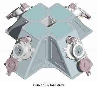
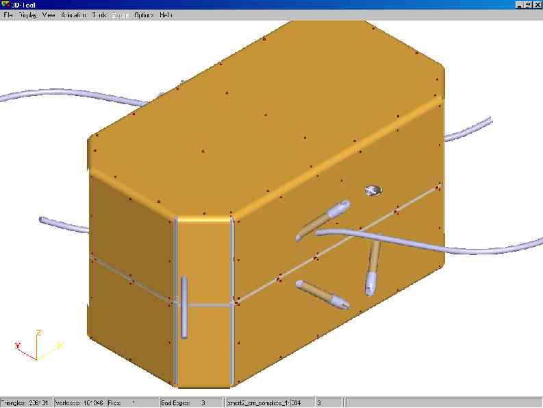
47 DRS Sensor Assembly


48 DRS Thrusters & Electronics Colloidal Thruster Assembly Electronics Assembly
49 LISA Pathfinder / SMART-2 The LISA Test-flight Package

50 The LTP architecture

51 The LISA Test-flight Package

52 The LTP EM

53 Vacuum enclosure Test-mass Electrode Housing Caging Mechanism Optical Window UV Optical Fibres for Discharging


54

55 The LTP Optical Bench

56 The LTP Optical Bench EM
57 Laser Metrology

58 Laser

59
60

61
62
63

64
65
66
67

68 LTP schedule (1)
69 LTP schedule (2)
70 Mission schedule J F M A M J J A S O N D J F M A M J J A S O N D J F M A M J J A S O N D J F M A M J J A S O N D J F M A M J J A S O N D J F M A M J J A S O N D MILESTONES SRR PDR HDR CDR FAR LRR IOCR FRR LAUNCH LTP EM AIVOB TB/TV & Performance Test LTP EM Delta Qual'n LTP EM Delivery IS EM Vibration test OMS LTP Ground Test LTP EM Integration LTP EM ASD LTP FM AIV OB Design Update Interferometer AIT LTP Integration & Test OB FM AIT LCA AIT LTP FM Delivery DRS FM AIV EID-A Interaction Project CDR EID-B Interaction DRS Integration & Test DRS FM Delivery Real Time bench SVF 1 Phase 1 EM LTP FM LTP Early and Late Deliveries E2E RTB Phase 1 E2E RTB Phase E2E RTB Phase 2 Integrate FM LTP to RTB 0422 E2E RTB Phase Spacecraft AIV Prop. Module Structure Mate Sci S/C and Prop'n Module Propulsion & Science Module Assembly & Test SPT-1 E2E Propulsion Module S/C Mass Properties Science Spacecraft FM LTP Electrical & Functional Tests Launch Composite Re-integrate Science Module to Propulsion Module SVT-2 Pack & Ship to Launch-site SVT-1 S/C Alignment & Mass Properties Launch Campaign Set-UP & Elect. IST Combined Operations Fuel S/C Launch
71 Key engineering milestones System specifications preparation => SRR (May 04) LTP & DRS EID-A/B finalisation => August 04 Subsystem specifications => ITT (June 04-March 05) Engineering Analyses through to PDR (May 05) Hardware Design Review to start RTB test (Oct 05) End of RTB test and design phase => CDR (Aug 06) LPT integration in FM (Sep 06) Electrical and Functional tests (Jan-Mar 07) Environmental Tests (Jun-Nov 07) Launch Campaign (Feb-Mar 08) Launch (Mar 08) In Orbit Commissioning Review (May 08)
LISA Pathfinder measuring pico-meters and femto-newtons in space
 LISA Pathfinder measuring pico-meters and femto-newtons in space M Hewitson for the LPF team Barcelona, February 15th 2012 Observing from Space 2 Observing from Space 2 Observing from Space Push down to
arxiv:gr-qc/ v1 15 Nov 2004
 Mission design for LISA Pathfinder arxiv:gr-qc/0411071v1 15 Nov 2004 M Landgraf, M Hechler, and S Kemble ESA/ESOC, Robert-Bosch-Straße 5, D-64293 Darmstadt, Germany E-mail: Markus.Landgraf@esa.int EADS
LISA Pathfinder Coldgas Thrusters
 LISA Pathfinder Coldgas Thrusters Joseph Martino/Eric Plagnol - LPF collaboration Lisa Symposium September 2016 Zurich Outline System Description External Disturbances and thruster noise In Flight dedicated
Plan for Compensation of Self-Gravity on ST-7/DRS
 Plan for Compensation of Self-Gravity on ST-7/DRS Jordan P. Evans Jet Propulsion Laboratory, California Institute of Technology Pasadena, CA 91109 Jordan.P.Evans@jpl.nasa.gov 5th International LISA Symposium
Thermal experiments in LISA Pathfinder: preparing for operations. Ferran Gibert
 Thermal experiments in LISA Pathfinder: preparing for operations Ferran Gibert 5th IGWM, Barcelona, May 13th 2015 LISA Pathfinder overview ESA mission with NASA collaboration to fly this year (!!!) Technology
The Quantum Sensor Challenge Designing a System for a Space Mission. Astrid Heske European Space Agency The Netherlands
 The Quantum Sensor Challenge Designing a System for a Space Mission Astrid Heske European Space Agency The Netherlands Rencontres de Moriond - Gravitation, La Thuile, 2017 Quantum Sensors in Lab Experiments
The Engineering of LISA Pathfinder the quietest Laboratory ever flown in Space
 Journal of Physics: Conference Series PAPER OPEN ACCESS The Engineering of LISA Pathfinder the quietest Laboratory ever flown in Space To cite this article: Christian Trenkel et al 2017 J. Phys.: Conf.
GG studies at TAS-I: state of the art
 GG studies at TAS-I: state of the art A. Anselmi INRIM, 24-10-2014 83230350-DOC-TAS-EN-002 GG@ThalesAleniaSpace! 1996 Early experiment concept presented to ESA HQ! Industrial support on satellite & drag-free
The Stanford Gravitational Reference Sensor
 The Stanford Gravitational Reference Sensor S. Buchman, B. Allard, G. Allen, R. Byer, W. Davis, D. DeBra, D. Gill, J. Hanson, G.M. Keiser, D. Lauben, I. Mukhar, N. A. Robertson, B. Shelef, K. Sun, S. Williams
Direct MOND/TEVES test with LISA Pathfinder
 Direct MOND/TEVES test with LISA Pathfinder Christian Trenkel and Steve Kemble Astrium Ltd, Stevenage, UK Joao Magueijo and Neil Bevis Imperial College, London, UK Fabrizio io demarchi and Giuseppe Congedo
Control of the Laser Interferometer Space Antenna
 Control of the Laser Interferometer Space Antenna P. G. Maghami, T. T. Hyde NASA Goddard Space Flight Center Guidance, Navigation and Control Division Greenbelt, MD 20771 J. Kim Swales Aerospace, Inc.
Gravitational & Planetary Research Program
 2012 Gravitational & Planetary Research Program Goals Why? Relativity, Gravitational Waves, Geodesy, Aeronomy Space Technology Education and Training: STEM Team Who? NASA Universities Industry Foreign
Observing the gravitational universe from space
 Observing the gravitational universe from space Peter Wass Tim Sumner, Daniel Hollington, Jonathon Baird High Energy Physics Group Imperial Space Lab 29 September 2015 Gravitational Waves Gravitational
In-flight thermal experiments for LISA Pathfinder
 , on behalf the LTPDA team Institut de Cie ncies de l Espai (ICE-CSIC/IEEC) Barcelona th LISA Symposium Gainesville, Florida, USA 1 Thermal Diagnostics in LISA Pathfinder Temperature noise in LISA Pathfinder
Introduction to LISA Pathfinder
 Introduction to LISA Pathfinder Prepared by Paul McNamara & Giuseppe Racca Reference LISA-LPF-RP-0002 Issue 1 Revision 1 Date of Issue 30 th March 2009 Contents 1 Introduction 2 2 LISA Pathfinder Science
Exploring the Gravitational Wave Universe Challenges for a LISA Successor
 Exploring the Gravitational Wave Universe Challenges for a LISA Successor H Ward University of Glasgow Cosmic Vision 2015 2025 Paris 15 th September 2004 With contributions from : P Bender, K Danzmann,
GP-B Attitude and Translation Control. John Mester Stanford University
 GP-B Attitude and Translation Control John Mester Stanford University 1 The GP-B Challenge Gyroscope (G) 10 7 times better than best 'modeled' inertial navigation gyros Telescope (T) 10 3 times better
From the first results of LISAPathfinder to LISA : First step to observing gravitational wave from space
 From the first results of LISAPathfinder to LISA : First step to observing gravitational wave from space Antoine Petiteau AstroParticule et Cosmologie Université Paris-Diderot Journée GPhys APC-Paris 6th
BepiColombo. Project and MPO Status. Comprehensive Explora1on of Planet Mercury
 BepiColombo Project and MPO Status Comprehensive Explora1on of Planet Mercury Joe Zender BepiColombo Deputy PS, ESA/ESTEC BepiColombo Previously: Ø Proba2 Science Coordinator, until 12/2013 Ø ProbaV, Project
Stanford, Space Gravity Research Group
 Stanford, Space Gravity Research Group John W. Conklin, Sasha Buchman, and Robert Byer Gravitational science Earth observation: Geodesy, aeronomy Gravity-waves 1 Space Gravity Technology Development Drag-free
Overview of the Jovian Exploration Technology Reference Studies
 Overview of the Jovian Exploration Technology Reference Studies The Challenge of Jovian System Exploration Peter Falkner & Alessandro Atzei Solar System Exploration Studies Section ESA/ESTEC Peter.Falkner@esa.int,
arxiv:gr-qc/ v2 16 Feb 2006
 Acceleration disturbances due to local gravity gradients in ASTROD I arxiv:gr-qc/0510045v2 16 Feb 2006 Sachie Shiomi Department of Physics, National Tsing Hua University, Hsinchu, Taiwan 30013 R.O.C. E-mail:
Alta FT-150: The Thruster for LISA Pathfinder and LISA/NGO Missions
 9 th LISA Symposium, Paris ASP Conference Series, Vol. 467 G. Auger, P. Binétruy and E. Plagnol, eds. c 2012 Astronomical Society of the Pacific Alta FT-150: The Thruster for LISA Pathfinder and LISA/NGO
Advancing the Utility of Small Satellites with the Development of a Hybrid Electric-Laser Propulsion (HELP) System
 System") Advancing the Utility of Small Satellites with the Development of a Hybrid Electric-Laser Propulsion (HELP) System Dr. Rachel Leach, Gerry Murphy & Tom Adams Design_Net Engineering LLC August 12, 2004
Advancing the Utility of Small Satellites with the Development of a Hybrid Electric-Laser Propulsion (HELP) System Dr. Rachel Leach, Gerry Murphy & Tom Adams Design_Net Engineering LLC August 12, 2004
IMPACT OF SPACE DEBRIS MITIGATION REQUIREMENTS ON THE MISSION DESIGN OF ESA SPACECRAFT
 IMPACT OF SPACE DEBRIS MITIGATION REQUIREMENTS ON THE MISSION DESIGN OF ESA SPACECRAFT Rüdiger Jehn (1), Florian Renk (1) (1 ) European Space Operations Centre, Robert-Bosch-Str. 5, 64293 Darmstadt, Germany,
ESA activities towards the Gravitation Waves Space Observatory
 ESA activities towards the Gravitation Waves Space Observatory Frédéric Safa ESA Science Directorate, Future Missions LISA Symposium, Zurich 2016 The Gravitation Wave Observatory in ESA Science Programme
Application Example: Quality Control
 Application Example: Quality Control Aerospace: Development of a Dimensionally Stable Lightweight Structure for the LISA Pathfinder Science Module Measuring Systems: TRITOP Keywords: thermo-elastic, climatic
Direct Thrust and Thrust Noise Measurements on the LISA Pathfinder Field Emission Thruster
 Direct Thrust and Thrust Noise Measurements on the LISA Pathfinder Field Emission Thruster IEPC-9-8 Presented at the st International Electric Propulsion Conference, University of Michigan Ann Arbor, Michigan
HYPER Industrial Feasibility Study
 HYPER Industrial Feasibility Study Executive Summary / Final Report Document Number HYP-9-04 Authors: Dr. Walter Fichter, Dr. Ulrich Johann Date: 25 June 2003 Astrium GmbH Page 2 Distribution List Name
DARE Mission and Spacecraft Overview
 DARE Mission and Spacecraft Overview October 6, 2010 Lisa Hardaway, PhD Mike Weiss, Scott Mitchell, Susan Borutzki, John Iacometti, Grant Helling The information contained herein is the private property
Make Your Cubesat Overnight and Put it in Any Orbit (Well almost)
") Make Your Cubesat Overnight and Put it in Any Orbit (Well almost) Jim White, Walter Holemans, Planetary Systems Inc. Dr. Adam Huang, University of Arkansas RAMPART Summary Main Components The Promise of
Make Your Cubesat Overnight and Put it in Any Orbit (Well almost) Jim White, Walter Holemans, Planetary Systems Inc. Dr. Adam Huang, University of Arkansas RAMPART Summary Main Components The Promise of
Catapult tests for microgravity characterization of the MICROSCOPE accelerometers. Manuel Rodrigues On behalf ONERA & ZARM team
 Catapult tests for microgravity characterization of the MICROSCOPE accelerometers Manuel Rodrigues mrodrig@onera.fr On behalf ONERA & ZARM team 1 Instrument Description SU sqm Sensor Unit (SU) = differential
EUROSTAR 3000 INCLINED ORBIT MISSION : LIFETIME OPTIMISATION IN CASE OF INJECTION WITH A LOW INCLINATION
 EUROSTAR 3000 INCLINED ORBIT MISSION : LIFETIME OPTIMISATION IN CASE OF INJECTION WITH A LOW INCLINATION Franck Raballand (1), Julie De Lamarzelle (2), François Bonaventure (3), Anne-Hélène Gicquel (4)
Attitude Determination and Control System Design for STU-2A Cubesat and In-Orbit Results
 13 th Annual Summer CubeSat Developer s Workshop August 6-7, 2016, Logan, Utah Attitude Determination and Control System Design for STU-2A Cubesat and In-Orbit Results Presented by Shufan Wu Guowen Sun,
INTERNAL THALES ALENIA SPACE
 Workshop Galileo Galilei (GG) and GGG lab prototype: state of the art and new possibilities Template reference : 100181670S-EN GG error budget from the end-to-end simulator developed at TAS-I Giuseppe
Microscope : A scientific Microsatellite development
 Microscope : A scientific Microsatellite development V. CIPOLLA, Y. ANDRE, P.Y. GUIDOTTI, A.ROBERT B. POUILLOUX, P. PRIEUR, L.PERRAUD Centre National d Etudes Spatiales 18 av. Edouard Belin Toulouse France
arxiv: v1 [gr-qc] 30 Jul 2012
![arxiv: v1 [gr-qc] 30 Jul 2012](/thumbs/80/81445468.jpg "arxiv: v1 [gr-qc] 30 Jul 2012") State-space modelling for heater induced thermal effects on LISA Pathfinder s Test Masses arxiv:127.6979v1 [gr-qc] 3 Jul 212 F Gibert 1,2, M Nofrarias 1,2, M Diaz-Aguiló 1,3, A Lobo 1,2, N Karnesis 1,2,
State-space modelling for heater induced thermal effects on LISA Pathfinder s Test Masses arxiv:127.6979v1 [gr-qc] 3 Jul 212 F Gibert 1,2, M Nofrarias 1,2, M Diaz-Aguiló 1,3, A Lobo 1,2, N Karnesis 1,2,
Orbit Design Marcelo Suárez. 6th Science Meeting; Seattle, WA, USA July 2010
 Orbit Design Marcelo Suárez Orbit Design Requirements The following Science Requirements provided drivers for Orbit Design: Global Coverage: the entire extent (100%) of the ice-free ocean surface to at
Astrophysics & Gravitational Physics with the LISA Mission
 Astrophysics & Gravitational Physics with the LISA Mission Peter L. Bender JILA, University of Colorado, and NIST Workshop on Robotic Science from the Moon Boulder, CO 5-6 October, 2010 LISA Overview The
HYPER Industrial Feasibility Study Final Presentation Orbit Selection
 Industrial Feasibility Study Final Presentation Orbit Selection Steve Kemble Astrium Ltd. 6 March 2003 Mission Analysis Lense Thiring effect and orbit requirements Orbital environment Gravity Atmospheric
Nanosat Science Instruments for Modular Gravitational Reference Sensor (MGRS)
") Microgravity White Paper Decadal Survey on Biological and Physical Sciences in Space Fundamental Physics Sciences (FPS) Applied Physical Sciences (APS) Nanosat Science Instruments for Modular Gravitational
Microgravity White Paper Decadal Survey on Biological and Physical Sciences in Space Fundamental Physics Sciences (FPS) Applied Physical Sciences (APS) Nanosat Science Instruments for Modular Gravitational
1
 Daniel.Schuetze@aei.mpg.de 1 Satellite gravimetry Mapping the global gravity field Static and dynamic components Many applications in geosciences Techniques Orbit determination and tracking Satellite-to-satellite
Optical Metrology Applications at TAS-I in support of Gravity and Fundamental Physics
 Optical Metrology Applications at TAS-I in support of Gravity and Fundamental Physics Template reference : 100181670S-EN Stefano Cesare, Thales Alenia Space Italia, Torino Workshop GG/GGG: state of the
Flight Demonstration of Electrostatic Thruster Under Micro-Gravity
 Flight Demonstration of Electrostatic Thruster Under Micro-Gravity Shin SATORI*, Hiroyuki MAE**, Hiroyuki OKAMOTO**, Ted Mitsuteru SUGIKI**, Yoshinori AOKI # and Atsushi NAGATA # * Hokkaido Institute of
Shally Saraf, Stanford University
 LAser GRavitational-wave ANtenna in GEocentric Orbit Shally Saraf, Stanford University for the LAGRANGE team Background LAser GRavitational-wave ANtenna in GEocentric Orbit was proposed originally as a
LISA mission design. Guido Mueller. APS April Meeting, Jan 30th, 2017, Washington DC
 LISA mission design Guido Mueller University of Florida APS April Meeting, Jan 30th, 2017, Washington DC 1 L3 from ESA s perspective 2013: Selection of L3 Science Theme by ESA The Gravitational Universe
RESERVE THALES ALENIA SPACE CHANGE RECORDS ISSUE DATE DESCRIPTION OF CHANGES AUTHOR
 ISSUE : 1 Page : 2/35 CHANGE RECORDS ISSUE DATE DESCRIPTION OF CHANGES AUTHOR 1 03/10/07 Initial issue (MTG-TAF-SA-RS-39) J. VIEILLOT 1 20/09/10 Updated version for kick off : L.OUCHET New reference (MTG-TAF-SA-SS-0039)
Exploring the Mysteries of the Cosmos on the MOST Microsatellite Mission
 Exploring the Mysteries of the Cosmos on the MOST Microsatellite Mission Dr. Simon Grocott Dr. Robert E Zee Dr. Jaymie Matthews Dynacon Inc UTIAS SFL UBC 13 August 2003 Outline MOST (Microvariability and
Low Cost Helicon Propulsion System for CubeSat future mission scenarios. T4i - University of Padova D.Pavarin
 Low Cost Helicon Propulsion System for CubeSat future mission scenarios T4i - University of Padova D.Pavarin Centro di Ateneo Studi e Attività Spaziali University of Padova Padova, Italy Technology for
2 Each satellite will have two test masses, each being the end mirror for an interferometer.
 Ground Testing for LISA Test Masses with a Torsion Pendulum Matthew Schmidt Valdosta State University International REU: University of Trento, Italy Advisor: Dr. Bill Weber Abstract: One of the most important
The Swarm Vector Field Magnetometer (VFM): instrument commissioning & performance assessment José M. G. Merayo
: instrument commissioning & performance assessment José M. G. Merayo") instrument commissioning & performance assessment José M. G. Merayo DTU Space, Technical University of Denmark Division Measurement & Instrumentation Systems overview Fluxgate principle Amorphous magnetic
instrument commissioning & performance assessment José M. G. Merayo DTU Space, Technical University of Denmark Division Measurement & Instrumentation Systems overview Fluxgate principle Amorphous magnetic
Precision Attitude and Translation Control Design and Optimization
 Precision Attitude and Translation Control Design and Optimization John Mester and Saps Buchman Hansen Experimental Physics Laboratory, Stanford University, Stanford, California, U.S.A. Abstract Future
Asteroid Impact Mission AIM Workshop. Electric Propulsion for Attitude & Orbit Control
 Asteroid Impact Mission AIM Workshop Electric Propulsion for Attitude & Orbit Control ESA, ESTEC, Noordwijk, The Netherlands, 22-23 February 2016 Christophe R. Koppel Consulting Ind., 75008 Paris, France
GOES-R Instrument Status and Accommodations. Barbara Pfarr GOES-R Program Systems Engineering January 2010 AMS Conference
 GOES-R Instrument Status and Accommodations Barbara Pfarr GOES-R Program Systems Engineering January 2010 AMS Conference Agenda Instrument Developmental Status Significant Changes in the Last Year Introducing
XENON RESISTOJETS AS SECONDARY PROPULSION ON EP SPACECRAFTS AND PERFORMANCE RESULTS OF RESISTOJETS USING XENON
 XENON RESISTOJETS AS SECONDARY PROPULSION ON EP SPACECRAFTS AND PERFORMANCE RESULTS OF RESISTOJETS USING XENON D. Nicolini (a), D. Robertson (a), E. Chesta (a), G. Saccoccia (a), D. Gibbon (b), A. Baker
LISA Technology: A Status Report
 LISA Technology: A Status Report Guido Mueller University of Florida Minnesota 2010 1 Content LISA Concept Gravitational Reference Sensor Interferometry Measurement System Status/Outlook 2 LISA Concept
Optimal Control based Time Optimal Low Thrust Orbit Raising
 Optimal Control based Time Optimal Low Thrust Orbit Raising Deepak Gaur 1, M. S. Prasad 2 1 M. Tech. (Avionics), Amity Institute of Space Science and Technology, Amity University, Noida, U.P., India 2
Pioneer anomaly: Implications for LISA?
 Pioneer anomaly: Implications for LISA? Denis Defrère Astrophysics and Geophysics Institute of Liege (Belgium) Andreas Rathke EADS Astrium GmbH Friedrichshafen (Germany) ISSI Meeting - Bern November 10th
PROBA 1. F. Teston ESA/ESTEC D/TEC-EL
 PROBA 1 F. Teston ESA/ESTEC D/TEC-EL Frederic.Teston@esa.int PROBA 1 launch PROBA 1 has been launched on 21 October 2001 Orbital parameters: Altitude: 681-561 km Near polar (inclination of 97.9 ) Sun-synchronous
Propulsion means for CubeSats
 Propulsion means for CubeSats C. Scharlemann and D. Krejci 2009 CubeSat Developers Workshop, San Louis Obispo, CA Welcome to the Austrian Research Centers Space Propulsion & Advanced Concepts Staff: 11
Drag-free Control and Drag Force Recovery of Small Satellites
 Drag-free Control and Drag Force Recovery of Small Satellites Anh N. Nguyen NASA Ames Research Center NASA Ames Research Center, M/S 202-3, Bldg N202, Moffett Field, CA 93035 anh.n.nguyen@nasa.gov John
Alta s FT-150 FEEP Microthruster: Development and Qualification Status
 Alta s FT-150 FEEP Microthruster: Development and Qualification Status IEPC-2009-186 Presented at the 31st International Electric Propulsion Conference, University of Michigan Ann Arbor, Michigan USA L.
The Integrated Structural Electrodynamic Propulsion (ISEP) Experiment
 Experiment") The Integrated Structural Electrodynamic Propulsion (ISEP) Experiment Nestor Voronka, Robert Hoyt, Tyrel Newton, Ian Barnes Brian Gilchrist (UMich( UMich), Keith Fuhrhop (UMich) TETHERS UNLIMITED, INC.
The Integrated Structural Electrodynamic Propulsion (ISEP) Experiment Nestor Voronka, Robert Hoyt, Tyrel Newton, Ian Barnes Brian Gilchrist (UMich( UMich), Keith Fuhrhop (UMich) TETHERS UNLIMITED, INC.
The Interstellar Boundary Explorer (IBEX) Mission Design: A Pegasus Class Mission to a High Energy Orbit
 Mission Design: A Pegasus Class Mission to a High Energy Orbit") The Interstellar Boundary Explorer (IBEX) Mission Design: A Pegasus Class Mission to a High Energy Orbit Ryan Tyler, D.J. McComas, Howard Runge, John Scherrer, Mark Tapley 1 IBEX Science Requirements IBEX
The Interstellar Boundary Explorer (IBEX) Mission Design: A Pegasus Class Mission to a High Energy Orbit Ryan Tyler, D.J. McComas, Howard Runge, John Scherrer, Mark Tapley 1 IBEX Science Requirements IBEX
BUILDING LOW-COST NANO-SATELLITES: THE IMPORTANCE OF A PROPER ENVIRONMENTAL TESTS CAMPAIGN. Jose Sergio Almeida INPE (Brazil)
") BUILDING LOW-COST NANO-SATELLITES: THE IMPORTANCE OF A PROPER ENVIRONMENTAL TESTS CAMPAIGN Jose Sergio Almeida INPE (Brazil) 1 st International Academy of Astronautics Latin American Symposium on Small
BUILDING LOW-COST NANO-SATELLITES: THE IMPORTANCE OF A PROPER ENVIRONMENTAL TESTS CAMPAIGN Jose Sergio Almeida INPE (Brazil) 1 st International Academy of Astronautics Latin American Symposium on Small
11.1 Survey of Spacecraft Propulsion Systems
 11.1 Survey of Spacecraft Propulsion Systems 11.1 Survey of Spacecraft Propulsion Systems In the progressing Space Age, spacecrafts such as satellites and space probes are the key to space exploration,
ESA UNCLASSIFIED For Official Use. BepiColombo à Exploring Mercury
 BepiColombo à Exploring Mercury ESA / JAXA BepiColombo Mercury Mercury has always been something of a puzzle for planetary scientists. Its close position to the Sun means it is very difficult to observe.
Figure 1. View of ALSAT-2A spacecraft
 ALSAT-2A TRANSFER AND FIRST YEAR OPERATIONS M. Kameche (1), A.H. Gicquel (2), D. Joalland (3) (1) CTS/ASAL, 1 Avenue de la Palestine, BP 13, Arzew 31200 Oran, Algérie, email:mo_kameche@netcourrier.com
Integral in Orbit* The Integral satellite was launched on 17 October 2002, at
 * The Integral satellite was launched on 17 October 2002, at 4:41 Universal Time, from Baikonur aboard a Proton rocket. The flawless launch marked the culmination of more than a decade of work for the
ESSE Payload Design. 1.2 Introduction to Space Missions
 ESSE4360 - Payload Design 1.2 Introduction to Space Missions Earth, Moon, Mars, and Beyond Department of Earth and Space Science and Engineering Room 255, Petrie Science and Engineering Building Tel: 416-736
SOLAR ROCKET PROPULSION Ground and Space Technology Demonstration. Dr. Michael Holmes, AFRL/PRSS
 SOLAR ROCKET PROPULSION Ground and Space Technology Demonstration Dr. Michael Holmes, AFRL/PRSS Solar Thermal Propulsion Concept Parabolic Mirror Sun Create thrust by collecting and focusing sunlight to
Technical Proposal: Self-Assembling Space Structures
 Excerpt For Public Release: Technical Proposal: 2018 Marcus van Bavel All rights Reserved Part 1: Table of Contents Part 1: Table of Contents... 1 Part 2: Significance of...1 Theory of Operation...3 Example
Recent Advances and Low cost concept for the Gamma-Ray Lens Project MAX
 . Page 1 Recent Advances and Low cost concept for the Gamma-Ray Lens Project MAX ---- F. Arbusti a, P. Attina b X. Leyre a, M. Sghedoni a a Alcatel Alenia Space - Cannes - France. b Alcatel Alenia Space
Formation Flying and Rendezvous and Docking Simulator for Exploration Missions (FAMOS-V2)
") Formation Flying and Rendezvous and Docking Simulator for Exploration Missions (FAMOS-V2) Galder Bengoa, F. Alonso, D. García, M. Graziano (GMV S.A.) Dr. Guillermo Ortega (ESA/ESTEC) 2nd ESA Workshop on
Formation Flying and Rendezvous and Docking Simulator for Exploration Missions (FAMOS-V2) Galder Bengoa, F. Alonso, D. García, M. Graziano (GMV S.A.) Dr. Guillermo Ortega (ESA/ESTEC) 2nd ESA Workshop on
BepiColombo Project Status. Presentation for MESSENGER Science Team Meeting Via-Skype, 27 th March 2015
 BepiColombo Project Status Johannes.Benkhoff@esa.int Presentation for MESSENGER Science Team Meeting Via-Skype, 27 th March 2015 Project status The purpose of this presentation is to give an overview on
Technology Readiness Level:
 Technology Readiness Level: We plan to raise the TRL of the model with an acceleration noise performance requirement of < 10-12 m sec -2 Hz -1/2 at frequencies between 1 mhz and 1 Hz, from TRL 3 to TRL
BepiColombo Mission to Mercury - コロンボ. October Jan van Casteren, Mauro Novara.
 ベピ - コロンボ BepiColombo Mission to Mercury October 2010 Jan van Casteren, Mauro Novara http://www.esa.int/science/bepicolombo June 2010 1 BepiColombo Scientific Objectives Origin and evolution of a planet
Mission Design Options for Solar-C Plan-A
 Solar-C Science Definition Meeting Nov. 18, 2008, ISAS Mission Design Options for Solar-C Plan-A Y. Kawakatsu (JAXA) M. Morimoto (JAXA) J. A. Atchison (Cornell U.) J. Kawaguchi (JAXA) 1 Introduction 2
Design of Attitude Determination and Control Subsystem
 Design of Attitude Determination and Control Subsystem 1) Control Modes and Requirements Control Modes: Control Modes Explanation 1 ) Spin-Up Mode - Acquisition of Stability through spin-up maneuver -
Preparation of the data analysis of the gravitational wave space antenna.
 Preparation of the data analysis of the gravitational wave space antenna. 1) LISA (Laser Interferometer Space Antenna) Why? 2)How? 1 Frequency Limitation Seismic noise cannot be cancelled at low-frequency
High Power Electric Propulsion Pointing Mechanisms (HP EPPM) Technical Development Activities (TDA s) strategy, status and planning
 Technical Development Activities (TDA s) strategy, status and planning") High Power Electric Propulsion Pointing Mechanisms (HP EPPM) Technical Development Activities (TDA s) strategy, status and planning Objectives of this presentation are: To provide primes with: ESA preliminary
High Power Electric Propulsion Pointing Mechanisms (HP EPPM) Technical Development Activities (TDA s) strategy, status and planning Objectives of this presentation are: To provide primes with: ESA preliminary
Cold Gas Thruster Qualification for FORMOSAT 5
 Cold Gas Thruster Qualification for FORMOSAT 5 By Hans-Peter HARMANN 1), Tammo ROMBACH 2) and Heiko DARTSCH 1) 1) AST Advanced Space Technologies GmbH, Stuhr, Germany 2) SpaceTech GmbH, Immenstaad, Germany
Space-based gravitational wave observatories
 elisa/ngo and LISA Pathfinder Max Planck Institute for Gravitational Physics Astroteilchenphysik-Tagung Zeuthen, 20.09.2012 Sources of gravitational waves Binary systems NS-NS, BH-BH, close WD Massive
The ACES Mission. Fundamental Physics Tests with Cold Atom Clocks in Space. L. Cacciapuoti European Space Agency
 The ACES Mission Fundamental Physics Tests with Cold Atom Clocks in Space L. Cacciapuoti European Space Agency La Thuile, 20-27 March 2011 Gravitational Waves and Experimental Gravity 1 ACES Mission Concept
JUICE: A European Mission to Jupiter and its Icy Moons. Claire Vallat Prague, 15 th November 2018
 JUICE: A European Mission to Jupiter and its Icy Moons Claire Vallat Prague, 15 th November 2018 Emergence of habitable worlds around the gas giants The Jupiter icy moons family portrait [Lammer et al,
1) Thermal Stability in the frequency domain. 2) THERMAL DESKTOP translation tools
 Thermal Stability in the frequency domain. 2) THERMAL DESKTOP translation tools") 1) Thermal Stability in the frequency domain 2) THERMAL DESKTOP translation tools Marco Molina and Christian Vettore Mechanical and Thermal Engineering Department mmolina@cgspace.it Carlo Gavazzi Space
1) Thermal Stability in the frequency domain 2) THERMAL DESKTOP translation tools Marco Molina and Christian Vettore Mechanical and Thermal Engineering Department mmolina@cgspace.it Carlo Gavazzi Space
New Worlds Observer Final Report Appendix J. Appendix J: Trajectory Design and Orbit Determination Lead Author: Karen Richon
 Appendix J: Trajectory Design and Orbit Determination Lead Author: Karen Richon The two NWO spacecraft will orbit about the libration point created by the Sun and Earth/Moon barycenter at the far side
Status of the Indium FEEP Micropropulsion Subsystem Development for LISA Pathfinder
 Status of the Indium FEEP Micropropulsion Subsystem Development for LISA Pathfinder IEPC-2007-122 C. Scharlemann 1, A. Genovese 2, N. Buldrini 3, R. Schnitzer 4, M. Tajmar 5 Austrian Research Centers GmbH-ARC,
A DETAILED IMPACT RISK ASSESSMENT OF POSSIBLE PROTECTION ENHANCEMENTS TO TWO LEO SPACECRAFT
 A DETAILED IMPACT RISK ASSESSMENT OF POSSIBLE PROTECTION ENHANCEMENTS TO TWO LEO SPACECRAFT H. Stokes (1), C. Cougnet (2), M. David (3), J. Gelhaus (4), M. Röthlingshöfer (5) (1) PHS Space Ltd, 8 Dixon
The Orbit Control of ERS-1 and ERS-2 for a Very Accurate Tandem Configuration
 The Orbit Control of ERS-1 and ERS-2 for a Very Accurate Tandem Configuration Mats Rosengren European Space Operations Centre Robert Bosch Str 5 D64293 Darmstadt Germany Email: mrosengr@esoc.esa.de Abstract
Team X Study Summary for ASMCS Theia. Jet Propulsion Laboratory, California Institute of Technology. with contributions from the Theia Team
 Team X Study Summary for ASMCS Theia Jet Propulsion Laboratory, California Institute of Technology with contributions from the Theia Team P. Douglas Lisman, NASA Jet Propulsion Laboratory David Spergel,
End of Life Re-orbiting The Meteosat-5 Experience
 End of Life Re-orbiting The Meteosat-5 Experience Milan EUMETSAT, Darmstadt, Germany This article illustrates the orbit maneuver sequence performed during Meteosat- 5 End of Life (EOL) re-orbiting operations
Herschel Mission Overview and Key Programmes
 Herschel Mission Overview and Key Programmes SPIE Astronomical Instrumentation 2008 Space Telescopes and Instrumentation I: Optical, Infrared, and Millimeter Wave Marseille, 23-28 June 2008 Göran L. Pilbratt
SOLAR ORBITER Linking the Sun and Inner Heliosphere. Daniel Müller
 SOLAR ORBITER Linking the Sun and Inner Heliosphere Outline Science goals of Solar Orbiter Focus of HELEX joint mission Mission requirements Science payload Status update Top level scientific goals of
Your Partner in Environment Monitoring
 Your Partner in Environment Monitoring Radiation Environment in Space The ionizing radiation in space represents one of the most severe environmental loads to space hardware and can cause a large number
Mechanical and Thermal Design of XMM
 r bulletin 100 december 1999 Mechanical and Thermal Design of XMM K. van Katwijk, T. van der Laan & D. Stramaccioni XMM Project, ESA Directorate for Scientific Programmes, ESTEC, Noordwijk, The Netherlands
mstar: Space-Time Asymmetry Research
 mstar: Space-Time Asymmetry Research Testing Lorentz Invariance in Low-Earth Orbit Abdulaziz Alhussien for the mstar team November 15 th, 2013 1 Kinematic Approach to LIV Is the CMB a preferred frame?
A Low-Cost Mission for LISA Markus Landgraf, Florian Renk, Pierre Joachim, Rüdiger Jehn HSO-GFA
 A Low-Cost Mission for LISA Markus Landgraf, Florian Renk, Pierre Joachim, Rüdiger Jehn HSO-GFA LISA Internal Final Presentation July 8 th, 2011 CDF HSO-GFA Page 1 Overview Basic working assumptions Operational
CAS-ESA Call for small mission proposals - Technical annex
 CAS-ESA Call for small mission proposals - Technical annex Copenhagen workshop 23/09/2014 Table of contents 1. General considerations Mass & power Schedule Work breakdown and share Technology readiness
Study Participants: T.E. Sarris, E.R. Talaat, A. Papayannis, P. Dietrich, M. Daly, X. Chu, J. Penson, A. Vouldis, V. Antakis, G.
 GLEME: GLOBAL LIDAR EXPLORATION OF THE MESOSPHERE Project Technical Officer: E. Armandillo Study Participants: T.E. Sarris, E.R. Talaat, A. Papayannis, P. Dietrich, M. Daly, X. Chu, J. Penson, A. Vouldis,