Conjugate Heat Transfer On A Gas Turbine Blade
|
|
|
- Darleen Morgan
- 6 years ago
- Views:
Transcription
.")

1 University of Central Florida Electronic Theses and Dissertations Masters Thesis (Open Access) Conjugate Heat Transfer On A Gas Turbine Blade 2010 Santiago Salazar University of Central Florida Find similar works at: University of Central Florida Libraries Part of the Engineering Commons STARS Citation Salazar, Santiago, "Conjugate Heat Transfer On A Gas Turbine Blade" (2010). Electronic Theses and Dissertations This Masters Thesis (Open Access) is brought to you for free and open access by STARS. It has been accepted for inclusion in Electronic Theses and Dissertations by an authorized administrator of STARS. For more information, please contact lee.dotson@ucf.edu.
2 CONJUGATE HEAT TRANSFER ON A GAS TURBINE BLADE by SANTIAGO SALAZAR B.S. University of Central Florida, 2005 A thesis submitted in partial fulfillment of the requirements for the degree of Master of Science in the Department of Mechanical, Materials and Aerospace Engineering in the College of Engineering and Computer Science at the University of Central Florida Orlando, Florida Fall Term 2010
3 2010 Santiago Salazar ii
4 ABSTRACT Clearances between gas turbine casings and rotating blades is of quite importance on turbo machines since a significant loss of efficiency can occur if the clearances are not predicted accordingly. The radial thermal growths of the blade may be over or under predicted if poor assumptions are made on calculating the metal temperatures of the surfaces exposed to the fluid. The external surface of the blade is exposed to hot gas temperatures and it is internally cooled with air coming from the compressor. This cold air enters the radial channels at the root of the blade and then exists at the tip. To obtain close to realistic metal temperatures on the blade, the Conjugate Heat Transfer (CHT) approach would be utilized in this research. The radial thermal growth of the blade would be then compared to the initial guess. This work focuses on the interaction between the external boundary conditions obtained from the commercial Computational Fluid Dynamics software package CFX, the internal boundary conditions along the channels from a 1D flow solver proprietary to Siemens Energy, and the 3D metal temperatures and deformation of the blade predicted using the commercial Solid Mechanics software package ANSYS. An iterative technique to solve CHT problems is demonstrated and discussed. The results of this work help to highlight the importance of CHT in predicting metal temperatures and the implications it has in other aspect of the gas turbine design such as the tip clearances. iii
5 Dedicated to my Wife, Daughter, Dad, And Mom iv
6 ACKNOWLEDGMENTS I would like to thank first of all my advisor, Dr. Divo, for his support during my academic years. His ability to explain complex engineering problems in simple and accurate terms has been quite encouraging and very helpful. I consider myself lucky for having such great professors and in particular I would like to extend my gratitude to Dr. Alain Kassab for his continuous support and advice. Working and going to school was always enjoyable and for that I would like to thank my mentor at work, Andreas Hadjinicolaou, and my direct manager, Bob Dorris, for his understanding, and constant support. I wish to thank my family and extended family for their unconditional support, encouragement and for always creating such a lovely environment around me. Finally, I would like to thank my dear wife and daughter, for their unconditional love, patience and support. v
7 TABLE OF CONTENTS LIST OF FIGURES... vii LIST OF ABBREVIATIONS... ix CHAPTER ONE: MOTIVATION AND HYPOTHESIS... 1 CHAPTER TWO: LITERATURE REVIEW AND BACKGROUND... 2 CHAPTER THREE: RESEARCH METHODS Iterative Looping: Cooling Boundary Conditions: K1D Computational Fluid Dynamics Solver: CFX Thermo-Elastic Solver: ANSYS CHAPTER FOUR: RESULTS AND DISCUSSIONS Conjugate Convergence D Cooling Network Solution Volumetric CFD Solution Thermo-Elastic Mesh Solution CHAPTER FIVE: CONCLUSION LIST OF REFERENCES vi
8 LIST OF FIGURES Figure 1: SGT6-3000E Gas Turbine 60 Hertz Application... 5 Figure 2: Blade Figure 3: Blade 2 Tip... 6 Figure 4: Radial channels for cooling... 6 Figure 5: External loop... 7 Figure 6: Internal loop... 8 Figure 7: Blade geometry information in inches (a) cooling holes at blade inlet (b) cooling holes at airfoil section (c) radial dimensions Figure 8: Internal Flow model and boundary conditions Figure 9: Inlet conditions (a) Total Temperature (K) (b) Total Pressure (Pa) Figure 10: Outlet conditions (a) Total Temperature (K) (b) Static Pressure (Pa) Figure 11: Computational grid (a) end walls (b) domain periodicity (c) domain boundaries Figure 12: Solid 87 geometry Figure 13: Solid92 geometry Figure 14: SURF152 geometry Figure 15: SURF154 geometry Figure 16: FEA mesh (a) tip close up (b) blade Figure 17: Blade constraints (a) radial and circumferential (b) axial Figure 18: Turbulence model convergence Figure 19: L2 norm vii
9 Figure 20: Gap clearance at blade tip Figure 21: Internal results for first and last iterations (a) bulk temperature (b) heat transfer coefficients Figure 22: First and last iteration, (a) pressure (b) temperature (c) mach number Figure 23: First and last iterations, pressure contours, (a) suction side (b) pressure side 31 Figure 24: First and last Iteration, (a) airfoil heat transfer coefficient ( mw 2 mm K ) (b) airfoil bulk temperature ( o C) Figure 25: First and last iteration, (a) tip heat transfer coefficient ( mw 2 mm K ) (b) tip bulk temperature ( o C) Figure 26: Material properties IN738LC (a) density (b) specific heat (c) Poisson s ratio (d) thermal conductivity (e) mean coefficient of thermal expansion Figure 27: First and last iteration, channels metal temperatures ( o C) Figure 28: First and last iteration metal temperatures ( o C) (a) airfoil suction side (b) airfoil pressure side Figure 29: Von Misses stresses (MPa) (a) airfoil suction side (b) airfoil pressure side Figure 30: Blade displacements (mm) (a) z direction (b) y direction (c) x direction Figure 31: Nodal displacement at blade tip Figure 32: Nodal temperature at blade tip viii
10 LIST OF ABBREVIATIONS d: Diameter of channels, m h: Heat Transfer coefficient, or convection conductance, W/m 2.k L: Length, mm m: Mass, kg Nu: Pr: Nusselt number, h. d / k Prandlt Number, ν / α q : Heat flux, heat transfer rate at surface per unit area, W/m 2 Q: Mass transfer rate, kg/s r: Radius of channels, mm Re: S t : T s : T m : T bulk Reynolds Number, ρ V d / μ Stanton number, h / Gc Fluid temperature at the surface, K Metal temperature at the surface, K Fluid bulk temperature, K u: Mean velocity, m/s u : Assigned velocity at any desired point, m/s V: Axial velocity vector,v, m/s V: Velocity magnitude, m/s α: Thermal diffusivity, k / ρ. c p, m 2 /s ρ: Fluid density, kg/m 3 μ: Dynamic viscosity, N s / m 2 ix
11 ν: Kinematic viscosity, μ / ρ, m x
12 CHAPTER ONE: MOTIVATION AND HYPOTHESIS Standard practices to solve heat transfer problems on gas turbine components may not be adequately predicting metal temperatures. One factor for this to take place is the enormous amount of time that takes to set up a sufficient mesh that can be capable of producing reliable solutions when simultaneously solving the Navier-Stokes equations for the flow and the conduction for the solid. Another factor worth to be mentioned is the tedious labor involved in putting results files in formats that can be read by the solvers implicated in the calculations. In addition to the above interpolation techniques have to be used simultaneously in order to share information accurately between the conduction solver mesh and the flow solver mesh. So, when dealing with 3-D CHT problems, typically it is standard practice for each flow domain to be treated and solve independently and solutions never couple or fed back to the others solvers proficiently to form an efficient loop that can be capable of generating results close to actual experience. When failing to deal properly with a full 3D CHT problem such as the ones presented in most of the internally cooled gas turbine components metal temperatures are predicted incorrectly by several degrees, a debit is paid on calculating the life of the part, blade tip clearances may be over or under predicted, and the overall gas turbine efficiency might be compromised. 1
13 CHAPTER TWO: LITERATURE REVIEW AND BACKGROUND Gas turbines are rotary engines mainly used for aircraft propulsion and in land-based power generation. As main components, a simple cycle gas turbine has the compressor, combustor and turbine. The compressor that is located up stream of the turbine compresses the air increasing its pressure and temperature. Fuel is then mixed with air in the combustion section and ignited. This combustion produces a tremendous increase in energy where velocity, temperature and pressures of the working fluid are radically increased. This high energy fluid is directed through the stationary vanes over turbine blades and produces a rotational movement or spinning of the shaft that simultaneously assist to power the compressor. The shaft power output of the turbine depends on how much energy is extracted when expanding the hot gases passing through its vanes and blades and how successful this expansion is in reducing its exhaust temperature. The shaft power is then used among many other effects to power a generator for the production of the increasingly needed electric power. This increasing need over the past couple of decades has motivated the call for creative ways to increase efficiency and power out put. Typically, efficiency and power out put are increased with turbine inlet temperatures. These temperatures are normally above material melting point of the parts and it is because of these high temperatures that sophisticated cooling schemes are extremely important. Along, with these sophisticated cooling schemes, thermal barrier coatings 2
14 have as well been developed in the recent decades and are commonly used with internal cooled parts to increase part life. As mentioned above, modern gas turbine blade components are equipped with internal cooling features in order to withstand the high gas temperature at which they have to operate. The internal cooling is design to extract the heat from the internal walls and cool it significantly to maximize the life of the component. These cooling features in the turbine components affect part life and efficiency. So having ways to predict accurate metal temperatures is crucial. Too much cooling and the engine will pay a price on efficiency. Not enough cooling and the part life decreases and gets compromised. Furthermore, this extreme working environment produces intense stresses due to the high rotating speeds and thermal gradients. In addition, in order to achieve or increase efficiency the tip clearance between the gas turbine casing and the tip of the blade have to be maintained as minimum as possible and therefore play a very important roll on gas turbines power out put. In order to predict a more realistic radial thermal growth and/or tip clearance of the blade, conjugate heat transfer effects on internally cooled turbine components have to be taking into account. The interaction at the intersection between different domains in particular one of a moving fluid and solid is said to be set for a conjugate heat transfer problem as is the case for most modern gas turbine components. The temperatures solution at this intersection is coupled in a way that the energy and conduction equations of the fluid and solid respectively have to be solved in an iterative way. Once the metal temperatures at 3
15 these different domain intersections are found iteratively the radial growth of the blade could be predicted more realistically and life of the part can be predicted with confidence. CHT problems have been studied intensively in the past couple of decades and now with the use of sophisticated software packages and powerful computers more difficult and complex problems are solve faster and more accurately. This work focuses on the interaction between the external boundary conditions obtained from the commercial Computational Fluid Dynamics software package CFX, the internal boundary conditions along the channels from a 1D flow solver proprietary to Siemens Energy, and the 3D metal temperatures and deformation of the blade predicted using the commercial Solid Mechanics software package ANSYS. The blade used in this work belongs to the SGT6-3000E class engine (figure 1). It features a 19-stage axial flow compressor, 14 can-type combustor in a circular array and a four-stage turbine. It has a gross power output of 121MW and a gross efficiency of 34.7%. 4


16 Figure 1: SGT6-3000E Gas Turbine 60 Hertz Application The Pro-E model of the second stage blade used for this work is shown in figure 2. Figure 3 shows the tip of the blade which has a shroud design with the purpose of minimizing the hot air going over and circumventing the blade tip. Figure 2: Blade 2 5

.")
17 Figure 3: Blade 2 Tip The fluid used to cool the part is air coming from the earliest stages of the compressor. The blade has fifteen radial channels dedicated for internal cooling (see figure 4). They have their inlet at the root of the blade and exit at tip of the blade. Figure 4: Radial channels for cooling 6

18 CHAPTER THREE: RESEARCH METHODS 3.1 Iterative Looping: The approached taken to obtained the external boundary conditions for the 3D CHT problem is shown in figure 5. The external flow field inlet and outlet conditions are specified and an adiabatic wall assumption is made at the blade airfoil wall. The compressible Navier-Stokes (NS) equation is then solved for the external fluid region and a temperature profile is obtained for the airfoil. Assumptions for metal temperatures are made, the compressible NS are then solved again and then heat transfer coefficients and bulk temperature obtained. Figure 5: External loop 7

19 The approached taken to obtained the internal boundary conditions for the problem are shown in figure 6. Internally, supplied inlet, exit pressures and temperatures are specified and internal channel walls temperatures guessed. With this inputs the 1D compressible NS are solved and in effect gives the fluid bulk temperature and the heat transfer coefficient in the channel. These bulk temperature and heat transfer coefficients that were obtained for the internal and external fluid are fed as inputs to the conduction model in ANSYS. Once these boundary conditions are imposed to the model the metal temperatures distributions for the stage two rotating blade is obtained. The metal temperatures obtained from the conduction model are then used as inputs for the 3D and 1D fluid models and the process is repeated until the new metal temperatures found converge. In addition, at the end of each loop, the resultant metal temperatures distribution along with load pressures and centrifugal forces are used for the thermo-elasticity assessment and the blade growth monitored. Figure 6: Internal loop 8
20 3.2 Cooling Boundary Conditions: K1D Cooling holes dimensions and geometry used to build the internal cooling channels are shown in figure 7. (a) (b) 9
21 (c) Figure 7: Blade geometry information in inches (a) cooling holes at blade inlet (b) cooling holes at airfoil section (c) radial dimensions P=3 bars Channel walls initial guess T = 650 K P=9 bars, T=650 K Figure 8: Internal Flow model and boundary conditions 10
22 The geometrical information is used to build the internal flow network in the 1D flow solver where the channels are treated as smooth ducts with turbulent flow and entrance effects on overall heat transfer. Supplied inlet and exit pressures are specified along with inlet and wall temperatures of the channels. The inlet and exit pressures used for the internal cooling were 9 and 3 bars respectively. The inlet temperature and the initial temperature for the wall channel used was 650 K. Air properties in the channel are calculated taking into account area variations, wall friction, rotation and heat transfer. The internal flow network is shown in figure 8. The flow traveling radially upward through the channel sees its density change from inlet to outlet due to the heat pick up from the walls. For a heated channel the outlet density is smaller than inlet density < in and for the sections of constant channel areas the inlet velocities is less that the outlet velocity V. Continuity is maintained through the channel such that m VA at in V out every point in the channel On the contrary momentum m m G (1) A V out V in needs to be balanced due to the velocity differences at the channel s inlet and outlet by the pressure difference out P acc G 2 1 out 1 in (2) Empirical correlations are used to account for the pressure loss due to wall friction and adding this effect the pressure drop across a straight portion of the channel the pressure drop for the constant channel section takes the form 11
23 P s f 4L 1 V D 2 h 2 P acc (3) Where f is the friction factor, Dh is hydraulic diameter and is the average of the inlet and outlet densities. Contractions effects are taking into account as well and for air contracting from a large area A to a smaller area A this can be put in the form a b P V K V a Pb 1 a b b b c b b 2 2 (4) Where a b is the passage contraction ratio a b A A b a (5) And is the contraction loss coefficient. K c In the same manner expansion effects from a small area A to a large area A in the channel can be put in the following equation c d P d V K V Pc 1 c d c c e c c 2 2 (6) Where Ke is the enlargement loss coefficient and c d is given by c d A A c d (7) The effects of heat addition in the channel are measured by empirical correlations of the Stanton number S t. The Stanton number is a dimensionless number that relates the ratio of the heat transfer coefficient to the thermal capacity of the fluid C p 12
24 h St C p V (8) This relation can also be used in conjunction with the Nusselt number Nu, the Reynolds number Re and the Prandtl number Pr Nu St RePr (9) 3.3 Computational Fluid Dynamics Solver: CFX Figure 9 and 10 shows the inlet and outlet boundary conditions profiles for the flow domain as a function of radial position. The maximum total pressure and temperature at the inlet are 716,000 Pa and 1250 K respectively. At the outlet the maximum static pressure and temperature are 380,000 Pa and 1,250 K respectively. 13
25 (a) (b) Figure 9: Inlet conditions (a) Total Temperature (K) (b) Total Pressure (Pa) 14
26 (a) (b) Figure 10: Outlet conditions (a) Total Temperature (K) (b) Static Pressure (Pa) 15


27 The domain and domain boundary conditions of the main flow are shown in figure 11. The basic dimensions of the flow domain are 69 mm in width, 187 mm in length and, 190 mm of height at the inlet and 243 mm of height at the exit. The structured mesh uses 454,145 number of nodes, 435,456 number of elements, 435,456 total number of hexahedrons, and 77472total number of faces. (a) (b) 16

28 Wall Interface Outlet Inlet Wall (c) Figure 11: Computational grid (a) end walls (b) domain periodicity (c) domain boundaries The motion and heat transfer of the fluid in the flow-field are described by the compressible NS equations and can be expressed in the form of continuity, momentum and energy equations. The continuity equation can be expressed as t V 0 (10) The momentum equation describing the force balances of the fluid can be expressed as t V VV p (11) 17
29 Where, is the stress tensor. Based on the first law of thermodynamics the energy equation can be put in the following form Where h t tot is the total enthalpy h tot p t uh k T u (12) tot h tot 1 h V V 2 (13) And k is the thermal conductivity The solution of the Navier-Stokes equations for non ideal flows is obtained by applying the finite volume methodology. This method evaluates the continuity, momentum and energy equations as algebraic approximations and then solves them by applying numerical methods. Turbulence in the flow field is dealt by the use of the Eddy Viscosity Turbulence Models. Under this category the Two Equation Turbulent Model is used since they offer a good compromise between numerical effort and computational accuracy. The Two Equation Turbulence Model used for this simulation was the Shear Stress Transport (SST). The k w based SST model is known to accurately predict the amount of flow separation under adverse pressure gradients. 18
30 3.4 Thermo-Elastic Solver: ANSYS The blade material used for thermo-elastic analysis was a nickel-base alloy IN738LC. figure 16 shows the mesh used in Ansys. Solid element 87 was used for the thermal solution, along with surface effect elements 152. The structural analysis uses the same mesh as the thermal analysis and it was solved using solid element 92 and surface 154. Solid87 is a 3-D 10-node tetrahedral thermal solid particularly used to model irregular meshes. Element Solid 87 possesses one degree of freedom, temperature, at each node. Figure 12 shows the geometry of element Solid 87, nodes location and coordinate system. Figure 12: Solid 87 geometry When the same model containing Solide87 is also to be analyzed structurally is typically replaced by a 10-node tetrahedral structural solid element, Solid 92. This element has three degrees of freedom at each node: translations in the nodal x, y, and z directions. Figure 13 shows the element geometry. 19


31 Figure 13: Solid92 geometry SURF152 is a surface effect element overlaid onto the area face of any 3-D thermal element and the geometry, nodes and coordinate system are shown in figure 14. Figure 14: SURF152 geometry SURF154 is a surface effect element overlaid onto the area face of any 3-D structural element and the geometry, nodes and coordinate system are shown in figure

32 Figure 15: SURF154 geometry The blade geometry was poorly constructed on some critical areas as the blade root serrations, and the blade tip. More over in order to effectively mesh the cooling hole channels and to refine the areas mention above more elements had to be added to refine the mesh. The total number of elements used was 673,425 and the total number of nodes 866,637. (a) 21

33 (b) Figure 16: FEA mesh (a) tip close up (b) blade 2 The internal and external heat transfer coefficients and bulk temperatures imposed on the blade to assess the metal temperatures were taken from the 1D and CFX solutions respectively. A metal temperature of 400 o C was used for the blade root along with an h of 0.5 mw mm 2 K The governing equation for the conduction problem is k T s T 0 s Where T s represents the blade surface temperatures and k is a function of the metal temperature. After solving for the metal temperatures a structural analysis is perform using the thermal solutions as body loads. The blade was constraint at the root serrations circumferentially 22
. This method discretizes the domain into sub-domains called elements.")
34 and radially and it was constraint axially at the aft bottom hook as shown in figure 13. More over, the effect of the blade rotation was modeled by indicating an angular velocity on the z axis. The technique to solve the thermo-elasticity problem is known as Finite element Analysis (FEA). This method discretizes the domain into sub-domains called elements. Assumes a function that describes the behavior of the element, assembles the elements properties to obtain the system equations, imposes boundary conditions and solve the system equations. (a) 23
 axial")
35 (b) Figure 17: Blade constraints (a) radial and circumferential (b) axial 24

36 CHAPTER FOUR: RESULTS AND DISCUSSIONS 4.1 Conjugate Convergence It takes over 128 iterations to solve the equations in the flow domain and it takes approximately 5,729 seconds of CPU time to achieve convergence criteria. A snap shot in time of the turbulence model convergence is shown in figure 14. Figure 18: Turbulence model convergence 25
37 The conduction model takes 4,980 seconds of CPU time to converge while the convergence time from the 1D solver is negligible compared to the flow and conduction models. The L2 norms of the five thermal loops are shown in figure 19. The metal temperatures become stable after fifth iteration. Figure 19: L2 norm The average tip clearance of the blade is 4.11 mm. Figure 20 shows the radial growth of the blade after every thermal loop. The radial displacements are steady after the third iteration and compared to the first iteration the growth is under predicted by mm. 26
38 1 Blade Tip Gap Gap (mm) N iteration Figure 20: Gap clearance at blade tip 4.2 1D Cooling Network Solution The airfoil channels bulk temperature and heat transfer coefficient results for the first and last iteration are shown in figure 21. The average heat pick up is approximately 200 K and the average heat transfer coefficient is approximately 2,700 W m 2 K (a) 27
39 (b) Figure 21: Internal results for first and last iterations (a) bulk temperature (b) heat transfer coefficients 4.3 Volumetric CFD Solution Figure 22 shows the fluid pressure, temperature and mach number results from CFX solution. High pressure regions are seen at the stagnation point and in the airfoil pressure side; the airfoil suction side shows the lower pressures as expected. Unlike the pressure distribution the mach numbers on the fluid domain are low on the pressure side and high on the suction side of the blade. The results also show that the fluid total temperature for the first loop is higher near the airfoil walls than the last loop. Figure 23 shows the pressure contours on the blade airfoil that will be used as boundary conditions for the thermo-elasticity problem. The maximum pressure seen is approximately 5.6 MPa and is located on the airfoil pressure side. Figures 24 through 25 show the gas heat transfer coefficients and the bulk temperature at the airfoil, and tip of the blade. 28


40 (a) (b) 29

 mach")
41 (c) Figure 22: First and last iteration, (a) pressure (b) temperature (c) mach number 30


 suction")
42 (a) (b) Figure 23: First and last iterations, pressure contours, (a) suction side (b) pressure side 31
43 (a) (b) Figure 24: First and last Iteration, (a) airfoil heat transfer coefficient ( mw 2 mm K ) (b) airfoil bulk temperature ( o C) 32
 tip heat")
 (b) tip bulk temperature (")
44 (a) (b) Figure 25: First and last iteration, (a) tip heat transfer coefficient ( mw 2 mm K ) (b) tip bulk temperature ( o C) 33
45 4.4 Thermo-Elastic Mesh Solution The material used for the conduction problem is a nickel-base alloy IN738LC. The material properties as a function of temperature are listed in figure Density [kg/dm 3 ] Temperature [ o C] (a) 34
46 Specific Heat [J/kg-K] Temperature [ o C] (b) Poisson's Ratio Temperature [ o C] (C) 35
47 Thermal Conductivity [W/m-K] Temperature [ o C] (d) Mean Coeff of Linear Therm. Exp. [10-6 /K] Temperature [ o C] (e) Figure 26: Material properties IN738LC (a) density (b) specific heat (c) Poisson s ratio (d) thermal conductivity (e) mean coefficient of thermal expansion 36


48 The surface metal temperatures distributions along the channels are shown in figure 27. The channel close to the trailing of the airfoil experiences the hottest temperature of o C while the channels at the root of the blade are maintain considerably cooled at o C. The maximum temperature on the last iteration is approximately 113 o C higher than the first iteration. Figure 27: First and last iteration, channels metal temperatures ( o C) 37

49 (a) (b) Figure 28: First and last iteration metal temperatures ( o C) (a) airfoil suction side (b) airfoil pressure side As shown in figure 28 the hottest areas on the blade are the leading edge and trailing edge being the trailing edge the area of maximum temperature with o C. Figure 28 also shows how the contours of higher temperature are more intense on the last iteration than the first one. 38


50 The Von Misses stresses are shown in figure 29 and figure 30 shows the blade growth in the x, y, and z directions for the first and last iteration. The maximum displacement obtained in the last iteration in the radial direction is 3.36 mm, mm greater than the one obtained in the first iteration. (a) (b) Figure 29: Von Misses stresses (MPa) (a) airfoil suction side (b) airfoil pressure side 39

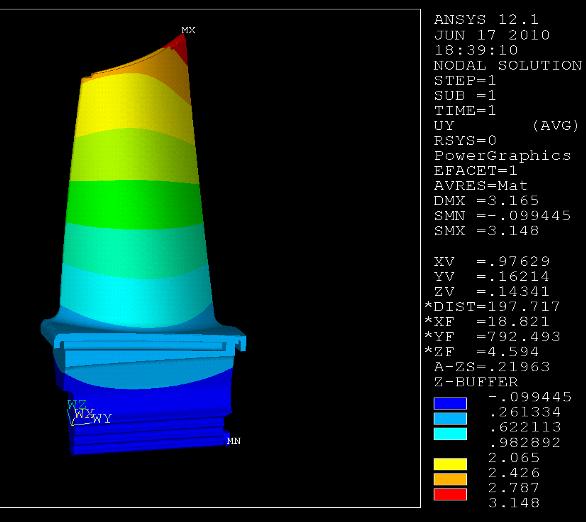
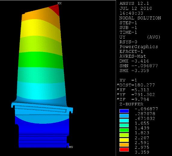
51 (a) (b) 40


52 (c) Figure 30: Blade displacements (mm) (a) z direction (b) y direction (c) x direction For comparison purposes some nodes from the tip of the blade were selected and their displacements in the radial directions and temperatures are shown in figure 31 and figure 32 respectively. Node number 1 is at the leading edge tip of the blade and node number 14 is at the trailing edge tip of the blade. 41
53 Radial Displacement [mm] First Iteration Last Iteration Nodes at Blade Tip Figure 31: Nodal displacement at blade tip Temepratures [ o C] First Iteration Last Iteration Nodes at Blade Tip Figure 32: Nodal temperature at blade tip 42
54 CHAPTER FIVE: CONCLUSION Clearances between gas turbine casings and rotating blades is of quite importance on turbo machines since a significant loss of efficiency can occur if the clearances are not predicted accordingly. The radial thermal growths of the blade may be over or under predicted if poor assumptions are made on calculating the metal temperatures of the surfaces exposed to the fluid. The external surface of the blade is exposed to hot gas temperatures and it is internally cooled with air coming from the compressor. This cold air enters the radial channels at the root of the blade and then exists at the tip. To obtain close to realistic metal temperatures on the blade, the Conjugate Heat Transfer (CHT) approach was utilized in this research. The radial thermal growth of the blade was then compared to the initial guess. This work focused on the interaction between the external boundary conditions obtained from the commercial Computational Fluid Dynamics software package CFX, the internal boundary conditions along the channels from a 1D flow solver proprietary to Siemens Energy, and the 3D metal temperatures and deformation of the blade predicted using the commercial Solid Mechanics software package ANSYS. An iterative technique to solve CHT problems was demonstrated and discussed. The results of this work helped to highlight the importance of CHT in predicting metal temperatures and the implications it has in other aspect of the gas turbine design such as the tip clearances. 43
55 LIST OF REFERENCES [1] Abram S. Dorfman, "Conjugate Problems In Convective Heat Transfer," CRC Press, 2010 [2] Je-Chin Han, Sandip Dutta, and Srinath V. Ekkad, Gas Turbine Heat Transfer And Cooling Technology, Taylor & Francis, 2000 [3] Adriam Bejam, Heat Transfer, John Wiley & Sons, 1993 [4] A. Kassab, E. Divo, J. Heidmann, E. Steinthorsson, F. Rodriguez, BEM/FVM conjugate heat transfer analysis of a three-dimensional film cooled turbine blade, International Journal of Numerical Methods for Heat and Fluid Flow, Vol. 13 No 5, 2003 pp [5] E. Divo, E. Steinthorsson, A. Kassab, R. Bialecki, An iterative BEM/FEM protocol for steady-state multi-dimensional conjugate heat transfer in compressible flows, Engineering Analysis with Boundary Elements, EABE 1354, 2002 pp. 1-8 [6] Eduardo Divo, Alain J. Kassab, A meshless method for conjugate heat transfer problems, Engineering Analysis with Boundary Elements, EABE 1663, 2004 pp [7] Mahmood Silieti, Eduardo Divo, Alain J. Kassab, The Effect of Conjugate Heat Transfer on Film Cooling Effectiveness, Numerical heat Transfer, Part B, 56: , 2009 [8] B. Gamez, D. Ojeda, E. Divo, A. Kassab, M. Cerrolaza, Parallelized iterative domain decomposition Boundary element method for thermoelasticity in 44
56 piecewise non-homogeneous media, Engineering Analysis with Boundary Elements 32 (2008) [9] Eduardo Divo, Alain Kassab, Iterative domain decomposition meshless method modeling of incompressible viscous flows and conjugate heat transfer, Engineering Analysis with Boundary Elements 30 (2006) [10] Budugur Lakshminarayana, Fluid Dynamics and Heat Transfer of Turbomachinery, John Wiley & Sons, New York, 1996 [11] William M. Kays, Michael E. Crawford, Fluid Dynamics and Heat Transfer of Turbomachinery, McGraw-Hill Book Company, New York, 1980 [12] He M, Kassab AJ, Bishop PJ, Minardi A., Acoupled FDM/BEM iterative solution for the conjugate heat transfer problem In reply to: thick-walled channels: constant temperature imposed at the outer channel wall, Engng Anal 1995; 15(1):43-50 [13] He M, Bishop P, Kassab AJ, Minardi A. A coupled FDM/BEM solution for the conjugate heat transfer problem Numer Heat Transfer, Part B: Fundam 1995;11(2): [14] Kontinos D., Coupled Thermal analysis method with application to metallic thermal protection panels, AIAA J Thermophys Heat Transfer 1997; 11(2): [15] ANSYS, Inc., ANSYS Users Manual, Version 12.1, ANSYS, Canonsburg, Pa, 2009 [16] ANSYS, Inc., ANSYS CFX Users Manual, Version 12, ANSYS, Canonsburg, Pa,
57 [17] Heidmann, J.D., Kassab, A.J., Divo, E. Rodriguez, F., and Steinthorsson, E., 2003, Conjugate Heat Transfer on a Realistic Film Cooled Turbine Vane, ASME paper GT [18] Kassab, A.J., Divo, E., Heidmann, J.D., Steinthorsson, E., and Rodriguez, F., 2003, BEM/FVM Conjugate Heat Transfer Analysis of a Three-Dimentional Film Cooled Turbine Blade, International Journal for Numerical Methods in Heat Transfer and Fluid Flow, Vol. 13(5), pp [19] Kane J., Boundary element analysis in engineering continuum mechanics, New Jersey: Prentice-Hall; 1994 [20] Bohn, D.E., Becker, V.J. and Rungen, A.U. (1997), ªExperimental and numerical conjugate flow and heat transfer investigation of a shower-head cooled turbine guide vane, ASME paper 97-GT-15 [21] Menter, F.R. (1993), Zonal two-equation - turbulence models for aerodynamic flows, AIAA paper [22] R. Menter, Two-equation eddy-viscosity turbulence models for engineering Applications, AIAA J. 32 (8) (1994) [23] Shyy W, Burke J. Study of iterative characteristics of convective diffusive and conjugate heat transfer problems. Numer Heat Transfer, Part B 1994;26:
Conjugate Heat Transfer Analysis of an Internally Cooled Gas Turbine Vane
 Conjugate Heat Transfer Analysis of an Internally Cooled Gas Turbine Vane Kim, S. I., Lebel, L., Sreekanth, S., & Ozem, H. (2013). Conjugate Heat Transfer Analysis of an Internally Cooled Gas Turbine Vane.
Analysis of Temperature Distribution Using Conjugate Heat Transfer in a HPT Stage via CFD
 1 ISABE-2015-20186 Analysis of Temperature Distribution Using Conjugate Heat Transfer in a HPT Stage via CFD Lucilene Moraes da Silva Jesuino Takachi Tomita Cleverson Bringhenti Turbomachines Department
CHAPTER 7 NUMERICAL MODELLING OF A SPIRAL HEAT EXCHANGER USING CFD TECHNIQUE
 CHAPTER 7 NUMERICAL MODELLING OF A SPIRAL HEAT EXCHANGER USING CFD TECHNIQUE In this chapter, the governing equations for the proposed numerical model with discretisation methods are presented. Spiral
TABLE OF CONTENTS CHAPTER TITLE PAGE
 v TABLE OF CONTENTS CHAPTER TITLE PAGE TABLE OF CONTENTS LIST OF TABLES LIST OF FIGURES LIST OF SYMBOLS LIST OF APPENDICES v viii ix xii xiv CHAPTER 1 INTRODUCTION 1.1 Introduction 1 1.2 Literature Review
Contents. 1 Introduction to Gas-Turbine Engines Overview of Turbomachinery Nomenclature...9
 Preface page xv 1 Introduction to Gas-Turbine Engines...1 Definition 1 Advantages of Gas-Turbine Engines 1 Applications of Gas-Turbine Engines 3 The Gas Generator 3 Air Intake and Inlet Flow Passage 3
Keywords - Gas Turbine, Exhaust Diffuser, Annular Diffuser, CFD, Numerical Simulations.
 Numerical Investigations of PGT10 Gas Turbine Exhaust Diffuser Using Hexahedral Dominant Grid Vaddin Chetan, D V Satish, Dr. Prakash S Kulkarni Department of Mechanical Engineering, VVCE, Mysore, Department
OPTIMAL DESIGN OF CLUTCH PLATE BASED ON HEAT AND STRUCTURAL PARAMETERS USING CFD AND FEA
 International Journal of Mechanical Engineering and Technology (IJMET) Volume 9, Issue 5, May 2018, pp. 717 724, Article ID: IJMET_09_05_079 Available online at http://www.iaeme.com/ijmet/issues.asp?jtype=ijmet&vtype=9&itype=5
Conjugate Heat Transfer Simulation of Internally Cooled Gas Turbine Vane
 Conjugate Heat Transfer Simulation of Internally Cooled Gas Turbine Vane V. Esfahanian 1, A. Shahbazi 1 and G. Ahmadi 2 1 Department of Mechanical Engineering, University of Tehran, Tehran, Iran 2 Department
Managing Thermal Gradients on a Supercritical Carbon Dioxide Radial Inflow Turbine. David W. Stevens
 Managing Thermal Gradients on a Supercritical Carbon Dioxide Radial Inflow Turbine David W. Stevens dstevens@, Turbine Cooling Historically, a consistent engineering challenge Machine durability Traditional
University of Maiduguri Faculty of Engineering Seminar Series Volume 6, december Seminar Series Volume 6, 2015 Page 58
 University of Maiduguri Faculty of Engineering Seminar Series Volume 6, december 2015 IMPINGEMENT JET COOLING OF GAS TURBINE COMBUSTOR WALL OF HEAT FLUX IMPOSED HOT - SIDE: CONJUGATE HEAT TRANSFER INVESTIGATIONS
A NEW METHOD FOR PREDICITING THE PERFORAMNCE MAP OF A SINGLE STAGE OF A CENTRIFUGAL COMPRESSOR
 Proceedings of the 1st Global Power and Propulsion Forum GPPF 2017 Jan 16-18, 2014, Zurich, Switzerland www.pps.global GPPF-2017-119 A NEW METHOD FOR PREDICITING THE PERFORAMNCE MAP OF A SINGLE STAGE OF
Conjugate Heat Transfer Analysis of a high loaded convection cooled Vane with STAR-CCM+
 STAR Global Conference 2013 March 18-20, Orlando, USA Conjugate Heat Transfer Analysis of a high loaded convection cooled Vane with STAR-CCM+ René Braun, Karsten Kusterer, B&B-AGEMA, Aachen, Germany Content
Laminar flow heat transfer studies in a twisted square duct for constant wall heat flux boundary condition
 Sādhanā Vol. 40, Part 2, April 2015, pp. 467 485. c Indian Academy of Sciences Laminar flow heat transfer studies in a twisted square duct for constant wall heat flux boundary condition RAMBIR BHADOURIYA,
Aerodynamic loading acting on the stator vane in the variable nozzle turbine flow
 Applied and Computational Mechanics 9 (2015) 79 95 Aerodynamic loading acting on the stator vane in the variable nozzle turbine flow M. Žatko a, a Faculty of Mechanical Engineering, University of Technology
EFFECT OF RIB TURBULATORS ON HEAT TRANSFER PERFORMANCE IN STATIONARY RIBBED CHANNELS ARAVIND ROHAN SAMPATH. Bachelor of Production Engineering
 EFFECT OF RIB TURBULATORS ON HEAT TRANSFER PERFORMANCE IN STATIONARY RIBBED CHANNELS ARAVIND ROHAN SAMPATH Bachelor of Production Engineering Anna University May, 2007 Submitted in partial fulfillment
Computational Fluid Dynamics Study Of Fluid Flow And Aerodynamic Forces On An Airfoil S.Kandwal 1, Dr. S. Singh 2
 Computational Fluid Dynamics Study Of Fluid Flow And Aerodynamic Forces On An Airfoil S.Kandwal 1, Dr. S. Singh 2 1 M. Tech Scholar, 2 Associate Professor Department of Mechanical Engineering, Bipin Tripathi
Lecture 30 Review of Fluid Flow and Heat Transfer
 Objectives In this lecture you will learn the following We shall summarise the principles used in fluid mechanics and heat transfer. It is assumed that the student has already been exposed to courses in
Analysis of the Cooling Design in Electrical Transformer
 Analysis of the Cooling Design in Electrical Transformer Joel de Almeida Mendes E-mail: joeldealmeidamendes@hotmail.com Abstract This work presents the application of a CFD code Fluent to simulate the
Introduction to Turbomachinery
 1. Coordinate System Introduction to Turbomachinery Since there are stationary and rotating blades in turbomachines, they tend to form a cylindrical form, represented in three directions; 1. Axial 2. Radial
International Journal of Research in Advent Technology Available Online at:
 A COMPUTER PROGRAMMED DESIGN OPTIMISATION AND ANALYSIS OF COMPRESSOR IMPELLER G. Naga Malleshwar Rao 1, Dr. S.L.V. Prasad 2, Dr. S. Sudhakarbabu 3 1, 2 Professor of Mechanical Engineering, Shri Shirdi
AN UNCERTAINTY ESTIMATION EXAMPLE FOR BACKWARD FACING STEP CFD SIMULATION. Abstract
 nd Workshop on CFD Uncertainty Analysis - Lisbon, 19th and 0th October 006 AN UNCERTAINTY ESTIMATION EXAMPLE FOR BACKWARD FACING STEP CFD SIMULATION Alfredo Iranzo 1, Jesús Valle, Ignacio Trejo 3, Jerónimo
Outlines. simple relations of fluid dynamics Boundary layer analysis. Important for basic understanding of convection heat transfer
 Forced Convection Outlines To examine the methods of calculating convection heat transfer (particularly, the ways of predicting the value of convection heat transfer coefficient, h) Convection heat transfer
Detailed Outline, M E 320 Fluid Flow, Spring Semester 2015
 Detailed Outline, M E 320 Fluid Flow, Spring Semester 2015 I. Introduction (Chapters 1 and 2) A. What is Fluid Mechanics? 1. What is a fluid? 2. What is mechanics? B. Classification of Fluid Flows 1. Viscous
COMPUTATIONAL FLOW ANALYSIS THROUGH A DOUBLE-SUCTION IMPELLER OF A CENTRIFUGAL PUMP
 Proceedings of the Fortieth National Conference on Fluid Mechanics and Fluid Power December 12-14, 2013, NIT Hamirpur, Himachal Pradesh, India FMFP2013_141 COMPUTATIONAL FLOW ANALYSIS THROUGH A DOUBLE-SUCTION
CONJUGATE HEAT TRANSFER MODEL OF A FILM COOLED FLAT PLATE
 CONJUGATE HEAT TRANSFER MODEL OF A FILM COOLED FLAT PLATE Undergraduate Honors Thesis Presented in Partial Fulfillment of the Requirements for Graduation with Honors Research Distinction in the Department
International ejournals
 Available online at www.internationalejournals.com International ejournals International ejournal of Mathematics and Engineering 170 (2012) 1603 1612 Design and Coupled Field Analysis of First Stage Gas
Structural and Thermal Analysis of Steam Turbine Blade Using FEM
 Structural and Thermal Analysis of Steam Turbine Blade Using FEM Ruttala Bhargav M.Tech (Thermal) Student Department of Mechanical Engineering Adarsh College of Engineering Chebrolu, Kakinada. A.Rupesh
EFFECT OF FORCED ROTATING VANELESS DIFFUSERS ON CENTRIFUGAL COMPRESSOR STAGE PERFORMANCE
 Journal of Engineering Science and Technology Vol. 6, No. 5 (2011) 558-574 School of Engineering, Taylor s University EFFECT OF FORCED ROTATING VANELESS DIFFUSERS ON CENTRIFUGAL COMPRESSOR STAGE PERFORMANCE
MODELLING OF INFLUENCE OF TURBULENT TRANSITION ON HEAT TRANSFER CONDITIONS KRZYSZTOF BOCHON, WŁODZIMIERZ WRÓBLEWSKI
 TASK QUARTERLY 12 No 3, 173 184 MODELLING OF INFLUENCE OF TURBULENT TRANSITION ON HEAT TRANSFER CONDITIONS KRZYSZTOF BOCHON, WŁODZIMIERZ WRÓBLEWSKI AND SŁAWOMIR DYKAS Institute of Power Engineering and
DESIGN AND CFD ANALYSIS OF A CENTRIFUGAL PUMP
 DESIGN AND CFD ANALYSIS OF A CENTRIFUGAL PUMP 1 CH.YADAGIRI, 2 P.VIJAYANAND 1 Pg Scholar, Department of MECH, Holymary Institute of Technology, Ranga Reddy, Telangana, India. 2 Assistant Professor, Department
Abstract 1. INTRODUCTION
 Numerical Investigation of Heat Transfer in Square Duct with 45 Rib-Grooved Turbulators Ananda Theertha K. R. 1, Narahari H. K. 2, Rajan N. K. S. 3 1-M. Sc. [Engg.] Student, 2-Head of Department, Automotive
A numerical study of heat transfer and fluid flow over an in-line tube bank
 Fluid Structure Interaction VI 295 A numerical study of heat transfer and fluid flow over an in-line tube bank Z. S. Abdel-Rehim Mechanical Engineering Department, National Research Center, Egypt Abstract
Axial length impact on high-speed centrifugal compressor flow
 Fluid Structure Interaction VII 263 Axial length impact on high-speed centrifugal compressor flow P. Le Sausse 1,2,P.Fabrie 1 & D. Arnou 2 1 Université de Bordeaux, IPB, UMR5251, ENSEIRB-MATMECA, Talence,
Performance Investigation of High Pressure Ratio Centrifugal Compressor using CFD
 International Journal of Ignited Minds (IJIMIINDS) Performance Investigation of High Pressure Ratio Centrifugal Compressor using CFD Manjunath DC a, Rajesh b, Dr.V.M.Kulkarni c a PG student, Department
[Maddu, 5(12): December2018] ISSN DOI /zenodo Impact Factor
![[Maddu, 5(12): December2018] ISSN DOI /zenodo Impact Factor](/thumbs/92/109637914.jpg "[Maddu, 5(12): December2018] ISSN DOI /zenodo Impact Factor") GLOBAL JOURNAL OF ENGINEERING SCIENCE AND RESEARCHES ANALYSIS OF RADIATOR FAN OF WDM-2 LOCO ENGINE FOR EFFICIENCY IMPROVEMENT Yesu Ratnam. Maddu *1, K.Divakara Murthy 2 & Shaik Saidulu 3 *1,3 Assistant
GLOBAL JOURNAL OF ENGINEERING SCIENCE AND RESEARCHES ANALYSIS OF RADIATOR FAN OF WDM-2 LOCO ENGINE FOR EFFICIENCY IMPROVEMENT Yesu Ratnam. Maddu *1, K.Divakara Murthy 2 & Shaik Saidulu 3 *1,3 Assistant
CHAPTER 4 OPTIMIZATION OF COEFFICIENT OF LIFT, DRAG AND POWER - AN ITERATIVE APPROACH
 82 CHAPTER 4 OPTIMIZATION OF COEFFICIENT OF LIFT, DRAG AND POWER - AN ITERATIVE APPROACH The coefficient of lift, drag and power for wind turbine rotor is optimized using an iterative approach. The coefficient
Analysis of flow characteristics of a cam rotor pump
 IOP Conference Series: Materials Science and Engineering OPEN ACCESS Analysis of flow characteristics of a cam rotor pump To cite this article: Y Y Liu et al 2013 IOP Conf. Ser.: Mater. Sci. Eng. 52 032023
NUMERICAL HEAT TRANSFER ENHANCEMENT IN SQUARE DUCT WITH INTERNAL RIB
 NUMERICAL HEAT TRANSFER ENHANCEMENT IN SQUARE DUCT WITH INTERNAL RIB University of Technology Department Mechanical engineering Baghdad, Iraq ABSTRACT - This paper presents numerical investigation of heat
CALIFORNIA POLYTECHNIC STATE UNIVERSITY Mechanical Engineering Department ME 347, Fluid Mechanics II, Winter 2018
 CALIFORNIA POLYTECHNIC STATE UNIVERSITY Mechanical Engineering Department ME 347, Fluid Mechanics II, Winter 2018 Date Day Subject Read HW Sept. 21 F Introduction 1, 2 24 M Finite control volume analysis
CFD Analysis of Forced Convection Flow and Heat Transfer in Semi-Circular Cross-Sectioned Micro-Channel
 CFD Analysis of Forced Convection Flow and Heat Transfer in Semi-Circular Cross-Sectioned Micro-Channel *1 Hüseyin Kaya, 2 Kamil Arslan 1 Bartın University, Mechanical Engineering Department, Bartın, Turkey
Principles of Convection
 Principles of Convection Point Conduction & convection are similar both require the presence of a material medium. But convection requires the presence of fluid motion. Heat transfer through the: Solid
ASSESSMENT OF DESIGN METHODOLOGY AND THREE DIMENSIONAL NUMERICAL (CFD) ANALYSIS OF CENTRIFUGAL BLOWER
 ANALYSIS OF CENTRIFUGAL BLOWER") ASSESSMENT OF DESIGN METHODOLOGY AND THREE DIMENSIONAL NUMERICAL (CFD) ANALYSIS OF CENTRIFUGAL BLOWER D. R. Chaudhari 1, H. N. Patel 2 1,2 Mechanical Department, Government Engineering College Dahod, (India)
ASSESSMENT OF DESIGN METHODOLOGY AND THREE DIMENSIONAL NUMERICAL (CFD) ANALYSIS OF CENTRIFUGAL BLOWER D. R. Chaudhari 1, H. N. Patel 2 1,2 Mechanical Department, Government Engineering College Dahod, (India)
Numerical Study of the Semi-Open Centrifugal Pump Impeller Side Clearance A. Farid Ayad *, H. M. Abdalla,A. S. Abo El-Azm Egyptian Armed Forces, Egypt
 16 th International Conference on AEROSPACE SCIENCES & AVIATION TECHNOLOGY, ASAT - 16 May 26-28, 2015, E-Mail: asat@mtc.edu.eg Military Technical College, Kobry Elkobbah, Cairo, Egypt Tel : +(202) 24025292
Convection. forced convection when the flow is caused by external means, such as by a fan, a pump, or atmospheric winds.
 Convection The convection heat transfer mode is comprised of two mechanisms. In addition to energy transfer due to random molecular motion (diffusion), energy is also transferred by the bulk, or macroscopic,
THE AMERICAN SOCIETY OF MECHANICAL ENGINEERS Three Perk Avenue, New YoriL N.Y Institute of Turbomachinery
 THE AMERICAN SOCIETY OF MECHANICAL ENGINEERS Three Perk Avenue, New YoriL N.Y. 100164990 99-GT-103 The Society shall not be responsible for statements or opinions advanced in papers or discussion at meetings
Numerical Investigation of Fluid Flows over a Rotor-Stator(Stage) in an Axial Flow Compressor Stage
 in an Axial Flow Compressor Stage") Numerical Investigation of Fluid Flows over a Rotor-Stator(Stage) in an Axial Flow Compressor Stage Mr Vamsi Krishna Chowduru, Mr A Sai Kumar, Dr Madhu, Mr T Mahendar M.Tech (Thermal Engineering), MLR
Numerical Investigation of Fluid Flows over a Rotor-Stator(Stage) in an Axial Flow Compressor Stage Mr Vamsi Krishna Chowduru, Mr A Sai Kumar, Dr Madhu, Mr T Mahendar M.Tech (Thermal Engineering), MLR
Transient Thermal Flow and Thermal Stress Analysis Coupled NASTRAN and SC/Tetra
 Transient Thermal Flow and Thermal Stress Analysis Coupled NASTRAN and SC/Tetra Qin Yin Fan Software CRADLE Co., Ltd. ABSTRACT In SAE paper 2004-01-1345, author focused on how to use a steady state temperature
COMPUTATIONAL SIMULATION OF THE FLOW PAST AN AIRFOIL FOR AN UNMANNED AERIAL VEHICLE
 COMPUTATIONAL SIMULATION OF THE FLOW PAST AN AIRFOIL FOR AN UNMANNED AERIAL VEHICLE L. Velázquez-Araque 1 and J. Nožička 2 1 Division of Thermal fluids, Department of Mechanical Engineering, National University
Analysis of Heat Transfer in Pipe with Twisted Tape Inserts
 Proceedings of the 2 nd International Conference on Fluid Flow, Heat and Mass Transfer Ottawa, Ontario, Canada, April 30 May 1, 2015 Paper No. 143 Analysis of Heat Transfer in Pipe with Twisted Tape Inserts
Please welcome for any correction or misprint in the entire manuscript and your valuable suggestions kindly mail us
 Problems of Practices Of Fluid Mechanics Compressible Fluid Flow Prepared By Brij Bhooshan Asst. Professor B. S. A. College of Engg. And Technology Mathura, Uttar Pradesh, (India) Supported By: Purvi Bhooshan
Lectures on Applied Reactor Technology and Nuclear Power Safety. Lecture No 6
 Lectures on Nuclear Power Safety Lecture No 6 Title: Introduction to Thermal-Hydraulic Analysis of Nuclear Reactor Cores Department of Energy Technology KTH Spring 2005 Slide No 1 Outline of the Lecture
An alternative turbulent heat flux modelling for gas turbine cooling application
 TRANSACTIONS OF THE INSTITUTE OF FLUID-FLOW MACHINERY No. 3, 23, 2-?? MICHAŁ KARCZ and JANUSZ BADUR An alternative turbulent heat flux modelling for gas turbine cooling application Institute of Fluid-Flow
Flow analysis in centrifugal compressor vaneless diffusers
 348 Journal of Scientific & Industrial Research J SCI IND RES VOL 67 MAY 2008 Vol. 67, May 2008, pp. 348-354 Flow analysis in centrifugal compressor vaneless diffusers Ozturk Tatar, Adnan Ozturk and Ali
Thermo Mechanical Analysis of AV1 Diesel Engine Piston using FEM
 Journal of Advanced Engineering Research ISSN: 2393-8447 Volume 2, Issue 1, 2015, pp.23-28 Thermo Mechanical Analysis of AV1 Diesel Engine Piston using FEM Subodh Kumar Sharma 1, *, P. K. Saini 2, N. K.
A combined CFD and network approach for a simulated turbine blade cooling system
 Indian Journal of Engineering & Materials Sciences Vol. 13, June 2006, pp. 195-201 A combined CFD and network approach for a simulated turbine blade cooling system B V N Rama Kumar & B V S S S Prasad Department
FLOW PATTERN STUDY OF A CENTRIFUGAL PUMP USING CFD METHODS CONCENTRATING ON VOLUTE TONGUE ROLE
 FLOW PATTERN STUDY OF A CENTRIFUGAL PUMP USING CFD METHODS CONCENTRATING ON VOLUTE TONGUE ROLE N. Pourmahmoud and S. Majid Taleby Faculty of Engineering, Urmia University, Urmia, Iran E-Mail: majid.taleby@gmail.com
Simplified Model of WWER-440 Fuel Assembly for ThermoHydraulic Analysis
 1 Portál pre odborné publikovanie ISSN 1338-0087 Simplified Model of WWER-440 Fuel Assembly for ThermoHydraulic Analysis Jakubec Jakub Elektrotechnika 13.02.2013 This work deals with thermo-hydraulic processes
Contents. Preface... xvii
 Contents Preface... xvii CHAPTER 1 Idealized Flow Machines...1 1.1 Conservation Equations... 1 1.1.1 Conservation of mass... 2 1.1.2 Conservation of momentum... 3 1.1.3 Conservation of energy... 3 1.2
International Journal of Scientific & Engineering Research, Volume 6, Issue 5, May ISSN
 International Journal of Scientific & Engineering Research, Volume 6, Issue 5, May-2015 28 CFD BASED HEAT TRANSFER ANALYSIS OF SOLAR AIR HEATER DUCT PROVIDED WITH ARTIFICIAL ROUGHNESS Vivek Rao, Dr. Ajay
PERFORMANCE SCREENING OF A LOUVERED FIN AND VORTEX GENERATOR COMBINATION
 HEFAT2014 10 th International Conference on Heat Transfer, Fluid Mechanics and Thermodynamics 14 26 July 2014 Orlando, Florida PERFORMANCE SCREENING OF A LOUVERED FIN AND VORTEX GENERATOR COMBINATION Bernd
CFD SIMULATIONS OF THE SPENT FUEL POOL IN THE LOSS OF COOLANT ACCIDENT
 HEFAT2012 9 th International Conference on Heat Transfer, Fluid Mechanics and Thermodynamics 16 18 July 2012 Malta CFD SIMULATIONS OF THE SPENT FUEL POOL IN THE LOSS OF COOLANT ACCIDENT Lin Y.T., Chiu
Table of Contents. Foreword... xiii. Preface... xv
 Table of Contents Foreword.... xiii Preface... xv Chapter 1. Fundamental Equations, Dimensionless Numbers... 1 1.1. Fundamental equations... 1 1.1.1. Local equations... 1 1.1.2. Integral conservation equations...
CFD Analysis on Flow Through Plate Fin Heat Exchangers with Perforations
 CFD Analysis on Flow Through Plate Fin Heat Exchangers with Perforations 1 Ganapathi Harish, 2 C.Mahesh, 3 K.Siva Krishna 1 M.Tech in Thermal Engineering, Mechanical Department, V.R Siddhartha Engineering
Contents. I Introduction 1. Preface. xiii
 Contents Preface xiii I Introduction 1 1 Continuous matter 3 1.1 Molecules................................ 4 1.2 The continuum approximation.................... 6 1.3 Newtonian mechanics.........................
Effects of the Leakage Flow Tangential Velocity in Shrouded Axial Compressor Cascades *
 TSINGHUA SCIENCE AND TECHNOLOGY ISSNll1007-0214ll21/21llpp105-110 Volume 14, Number S2, December 2009 Effects of the Leakage Flow Tangential Velocity in Shrouded Axial Compressor Cascades * KIM Jinwook
Validation of the Fluid116 element usage for flow related problems in ANSYS thermal analysis
 International Journal of Ignited Minds (IJIMIINDS) Validation of the Fluid116 element usage for flow related problems in ANSYS thermal analysis Aravind a a Team Lead, CAE simulation team, Control Component
Performance characteristics of turbo blower in a refuse collecting system according to operation conditions
 Journal of Mechanical Science and Technology 22 (2008) 1896~1901 Journal of Mechanical Science and Technology www.springerlink.com/content/1738-494x DOI 10.1007/s12206-008-0729-6 Performance characteristics
COMPUTATIONAL ANALYSIS OF LAMINAR FORCED CONVECTION IN RECTANGULAR ENCLOSURES OF DIFFERENT ASPECT RATIOS
 HEFAT214 1 th International Conference on Heat Transfer, Fluid Mechanics and Thermodynamics 14 16 July 214 Orlando, Florida COMPUTATIONAL ANALYSIS OF LAMINAR FORCED CONVECTION IN RECTANGULAR ENCLOSURES
STEADY STATE STRESS ANALYSIS AND HEAT TRANSFER ANALYSIS ON AN AXIAL FLOW GAS TURBINE BLADES AND DISK.
 STEADY STATE STRESS ANALYSIS AND HEAT TRANSFER ANALYSIS ON AN AXIAL FLOW GAS TURBINE BLADES AND DISK. MRS. SUKHVINDER KAUR BHATTI, SHYAMALA KUMARI, V CHAITANYA, KEDARINATH, I N NIRANJAN KUMAR Department
In this lecture... Centrifugal compressors Thermodynamics of centrifugal compressors Components of a centrifugal compressor
 Lect- 3 In this lecture... Centrifugal compressors Thermodynamics of centrifugal compressors Components of a centrifugal compressor Centrifugal compressors Centrifugal compressors were used in the first
Parallel Computations of Unsteady Three-Dimensional Flows in a High Pressure Turbine
 Parallel Computations of Unsteady Three-Dimensional Flows in a High Pressure Turbine Dongil Chang and Stavros Tavoularis Department of Mechanical Engineering, University of Ottawa, Ottawa, ON Canada Stavros.Tavoularis@uottawa.ca
GPPS NUMERICAL PREDICTION OF UNSTEADY ENDWALL FLOW AND HEAT TRANSFER WITH ONCOMING WAKE
 Proceedings of Shanghai 17 Global Power and Propulsion Forum 3 th October 1 st November, 17 http://www.gpps.global GPPS-17-133 NUMERICAL PREDICTION OF UNSTEADY ENDWALL FLOW AND HEAT TRANSFER WITH ONCOMING
Circular Bearing Performance Parameters with Isothermal and Thermo-Hydrodynamic Approach Using Computational Fluid Dynamics
 Circular Bearing Performance Parameters with Isothermal and Thermo-Hydrodynamic Approach Using Computational Fluid Dynamics Amit Chauhan 1 Department of Mechanical Engineering, University Institute of
HEAT TRANSFER AND THERMAL STRESS ANALYSIS OF WATER COOLING JACKET FOR ROCKET EXHAUST SYSTEMS
 HEAT TRANSFER AND THERMAL STRESS ANALYSIS OF WATER COOLING JACKET FOR ROCKET EXHAUST SYSTEMS Mihai MIHAILA-ANDRES 1 Paul Virgil ROSU 2 Ion FUIOREA 3 1 PhD., Structure Analysis and Simulation Division,
Simulation of Free Convection with Conjugate Heat Transfer
 Simulation of Free Convection with Conjugate Heat Transfer Hong Xu, Chokri Guetari, Kurt Svihla ANSYS, Inc. Abstract This study focuses on free convective and conjugate heat transfer in a naturally ventilated,
LARGE EDDY SIMULATION OF FLOW OVER NOZZLE GUIDE VANE OF A TRANSONIC HIGH PRESSURE TURBINE
 20 th Annual CFD Symposium, August 09-10, 2018, Bangalore LARGE EDDY SIMULATION OF FLOW OVER NOZZLE GUIDE VANE OF A TRANSONIC HIGH PRESSURE TURBINE Bharathan R D, Manigandan P, Vishal Tandon, Sharad Kapil,
Helsinki University of Technology Laboratory of Applied Thermodynamics/CFD-Group. MEMO No CFD/TERMO DATE: November 21, 1997
 Helsinki University of Technology Laboratory of Applied Thermodynamics/CFD-Group MEMO No CFD/TERMO-22-97 DATE: November 21, 1997 TITLE GRV-60 Impeller with airfoil-type and unvaned diffusor AUTHOR(S) Harri
Studies on flow through and around a porous permeable sphere: II. Heat Transfer
 Studies on flow through and around a porous permeable sphere: II. Heat Transfer A. K. Jain and S. Basu 1 Department of Chemical Engineering Indian Institute of Technology Delhi New Delhi 110016, India
Improved Model for Meanline Analysis of Centrifugal Compressors with a Large Tip Clearance
 Improved Model for Meanline Analysis of Centrifugal Compressors with a Large Tip Clearance Andrey Sherbina 1, Ivan Klimov 2 and Leonid Moroz 3 SoftInWay Inc., 1500 District Avenue, Burlington, MA, 01803,
THERMAL ANALYSIS OF SECOND STAGE GAS TURBINE ROTOR BLADE
 Polymers Research Journal ISSN: 195-50 Volume 6, Number 01 Nova Science Publishers, Inc. THERMAL ANALYSIS OF SECOND STAGE GAS TURBINE ROTOR BLADE E. Poursaeidi, M. Mohammadi and S. S. Khamesi University
Numerical Prediction Of Torque On Guide Vanes In A Reversible Pump-Turbine
 Journal of Multidisciplinary Engineering Science and Technology (JMEST) ISSN: 3159 Vol. 2 Issue 6, June - 215 Numerical Prediction Of Torque On Guide Vanes In A Reversible Pump-Turbine Turbine and pump
A Numerical Study of Convective Heat Transfer in the Compression Chambers of Scroll Compressors
 Purdue University Purdue e-pubs International Compressor Engineering Conference School of Mechanical Engineering 2012 A Numerical Study of Convective Heat Transfer in the Compression Chambers of Scroll
Aerodynamics of Centrifugal Turbine Cascades
 ASME ORC 2013 2nd International Seminar on ORC Power Systems October 7th-8th, Rotterdam, The Netherlands Aerodynamics of Centrifugal Turbine Cascades G. Persico, M. Pini, V. Dossena, and P. Gaetani Laboratorio
Coupled CFD-FE-Analysis for the Exhaust Manifold of a Diesel Engine
 Coupled CFD-FE-Analysis for the Exhaust Manifold of a Diesel Engine Yasar Deger*, Burkhard Simperl*, Luis P. Jimenez** *Sulzer Innotec, Sulzer Markets and Technology Ltd, Winterthur, Switzerland **Guascor
THE EXPERIENCE OF HIGH PRESSURE RATIO SINGLE STAGE HPT DESIGNING
 28 T INTERNATIONAL CONGRESS OF TE AERONAUTICAL SCIENCES TE EXPERIENCE OF IG PRESSURE RATIO SINGLE STAGE PT DESIGNING V.D. Venediktov, V.G Krupa, S.V. Rudenko, A.D. Nepomnyashchiy, V.K. Sichev, A.A. Shvirev
NUMERICAL SIMULATION OF STATIC INFLOW DISTORTION ON AN AXIAL FLOW FAN
 Int. J. Mech. Eng. & Rob. Res. 2014 Arun Raj S and Pal Pandian P, 2014 Research Paper ISSN 2278 0149 www.ijmerr.com Vol. 3, No. 2, April 2014 2014 IJMERR. All Rights Reserved NUMERICAL SIMULATION OF STATIC
Study of the Losses in Fluid Machinery with the Help of Entropy
 Study of the Losses in Fluid Machinery with the Help of Entropy Martin Böhle 1, Annika Fleder 1, Matthias Mohr 1 * SYMPOSIA ON ROTATING MACHINERY ISROMAC 16 International Symposium on Transport Phenomena
Application of COMSOL Multiphysics in Transport Phenomena Educational Processes
 Application of COMSOL Multiphysics in Transport Phenomena Educational Processes M. Vasilev, P. Sharma and P. L. Mills * Department of Chemical and Natural Gas Engineering, Texas A&M University-Kingsville,
Analysis of Hydrodynamic Journal Bearing Using CFD and FSI Technique
 Analysis of Hydrodynamic Journal Bearing Using CFD and FSI Technique Priyanka Tiwari M.E. Student of Government Engineering College Jabalpur, M.P.-India Veerendra Kumar Principal of Government Engineering
UNIT II CONVECTION HEAT TRANSFER
 UNIT II CONVECTION HEAT TRANSFER Convection is the mode of heat transfer between a surface and a fluid moving over it. The energy transfer in convection is predominately due to the bulk motion of the fluid
Fundamentals of Fluid Mechanics
 Sixth Edition Fundamentals of Fluid Mechanics International Student Version BRUCE R. MUNSON DONALD F. YOUNG Department of Aerospace Engineering and Engineering Mechanics THEODORE H. OKIISHI Department
NPC Abstract
 NPC-2013-15002 Development of Mach 3.6 water cooled Facility Nozzle By Jayaprakash C*, Sathiyamoorthy K*, Ashfaque A. Khan*, Venu G*, Venkat S Iyengar*, Srinivas J**, Pratheesh Kumar P** and Manjunath
Introduction to Fluid Machines and Compressible Flow Prof. S. K. Som Department of Mechanical Engineering Indian Institute of Technology, Kharagpur
 Introduction to Fluid Machines and Compressible Flow Prof. S. K. Som Department of Mechanical Engineering Indian Institute of Technology, Kharagpur Lecture - 21 Centrifugal Compressor Part I Good morning
Journal of Mechatronics, Electrical Power, and Vehicular Technology
 J. Mechatron. Electr. Power Veh. Technol 06 (2015) 39 8 Journal of Mechatronics, Electrical Power, and Vehicular Technology e-issn:2088-6985 p-issn: 2087-3379 www.mevjournal.com GEOMETRY ANALYSIS AND EFFECT
Comparison Of Square-hole And Round-hole Film Cooling: A Computational Study
 University of Central Florida Electronic Theses and Dissertations Masters Thesis (Open Access) Comparison Of Square-hole And Round-hole Film Cooling: A Computational Study 2004 Michael Glenn Durham University
Convection Heat Transfer. Introduction
 Convection Heat Transfer Reading Problems 12-1 12-8 12-40, 12-49, 12-68, 12-70, 12-87, 12-98 13-1 13-6 13-39, 13-47, 13-59 14-1 14-4 14-18, 14-24, 14-45, 14-82 Introduction Newton s Law of Cooling Controlling
Turbulent Boundary Layers & Turbulence Models. Lecture 09
 Turbulent Boundary Layers & Turbulence Models Lecture 09 The turbulent boundary layer In turbulent flow, the boundary layer is defined as the thin region on the surface of a body in which viscous effects
DEVELOPED LAMINAR FLOW IN PIPE USING COMPUTATIONAL FLUID DYNAMICS M.
 DEVELOPED LAMINAR FLOW IN PIPE USING COMPUTATIONAL FLUID DYNAMICS M. Sahu 1, Kishanjit Kumar Khatua and Kanhu Charan Patra 3, T. Naik 4 1, &3 Department of Civil Engineering, National Institute of technology,
Heat and Mass Transfer Prof. S.P. Sukhatme Department of Mechanical Engineering Indian Institute of Technology, Bombay
 Heat and Mass Transfer Prof. S.P. Sukhatme Department of Mechanical Engineering Indian Institute of Technology, Bombay Lecture No. 18 Forced Convection-1 Welcome. We now begin our study of forced convection