Tsunami Load Determination for On-Shore Structures. Harry Yeh Oregon State University
|
|
|
- Harold Nelson
- 6 years ago
- Views:
Transcription
1 Tsunami Load Determination for On-Shore Structures Harry Yeh Oregon State University

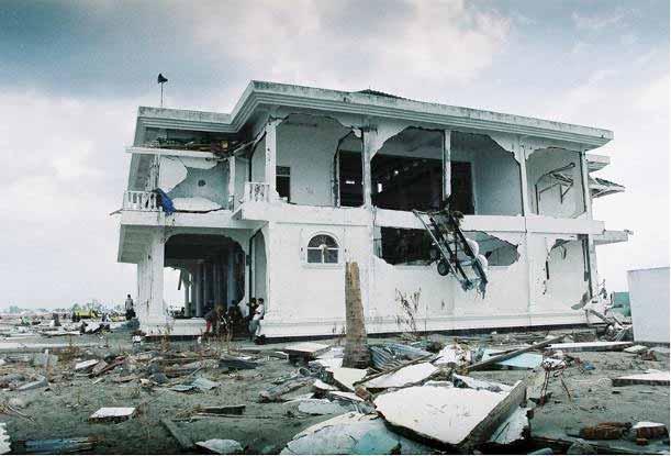
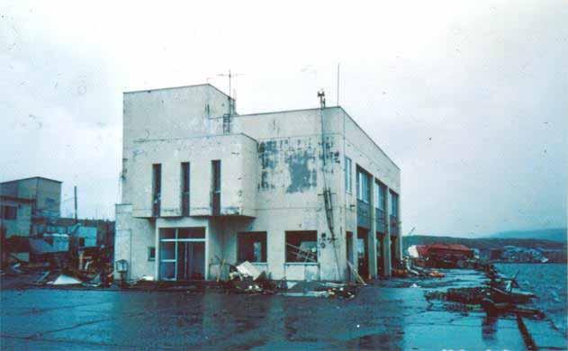
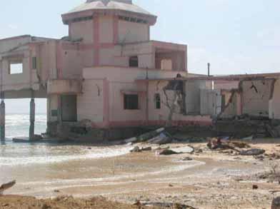
2 Building survival
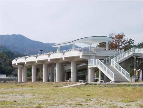
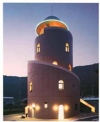
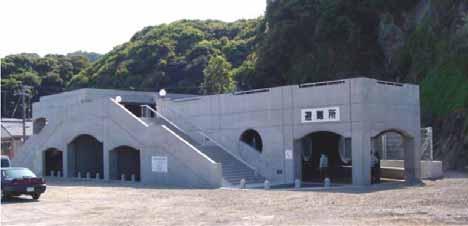
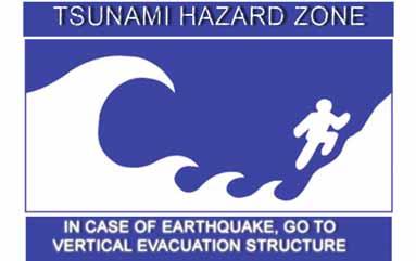
3 Vertical Evacuation to Tsunami Shelters
4 How can we estimate the tsunami forces on such onshore structures?
5 Force Category in the Present Codes City and County of Honolulu Building Code (2000) Hydrostatic Forces Buoyant Forces Hydrodynamic Forces Surge Forces Impact Forces Breaking Wave Forces

 A sketch of Scotch Cap Lighthouse (1946")
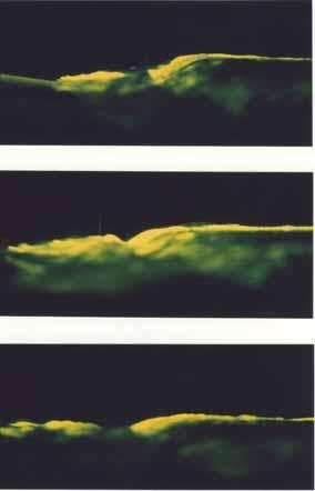
6 Wave breaking at the shore Typical when: steep beach slope narrow continental shelf A collapsing breaker resulted from an undular bore. (Yeh, et al. 1989) A sketch of Scotch Cap Lighthouse (1946 Aleutian Tsunami)
7 Some Considerations Tsunami shelters are located on land some distance away from the shoreline. Tsunami shelters are needed in the areas of relatively flat terrain where natural high-ground safe havens are not accessible. Formation of a surge may be the most likely flow condition. Wave breaking takes place offshore. The only exception is the collapsing breaker type, which occurs right at the shoreline on a steep-slope beach. We will not consider wave-breaking force
8 Force Category in the Present Codes Hydrostatic Forces Buoyant Forces Hydrodynamic Forces Surge Forces Impact Forces Breaking Wave Forces
9 Hydrostatic Force It is usually important for a 2-D structure such as seawalls and dikes, or for evaluation of an individual wall panel, but not for buildings F h = p c A w = g h max h w 2 bh w for h max > h w, else h max h w p c is the hydrostatic pressure at the centroid of the wetted portion of the wall panel, A w is the wetted area of the panel h max is the maximum water height above the base of the wall h w is the height of wall panel
")
10 Buoyant Force The buoyant forces act vertically through the center of mass of the displaced volume F B = gv Buoyant forces are a concern for wood frame buildings, empty above-ground and below-ground tanks. and, for evaluation of an individual floor panel where the water level outside is substantially higher than the level inside. (Lesson learned from Hurricane Katrina)

11 Case-by-case evaluation for hydrostatic force and buoyancy forces on an individual wall panel and a floor panel and alike. We only need the water depth h to compute the hydrostatic forces, which is readily estimated from the inundation maps
12 Force Category in the Present Codes Hydrostatic Forces Buoyant Forces Hydrodynamic Forces Surge Forces Impact Forces Breaking Wave Forces
13 Hydrodynamic Force When steady water flows around a building (or structural element or other object) hydrodynamic loads are applied to the building F D = 1 2 C D Au2 Drag Force Width to Depth Ratio Drag Coefficient Cd (w/ds or w/h) From > (FEMA CCM)
14 Hydrodynamic Force Force = 1 2 C d A f u 2 bhu 2 h: water depth u: flow velocity b: breadth Laboratory Data of Tsunami Force on a Squire Column: C d Surge force Hydrodynamic force C d O (1) 2 But, how do we determine the value of h u 2?

15 Force Category in the Present Codes Hydrostatic Forces Buoyant Forces Hydrodynamic Forces Surge Forces Impact Forces Breaking Wave Forces
16 Surge Force (present codes) Surge forces are caused by the leading edge of a surge of water impinging on a structure F s = 4.5 gh 2 b F s b = 1 2 gh2 + u 2 h: u = 2 gh Keulegan (1950) The identical approach by the Building Center of Japan h is the surge height -- how can we determine? u = 2 gy

17 Ramsden, 1993
18 Bore vs Surge No initial water-impact force in dry-bed surges Comparison of the experimental a) wave profile; b) runup; c) pressure head; and d) force due to a strong turbulent bore and a dry bed surge (after Ramsden, 1993)

19 Force Category in the Present Codes Hydrostatic Forces Buoyant Forces Hydrodynamic Forces Surge Forces Impact Forces Breaking Wave Forces
20 Impact Force Impact loads are those that result from debris such as driftwood, small boats, portions of houses, etc., or any object transported by floodwaters, striking against buildings and structures

21 Lincoln City, Oregon Driftwood becomes hazardous
22 Impact Force (present codes) F I = m du dt = m u I t Type of construction Duration (t) of Impact (sec) Wall Pile Wood Steel NA Reinforced Concrete Concrete Masonry (FEMA CCM) This is based on the impulse-momentum approach: I = 0 Fdt = dmu ( ); 0
23 ASCE 7-02 Relevant Literature ASCE Standard Minimum design loads for buildings and other structures. SEI/ASCE City and County of Honolulu Building Code (CCH, 2000) Matsutomi J. Hydr., Coastal, Envr. Engrg., 621, 1999 & Tsunami Engineering Tech. Rep., 13, 1996 Ikeno, et al. 2001, Impulse Force of Drift Body Haehnel and Daly USACOE Report, ERDC/CRREL TR-02-2
24 ASCE 7-02 (2003) F = muc I C O C D C B R max 2 t m: the debris mass, u: the impact velocity of object, C i : the importance coefficient, C O : the orientation coefficient, C D : the depth coefficient, C B : the blockage coefficient, R max : the maximum response ratio for impulsive load t: the impact duration: t = 0.03 sec is recommended City and County of Honolulu Building Code (2000) recommends t = 1.0 sec for wood construction, t = 0.5 sec for steel construction, and t = 0.1 sec for reinforced concrete FEMA CCM, t = 0.2 ~ 1.1 sec
25 Matsutomi: J. Hydr., Coastal, Envr. Engrg., 621, 1999 & Tsunami Engineering Tech. Rep., 13, 1996 Impact force evaluation: F = M dv dt t F ( t) dt = C M MV 0 0 F w D 2 L = 1.6C M u gd 1.2 f w L 0.4 Specifically for lumber impact Using small-scale laboratory experiments, C M = 1.7 (C M = 1.9 for steady flows) Use large-scale dry experiments, u: impact velocity w : specific weight of lumber f : yield stress of lumber ( compressive strength) ~ 20 MPa D: diameter of lumber L: length of lumber
26 Matsutomi s work
27 Haehnel and Daly, 2002 Lumber impact 0; m s» m l ; k s» k t, k l 1 ˆ k = 1 k t + 1 k l m 1 x + ˆk x= 0 x = u m sin t ˆk ˆk m F = ˆkx F max = Max. ˆkx = u ˆkm

28 1.22 x 0.61 x 36.6 m flume. 9.1 x 37 x 2.4 m basin Experiments by Haehnel & Daly
29 Constant Stiffness Approach: Haehnel and Daly F max = Max. ˆkx = u ˆkm 1550u m From their experiments, the effective constant stiffness is 2.4 MN/m (but no flow in their experiments) Impulse-Momentum Approach: F max = 2 um t The impulse-momentum approach reduces to the constant stiffness approach by setting Work-Energy Approach: F max = u2 m x 90.9um 125 mu The work-energy approach reduces to the constant stiffness approach by setting t = 2 x = u m ˆk m ˆk
30 Comments Uncertainty may be resulted from the fact that the prediction models are based on the empirical scaled-down (and small) data. All of the previous works are for impact of a relatively small water-borne missile, e.g. a lumber log. No consideration was made for impact of a large missile such as a ship.
31 Comments Different relations based on the model: Constant Stiffness Approach F u m n = 0.50 Impulse-Momentum Approach F um Work-Energy Approach F u 2 m Ikeno et al. (2003) F u 2.5 m n n 0.58 Matsutomi (1999) F u 1.2 m n n 0.66 Impulse-Momentum Approach: Work-Energy Approach: t = 2 x = u m ˆk m ˆk
32 Summary & Recommendations Forces on a building examined for a tsunami shelter. Hydrodynamic force with C D = 2. Surging force may not be important, but if we consider bore formation, this can be taken into account by using C D = 3 instead of 2. F D = 1 2 C D bhu2 Impact force can be evaluated by the modified constant stiffness approach with an appropriate value of effective stiffness k, and the added mass coefficient C M ( 2). k = 2.4MN/m was recommended for a lumber F max = C M u ˆkm
33 Recommendations - continue Need the design values of h, u, hu 2 at the site of interest. Note that: Max (hu 2 ) Max (h) Max (u 2 ) Obtain the data from detailed numerical simulations with a very fine grid size in the runup zone ( < 10 m). As for a guideline, use of the analytical solutions for 1-D runup on a uniformly sloping beach.

34 A snap shot of numerical simulation Available inundation map
35 Maximum hu 2 distribution in the runup zone (analytic solution for 1-D runup on a uniformly sloping beach) hu 2 g 2 = 0.11 ( x ) ( x ). Max. inundation Yeh (2006) Shore line
36 To obtain the design values of h, u, hu 2 at the site of interest Long-Wave Runup on a Plane Beach Nonlinear Problem Carrier and Greenspan (1958) Carrier, Wu, and Yeh (2003) -- Analytic-Numeric Hybrid Approach 0 x
37 The fully nonlinear shallow-water wave [ u' ( x' + ' )] x' + ' t ' = 0, u' t' + u' u' x' + g' x' = 0, Scaling: u' = g L u; ' = L; x' = Lx; t' = L g t [ ux+ ( ) ] x + t = 0, u t + uu x + x = 0.
38 Introducing the distorted coordinates q and such that: = t u; q = x + The transformation yields: ( qu) q + + u 2 2 u + + u2 2 q = 0. = 0, = + u2 2 = q = x +
39 4 ( ) = 0 where = + u2 2 The same form as the one by Carrier-Greenspan (1958). For convenience, we introduce the variable : = + u 2 2 = ; u = 2 ; = ( ) = 0 Initial Conditions at = t u = 0:,0 ( )= P( ), (,0)= F ( ), ( ) P( )= 2' u( ',0) d', and F( )=,0 ( )+ u2,0 0 2.
40 Summary 4 ( ) = 0, ( )= 2 Fb { ( ) Gb,, ( )db + Pb ( ) G 0 0 ( b,,) } db With ICs: ( ) P( )= 2' u( ',0) d', and F( )=,0 ( )+ u2, = + u 2 2 = ; u = 2 ; = = t u; = x +
41 The initial wave form of a Gaussian shape x
42 (, ) for the Gaussian shaped initial displacement Lambda Sigma
43 Water-surface plot for the Gaussian shaped initial displacement 4.0 t x
44 Water-surface profile at t = x

45 Water-depth variations: q (a) t t x q

46 Water velocity: u (a) 3.5 t 3.0 t x u
47 Momentum Flux (Fluid Force) h u (a) 3.0 t x x q*u^2
48 Initial Waveforms x x x x
 1.5-0.05 0.00 0.05 0.10 0.15 (d) 3.")


49 (a) Fluid Forces (b) x (c) (d) q*u^ q*u^2 t 2.5 t x x q*u^ q*u^2
50 Maximum force distribution from the maximum runup qu 2 gd Location of the initial shoreline LS NW Gaussian Ng-Gaussian X/L from the maximum runup
51 Maximum hu 2 distribution in the runup zone (analytic solution for 1-D runup on a uniformly sloping beach) hu 2 g 2 = 0.11 ( x ) ( x ). Max. inundation Yeh (2006) Shore line
52 Hydrodynamic and Surge Forces Hydrodynamic force with C D = 2. Surging force may not be important, but if we consider bore formation, this can be taken into account by using C D = 3 instead of 2. F D = 1 2 C D bhu2 h max R z datum l x hu 2 g 2 = 0.11 ( x ) ( x ) based on the distance hu 2 gr = z 2 R z R 2 based on the elevation
53 Impact Force max. u Impact force can be evaluated by the modified constant stiffness approach with an appropriate value of effective stiffness k, and the added mass coefficient C M ( 2). k = 2.4MN/m was recommended for a lumber. F I = C M u ˆkm

54 Bore Runup Process
55 Analytical Solution to Determine u max Maximum flow-speed u distribution in the runup zone: at the leading tongue of a surge front where the depth d = 0. uniform bore Ho and Meyer (1962) Yeh et al. (1989) u max = u max = 2 g ( x) 2 gr 1 z R u 2 g tan Yeh (2006) x

56 Floating debris with a finite draft draft Nagappattinam, India, 2004
57 Analytical solution to determine u max for a floatable debris with a finite draft The upper limit of flow-speed u for the depth d: d can be the draft of a floating debris. For bore runup, based on Shen and Meyer (1963), Peregrine and Williams (2001) presented: = 1 ( ) = 1 ( ) where = d R ; = u 2 gr ; = t g R ; = z R
58 The max. flow velocity R = maximum runup elevation. z = ground elevation d = flow depth d/r = (1) 0, (2) , (3) 0.01, (4) 0.02, (5) 0.04, (6) 0.06, (7) 0.08, (8) 0.10, and (9) 0.12.
59 Example Maximum runup height R = 10 m. Beach slope = 1/50 (= 0.02) Location of the shelter 100 m from the shoreline (z = 2 m), and the shelter breadth b = 10 m. Drift wood -- mass = 450 kg; effective stiffness k = N/m Shipping container -- mass = 30,000kg; 12.2m 2.44 m 2.59m h max = 8 m = 1025 kg/m 3 for sea water h max R = 10 m z = 2 m datum
60 Hydrodynamic and surge forces: Example ( hu 2 ) = gr z max R z R F d = 1 2 C B d ( ) hu2 max ( 1025 kg m3) ( 3.0) ( 10 m) ( 80.8 m 3 sec 2 ) = 1 2 = 1240 kn Impact forces (drift wood): 2 = 80.8 m3 sec 2 u max = 2 gr 1 z R = 12.5 m sec. F i = C m u max km = 2.0( 12.5 m sec) ( N m) ( 450 kg) = 822 kn
61 Impact force (shipping container): Example draft d is: d = = W A box kg ( 1025 kg m 3 ) 12.2 m 2.44 m ( ) = 0.98 m At the location of the shelter site, = z/r = 0.2, and the flow depth, d/r = The figure shows u max along the limit curve at = Hence, the maximum velocity is: u max = gr = 2.5 m sec. F i = C m u max km = 2.0( 2.5 m sec) ( N m) ( kg) = 1340 kn
62 1) d/r = 0, 2) , 3) 0.01, 4) 0.02, 5) 0.04, 6) 0.06, 7) 0.08, 8) 0.10, and 9) 0.12
GENERAL SOLUTIONS FOR THE INITIAL RUN-UP OF A BREAKING TSUNAMI FRONT
 International Symposium Disaster Reduction on Coasts Scientific-Sustainable-Holistic-Accessible 14 16 November 2005 Monash University, Melbourne, Australia GENERAL SOLUTIONS FOR THE INITIAL RUN-UP OF A
Large scale smooth particle hydrodynamics model for analytical fragility curves of a building subject to tsunami
 Large scale smooth particle hydrodynamics model for analytical fragility curves of a building subject to tsunami *Fritz Sihombing 1) and Marco Torbol 2) 1), 2) School of Urban and Environment Engineering,
Experimental Study for Investigating the Impact Force on a Wooden House by Driftwood in Steady and Unsteady Surge-type Flow
 Experimental Study for Investigating the Impact Force on a Wooden House by Driftwood in Steady and Unsteady Surge-type Flow K. Miyahara 1 and N. Tanaka 2 1 Graduate School of Science and Engineering, Saitama
Tsunami. Harry Yeh Oregon State University. Eastern Japan Earthquake Disaster Briefing at PEER: April 28, 2011
 Tsunami by Harry Yeh Oregon State University Eastern Japan Earthquake Disaster Briefing at PEER: April 28, 2011 Seismic Characteristics Rupture Model (Harvard Seismology) The fault rupture process was
1475. Structural dynamic response analysis on structure under tsunami bore impact
 1475. Structural dynamic response analysis on structure under tsunami bore impact Tie Cheng Wang 1, Tao Meng 2, Hai Long Zhao 3 1, 2, 3 School of Civil Engineering, Tianjin University, Tianjin, 300072,
INFLUENCE OF A INFRASTRUCTURE ON TSUNAMI INUNDATION IN A COASTAL CITY: LABORATORY EXPERIMENT AND NUMERICAL SIMULATION
 INFLUENCE OF A INFRASTRUCTURE ON TSUNAMI INUNDATION IN A COASTAL CITY: LABORATORY EXPERIMENT AND NUMERICAL SIMULATION Sungwon Shin 1, Kwang-Ho Lee 1, Hyungsu Park 2, Daniel T. Cox 2, Kyuhan Kim 1 Laboratory
RESPONSE OF STRUCTURES AGAINST TSUNAMI FORCES UNDER DIFFERENT SOIL CONDITIONS
 VOL. 13, NO. 11, JUNE 218 ISSN 1819-668 26-218 Asian Research Publishing Network (ARPN). All rights reserved. RESPONSE OF STRUCTURES AGAINST TSUNAMI FORCES UNDER DIFFERENT SOIL CONDITIONS A. H. L.Swaroop
Response characteristics of R/C buildings considering impulsive force of tsunami drifting objects
 Response characteristics of R/C buildings considering impulsive force of tsunami drifting objects Ho CHOI 1, Kazuto MATSUKAWA 2 and Yoshiaki NAKANO 3 1 Research Associate, Institute of Industrial Science,
SCIENCE OF TSUNAMI HAZARDS
 SCIENCE OF TSUNAMI HAZARDS ISSN 8755-6839 Journal of Tsunami Society International Volume 32 Number 2 2013 IMPACT OF TSUNAMI FORCES ON STRUCTURES The University of Ottawa Experience D. Palermo, I. Nistor
Shoaling of Solitary Waves
 Shoaling of Solitary Waves by Harry Yeh & Jeffrey Knowles School of Civil & Construction Engineering Oregon State University Water Waves, ICERM, Brown U., April 2017 Motivation The 2011 Heisei Tsunami
storage tank, or the hull of a ship at rest, is subjected to fluid pressure distributed over its surface.
 Hydrostatic Forces on Submerged Plane Surfaces Hydrostatic forces mean forces exerted by fluid at rest. - A plate exposed to a liquid, such as a gate valve in a dam, the wall of a liquid storage tank,
Designing Bridges for Tsunami Hazard
 Designing for Tsunami Hazard Patrick Lynett, University of Southern California With major technical contributions from: Hong Kie Thio, Michael Scott, Ian Buckle, Dennis Istrati, Tom Murphy The project
AN EXPERIMENTAL STUDY ON SAND DUNE SEDIMENT TRANSPORT DUE TO TSUNAMI OVERWASH. K M Ahtesham Hossain Raju 1 and Shinji Sato 2
 AN EXPERIMENTAL STUDY ON SAND DUNE SEDIMENT TRANSPORT DUE TO TSUNAMI OVERWASH K M Ahtesham Hossain Raju 1 and Shinji Sato 2 Response of sand dune when overwashed by tsunami or storm surge, is investigated
23. A force in the negative direction of an x-axis is applied for 27ms to a 0.40kg ball initially moving at 14m/s in the positive direction of the
 23. A force in the negative direction of an x-axis is applied for 27ms to a 0.40kg ball initially moving at 14m/s in the positive direction of the axis. The force varies in magnitude, and the impulse has
Mooring Model for Barge Tows in Lock Chamber
 Mooring Model for Barge Tows in Lock Chamber by Richard L. Stockstill BACKGROUND: Extensive research has been conducted in the area of modeling mooring systems in sea environments where the forcing function
Numerical Modeling of Extreme Flow Impacts on Structures
 Numerical Modeling of Extreme Flow Impacts on Structures Nora Asadollahi Shahbaboli Thesis submitted to the Faculty of Graduate and Postdoctoral Studies in partial fulfillment of the requirements for the
Alongshore Momentum Balance: Currents
 Chapter 16 Alongshore Momentum Balance: Currents Two assumptions are necessary to get a simple equation for v. The first is that the flow is steady so that time derivatives can be neglected. Second, assume
Ed Curtis, PE, CFM, FEMA Region IX and Darryl Hatheway, CFM, AECOM ASFPM 2016, Grand Rapids, MI
 Methodology to Determine Process-Based Total Water Level Profiles in Areas Dominated by Wave Runup Ed Curtis, PE, CFM, FEMA Region IX and Darryl Hatheway, CFM, AECOM ASFPM 2016, Grand Rapids, MI Thurs.
6 September Professor Harry Yeh Civil, Construction & Environmental Engineering 220 Owen Hall Oregon State University Corvallis, OR
 1 Robert L. Wiegel Professor Emeritus Department of Civil & Environmental Engineering 410 O'Brien Hall, MC 1718 University of California, Berkeley, California 94720-1718 Professor Harry Yeh Civil, Construction
UNDERSTANDING TSUNAMI RISK TO STRUCTURES: A CANADIAN PERSPECTIVE
 UNDERSTANDING TSUNAMI RISK TO STRUCTURES: A CANADIAN PERSPECTIVE ABSTRACT : D. Palermo 1 and I. Nistor 1 1 Assistant Professor, Dept. of Civil Engineering, University of Ottawa, Ottawa, Canada Email: palermo@eng.uottawa.ca,
An empirical solution for tsunami run-up on compound slopes
 An empirical solution for tsunami run-up on compound slopes Park, H., Cox, D. T., & Petroff, C. M. (2015). An empirical solution for tsunami run-up on compound slopes. Natural Hazards, 76(3), 1727-1743.
THE DEPOSITS OF TSUNAMIS WESLEY PESANTEZ, CATHERINE NIELD, COLIN WINTER
 THE DEPOSITS OF TSUNAMIS WESLEY PESANTEZ, CATHERINE NIELD, COLIN WINTER AN OVERVIEW OF OUR SEMINAR WHAT IS A TSUNAMI WHY STUDY TSUNAMIS PROPERTIES OF TSUNAMIS TSUNAMI HYDRODYNAMICS IDEALIZED DEPOSITS SEDIMENT
AN ABSTRACT OF THE THESIS OF
 AN ABSTRACT OF THE THESIS OF Sutaporn Boon-intra for the degree of Master of Science in Civil Engineering presented on November 30, 2010 Title: Development of a Guideline for Estimating Tsunami Forces
NUMERICAL SIMULATION OF LONG WAVE RUNUP ON A SLOPING BEACH*
 NUMERICAL SIMULATION OF LONG WAVE RUNUP ON A SLOPING BEACH* * presented at Long Waves Symposium (in parallel with the XXX IAHR Congress) August 5-7, 003, AUTh, Thessaloniki, Greece. by HAKAN I. TARMAN
Comparative Analysis on Response of a School Building against Gravity, Earthquake and Tsunami forces
 Comparative Analysis on Response of a School Building against Gravity, Earthquake and Tsunami forces P. Subhash Bhargava 1, A.H.L.Swaroop 2 1Post Graduate student, Gudlavalleru Engineering College, Gudlavalleru,
UNDERSTANDING TSUNAMI RISK TO STRUCTURES: A CANADIAN PERSPECTIVE
 UNDERSTANDING TSUNAMI RISK TO STRUCTURES: A CANADIAN PERSPECTIVE D. Palermo 1 and I. Nistor 1 1 Assistant Professor, Dept. of Civil Engineering, University of Ottawa, Ottawa, Canada Email: palermo@eng.uottawa.ca,
DEVELOPMENT OF TSUNAMI DESIGN CRITERIA FOR OREGON COASTAL BRIDGES. Bruce Johnson 1 Based on research and documents by Solomon Yim 2 et al
 DEVELOPMENT OF TSUNAMI DESIGN CRITERIA FOR OREGON COASTAL BRIDGES Bruce Johnson 1 Based on research and documents by Solomon Yim 2 et al Abstract This paper describes Oregon Department of Transportation
ENERGY DIAGRAM w/ HYSTERETIC
 ENERGY DIAGRAM ENERGY DIAGRAM w/ HYSTERETIC IMPLIED NONLINEAR BEHAVIOR STEEL STRESS STRAIN RELATIONSHIPS INELASTIC WORK DONE HYSTERETIC BEHAVIOR MOMENT ROTATION RELATIONSHIP IDEALIZED MOMENT ROTATION DUCTILITY
Weather Middle School Teacher Instructions and Activity
 Weather Middle School Teacher Instructions and Activity Based on the guidelines of the Saffir-Simpson Scale for hurricane severity and the Fujita Scale for tornado damage, students will write a brief synopsis
Chapter 2 Hydrostatics Buoyancy, Floatation and Stability
 Chapter 2 Hydrostatics uoyancy, Floatation and Stability Zerihun Alemayehu Rm. E119 AAiT Force of buoyancy an upward force exerted by a fluid pressure on fully or partially floating body Gravity Archimedes
TSUNAMI INUNDATION MODELING: SENSITIVITY OF VELOCITY AND MOMENTUM FLUX TO BOTTOM FRICTION WITH APPLICATION TO BUILDING DAMAGE AT SEASIDE, OREGON
 TSUNAMI INUNDATION MODELING: SENSITIVITY OF VELOCITY AND MOMENTUM FLUX TO BOTTOM FRICTION WITH APPLICATION TO BUILDING DAMAGE AT SEASIDE, OREGON Hyoungsu Park 1, Dane Wiebe 2, Daniel Cox 3, and Katherine
DRAFT - Tsunami Response Plan Playbook Santa Cruz Harbor Maritime Community
 DRAFT - Tsunami Response Plan Playbook Santa Cruz Harbor Maritime Community Page 1 Best to display on 11X17 paper Purpose and Use of this Real-time Tsunami Response Plan Playbook PURPOSE: This product
INFLUENCE OF TSUNAMI INDUCED SCOURING ACTION ON FOUNDATION STABILITY OF COASTAL STRUCTURES
 International Journal of Civil Engineering and Technology (IJCIET) Volume 9, Issue 7, July 2018, pp. 889 894, Article ID: IJCIET_09_07_093 Available online at http://www.iaeme.com/ijciet/issues.asp?jtype=ijciet&vtype=9&itype=7
Paul de Groot. The thesis committee consists of: Prof. dr. ir. M.J.F. Stive Prof. dr. ir. L.C. Van Rijn Ir. S.G.J. Aarninkhof Ir. G.
 Preface This thesis is the result of a study, investigating the swash zone sediment transport processes. The first part of the thesis work has taken place on the University of Queensland, in Brisbane,
NUMERICAL ANALYSIS OF TSUNAMI FLOW AROUND COASTAL DYKE
 Proceedings of the 7 th International Conference on Asian and Pacific Coasts (APAC 2013) Bali, Indonesia, September 24-26, 2013 NUMERICAL ANALYSIS OF TSUNAMI FLOW AROUND COASTAL DYKE T. Mikami 1 and T.
Chapter 1 INTRODUCTION
 Chapter 1 INTRODUCTION 1-1 The Fluid. 1-2 Dimensions. 1-3 Units. 1-4 Fluid Properties. 1 1-1 The Fluid: It is the substance that deforms continuously when subjected to a shear stress. Matter Solid Fluid
GRAIN-SIZE SORTING IN THE SWASH ZONE ON UNEQUILIBRIUM BEACHES AT THE TIMESCALE OF INDIVIDUAL WAVES
 GRAIN-SIZE SORTING IN THE SWASH ZONE ON UNEQUILIBRIUM BEACHES AT THE TIMESCALE OF INDIVIDUAL WAVES Tetauya Kakinoki 1, Gozo Tsujimoto 1 and Kohji Uno 1 The purpose of this study is to investigate sediment
Tsunami wave impact on walls & beaches. Jannette B. Frandsen
 Tsunami wave impact on walls & beaches Jannette B. Frandsen http://lhe.ete.inrs.ca 27 Mar. 2014 Tsunami wave impact on walls & beaches Numerical predictions Experiments Small scale; Large scale. Numerical
Insurer-Funded Non-Profit Promotes Resilient Construction Research & Communications. Tornado Proof Near Ultimate Protection Tornado Resistant
 Who is IBHS Tornado Resistant Construction: Design Issues Plus Pros and Cons of Various Building Systems Timothy Reinhold Sr. VP for Research, Chief Engineer Insurance Institute for Business & Home Safety
Numerical simulation of wave overtopping using two dimensional breaking wave model
 Numerical simulation of wave overtopping using two dimensional breaking wave model A. soliman', M.S. ~aslan~ & D.E. ~eeve' I Division of Environmental Fluid Mechanics, School of Civil Engineering, University
B O S Z. - Boussinesq Ocean & Surf Zone model - International Research Institute of Disaster Science (IRIDeS), Tohoku University, JAPAN
, Tohoku University, JAPAN") B O S Z - Boussinesq Ocean & Surf Zone model - Volker Roeber 1 Troy W. Heitmann 2, Kwok Fai Cheung 2, Gabriel C. David 3, Jeremy D. Bricker 1 1 International Research Institute of Disaster Science (IRIDeS),
B O S Z - Boussinesq Ocean & Surf Zone model - Volker Roeber 1 Troy W. Heitmann 2, Kwok Fai Cheung 2, Gabriel C. David 3, Jeremy D. Bricker 1 1 International Research Institute of Disaster Science (IRIDeS),
SURGE IMPACT LOADING ON WOOD RESIDENTIAL STRUCTURES
 SURGE IMPACT LOADING ON WOOD RESIDENTIAL STRUCTURES Jason Miles, REU (Research Experience for Undergraduates) Student Home Institution: Louisiana State University REU Institution: Oregon State University
Swash Zone Dynamics: Modeling and Data Analysis
 Swash Zone Dynamics: Modeling and Data Analysis Donald N. Slinn Department of Civil and Coastal Engineering University of Florida Gainesville, FL 32611-6590 phone: (352) 392-1436 x 1431 fax: (352) 392-3466
The Marine Environment
 The Marine Environment SECTION 16.1 Shoreline Features In your textbook, read about erosional landforms, beaches, estuaries, longshore currents, and rip currents. For each statement below, write or. 1.
INTEGRATED SIMULATION OF TSUNAMI HAZARDS ABSTRACT
 INTEGRATED SIMULATION OF TSUNAMI HAZARDS Toshitaka Katada 1 Noriyuki Kuwasawa 2, Harry Yeh 3, and Cherri Pancake 4 ABSTRACT It is impractical to give warning and evacuate people from the direct effects
The Marine Environment
 The Marine Environment SECTION 16.1 Shoreline Features In your textbook, read about erosional landforms, beaches, estuaries, longshore currents, and rip currents. For each statement below, write true or
Tsunami potential and modeling
 Tsunami potential and modeling GEORGE PRIEST OREGON DEPT. OF GEOLOGY AND MINERAL INDUSTRIES NEWPORT COASTAL FIELD OFFICE April 7, 2012 GeoPRISMS Cascadia Workshop, Portland, Oregon What creates most uncertainty
DEVELOPMENT OF A COMPRESSED CARBON DIOXIDE PROPULSION UNIT FOR NEAR-TERM MARS SURFACE APPLICATIONS
 DEVELOPMENT OF A COMPRESSED CARBON DIOXIDE PROPULSION UNIT FOR NEAR-TERM MARS SURFACE APPLICATIONS Erin Blass Old Dominion University Advisor: Dr. Robert Ash Abstract This work has focused on the development
Earthquake Hazards. Tsunami
 Earthquake Hazards Tsunami Measuring Earthquakes Two measurements that describe the power or strength of an earthquake are: Intensity a measure of the degree of earthquake shaking at a given locale based
New Website: M P E il Add. Mr. Peterson s Address:
 Brad Peterson, P.E. New Website: http://njut009fall.weebly.com M P E il Add Mr. Peterson s Email Address: bradpeterson@engineer.com If 6 m 3 of oil weighs 47 kn calculate its If 6 m 3 of oil weighs 47
CHAPTER 34. ANAimCAL APPROACH ON WAVE OVERTOPPING ON LEVEES. Hiroyoshi Shi-igai, Dr Eng,M Eng,M of JSCE.* Tsugio Kono, B Eng,M of JSCE**
 CHAPTER 34 ANAimCAL APPROACH ON WAVE OVERTOPPING ON LEVEES Hiroyoshi Shi-igai, Dr Eng,M Eng,M of JSCE.* Tsugio Kono, B Eng,M of JSCE** 1 Analytical Approach An analytical approach to evaluate the amount
and Engineering Laboratory Cold Regions Research Maximum Impact Force of Woody Debris on Floodplain Structures ERDC/CRREL TR-02-2
 ERDC/CRREL TR-02-2 US Army Corps of Engineers Engineer Research and Development Center Maximum Impact Force of Woody Debris on Floodplain Structures Robert B. Haehnel and Steven F. Daly February 2002 Cold
10.52 Mechanics of Fluids Spring 2006 Problem Set 3
 10.52 Mechanics of Fluids Spring 2006 Problem Set 3 Problem 1 Mass transfer studies involving the transport of a solute from a gas to a liquid often involve the use of a laminar jet of liquid. The situation
Well-balanced shock-capturing hybrid finite volume-finite difference schemes for Boussinesq-type models
 NUMAN 2010 Well-balanced shock-capturing hybrid finite volume-finite difference schemes for Boussinesq-type models Maria Kazolea 1 Argiris I. Delis 2 1 Environmental Engineering Department, TUC, Greece
Three Fs of earthquakes: forces, faults, and friction. Slow accumulation and rapid release of elastic energy.
 Earthquake Machine Stick-slip: Elastic Rebound Theory Jerky motions on faults produce EQs Three Fs of earthquakes: forces, faults, and friction. Slow accumulation and rapid release of elastic energy. Three
Exploring the costs of sea level rise: should we focus on means or extremes?
 Exploring the costs of sea level rise: should we focus on means or extremes? Robert Muir-Wood Chief Research Officer, RMS AAAS Chicago Feb 16 th 2009 Change Points in Cat 3-5 Hurricane Numbers (the drivers
INERTIAL FORCES ON SHIPPING CONTAINERS FROM A BROKEN TSUNAMI BORE
 Proceedings of the 6 th International Conference on the Application of Physical Modelling in Coastal and Port Engineering and Science (Coastlab16) Ottawa, Canada, May 10-13, 2016 Copyright : Creative Commons
3 where g is gravity. S o and S f are bed slope and friction slope at x and y direction, respectively. Here, friction slope is calculated based on Man
 東北地域災害科学研究第 48 巻 () 3 D FORCE MUSCL SCHEME FOR SIMULATING BREAKING SOLITARY WAVE RUNUP Mohammad Bagus Adityawan * Hitoshi Tanaka ABSTRACT Breaking wave simulation using depth averaged based model, i.e.
What s New In ASCE 7-16?
 What s New In ASCE 7-16? Ronald O. Hamburger SE, SECB Senior Principal Simpson Gumpertz & Heger Inc. Presented to: TMS San Diego, CA Nov. 4 2017 www.sgh.com The Big Changes Title Change Chapter 1 Performance
THC-T-2013 Conference & Exhibition
 Modeling of Shutter Coastal Protection against Storm Surge for Galveston Bay C. Vipulanandan, Ph.D., P.E., Y. Jeannot Ahossin Guezo and and B. Basirat Texas Hurricane Center for Innovative Technology (THC-IT)
SHORELINE AND BEACH PROCESSES: PART 2. Implications for Coastal Engineering
 SHORELINE AND BEACH PROCESSES: PART 2 Implications for Coastal Engineering Objectives of the lecture: Part 2 Show examples of coastal engineering Discuss the practical difficulties of ocean engineering
STUDY ON DRIFT BEHAVIOR OF CONTAINER ON APRON DUE TO TSUNAMI-INDUCED INCOMING AND RETURN FLOW
 STUDY ON DRIFT BEHAVIOR OF CONTAINER ON APRON DUE TO TSUNAMI-INDUCED INCOMING AND RETURN FLOW Tomoaki Nakamura 1, Norimi Mizutani 2 and Yasuhiro Wakamatsu 3 The drift behavior of a shipping container on
Methodology for sloshing induced slamming loads and response. Olav Rognebakke Det Norske Veritas AS
 Methodology for sloshing induced slamming loads and response Olav Rognebakke Det Norske Veritas AS Post doc. CeSOS 2005-2006 1 Presentation overview Physics of sloshing and motivation Sloshing in rectangular
GFD 2013 Lecture 4: Shallow Water Theory
 GFD 213 Lecture 4: Shallow Water Theory Paul Linden; notes by Kate Snow and Yuki Yasuda June 2, 214 1 Validity of the hydrostatic approximation In this lecture, we extend the theory of gravity currents
The Sandbox Experiment
 Geological Sciences 101 Lab #7 - Introduction to Deformation Some of the most dramatic evidence that great forces have shaped the Earth are the rocks that one finds deformed in mountain belts. Rocks can
ρ mixture = m mixture /V = (SG antifreeze ρ water V antifreeze + SG water ρ water V water )/V, so we get
/V, so we get") CHAPTER 10 1. When we use the density of granite, we have m = ρv = (.7 10 3 kg/m 3 )(1 10 8 m 3 ) =.7 10 11 kg.. When we use the density of air, we have m = ρv = ρlwh = (1.9 kg/m 3 )(5.8 m)(3.8 m)(.8 m)
CHAPTER 10 1. When we use the density of granite, we have m = ρv = (.7 10 3 kg/m 3 )(1 10 8 m 3 ) =.7 10 11 kg.. When we use the density of air, we have m = ρv = ρlwh = (1.9 kg/m 3 )(5.8 m)(3.8 m)(.8 m)
SUPPLEMENTARY INFORMATION
 SUPPLEMENTARY INFORMATION DOI: 10.1038/NGEO1887 Diverse calving patterns linked to glacier geometry J. N. Bassis and S. Jacobs 1. Supplementary Figures (a) (b) (c) Supplementary Figure S1 Schematic of
Earthquake Hazards. Tsunami
 Earthquake Hazards Tsunami Review: What is an earthquake? Earthquake is the vibration (shaking) and/or displacement of the ground produced by the sudden release of energy. The point inside the Earth where
MULTIPLE-CHOICE PROBLEMS:(Two marks per answer) (Circle the Letter Beside the Most Correct Answer in the Questions Below.)
 (Circle the Letter Beside the Most Correct Answer in the Questions Below.)") MULTIPLE-CHOICE PROLEMS:(Two marks per answer) (Circle the Letter eside the Most Correct Answer in the Questions elow.) 1. The absolute viscosity µ of a fluid is primarily a function of: a. Density. b.
MULTIPLE-CHOICE PROLEMS:(Two marks per answer) (Circle the Letter eside the Most Correct Answer in the Questions elow.) 1. The absolute viscosity µ of a fluid is primarily a function of: a. Density. b.
Fluid Mechanics. Chapter 14. Modified by P. Lam 6_7_2012
 Chapter 14 Fluid Mechanics PowerPoint Lectures for University Physics, Twelfth Edition Hugh D. Young and Roger A. Freedman Lectures by James Pazun Modified by P. Lam 6_7_2012 Goals for Chapter 14 To study
s and FE X. A. Flow measurement B. properties C. statics D. impulse, and momentum equations E. Pipe and other internal flow 7% of FE Morning Session I
 Fundamentals of Engineering (FE) Exam General Section Steven Burian Civil & Environmental Engineering October 26, 2010 s and FE X. A. Flow measurement B. properties C. statics D. impulse, and momentum
Geol 117 Lecture 18 Beaches & Coastlines. I. Types of Coastlines A. Definition:
 I. Types of Coastlines A. Definition: 1. Shore = narrow zone where ocean meets land (e.g. beach) 2. Coast is a broad area where both ocean and land processes act a. Includes onshore marshes, dunes, sea
PRELIMINARY ANALYSIS OF WAVE SLAMMING FORCE RESPONSE DATA FROM TESTS ON A TRUSS STRUCTURE IN LARGE WAVE FLUME, HANNOVER, GERMANY
 NTNU Norwegian University of Science and Technology Department of Civil and Transport Engineering Report No.: IBAT/MB R1-213 Authors Christy Ushanth Navaratnam Alf Tørum Øivind A. Arntsen PRELIMINARY ANALYSIS
Chapter 4: Non uniform flow in open channels
 Chapter 4: Non uniform flow in open channels Learning outcomes By the end of this lesson, students should be able to: Relate the concept of specific energy and momentum equations in the effect of change
2016 NC Coastal Local Governments Annual Meeting
 6 NC Coastal Local Governments Annual Meeting NCFMP Coastal Map Maintenance Flood Study Updates and Changes April, 6 Tom Langan, PE, CFM Engineering Supervisor NCEM-Risk Management - Floodplain Mapping
COMPARATIVE STUDY OF LINEAR-ELASTIC AND NONLINEAR- INELASTIC SEISMIC RESPONSES OF FLUID-TANK SYSTEMS
 13 th World Conference on Earthquake Engineering Vancouver, B.C., Canada August 1-6, 2004 Paper No. 1127 COMPARATIVE STUDY OF LINEAR-ELASTIC AND NONLINEAR- INELASTIC SEISMIC RESPONSES OF FLUID-TANK SYSTEMS
Strategic approach towards Post Tsunami Mitigation and Conservation of the Sri Lankan coastline
 Strategic approach towards Post Tsunami Mitigation and Conservation of the Sri Lankan coastline Dr. S.S.L.Hettiarachchi Dr. S.P.Samarawickrama University of Moratuwa Illustrated via a Case Study for the
Environmental Geology Lab 6 Coastal Hazards. Tropical cyclones are classified based on substained wind speed as indicated below.
 Environmental Geology Lab 6 Coastal Hazards page - 1 In the continental United States there are two fundamental types of shorelines. Tectonically passive margins that have low relief and consist of smooth
Entrance exam Master Course
 - 1 - Guidelines for completion of test: On each page, fill in your name and your application code Each question has four answers while only one answer is correct. o Marked correct answer means 4 points
Impact of an oblique breaking wave on a wall
 PHYSICS OF FLUIDS VOLUME 6, NUMBER 3 MARCH 24 Jian-Jun Shu School of Mechanical & Production Engineering, Nanyang Technological University, 5 Nanyang Avenue, Singapore 639798 Received April 23; accepted
6.1 Momentum and Impulse A. What is momentum? Newton defined momentum as the quantity of motion
 AP Physics Mechanics Chapter 6 Momentum and Collisions Text chapter 6 - Reading pp. 141-161 - textbook HW -- #1,3,4,6,9,15,16,20,21,23,26,27,25,34,63,70,71 1 6.1 Momentum and Impulse A. What is momentum?
Transformation of irregular waves in the inner surf zone
 Transformation of irregular waves in the inner surf zone Philippe Bonneton and Hélène Dupuis 1 Abstract A numerical model based on a high order non-oscillatory MacCormack TVD scheme is presented for the
 Balcony balustrades using the SG12 laminated glass system: PAGE 1 (SG12FF010717) Structural Calculations for SG12 System balustrades using 21.5mm laminated toughened glass without the need for a handrail
Mechanism of tsunami generation,propagation and runup -sharing experiences with Japanese
 Mechanism of tsunami generation,propagation and runup -sharing experiences with Japanese Mechanism of tsunami generation Predicting the propagation, runup and inundation of tsunamis Near and far-field
5 ENERGY EQUATION OF FLUID MOTION
 5 ENERGY EQUATION OF FLUID MOTION 5.1 Introduction In order to develop the equations that describe a flow, it is assumed that fluids are subject to certain fundamental laws of physics. The pertinent laws
Structural, Snow & Wind Loading Appraisal Report
 Company Name Or Logo Here Structural, Snow & Wind Loading Appraisal Report In accordance with Guide to the Installation of Photovoltaic Systems 2012 2 nd Edition Reference number 001 Company Name Solar
Hull-tether-riser dynamics of deep water tension leg platforms
 Fluid Structure Interaction V 15 Hull-tether-riser dynamics of deep water tension leg platforms R. Jayalekshmi 1, R. Sundaravadivelu & V. G. Idichandy 1 Department of Civil Engineering, NSS College of
The Shallow Water Equations
 The Shallow Water Equations Clint Dawson and Christopher M. Mirabito Institute for Computational Engineering and Sciences University of Texas at Austin clint@ices.utexas.edu September 29, 2008 The Shallow
Liquids CHAPTER 13 FLUIDS FLUIDS. Gases. Density! Bulk modulus! Compressibility. To begin with... some important definitions...
 CHAPTER 13 FLUIDS FLUIDS Liquids Gases Density! Bulk modulus! Compressibility Pressure in a fluid! Hydraulic lift! Hydrostatic paradox Measurement of pressure! Manometers and barometers Buoyancy and Archimedes
KEYNOTE: ADVANCES IN EVALUATING TSUNAMI FORCES ON COASTAL STRUCTURES
 SECED 2015 Conference: Earthquake Risk and Engineering towards a Resilient World 9-10 July 2015, Cambridge UK KEYNOTE: ADVANCES IN EVALUATING TSUNAMI FORCES ON COASTAL STRUCTURES Tiziana ROSSETTO 1 Ian
MODELING INITIAL VELOCITY PROFILES FOR CONTINUOUS FREE-VIBRATING BEAMS USING DISTRIBUTED IMPULSE LOADING
 VOL. 1, NO. 9, MAY 17 ISSN 1819-668 6-17 Asian Research Publishing Network (ARPN). All rights reserved. MODELING INITIAL VELOCITY PROFILES FOR CONTINUOUS FREE-VIBRATING BEAMS USING DISTRIBUTED IMPULSE
SLOSH New Orleans Basin 2012 Update
 SLOSH New Orleans Basin 2012 Update Michael Koziara Science and Operations Officer National Weather Service Slidell, LA The Basics What is storm surge? What is SLOSH? Details Assumptions Inundation = Storm
RAPSODI Risk Assessment and design of Prevention Structures for enhanced tsunami DIsaster resilience
 RAPSODI Risk Assessment and design of Prevention Structures for enhanced tsunami DIsaster resilience Possible NGI contributions related to tsunami modelling activities Finn Løvholt and Carl B. Harbitz
Wainui Beach Management Strategy (WBMS) Summary of Existing Documents. GNS Tsunami Reports
 Summary of Existing Documents. GNS Tsunami Reports") Wainui Beach Management Strategy (WBMS) Summary of Existing Documents GNS Tsunami Reports a) Review of Tsunami Hazard and Risk in New Zealand ( National Risk Report ) b) Review of New Zealand s Preparedness
Wainui Beach Management Strategy (WBMS) Summary of Existing Documents GNS Tsunami Reports a) Review of Tsunami Hazard and Risk in New Zealand ( National Risk Report ) b) Review of New Zealand s Preparedness
BACHELOR OF TECHNOLOGY IN MECHANICAL ENGINEERING (COMPUTER INTEGRATED MANUFACTURING)
") No. of Printed Pages : 6 BME-028 BACHELOR OF TECHNOLOGY IN MECHANICAL ENGINEERING (COMPUTER INTEGRATED MANUFACTURING) Term-End Examination December, 2011 00792 BME-028 : FLUID MECHANICS Time : 3 hours
No. of Printed Pages : 6 BME-028 BACHELOR OF TECHNOLOGY IN MECHANICAL ENGINEERING (COMPUTER INTEGRATED MANUFACTURING) Term-End Examination December, 2011 00792 BME-028 : FLUID MECHANICS Time : 3 hours
Chapter 9: Solids and Fluids
 Chapter 9: Solids and Fluids State of matters: Solid, Liquid, Gas and Plasma. Solids Has definite volume and shape Can be crystalline or amorphous Molecules are held in specific locations by electrical
RESILIENT INFRASTRUCTURE June 1 4, 2016
 RESILIENT INFRASTRUCTURE June 1 4, 2016 OPTICAL TRACKING OF DEBRIS IN EXTREME HYDRODYNAMIC CONDITIONS Jacob Stolle University of Ottawa, Canada Ioan Nistor University of Ottawa, Canada Nils Goseberg Institute
DUNE EROSION NEAR SEA WALLS: MODEL-DATA COMPARISON
 DUNE EROSION NEAR SEA WALLS: MODEL-DATA COMPARISON Pieter van Geer 1, Bram de Vries 2, Ap van Dongeren 1 and Jaap van Thiel de Vries 1,2 This paper describes the validation of the dune erosion model XBeach
DREDGING DYNAMICS AND VIBRATION MEASURES
 DREDGING DYNAMICS AND VIBRATION MEASURES C R Barik, K Vijayan, Department of Ocean Engineering and Naval Architecture, IIT Kharagpur, India ABSTRACT The demands for dredging have found a profound increase
Redcliffs Park Coastal inundation and coastal erosion
 48 Hereford Street Christchurch 8013 Attention: Deb Taylor Dear Deb 1 Introduction The (MoE) are looking to relocate Redcliffs School to a new school development at and are currently undertaking their