Lecture Set 1 Introduction to Magnetic Circuits
|
|
|
- Linda Evans
- 6 years ago
- Views:
Transcription
1 Lecture Set 1 Introduction to Magnetic Circuits S.D. Sudhoff Spring
2 Goals Review physical laws pertaining to analysis of magnetic systems Introduce concept of magnetic circuit as means to obtain an electric circuit Learn how to determine the flux-linkage versus current characteristic because it will be key to understanding electromechanical energy conversion 2
3 Review of Symbols Flux Density in Tesla: B (T) Flux in Webers: Φ (Wb) Flux Linkage in Volt-seconds: λ (Vs,Wb-t) Current in Amperes: i (A) Field Intensity in Ampere/meters: H (A/m) Permeability in Henries/meter: µ (Η/m) Magneto-Motive Force: F (A,A-t) Permeance in Henries: P (H) Reluctance in inverse Henries: R (1/H) Inductance in Henries: L (H) Current (fields) into page: Current (fields) out of page: 3
4 Ampere s Law, MMF, and Kirchoff s MMF Law for Magnetic Circuits 4
5 Consider a Closed Path 5
6 Enclosed Current and MMF Sources Enclosed Current i Γ = N i + N i N i enc, a a b b c c MMF Sources F F a b = N i = N i b b a a F c = N i c c Conclusion i enc, Γ = Fs SΓ = {' a ',' b',' c '} s S Γ 6
7 MMF Drops Going Around the Loop MMF Drop F y Thus Or H d l = H d l + H d l + H d l + H d l l l l lγ l Γ = H d l l y H d l = α β δ H d l = F + F + F + F l Τ F d DΓ = {' α ',' β ',' γ ',' δ '} l d DΓ Γ α β γ δ 7
8 Ampere s Law Ampere s Law H d l = i l Γ Recall i enc, Γ Thus = s S Γ enc, Γ F F = s s S d D Γ s Γ F d H d l = l Γ d D Γ F d 8
9 Kirchoff s MMF Law Kirchoff s MagnetoMotive Force Law: The Sum of the MMF Drops Around a Closed Loop is Equal to the Sum of the MMF Sources for That Loop 9

10 Example: MMF Sources 10 conductors, 3 A = 5 conductors, 2 A = 10
11 Example: MMF Drops A quick example on MMF drop: 11
12 Another Example: MMF Drops How about F cb? 12
13 Magnetic Flux, Gauss s Law, and Kirchoff s Flux Law for Magnetic Circuits 13

14 Magnetic Flux Φ m = B S m ds 14
15 Example: Magnetic Flux Suppose there exist a uniform flux density field of B=1.5a y T where a y is a unit vector in the direction of the y-axis. We wish to calculate the flux through open surface S m with an area of 4 m 2, whose periphery is a coil of wire wound in the indicated direction. 15
16 Example: Magnetic Flux 16
17 Example: Magnetic Flux 17
18 Kirchoff s Flux Law Gauss s Law Thus Or B d S = S Γ o O Γ S o Φ o = o O Γ 0 B ds O Γ = {' α ',' β ', ' γ ', } 0 18
19 Kirchoff s Flux Law Kirchoff s Flux Law: The Sum of the Flux Leaving A Node of a Magnetic Circuit is Zero 19
20 Kirchoff s Flux Law A quick example on Kirchoff s Flux Law 20
21 Magnetically Conductive Materials and Ohm s Law for Magnetic Circuits 21
22 Ohm s Law On Ohm s Law Property for Electric Circuits On Ohm s Law Property for Magnetic Circuits 22
23 Types of Magnetic Materials Interaction of Magnetic Materials with Magnetic Fields Magnetic Moment of Electron Spin Magnetic Moment of Electron in Shell These Effects Lead to Six Material Types Diamagnetic Paramagnetic Ferromagnetic Antiferromagnetic Ferrimagnetic Superparamagnetic 23
24 Ferromagnetic Materials Iron Nickel Cobalt 24
25 Ferrimagnetic Materials Iron-oxide ferrite (Fe 3 O 4 ) Nickel-zinc ferrite (Ni 1/2 Zn 12 Fe 2 O 4 ) Nickel ferrite (NiFe 2 O 4 ) 25
26 Behavior of Ferromagnetic and Ferrimagnetic Materials 26


27 Behavior of Ferromagnetic and Ferrimagnetic Materials M19 MN80C 27
28 Modeling Magnetic Materials Free Space B = µ H 0 Magnetic Materials B = µ 0( H + M ) M = χ H B = µ H + M Either Way B Or B 0 M = µ χ H = µ 0 (1 + χ) H B = µ 0µ r H µ r = 1+ χ = µ H µ = µ 0µ r 0 28
29 Modeling Magnetic Materials B = µ H ( H ) H B = µ B ( B) H 29
30 Back to Ohm s Law 30
31 Relationship Between MMF Drop and Flux F = R ( ξ ) Φ a a a R a ( ξ ) la Form 1: ξ = Fa Aa µ H ( Fa / la ) = la Form 2 : ξ = Φ Aa µ B( Φa / Aa ) a Φ = P ( ξ ) F a a a P a ( ξ ) = A µ ( F / l ) a H a a l a A µ ( Φ / A ) a B a a l a Form 1: ξ = F Form 2 : ξ = Φ a a 31
32 Derivation 32
33 Derivation 33
34 Construction of the Magnetic Equivalent Circuit 34


35 Consider a UI Core Inductor 35
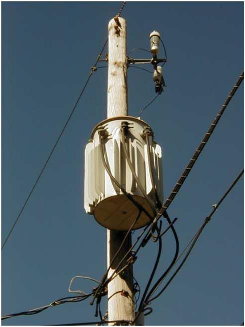
36 Inductor Applications 36

37 UI Core Inductor MEC 37
38 Reluctances 38

39 Reluctances 39
40 Reduced Equivalent Circuit 40
41 Example Let us consider a UI core inductor with the following parameters: w i = 25.1 mm, w b = w e = 25.3 mm, w s = 51.2 mm, d s = 31.7 mm, l c = mm, g =1.00 mm, w w = 38.1 mm, and d w = 31.7 mm. The winding is composed of 35 turns. Suppose the magnetic core material has a constant relative permeability of 7700, and that a current of 25.0 A is flowing. Compute the flux through the magnetic circuit and the flux density in the I-core. 41
42 Example 42
43 Example 43
44 Solving the Nonlinear Case R ( Φ ) = R ( Φ ) + R ( Φ ) + 2 R ( Φ ) + 2R eq ic buc luc g Φ = R eq Ni ( Φ) 44
45 Translation of Magnetic Circuits to Electric Circuits: Flux Linkage and Inductance 45
46 Flux Linkage λ = N Φ x x x 46
47 Inductance L x, abs = λ i x x i, λ x1 x1 L inc = λx i x i x1 47
48 Example Suppose λ = 0.05(1 e 0.2i ) i Find the absolute and incremental inductance at 5 A 48
49 Computing Inductance Φ x N x i x + - R x 49
50 Computing Inductance 50
51 Nonlinear Flux Linkage Vs. Current 51
52 Nonlinear Flux Linkage Vs. Current 52
53 Nonlinear Flux Linkage Vs. Current % Computation of lambda-i curve % for UI core inductor % using a simple but nonlinear MEC % % S.D. Sudhoff for ECE321 % January 13, 2012 % clear work space clear all close all g=1*mm; % air gap (m) N=100; % number of turns mu0=4e-7*pi; % perm of free space (H/m) Bsat=1.3; % sat flux density (T) mur=1500; % init rel permeability Am=w*d; % mag cross section (m^2) % start with flux linkage lambda=linspace(0,0.08,1000); % assign parameters cm = 1e-2; % a centimeter mm = 1e-3; % a millimiter w=1*cm; % core width (m) ws=5*cm; % slot width (m) ds=2*cm; % slot depth (m) d=5*cm; % depth (m) % find flux and B and mu phi=lambda/n; B=phi/(w*d); mu=mu0*(mur-1)./(exp(10*(b-bsat)).^2+1)+mu0; 53
54 Nonlinear Flux Linkage Vs. Current % Assign reluctances; Ric=(ws+w)./(Am*mu); Rbuc=(ws+w)./(Am*mu); Rg=g/(Am*mu0); Rluc=(ds+w/2)./(Am*mu); % compute effective reluctances Reff=Ric+Rbuc+2*Rluc+2*Rg; % compute MMF and current F=Reff.*phi; i=f/n; % find lambda-i characteristic figure(1) plot(i,lambda); xlabel('i, A'); ylabel('\lambda, Vs'); grid on; % show B-H characteristic H=B./mu; figure(2) plot(h,b) xlabel('h, A/m'); ylabel('b, T'); grid on; 54
55 Nonlinear Flux Linkage Vs. Current 55
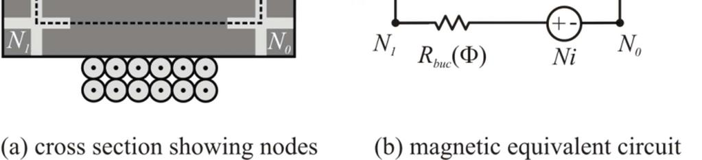
56 Hardware Example Our MEC
57 Non-Idealities: Fringing and Leakage Flux Log10 Energy Density J/m y,m x,m 57
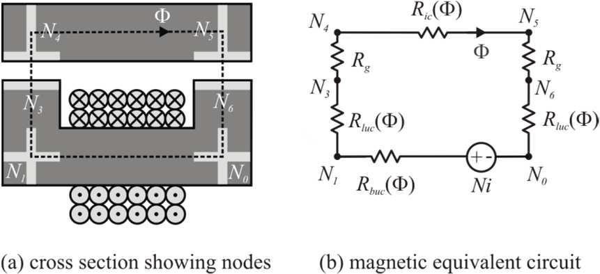
58 Our MEC With Leakage and Fringing 58
59 Faraday s Law Faraday s Law, voltage equation for winding vx = rxix dλ + x dt If inductance is constant λ x = L x i x Combining above yields vx = rxix + di L x x dt 59
60 Energy Stored in a Magnetically Linear Inductor We can show Proof E = x 1 2 L x i 2 x 60
61 Mutual Inductance 61
62 Mutual Inductance 62
63 Case Study: Lets Design a UI Core Inductor 63
64 Architecture Depth into page = d Node 8 Node 7 Node 1 Node 2 w Node 3 g Node 4 N Turns d s w Node 6 Node 5 w ws w 64
65 Design Requirements Current Level: 40 A Inductance: 5 mh Packing Factor: 0.7 Slot Shape η dw : 1 Maximum Resistance: 0.1Ω 65
66 Information Cost of Ferrite: 230 k$/m 3 Density of Ferrite: 4740 Kg/m 3 Saturation Flux Density: 0.5 T Cost of Copper: 556 $/m 3 Density of Copper: 8960 Kg/m 3 Resistivity of Copper: 1.7e-8 Ωm 66
67 Step 1: Design Variables Depth into page = d Node 8 Node 7 Node 1 Node 2 w Node 3 g Node 4 N Turns d s w Node 6 Node 5 w ws w 67
68 Step 2: Design Constraints Constraint 1: Flux Density 68
69 Step 2: Design Constraints Constraint 2: Inductance 69
70 Step 2: Design Constraints Constraint 3: Slot Shape 70
71 Step 2: Design Constraints Constraint 4: Packing Factor 71
72 Step 2: Design Constraints Constraint 5: Resistance 72
73 Step 2: Design Constraints 73
74 Approach (1/6) 74
75 Approach (2/6) 75
76 Approach (3/6) 76
77 Approach (4/6) 77
78 Approach (5/6) 78
79 Approach (6/6) 79
80 Design Metrics Magnetic Material Volume Depth into page = d Node 8 Node 7 Node 1 Node 2 w Node 3 g Node 4 N Turns d s w Node 6 Node 5 w ws w 80
81 Design Metrics Wire Volume 81
82 Design Metrics Circumscribing Box Depth into page = d Node 8 Node 7 Node 1 Node 2 w Node 3 g Node 4 N Turns d s w Node 6 Node 5 w ws w 82
83 Design Metrics Material Cost Mass 83
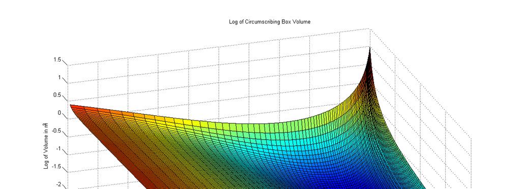
84 Circumscribing Box Volume 84

85 Material Cost 85
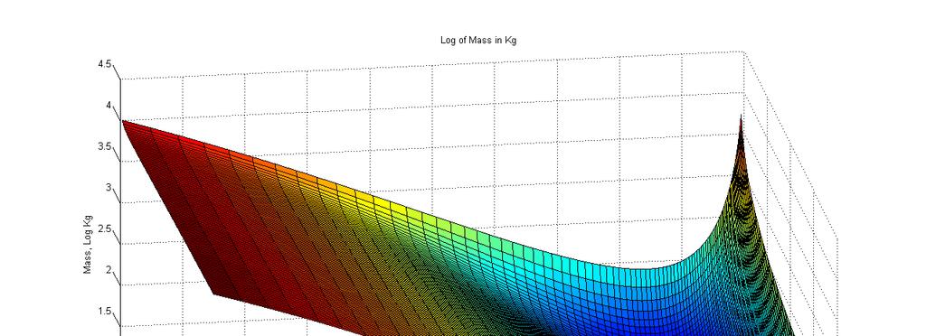
86 Mass 86
87 Least Cost Design N = 260 Turns d = cm g = mm w = cm a w = (mm)^2 d s = 8.94 cm w s = 8.94 cm V mm = m^3 V cu = m^3 V bx = m^3 Cost = $ Mass = Kg 87
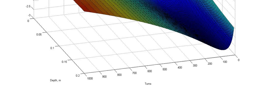
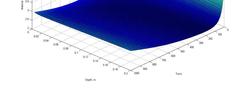
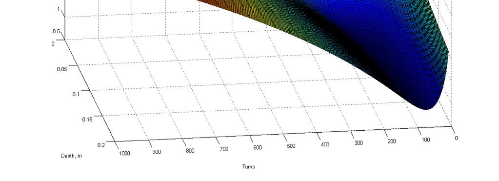
88 Loss and Mass 88
89 Design Criticisms 89

90 Manual Design Approach Flux Density B/m Analysis y,m 0 Design Equations Numerical Analysis Design Revisions x,m Final Design 90


91 Formal Design Optimization Evolutionary Environment Detailed Analysis Fitness Function 91


92 Another Design Trade-Off 92
93 Lunar Rover Propulsion Drive Pareto-Optimal Front 93
R. W. Erickson. Department of Electrical, Computer, and Energy Engineering University of Colorado, Boulder
 R. W. Erickson Department of Electrical, Computer, and Energy Engineering University of Colorado, Boulder Part III. Magnetics 13 Basic Magnetics Theory 14 Inductor Design 15 Transformer Design 1 Chapter
MAGNETISM. Magnetism. Magnetism is a result of electrons spinning on their own axis around the nucleus (Figure 18). Basic Electrical Theory
. Basic Electrical Theory") Basic Electrical Theory Certain metals and metallic oxides have the ability to attract other metals. This property is called magnetism, and the materials which have this property are called magnets. Some
Basic Electrical Theory Certain metals and metallic oxides have the ability to attract other metals. This property is called magnetism, and the materials which have this property are called magnets. Some
Chapter 1 Magnetic Circuits
 Principles of Electric Machines and Power Electronics Third Edition P. C. Sen Chapter 1 Magnetic Circuits Chapter 1: Main contents i-h relation, B-H relation Magnetic circuit and analysis Property of magnetic
Lecture 24. April 5 th, Magnetic Circuits & Inductance
 Lecture 24 April 5 th, 2005 Magnetic Circuits & Inductance Reading: Boylestad s Circuit Analysis, 3 rd Canadian Edition Chapter 11.1-11.5, Pages 331-338 Chapter 12.1-12.4, Pages 341-349 Chapter 12.7-12.9,
Magnetic Quantities. Magnetic fields are described by drawing flux lines that represent the magnetic field.
 Chapter 7 Magnetic fields are described by drawing flux lines that represent the magnetic field. Where lines are close together, the flux density is higher. Where lines are further apart, the flux density
Lecture Notes ELEC A6
 Lecture Notes ELEC A6 Dr. Ramadan El-Shatshat Magnetic circuit 9/27/2006 Elec-A6 - Electromagnetic Energy Conversion 1 Magnetic Field Concepts Magnetic Fields: Magnetic fields are the fundamental mechanism
The initial magnetization curve shows the magnetic flux density that would result when an increasing magnetic field is applied to an initially
 MAGNETIC CIRCUITS The study of magnetic circuits is important in the study of energy systems since the operation of key components such as transformers and rotating machines (DC machines, induction machines,
Magnetism & Electromagnetism
 Magnetism & Electromagnetism By: Dr Rosemizi Abd Rahim Click here to watch the magnetism and electromagnetism animation video http://rmz4567.blogspot.my/2013/02/electrical-engineering.html 1 Learning Outcomes
Electromagnetic Induction & Inductors
 Electromagnetic Induction & Inductors 1 Revision of Electromagnetic Induction and Inductors (Much of this material has come from Electrical & Electronic Principles & Technology by John Bird) Magnetic Field
Chapter 15 Magnetic Circuits and Transformers
 Chapter 15 Magnetic Circuits and Transformers Chapter 15 Magnetic Circuits and Transformers 1. Understand magnetic fields and their interactio with moving charges. 2. Use the right-hand rule to determine
Chapter 7. Chapter 7. Electric Circuits Fundamentals - Floyd. Copyright 2007 Prentice-Hall
 Chapter 7 Magnetic Quantities Magnetic fields are described by drawing flux lines that represent the magnetic field. Where lines are close together, the flux density is higher. Where lines are further
Chapter 14: Inductor design
 Chapter 14 Inductor Design 14.1 Filter inductor design constraints 14.2 A step-by-step design procedure 14.3 Multiple-winding magnetics design using the K g method 14.4 Examples 14.5 Summary of key points
Chapter 2 Basics of Electricity and Magnetism
 Chapter 2 Basics of Electricity and Magnetism My direct path to the special theory of relativity was mainly determined by the conviction that the electromotive force induced in a conductor moving in a
Part III. Magnetics. Chapter 13: Basic Magnetics Theory. Chapter 13 Basic Magnetics Theory
 Part III. Magnetics 3 Basic Magnetics Theory Inductor Design 5 Transformer Design Chapter 3 Basic Magnetics Theory 3. Review of Basic Magnetics 3.. Basic relationships 3..2 Magnetic circuits 3.2 Transformer
SYLLABUS(EE-205-F) SECTION-B
 SECTION-B") SYLLABUS(EE-205-F) SECTION-A MAGNETIC CIRCUITS AND INDUCTION: Magnetic Circuits, Magnetic Materials and their properties, static and dynamic emfs and dforce on current carrying conductor, AC operation
SYLLABUS(EE-205-F) SECTION-A MAGNETIC CIRCUITS AND INDUCTION: Magnetic Circuits, Magnetic Materials and their properties, static and dynamic emfs and dforce on current carrying conductor, AC operation
Switched Mode Power Conversion Prof. L. Umanand Department of Electronics System Engineering Indian Institute of Science, Bangalore
 Switched Mode Power Conversion Prof. L. Umanand Department of Electronics System Engineering Indian Institute of Science, Bangalore Lecture - 39 Magnetic Design Good day to all of you. Today, we shall
Course no. 4. The Theory of Electromagnetic Field
 Cose no. 4 The Theory of Electromagnetic Field Technical University of Cluj-Napoca http://www.et.utcluj.ro/cs_electromagnetics2006_ac.htm http://www.et.utcluj.ro/~lcret March 19-2009 Chapter 3 Magnetostatics
R. W. Erickson. Department of Electrical, Computer, and Energy Engineering University of Colorado, Boulder
 R. W. Erickson Department of Electrical, Computer, and Energy Engineering University of Colorado, Boulder Chapter 14 Inductor Design 14.1 Filter inductor design constraints 14.2 A step-by-step design procedure
EDEXCEL NATIONAL CERTIFICATE/DIPLOMA UNIT 5 - ELECTRICAL AND ELECTRONIC PRINCIPLES NQF LEVEL 3. OUTCOME 3 - MAGNETISM and INDUCTION
 EDEXCEL NATIONAL CERTIFICATE/DIPLOMA UNIT 5 - ELECTRICAL AND ELECTRONIC PRINCIPLES NQF LEVEL 3 OUTCOME 3 - MAGNETISM and INDUCTION 3 Understand the principles and properties of magnetism Magnetic field:
ENGINEERING COUNCIL CERTIFICATE LEVEL ENGINEERING SCIENCE C103 TUTORIAL 16 - INDUCTANCE
 ENGINEERING COUNCIL CERTIFICATE LEVEL ENGINEERING SCIENCE C103 TUTORIAL 16 - INDUCTANCE On completion of this tutorial you should be able to do the following. Explain inductance and inductors. Explain
Magnetic Fields
 Magnetic circuits introduction Becomes aware of the similarities between the analysis of magnetic circuits and electric circuits. Develop a clear understanding of the important parameters of a magnetic
MAGNETIC CIRCUITS. Magnetic Circuits
 Basic Electrical Theory What is a magnetic circuit? To better understand magnetic circuits, a basic understanding of the physical qualities of magnetic circuits will be necessary. EO 1.8 EO 1.9 EO 1.10
Notes on Mutual Inductance and Transformers J. McCalley
 ωωωωωωωω ωωωωωωωω otes on Mutual nductance and Transformers J. McCalley.0 Use of Transformers Transformers are one of the most common electrical devices. Perhaps the most familiar application today is
Electrical Eng. fundamental Lecture 1
 Electrical Eng. fundamental Lecture 1 Contact details: h-elhelw@staffs.ac.uk Introduction Electrical systems pervade our lives; they are found in home, school, workplaces, factories,
Tutorial Sheet IV. Fig. IV_2.
 Tutorial Sheet IV 1. Two identical inductors 1 H each are connected in series as shown. Deduce the combined inductance. If a third and then a fourth are similarly connected in series with this combined
FB-DC6 Electric Circuits: Magnetism and Electromagnetism
 CREST Foundation Electrical Engineering: DC Electric Circuits Kuphaldt FB-DC6 Electric Circuits: Magnetism and Electromagnetism Contents 1. Electromagnetism 2. Magnetic units of measurement 3. Permeability
Tutorial Sheet Fig. Q1
 Tutorial Sheet - 04 1. The magnetic circuit shown in Fig. Q1 has dimensions A c = A g = 9 cm 2, g = 0.050 cm, l c = 30 cm, and N = 500 turns. Assume the value of the relative permeability,µ r = 70,000
Basic Electronics. Introductory Lecture Course for. Technology and Instrumentation in Particle Physics Chicago, Illinois June 9-14, 2011
 Basic Electronics Introductory Lecture Course for Technology and Instrumentation in Particle Physics 2011 Chicago, Illinois June 9-14, 2011 Presented By Gary Drake Argonne National Laboratory drake@anl.gov
Switched Mode Power Conversion
 Inductors Devices for Efficient Power Conversion Switches Inductors Transformers Capacitors Inductors Inductors Store Energy Inductors Store Energy in a Magnetic Field In Power Converters Energy Storage
A/m Air Gap Anisotropic BH Curve cgs Coercivity Curie Temperature Demagnetization curve Eddy Current Ferromagnetic Flux
 Magnetic Definitions A/m Ampere turns per meter = The MKS unit of magnetic field strength (1 A/m = 4π/1000 Oersteds 0.01257 Oersteds) Air Gap - A nonmagnetic discontinuity in a magnetic circuit. Anisotropic
Revision Guide for Chapter 15
 Revision Guide for Chapter 15 Contents Revision Checklist Revision otes Transformer...4 Electromagnetic induction...4 Lenz's law...5 Generator...6 Electric motor...7 Magnetic field...9 Magnetic flux...
Part 4: Electromagnetism. 4.1: Induction. A. Faraday's Law. The magnetic flux through a loop of wire is
 1 Part 4: Electromagnetism 4.1: Induction A. Faraday's Law The magnetic flux through a loop of wire is Φ = BA cos θ B A B = magnetic field penetrating loop [T] A = area of loop [m 2 ] = angle between field
ROEVER COLLEGE OF ENGINEERING & TECHNOLOGY ELAMBALUR, PERAMBALUR DEPARTMENT OF ELECTRICAL AND ELECTRONICS ENGINEERING ELECTRICAL MACHINES I
 ROEVER COLLEGE OF ENGINEERING & TECHNOLOGY ELAMBALUR, PERAMBALUR-621220 DEPARTMENT OF ELECTRICAL AND ELECTRONICS ENGINEERING ELECTRICAL MACHINES I Unit I Introduction 1. What are the three basic types
Magnetic Force on a Moving Charge
 Magnetic Force on a Moving Charge Electric charges moving in a magnetic field experience a force due to the magnetic field. Given a charge Q moving with velocity u in a magnetic flux density B, the vector
Electric vs Magnetic Comparison
 5. MAGNETOSTATICS Electric vs Magnetic Comparison J=σE Most dielectrics µ = µo excluding ferromagnetic materials Gauss s Law E field is conservative Gauss s law (integral) Conservative E field Electric
Electromagnetism. Topics Covered in Chapter 14:
 Chapter 14 Electromagnetism Topics Covered in Chapter 14: 14-1: Ampere-turns of Magnetomotive Force (mmf) 14-2: Field Intensity (H) 14-3: B-H Magnetization Curve 14-4: Magnetic Hysteresis 14-5: Magnetic
MAGNETIC CIRCUITS, MOTOR AND GENERATOR ACTION
 Topic 3 MAGNETIC CIRCUITS, MOTOR AND GENERATOR ACTION Magnetic Flux SI unit, Webers (Wb) ϕ Flows from North to South Pole 1 Magnetic Flux Density Measure of Flux/Area SI units, Wb/m 2 = Tesla, B Think
Chapter 13 Principles of Electromechanics
 Chapter 13 Principles of Electromechanics Jaesung Jang Electrostatics B-H Magnetization Curves & Magnetic Hysteresis 1 Electrostatics & Magnetic Flux The force on a stationary charge q in an electric field
Revision Guide for Chapter 15
 Revision Guide for Chapter 15 Contents tudent s Checklist Revision otes Transformer... 4 Electromagnetic induction... 4 Generator... 5 Electric motor... 6 Magnetic field... 8 Magnetic flux... 9 Force on
CHAPTER 6. Inductance, Capacitance, and Mutual Inductance
 CHAPTER 6 Inductance, Capacitance, and Mutual Inductance 6.1 The Inductor Inductance is symbolized by the letter L, is measured in henrys (H), and is represented graphically as a coiled wire. The inductor
Induction and Inductance
 Induction and Inductance Key Contents Faraday s law: induced emf Induction and energy transfer Inductors and inductance RL circuits Magnetic energy density The First Experiment 1. A current appears only
9-3 Inductance. * We likewise can have self inductance, were a timevarying current in a circuit induces an emf voltage within that same circuit!
 /3/004 section 9_3 Inductance / 9-3 Inductance Reading Assignment: pp. 90-86 * A transformer is an example of mutual inductance, where a time-varying current in one circuit (i.e., the primary) induces
The magnetic circuits and fields in materials
 The magnetic circuits and fields in materials Lecture 14 1 Linear current above a magnetic block In this example, assume a current density J above an infinite slab of linear magnetic material, with permeability,
Texas A & M University Department of Mechanical Engineering MEEN 364 Dynamic Systems and Controls Dr. Alexander G. Parlos
 Texas A & M University Department of Mechanical Engineering MEEN 364 Dynamic Systems and Controls Dr. Alexander G. Parlos Lecture 5: Electrical and Electromagnetic System Components The objective of this
MAGNETIC FIELDS & UNIFORM PLANE WAVES
 MAGNETIC FIELDS & UNIFORM PLANE WAVES Name Section Multiple Choice 1. (8 Pts) 2. (8 Pts) 3. (8 Pts) 4. (8 Pts) 5. (8 Pts) Notes: 1. In the multiple choice questions, each question may have more than one
6.013 Lecture 11: Inductors and Transformers
 6.013 Lecture 11: Inductors and Transformers A. Inductors All circuits carry currents that necessarily produce magnetic fields and store magnetic energy. Thus every wire and circuit element generally has
Magnetic Materials. 1. General Information About Magnetism. Numan Akdoğan.
 Magnetic Materials 1. General Information About Magnetism Numan Akdoğan akdogan@gyte.edu.tr Gebze Institute of Technology Department of Physics Nanomagnetism and Spintronic Research Center (NASAM) Magnetic
Chapter 30. Induction and Inductance
 Chapter 30 Induction and Inductance 30.2: First Experiment: 1. A current appears only if there is relative motion between the loop and the magnet (one must move relative to the other); the current disappears
Ferromagnetism. In free space, the flux density and magnetizing field strength are related by the expression
 1 Ferromagnetism B In free space, the flux density and magnetizing field strength are related by the expression H B =µ 0 H µ 0 =4π x 10-7 H.m -1, the permeability of free space. 2 Ferromagnetism B H For
Transmission Lines and E. M. Waves Prof. R. K. Shevgaonkar Department of Electrical Engineering Indian Institute of Technology, Bombay
 Transmission Lines and E. M. Waves Prof. R. K. Shevgaonkar Department of Electrical Engineering Indian Institute of Technology, Bombay Lecture 18 Basic Laws of Electromagnetics We saw in the earlier lecture
Review of Basic Electrical and Magnetic Circuit Concepts EE
 Review of Basic Electrical and Magnetic Circuit Concepts EE 442-642 Sinusoidal Linear Circuits: Instantaneous voltage, current and power, rms values Average (real) power, reactive power, apparent power,
Mutual Inductance: This is the magnetic flux coupling of 2 coils where the current in one coil causes a voltage to be induced in the other coil.
 agnetically Coupled Circuits utual Inductance: This is the magnetic flux coupling of coils where the current in one coil causes a voltage to be induced in the other coil. st I d like to emphasize that
DHANALAKSHMI COLLEGE OF ENGINEERING DEPARTMENT OF EEE PART A. 1. Define mutual inductance and self inductance. (A/M-15)
") DHANALAKSHMI COLLEGE OF ENGINEERING DEPARTMENT OF EEE EE6302-ELECTROMAGNETIC THEORY UNIT 4 PART A 1. Define mutual inductance and self inductance. (A/M-15) Self inductance is the ration between the induced
DHANALAKSHMI COLLEGE OF ENGINEERING DEPARTMENT OF EEE EE6302-ELECTROMAGNETIC THEORY UNIT 4 PART A 1. Define mutual inductance and self inductance. (A/M-15) Self inductance is the ration between the induced
Outside the solenoid, the field lines are spread apart, and at any given distance from the axis, the field is weak.
 Applications of Ampere s Law continued. 2. Field of a solenoid. A solenoid can have many (thousands) of turns, and perhaps many layers of windings. The figure shows a simple solenoid with just a few windings
CHAPTER 2 MAGNETISM. 2.1 Magnetic materials
 CHAPTER 2 MAGNETISM Magnetism plays a crucial role in the development of memories for mass storage, and in sensors to name a few. Spintronics is an integration of the magnetic material with semiconductor
15.1 Transformer Design: Basic Constraints. Chapter 15: Transformer design. Chapter 15 Transformer Design
 Chapter 5 Transformer Design Some more advanced design issues, not considered in previous chapter: : n Inclusion of core loss Selection of operating flux density to optimize total loss Multiple winding
6.014 Lecture 11: Inductors and Transformers
 6.014 Lecture 11: Inductors and Transformers A. Inductors All circuits carry currents that necessarily produce magnetic fields and store magnetic energy. Thus every wire and circuit element generally has
Chapter 2: Fundamentals of Magnetism. 8/28/2003 Electromechanical Dynamics 1
 Chapter 2: Fundamentals of Magnetism 8/28/2003 Electromechanical Dynamics 1 Magnetic Field Intensity Whenever a magnetic flux, φ, exist in a conductor or component, it is due to the presence of a magnetic
LECTURE 5 PER-PHASE CIRCUITS AND MAGNETICS (1)
") ECE 330 POWER CIRCUITS AND ELECTROMECHANICS LECTURE 5 PER-PHASE CIRCUITS AND MAGNETICS (1) Aknowledgment-These handouts and leture notes given in lass are based on material from Prof. Peter Sauer s ECE
ECE 330 POWER CIRCUITS AND ELECTROMECHANICS LECTURE 5 PER-PHASE CIRCUITS AND MAGNETICS (1) Aknowledgment-These handouts and leture notes given in lass are based on material from Prof. Peter Sauer s ECE
Chapter 30. Induction and Inductance
 Chapter 30 Induction and Inductance 30.2: First Experiment: 1. A current appears only if there is relative motion between the loop and the magnet (one must move relative to the other); the current disappears
Mutual Inductance. The field lines flow from a + charge to a - change
 Capacitors Mutual Inductance Since electrical charges do exist, electric field lines have a starting point and an ending point. For example, if you have a + and a - change, the field lines would look something
Electromagnetic Field Theory Chapter 9: Time-varying EM Fields
 Electromagnetic Field Theory Chapter 9: Time-varying EM Fields Faraday s law of induction We have learned that a constant current induces magnetic field and a constant charge (or a voltage) makes an electric
SECOND ENGINEER REG III/2 MARINE ELECTRO-TECHNOLOGY. 1. Understands the physical construction and characteristics of basic components.
 SECOND ENGINEER REG III/ MARINE ELECTRO-TECHNOLOGY LIST OF TOPICS A B C D Electric and Electronic Components Electric Circuit Principles Electromagnetism Electrical Machines The expected learning outcome
Physics 2020 Exam 2 Constants and Formulae
 Physics 2020 Exam 2 Constants and Formulae Useful Constants k e = 8.99 10 9 N m 2 /C 2 c = 3.00 10 8 m/s ɛ = 8.85 10 12 C 2 /(N m 2 ) µ = 4π 10 7 T m/a e = 1.602 10 19 C h = 6.626 10 34 J s m p = 1.67
Lecture 30: WED 04 NOV
 Physics 2113 Jonathan Dowling Lecture 30: WED 04 NOV Induction and Inductance II Fender Stratocaster Solenoid Pickup F a r a d a y ' s E x p e r i m e n t s I n a s e r i e s o f e x p e r i m e n t s,
Suppose two uniform bars meet at an abrupt plane and there is a magnetic field induced by an extended core and coil structure off stage as in:
 Class Notes Week of 1/9 /3/017 ENGN1931F The magnetic structures that are central to the design of generators, transformers, motors, inductors, solenoids, etc. can be complex. We need a way to make approximate
Recap (1) Maxwell s Equations describe the electric field E and magnetic field B generated by stationary charge density ρ and current density J:
 Maxwell s Equations describe the electric field E and magnetic field B generated by stationary charge density ρ and current density J:") Class 13 : Induction Phenomenon of induction and Faraday s Law How does a generator and transformer work? Self- and mutual inductance Energy stored in B-field Recap (1) Maxwell s Equations describe the
Class 13 : Induction Phenomenon of induction and Faraday s Law How does a generator and transformer work? Self- and mutual inductance Energy stored in B-field Recap (1) Maxwell s Equations describe the
Capacitors. Charging a Capacitor. Charge and Capacitance. L05: Capacitors and Inductors
 L05: Capacitors and Inductors 50 Capacitors 51 Outline of the lecture: Capacitors and capacitance. Energy storage. Capacitance formula. Types of capacitors. Inductors and inductance. Inductance formula.
Definition Application of electrical machines Electromagnetism: review Analogies between electric and magnetic circuits Faraday s Law Electromagnetic
 Definition Application of electrical machines Electromagnetism: review Analogies between electric and magnetic circuits Faraday s Law Electromagnetic Force Motor action Generator action Types and parts
Section 8: Magnetic Components
 Section 8: Magnetic omponents Inductors and transformers used in power electronic converters operate at quite high frequency. The operating frequency is in khz to MHz. Magnetic transformer steel which
PHY481 - Lecture 29 Chapter 9 of PS, Chapters 6,7 of Griffiths
 PHY481 - Lecture 29 Chapter 9 of PS, Chapters 6,7 of Griffiths A. Energy stored in inductors and in magnetic fields An external voltage source must be used to set up a magnetic field in an inductor. The
COPYRIGHTED MATERIAL. Fundamentals of Magnetic Devices. 1.1 Introduction
 1 Fundamentals of Magnetic Devices 1.1 Introduction Many electronic circuits require the use of inductors and transformers [1] [47]. These are usually the largest, heaviest, and most expensive components
Basic Electrical Technology Prof. Dr. L. Umanand Department of Electrical Engineering Indian Institute of Science, Bangalore
 Basic Electrical Technology Prof. Dr. L. Umanand Department of Electrical Engineering Indian Institute of Science, Bangalore Lecture - 18 Transformer Basics Part - II Hello everybody, in the last session
Measurement And Testing. Handling And Storage. Quick Reference Specification Checklist
 Design Guide Contents Introduction Manufacturing Methods Modern Magnet Materials Coatings Units Of Measure Design Considerations Permanent Magnet Stability Physical Characteristics And Machining Of Permanent
6.013 Lecture 13: Reluctance and Permanent Magnet Motors; Photon Forces
 A. Overview 6.013 Lecture 13: Reluctance and Permanent Magnet Motors; Photon Forces Reluctance motors generally incorporate soft-iron rotors that are pulled toward magnetized poles. By switching the excitation
Physics 202, Lecture 14
 Physics 202, Lecture 14 Today s Topics Sources of the Magnetic Field (Ch. 30) Review: iot-savart Law, Ampere s Law Displacement Current: Ampere-Maxwell Law Magnetism in Matter Maxwell s Equations (prelude)
PHY331 Magnetism. Lecture 1
 PHY331 Magnetism Lecture 1 Overview Course syllabus / general information Quick revision of basic concepts Magnetization and susceptibility Using susceptibility to define magnetic materials Diamagnetic
Exam 3 Solutions. The induced EMF (magnitude) is given by Faraday s Law d dt dt The current is given by
 is given by Faraday s Law d dt dt The current is given by") PHY049 Spring 008 Prof. Darin Acosta Prof. Selman Hershfield April 9, 008. A metal rod is forced to move with constant velocity of 60 cm/s [or 90 cm/s] along two parallel metal rails, which are connected
PHY049 Spring 008 Prof. Darin Acosta Prof. Selman Hershfield April 9, 008. A metal rod is forced to move with constant velocity of 60 cm/s [or 90 cm/s] along two parallel metal rails, which are connected
Basic Electrical Engineering SYLLABUS. Total No. of Lecture Hrs. : 50 Exam Marks : 80
 SYLLABUS Subject Code: /25 No. of Lecture Hrs./ Week : 04 IA Marks : 20 Exam Hours : 03 Total No. of Lecture Hrs. : 50 Exam Marks : 80 Course objectives: Impart a basic knowledge of electrical quantities
KINGS COLLEGE OF ENGINEERING DEPARTMENT OF ELECTRONICS AND COMMUNICATION ENGINEERING QUESTION BANK
 KINGS COLLEGE OF ENGINEERING DEPARTMENT OF ELECTRONICS AND COMMUNICATION ENGINEERING QUESTION BANK SUB.NAME : ELECTROMAGNETIC FIELDS SUBJECT CODE : EC 2253 YEAR / SEMESTER : II / IV UNIT- I - STATIC ELECTRIC
Lecture 16.1 :! Final Exam Review, Part 2
 Lecture 16.1 :! Final Exam Review, Part 2 April 28, 2015 1 Announcements Online Evaluation e-mails should have been sent to you.! Please fill out the evaluation form. May 6 is deadline.! Remember that
Magnetic field creation (example of a problem)
") 1 Magnetic field creation (example of a problem) Three long, straight wires are parallel to each other and perpendicular to the plane of the paper. Their mutual location is shown in Figure below. The currents
1 Magnetic field creation (example of a problem) Three long, straight wires are parallel to each other and perpendicular to the plane of the paper. Their mutual location is shown in Figure below. The currents
ENGG4420 LECTURE 7. CHAPTER 1 BY RADU MURESAN Page 1. September :29 PM
 CHAPTER 1 BY RADU MURESAN Page 1 ENGG4420 LECTURE 7 September 21 10 2:29 PM MODELS OF ELECTRIC CIRCUITS Electric circuits contain sources of electric voltage and current and other electronic elements such
ELECTRIC MACHINE TORQUE PRODUCTION 101
 ELECTRIC MACHINE TORQUE PRODUCTION 101 Best Electric Machine, 014 INTRODUCTION: The following discussion will show that the symmetrical (or true dual-ported) transformer electric machine as only provided
/20 /20 /20 /60. Dr. Galeazzi PHY207 Test #3 November 20, I.D. number:
 Signature: Name: I.D. number: You must do ALL the problems Each problem is worth 0 points for a total of 60 points. TO GET CREDIT IN PROBLEMS AND 3 YOU MUST SHOW GOOD WORK. CHECK DISCUSSION SECTION ATTENDED:
MAGNETIC DIPOLES, HYSTERESIS AND CORE LOSES
 Power Quality For The Digital Age MAGNETIC DIPOLES, HYSTERESIS AND CORE LOSES A N E N V I R O N M E N T A L P O T E N T I A L S W H I T E P A P E R By Professor Edward Price Director of Research and Development
LINEAR ELECTRIC ACTUATORS AND GENERATORS
 LINEAR ELECTRIC ACTUATORS AND GENERATORS LINEAR ELECTRIC ACTUATORS AND GENERATORS I. Boldea Polytechnic Institute, Timisoara, Romania Syed A. Nasar University of Kentucky CAMBRIDGE UNIVERSITY PRESS CAMBRIDGE
Chapter 5: Electromagnetic Induction
 Chapter 5: Electromagnetic Induction 5.1 Magnetic Flux 5.1.1 Define and use magnetic flux Magnetic flux is defined as the scalar product between the magnetic flux density, B with the vector of the area,
R. W. Erickson. Department of Electrical, Computer, and Energy Engineering University of Colorado, Boulder
 R. W. Erickson Department of Electrical, Computer, and Energy Engineering University of Colorado, Boulder 15.3.2 Example 2 Multiple-Output Full-Bridge Buck Converter Q 1 D 1 Q 3 D 3 + T 1 : : n 2 D 5 i
Maxwell s Equations:
 Course Instructor Dr. Raymond C. Rumpf Office: A-337 Phone: (915) 747-6958 E-Mail: rcrumpf@utep.edu Maxwell s Equations: Physical Interpretation EE-3321 Electromagnetic Field Theory Outline Maxwell s Equations
Definitions of Terminology in Magnetics
 Definitions of Terminology in Magnetics Ag Area of the air gap, or the cross sectional area of the air gap perpendicular to the flux path, is the average cross sectional area of that portion of the air
Electro-Magneto-Mechanics
 Electro-Magneto-Mechanics Dr. Kevin Craig Professor of Mechanical Engineering Rensselaer Polytechnic Institute Electromechanics K. Craig 1 Learning Objectives Understand the basic principles of electricity
DOE FUNDAMENTALS HANDBOOK ELECTRICAL SCIENCE Volume 1 of 4
 DOE-HDBK-1011/1-92 JUNE 1992 DOE FUNDAMENTALS HANDBOOK ELECTRICAL SCIENCE Volume 1 of 4 U.S. Department of Energy Washington, D.C. 20585 FSC-6910 Distribution Statement A. Approved for public release;
Magnetic Energy Domain Magnetic Capacitance Magnetic Resistance Magnetic Domain Example: Inductor with Flux Return Magnetic Circuit
 Michael David Bryant 9/8/07 Electromechanics, sensors & actuators Magnetic Energy Domain Magnetic Capacitance Magnetic Resistance Magnetic Domain Example: Inductor with Flux Return Magnetic Circuit Example:
1 CHAPTER 12 PROPERTIES OF MAGNETIC MATERIALS
 1 CHAPTER 12 PROPERTIES OF MAGNETIC MATERIALS 12.1 Introduction This chapter is likely to be a short one, not least because it is a subject in which my own knowledge is, to put it charitably, a little
Lecture 10 Induction and Inductance Ch. 30
 Lecture 10 Induction and Inductance Ch. 30 Cartoon - Faraday Induction Opening Demo - Thrust bar magnet through coil and measure the current Topics Faraday s Law Lenz s Law Motional Emf Eddy Currents LR
Chapter 30 Inductance
 Chapter 30 Inductance In this chapter we investigate the properties of an inductor in a circuit. There are two kinds of inductance mutual inductance and self-inductance. An inductor is formed by taken
Gravity Electromagnetism Weak Strong
 19. Magnetism 19.1. Magnets 19.1.1. Considering the typical bar magnet we can investigate the notion of poles and how they apply to magnets. 19.1.1.1. Every magnet has two distinct poles. 19.1.1.1.1. N
Electromagnetic Induction
 Chapter 29 Electromagnetic Induction PowerPoint Lectures for University Physics, 14th Edition Hugh D. Young and Roger A. Freedman Lectures by Jason Harlow Learning Goals for Chapter 29 Looking forward
ELECTRICALMACHINES-I QUESTUION BANK
 ELECTRICALMACHINES-I QUESTUION BANK UNIT-I INTRODUCTION OF MAGNETIC MATERIAL PART A 1. What are the three basic rotating Electric machines? 2. Name the three materials used in machine manufacture. 3. What