Electrical Eng. fundamental Lecture 1
|
|
|
- Trevor Malone
- 5 years ago
- Views:
Transcription
1 Electrical Eng. fundamental Lecture 1 <Dr Hadi El-Helw> Contact details: h-elhelw@staffs.ac.uk
2 Introduction Electrical systems pervade our lives; they are found in home, school, workplaces, factories, and transportation vehicles-everywhere. A circuit model is used to connect our visualization to our analysis of a physical system. The challenge is to develop models that will predict the physical behaviour of real components accurately and result in mathematical equations that can be solved.
3 Basic Electrical Quantities Basic quantities: current, voltage and power. Electric current: Electric current in a wire is defined as the net amount of charge that passes through the wire per unit time, and is measured in amperes (A). where i dq dt i = current in amperes q = charge in coulombs t = time in sec. 1 Ampere = 1 Coulomb per second (C/s) Current in circuits physically realized by movement of electrons. Direction of current must be specified by an arrow.
4 By convention, current direction defined as flow of positive charge. Note that positive charge is not flowing physically. Electrons have negative charge. They move in the opposite direction of current electron motion positive current direction In general, current can be an arbitrary function of time. Constant current is called direct current (DC). Current that can be represented as a sinusoidal function of time (or in some contexts a sum of sinusoids) is called alternating current (AC).
5 Voltage Voltage is the energy absorbed or expended as a unit charge moves from one point to the other. Analogous to pressure in hydraulic system. Sometimes called potential difference. Can be created by a separation of charge. Is a measure of the potential between two points. Voltage pushes charge in one direction.
6 We use polarity (+ and on batteries) to indicates which direction the charge is being pushed Voltage is the energy required to move a unit charge through an element, measured in volts (V) v d dq where v = voltage in volts ω = energy in Joules q = charge in coulombs i + v - A Circuit Element B

7 Voltage ~ Pressure Electric Current ~ Water Current Sponge ~ Resistance
8 Electrical Power Time rate of expending or absorbing energy and is measured by Watts. p p d dt d dq dq dt vi where p = power in watts ω = energy in Joules t = time in seconds q = charge in coulombs i = current in apperes v = voltage in volts By convention Circuit elements that absorb power have a positive value of p. Circuit elements that produce power have a negative value of p.
9 Active elements Elements of electrical circuits Active elements are the elements that can generate energy or power, such as voltage and current sources. Ideally, a voltage source produces V s volts regardless of the current absorbed or produced by the connected device. Ideally, a current source produces I s amps regardless of the current in the connected device. In a particular circuit, there can be active elements that absorb power for example, a battery being charged.
10 Passive elements passive elements are the elements that can not generate energy, such as resistors, capacitors and inductors. resistors The ability of a material to resist (impede, obstruct) the flow charge is called its resistivity. It is represented by the letter R. A resistor is a circuit element that dissipates electrical energy (usually as heat) Real-world devices that are modeled by resistors: incandescent light bulbs, heating elements, long wires Resistance is measured in Ohms (Ω) Resistor is indicated by the symbol
11 Resistance of a wire depends on some factors like as length (L), crosssectional area (A) and resistivity of material (ρ). R L A Where ρ resistivity in Ω.m L length in m A cross-section area in m 2 The conductance (G) of a pure resistor is the reciprocal of its resistance. The unit of conductance is the siemens (S) or mho ( ). G 1 R Ω
12 Ohm s Law Ohm's law states that the current through a conductor between two points is directly proportional to the potential difference or voltage across the two points, and inversely proportional to the resistance between them. The mathematical equation that describes this relationship is: i v R where v is the potential difference measured across the resistance in units of volts; i is the current through the resistance in units of amperes and R is the resistance of the conductor in units of ohms.
13 Resistors in Series Two elements are in series if the current that flows through one must also flow through the other. R 1 R 2 Series If we wish to replace the two series resistors with a single equivalent resistor whose voltage-current relationship is the same, the equivalent resistor has a value given by R eq R 1 R 2
14 For N resistors in series, the equivalent resistor has a value given by: R 1 R 2 R eq R 3 R R R R eq R N
15 Consider two resistors in series with a voltage v across them: v 1 v R R R v v R R R v v R 1 R v i Voltage division:
16 Resistors in Parallel When the terminals of two or more circuit elements are connected to the same two nodes, the circuit elements are said to be in parallel. If we wish to replace the two parallel resistors with a single equivalent resistor whose voltage-current relationship is the same, the equivalent resistor has a value given by R 1 R 2 R eq R eq R1 R2 R R 1 2
17 For N resistors in parallel, the equivalent resistor has a value given by R R 2 R N R eq 1 1 R 1 R 1 R 1 R 1 eq R N
18 Consider two resistors in parallel with a voltage v across them: i Current division: + v - i 1 i 2 R 1 R 2 i 1 i 2 i i R 1 R R 1 2 R R 1 2 R 2
19 Electrical Eng. Fundamental Lecture 2 <Dr Hadi El-Helw> Contact details: h-elhelw@staffs.ac.uk

20 KCL and KVL Kirchhoff s Current Law (KCL) and Kirchhoff s Voltage Law (KVL) are the fundamental laws of circuit analysis. Gustav Kirchoff was an 18th century German mathematician
21 KCL The sum of all currents entering a node is zero, or The sum of currents entering a node is equal to sum of currents leaving a node. i 1 i 5 i 2 i 4 n j1 i j i 3 0 i i i i i 0 or i1 i2 i4 i3 i A node is a point where two or more circuit elements are connected together.
22 i 1 node i 2 i 3 i 1 flows into the node i 2 flows out of the node i 3 flows out of the node i 1 = i 2 + i 3 This equation can also be written in the following form: i 1 - i 2 - i 3 =0
23 Example How much are the currents i 1 and i 2? i 1 10 ma 4 ma 3 ma i 2 node + _ 4 ma + 3 ma + 7 ma = 14 ma i 2 = 10 ma 3 ma = 7 ma i 1 = 10 ma + 4 ma = 14 ma
24 KVL Kirchhoff s voltage law tells us how to handle voltages in an electric circuit. Kirchhoff s voltage law basically states that the algebraic sum of the voltages around any closed path (electric circuit) equal zero. n j1 v j Arrows are sometimes used to represent voltage differences; they point from low to high voltage. i i + v - 0 v
25 i + v 2 + v 1 +_ + v 3 + v 4 v 3 = v 4 v 1 + v 2 + v 3 = 0 v 1 + v 2 + v 4 = 0 or or v 1 = v 2 + v 3 v 1 = v 2 + v 4
26 Example If v 1 = 10 V and v 5 = 2 V, what are v 2, v 3, and v 4? + v 3 + v 1 = 10 V + _ + v 2 + v 4 + v 5 = 2 V v 2 = 10 V v 3 = 10 V 2 V = 8 V v 4 = 2 V
27 Example: The voltage v 1 and v 2 in the circuit shown are V and V respectively. Find the power supplied by each voltage source. Show that the total power supplied equals the total power dissipated in the resistors
28 Example: Find v 0 in the circuit shown.
29 Example: The current in the 12Ω resistor in the circuit shown is 1 A, find v g.
30 Electrical Eng. Fundamental Lecture 3 <Dr Hadi El-Helw> Contact details: h-elhelw@staffs.ac.uk
31 I i i i i i i i i i 0 ) ( v R R i i R R i 0 ) ( v R i R i R R i R i R i R i Node b Node c Node e Applying KCL at nodes b, c, and g Applying KVL
32 Example Find i 1, i 2, and i 3 Solution Applying KCL at node a i i i3 Applying KVL in the red loop i i i Applying KVL in the blue loop i 2 3 i i i i
33 Substituting from equation 1 in equation ( i i 2 2 i 3 ) i 3 3 i Solving equation 3 and 4 simultaneously i i mA 7.65mA Substituting in equation 1 i mA
34 The Node voltage method The Mesh current method Source transformation Superposition theorem
35 The Node voltage method 1-Determine the number of nodes within the network 2-Select a node as the reference node. Assign voltages v 1, v 2,,,, v n-1, to the remaining n 1 nodes. The voltages are referenced w.r.t. the reference node.
36 3- Apply KCL at each node except the reference, assume that all unknown currents leave the node for each application of KCL 4-Use Ohm s law to express the branch currents in terms of node voltage R v v R v R E v i i i i i o i
37 ii io 0 i4 i5 I v2v1 v2 R R 3 4 I 0 4- Solve the resulting simultaneous equations to obtain the unknown node voltages.
38 Example: Use the node-voltage method to find v o in the circuit shown
39 Example: Use the node-voltage method to find v 1 and v 2 in the circuit shown
40 Electrical Eng. Fundamental Lecture 4 <Dr Hadi El-Helw> Contact details: h-elhelw@staffs.ac.uk
41 Example: Use the node-voltage method to find the branch currents i a through i e in the circuit shown below.
42 Example: Use the node-voltage method to find the branch currents i 1 through i 3 in the circuit shown below.
43 The super node when a voltage source is connected between two non-reference nodes. Problem: The current through the voltage source cannot be written as function of its two terminal voltages!
 are enclosed in the supernode, two equations are needed for each supernode: KCL at supernode gives one equation( Write the")
44 Solution: Form a supernode which is formed by enclosing the voltage source and any elements in parallel with it in a closed boundary. Since there are two nodes (two terminals of the voltage source) are enclosed in the supernode, two equations are needed for each supernode: KCL at supernode gives one equation( Write the standard node equations for the supernode) v1 2 2 v
45 The other equation is the relationship between the voltages of the two nodes enclosed in the supernode v 2 v1 2
46 Example: Use the node-voltage method to find v and i in the circuit shown below.
47 Electrical Eng. Fundamental Lecture 5 <Dr Hadi El-Helw> Contact details: h-elhelw@staffs.ac.uk
48 Mesh Analysis 1-Assign a distinct current in the clockwise direction to each independent closed loop (mesh) of the circuit. It is not absolutely necessary to choose the clockwise direction for each loop current. However, it eliminates the need to have to choose a direction for each application. Any direction can be chosen for each loop current with no loss in accuracy as long as the remaining steps are followed properly. Note:A mesh is a loop which does not contain any other loops within it. 2- Indicate the polarities within each loop for each resistance as determined by the assumed direction of loop current for that loop.
49 3- Apply KVL around each closed loop in the clockwise direction. Again, clockwise direction was chosen to establish uniformity and prepare us for the format approach to follow: a- If an resistance has two or more assumed currents through it, the total current through the resistance is the assumed current of the loop in which KVL is being applied, plus the assumed currents of the other loops passing through in the same direction, minus the assumed currents passing through in the opposite direction b-the polarity of a voltage source is unaffected by the direction of the assigned loop currents. 4- Solve the resulting simultaneous linear equations for the assumed loop currents
50 Mesh 1 E ( ) 1 i1r1 R2 i1 i2 0 Mesh 2 R2 ( i2 i1 ) i2r3 E2 0
51 Example Use the mesh-current method to find the branch currents i a, i b, i c in the circuit shown in the figure below
52 Example Use the mesh-current method to find how much power the 4-A current source delivers to the circuit shown in the figure below
53 Supermesh: when a current source exists between two meshes Procedure: 1. Open the current source. That is form a single mesh for the two mesh sharing the current source.
54 2. Write the constraint equation for the currents (Apply KCL). i 2 i Write the standard mesh equation for the supermesh (Apply KVL). i1 6 i2 (10 4) 20
55 Example Use the mesh-current method to find the current i 1 in the circuit shown in the figure below
56 Electrical Eng. Fundamental Lecture 6 <Dr Hadi El-Helw> Contact details: h-elhelw@staffs.ac.uk
57 Source Transformation Circuit 1 Circuit 2 A source transformation allows us to replace a voltage source in series with a resistance by a current source in parallel with the same resistance, or vice versa
58 Circuit 1 Circuit 2 Connect the same load resistor R L across terminal a-b in both circuits. If circuits 1 and 2 are equivalent i 1 = i 2 & v 1 = v 2 L s s eq s R R V R V i 1 L P p s R R R I i 2 (use the current divider role) L p p s L s s R R R I R R V i i 2 1 If we choose R p =R s V s =I s R p =I s R s
59 Therefore V s I s R s R s R p
60 Reduction of sources
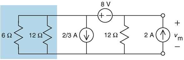
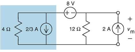
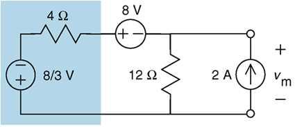
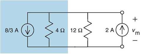
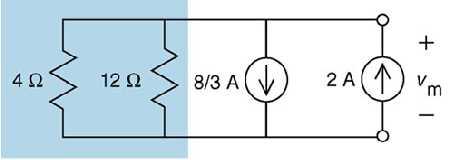
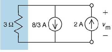
61 Example: Use concept of source transformation to find the voltage V m in the circuit shown in the figure below
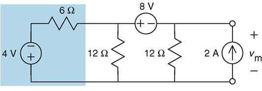
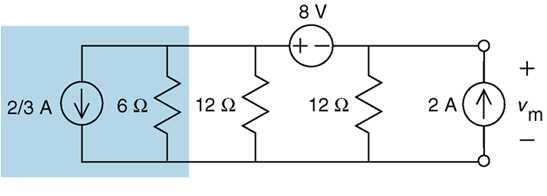
62 Solution

63
64
65
66
67 8 V m ( 2 ) 3 2V 3
68 Example: Use a series of source transformations to find the current i o in the circuit shown.
69 Example: Use a series of source transformations to find the current i o in the circuit shown.
70 Electrical Eng. Fundamental Lecture 7 <Dr Hadi El-Helw> Contact details: h-elhelw@staffs.ac.uk
71 Superposition Theory Whenever a linear system is excited, or driven, by more than one independent source of energy, the total response is the sum of the individual responses. An individual response is the result of an independent source acting alone. Because we are dealing with circuits made up of interconnected linearcircuit elements, we can apply the principle of superposition directly to the analysis of such circuits when they are driven by more than one independent energy source
72 The superposition principle states that the voltage across (or current through) an element in a linear circuits is the algebraic sum of the voltage across (or current through) that element due to each independent source acting alone. Step to apply: 1- Turn off all independent sources except one source. Find the required (voltage or current) due to that active source. Current Source open circuit(0 A) Voltage Source short circuit (0 V) 2- Repeat step 1 for each other independent sources. 3- Find the total contribution by adding algebraically all the contribution due to the independent source.
73 Consider only the voltage source E1
74 Consider only the current source I i i i i i i 11 i i i 12 i i i
75 Example: Use the principle of superposition to find v o in the circuit shown.
76 Example: Use the principle of superposition to find the current i o in the circuit shown.
77 Electrical Eng. Fundamental Lecture 8 <Dr Hadi El-Helw> Contact details: h-elhelw@staffs.ac.uk
.")
78 Magnetic fields In the region surrounding a permanent magnet there exists a magnetic field, which can be represented by magnetic flux lines. Magnetic lines exist in continuous loops, as shown in fig. The symbol for magnetic flux is the Greek letter Φ (phi).

79 If a nonmagnetic material, such as glass or copper, is placed in the flux paths surrounding a permanent magnet, there will be an almost unnoticeable change in the flux distribution. However if a magnetic material, such as soft iron, is placed in the flux path, the flux lines will pass through the soft iron rather than the surrounding air because flux line pass with greater ease through magnetic materials than through air. as shown in fig.

80 A magnetic filed (represented by concentric magnetic flux line, as shown in fig.) is present around every wire that carries an electric current. The direction of magnetic flux line can be found simply by placing the thumb of the right hand in the direction of the conventional current flow and noting the direction of the fingers.(this method is commonly called the right-hand rule).


81 If the conductor is wound in a single-turn coil, the resulting flux will flow in a common direction through the center of the coil. A coil of more than one turn would produce a magnetic field that would exist in a continuous path through and around the coil which is quite similar to that of the permanent magnet.

82 The strength of the magnetic filed is determined by the density of the flux line. The filed strength of the coil can be effectively increased by placing certain materials, such as iron or steel, within the coil to increase the flux density within the coil or by increase the current in the conductor.

83 There are many application of the electro magnetic effect such as generator, transformer, Relay..
84 Magnetic filed intensity, H Assume N turns of an electric coil are wound around an iron core. If an electric current I passes through the coil, then a magnetic field is established in the core. A streamline in a magnetic field is a line so drawn that its direction is everywhere parallel to the direction of the magnetic field. The strength of the magnetic field or (The magnetic field intensity) H is given by H N. I l The magnetic field strength H is measured in ampereturns/meter of main streamline length, At/m.
85 Flux density In the SI system of units, magnetic flux is measured in webers and has the symbol Φ. The number of flux lines per unit area is called the flux density, is denoted by the capital letter B, and is measured in teslas. Its magnitude is determined by the following equation. B where A B=tesla (T) Φ=webers(Wb) A=square meters (m 2 )
86 Permeability It is easier to establish or set up the magnetic flux lines in some materials (e.g. iron) than it is in other materials (e.g. air). The magnetic lines of force, like electric current, always try to follow the path of least resistance. Permeability is the property of materials that measures its ability to permit the establishment of magnetic lines of force. It is analogous to conductivity in electric circuits. Air (or vacuum) is taken as the reference material. Its permeability is called μ o. The permeability μ of any other material is: μ =μ r μ o where μ r is called the relative permeability; it is a dimensionless quantity. Non-magnetic materials (e.g. air, glass, copper, and aluminum) are characterized by their μ r, which is approximately unity.
87 The permeability is the ratio between the magnetic flux density, B, and the field intensity, H. B= H μ =H (μ o μ r ) The permeability of a material is determined from its magnetization characteristic or (B-H) curve. The magnetization characteristic is obtained experimentally.
88 Material that have lower permeability than air (μ r is a fraction) are called diamagnetic materials. Those material that have slightly higher permeability than air (i.e. μ r 1 to 10) are called paramagnetic materials. On the other hand, magnetic material such as iron, steel, nickel, and alloys of such materials are called ferromagnetic materials, being characterized by their high value of μ r (from 100, to ). Note μ o =4π x 10-7 Wb/A.m
89 Reluctance The resistance of a material to the flow of charge (current) is determined by the following equation: L R (ohms,ω) A The reluctance of a material to the setting up of magnetic flux lines in the material is determined by the following equation. l A (At/Wb) Where is the reluctance, l is the length of the magnetic path, and A is its cross- section area. The t in the unit At/Wb is the number of turns of the applied winding.
90 Ohm s Law for magnetic circuits Effect cause opposition For magnetic circuits, the effect desired is the flux Φ. The cause is the magnetomotive (mmf), which is the external force required to set up the magnetic flux lines within the magnetic material. The opposition to the setting up of the flux Φ is the reluctance. mmf
91 The magnetomotive force mmf is proportional to the product of the number of turns around the core ( in which the flux is to be established) and the current through the turns of wire. mmf NI (ampere-turns, At) This equation clearly indicates that an increase in the number of turns or the current through the wire will result in an increased on the system to establish flux line through the core.

92 l c A c mmf c
93 Ampere's law for magnetic circuits Ampere's law states that the mmf in a magnetic circuit is equal to the electric current enclosed by the magnetic circuit. The mmf creates a magnetic field in core having an intensity of H ampereturns / meter along the length of the magnetic path. Upon integrating the magnetic field intensity along the magnetic path, we get, H dl = N.i If the path of integration is the mean path length of the core lc, Ampere s law becomes; H.l c = N.i
94 Ampere's lawfor magnetic circuits Ampere's law states that the mmf in a magnetic circuit is equal to the electric current enclosed by the magnetic circuit. The mmf creates a magnetic field in core having an intensity of H ampereturns / meter along the length of the magnetic path. Upon integrating the magnetic field intensity along the magnetic path, we get, H dl = N.i If the path of integration is the mean path length of the core lc, Ampere s law becomes; H.l c = N.i
95 Electrical Eng. Fundamental Lecture 9 <Dr Hadi El-Helw> Contact details: h-elhelw@staffs.ac.uk
96 Analysis of magnetic circuits mmf H L NI B A B H o r H
97 Electric circuit Magnetic circuit Driving force (cause) emf mmf Response (effect) current flux opposition resistance reluctance Equivalent circuit I emf R
98 Example 1: Find the current necessary to establish a flux φ= Wb in the series magnetic circuit shown in figure L steel core =0.3 m L iron core = 0.3m Area (throughout)= m 2 N= 100 turns
99 Solution Φ = Wb, L steel core =0.3 m, L iron core = 0.3m, A = m 2, N = 100 turns, I =?. NI=H 1 L 1 + H 2 L I = H 1 L 1 + H 2 L 2 B= Φ/A = / = 0.6 tesla From chart H steel = 340 AT/m H iron = 2500 AT/m I= 8.52 A
100 Example 2: For the series parallel magnetic circuit shown in the figure, find the value of current I to establish a flux in the air gap φ= Wb. L ab = L bc = L fe = L ed =0.2 m L af = L be = L ed =0.1m N= 200 turns
101 Solution Φ g = Wb, I =?. B g = B 2 = Φ g / A = / = 0.4 tesla H 3 L 3 = H g L g + H 2 L 2 From chart H 2 =245 AT/m Hg= Bg/μ = Bg/(μo μr ) = 0.4/ (4π )= AT/m
102 H 3 L 3 = H g L g + H 2 L 2 H = ( ( )) H 3 = AT/m B 2 = H 2 (μ o μ r ) 0.4 = 245 4π 10-7 μ r μ r = 1300 B 3 = H 3 (μ o μ r ) = π =1.239 Tesla Φ 3 = B 3 A = = wb Φ 1 = Φ 2 + Φ 3 = = wb B 1 = Φ 1 / A = / = tesla From chart H 1 =620 AT/m
103 N I = H 1 L 1 + H 3 L I = 620 ( ) I= A
104 Electrical Eng. Fundamental Lecture 10 <Dr Hadi El-Helw> Contact details:
105 Direct Current (DC) Direct Current (DC) always flows in the same direction, but it may increase and decrease. A DC voltage is always positive (or always negative), but it may increase and decrease. Electronic circuits normally require a steady DC supply which is constant at one value or a smooth DC supply which has a small variation called ripple. Steady DC Smooth DC Varying DC

106 Alternating Current (AC) All the industrial power-distribution networks operate with alternating currents.
107 The magnitude of the emf and current varies with time: Maximum when coil is perpendicular to the field Zero when the coil is parallel to the field
108 Alternating Current (AC) flows one way, then the other way, continually reversing direction. An AC voltage is continually changing between positive (+) and negative (-). The rate of changing direction is called the frequency of the AC and it is measured in hertz (Hz) which is the number of forwards-backwards cycles per second.
109
110 General format for the Sinusoidal voltage or current The basic mathematical format for the sinusoidal waveform is: A m A m θ sin The peak value of the waveform is the unit of the horizontal axis Where θ =ωt ω t ω=2 π f The angular velocity of the rotating vector Time
111 V ( t) Vm sint Thus, we have consider only sine waves that have maxima value at π/2 and 3 π/2. With a zero value at 0, π, and 2 π as shown in the previous fig. if the waveform is shifted to the right or left of θ o, the expression becomes V ( t) V sin( t ) Where θ is the angel in degrees that the waveform has been shifted m
112 V ( t) V sin( t ) m V ( t) V sin( t ) m
113 If the wave form crosses the horizontal axis with positive going slope 90 o, it is called a cosine wave. sin( t 90) cost
114 The average (mean) value of a wave The average value of an alternating current is equal to the steady (DC) value which transfers same charge to the circuit within a specific period. I av 1 T 0 T i( t ) dt I I av av 1 2 I m I m sin d 2 cos 0 0 In the case of a symmetrical alternating current (i.e. One whose two-half cycle are exactly similar, whether sinusoidal or non-sinusoidal), the average value over a complete cycle is zero.
115 average value over one (or more) cycles of a sine wave is clearly zero. however, it is often useful to know the average magnitude of the waveform independent of its polarity: We can think of this as the average value over half a cycle or as the average value of the rectified signal I I I av av av 1 I m sin 0 I m cos I m 0 d 2 I m
116
117 Example 1: Determine the average value of the voltage waveform shown below.
118 Example 2: Determine the average value of the voltage waveform shown below.
119 Example 3: Determine the average value of the current waveform shown below.
120 Electrical Eng. Fundamental Lecture 11 <Dr Hadi El-Helw> Contact details:
121 Root Mean Square (RMS) value Most AC instruments are calibrated to show the RMS value of the voltage or current and not the peak value When the value of an AC voltage or current is given it is understood that it is the RMS value. The RMS value is sometimes called the effective value of the AC voltage. The root mean square value of an alternating current is given by that steady (d.c.) current which when flowing through a given circuit for a given time produces the same heat as produced by the alternating current when flowing through the same circuit for the same time.
122 V rms 1 T 0 T v 2 ( t ) dt Square Mean Root
123 The Root Square value of a sine wave m m m rms m rms o m rms m rms m m V V V V V V d V V d V V V t V t v sin 0) (0 ) 2 sin 4 (2 4 2 sin 2 4 ) cos 2 ( ) sin ( 2 1 sin sin ) ( r.m.s value of current or voltage= x max. value of current or voltage
124 Form factor for any waveform the form factor is defined as Form factor average r.m.s. value value for a sine wave this gives Form factor V V m m 1.11
125 Peak factor for any waveform the peak factor is defined as Peak factor peak value r.m.s. value for a sine wave this gives Peak V factor m 0.707V m 1.414
126 Example 1: Determine the form factor and the peak factor of the voltage waveform shown below.
127 Example 2: Determine the form factor and the peak factor of the voltage waveform shown below.
128 Example 3: Determine the form factor and the peak factor of the voltage waveform shown below.
129 Electrical Eng. Fundamental Lecture 12 <Dr Hadi El-Helw> Contact details:
130 The response of the basic elements R,L, and C to a sinusoidal voltage or current Resistance The resistance is unaffected by the frequency of the applied sinusoidal voltage or current For purely resistive circuit V and I were in phase Vm I m or Vm I m R R
131 Inductance For the inductor the voltage across an inductor is directly related to the rate of change of current through the coil. Consequently, the higher the frequency, the greater will be the rate of change of current through the coil, and the greater the magnitude of the voltage
132 di L vl L dt di L d ( I m dt dt di L vl L dt or sin t) L( I m I m cos t) cos t LI m cos t vl Vm sin( t 90) Where V m LI m Therefore, for the inductor, v L leads i L by 90 o, or i L lags v L by 90 o The quantity ωl, called the reactance of an inductor, is symbolically represented by X L and is measured in ohms
133 X L L 2fL (ohms) In an ohm s law format, its magnitude can be determined from: X L V I m m Inductive reactance is opposition to the flow of current, which results in the continual interchange of energy between the source and the magnetic field of the inductor
134 Capacitance The voltage across the capacitor is limited by the rate at which charge can be deposited on, or released by, the plates of the capacitor during the charging and discharging phases, respectively. In other words, an instantaneous change in voltage across a capacitor is opposed by the fact that there is an element of time required to deposit charge on the plates of a capacitor
135 The fundamental equation relating the voltage across a capacitor to the current of a capacitor is: applying differentiation Therefore i c dv dt c dvc c dt i d dt c c dv dt ( v sin t) V m m c m cost c( V cost) cv or m cost i I sin( t 90) c m where I m CV m
136 For a capacitor i c leads v c by 90 o or v c lags i c by 90 o The quantity 1/ωc called the reactance of a capacitor, is symbolically by X c and is measured in ohm 1 X c c Capacitor reactance is the opposition to the flow of charge, which results in the continual interchange of energy between the source and the electric field of a capacitor.
137 Series RL circuit V V m v I I m i Where I m R 2 V m ( L) 2 i v L tan 1 R
138 Series RC circuit V V m v I I m i Where I m R 2 V m 1 ( ) C 2 i v tan 1 1 RC
139 Series RLC circuit v V m V i I m I Where 2 2 ) 1 ( C L R V I m m R c L v i 1 tan 1
140 Example 1 A coil is connected to supply voltage as shown in the figure below calculate the following 1.the inductive reactance(x L ) 2.the total impedance (Z) 3.the current(i) 4.the phase angle Ө between the current and the supply voltage
141 Example 2 Two coils are connected in series across a voltage supply (V) as shown in the figure below. Calculate the value of the voltage V 1,V 2 across each coil. each coil has its own resistance
142 Electrical Eng. Fundamental Lecture 13 <Dr Hadi El-Helw> Contact details:
143 Series RC circuit V V m v I I m i Where I m R 2 V m 1 ( ) C 2 i v tan 1 1 RC
144 Example 1 Capacitor (C)of 100µf and resistor(r) of 10 Ω are connected in series across a supply voltage (V) as shown in the figure below. calculate the current (I) flowing in the circuit calculated the phase angle (Ө) between the current and voltage
145 Series RLC circuit v V m V i I m I Where 2 2 ) 1 ( C L R V I m m R c L v i 1 tan 1
146 Example 2 A circuit consists of R.L.C connected in series as shown in the figure below, calculated the value of the current (I) showing if it is leading or lagging in the following two cases frequency F=50HZ frequency F=150HZ
Lecture #3. Review: Power
 Lecture #3 OUTLINE Power calculations Circuit elements Voltage and current sources Electrical resistance (Ohm s law) Kirchhoff s laws Reading Chapter 2 Lecture 3, Slide 1 Review: Power If an element is
ELECTROMAGNETIC OSCILLATIONS AND ALTERNATING CURRENT
 Chapter 31: ELECTROMAGNETIC OSCILLATIONS AND ALTERNATING CURRENT 1 A charged capacitor and an inductor are connected in series At time t = 0 the current is zero, but the capacitor is charged If T is the
Alternating Current Circuits
 Alternating Current Circuits AC Circuit An AC circuit consists of a combination of circuit elements and an AC generator or source. The output of an AC generator is sinusoidal and varies with time according
Chapter 2. Engr228 Circuit Analysis. Dr Curtis Nelson
 Chapter 2 Engr228 Circuit Analysis Dr Curtis Nelson Chapter 2 Objectives Understand symbols and behavior of the following circuit elements: Independent voltage and current sources; Dependent voltage and
Electric Current. Note: Current has polarity. EECS 42, Spring 2005 Week 2a 1
 Electric Current Definition: rate of positive charge flow Symbol: i Units: Coulombs per second Amperes (A) i = dq/dt where q = charge (in Coulombs), t = time (in seconds) Note: Current has polarity. EECS
ECE2262 Electric Circuits. Chapter 6: Capacitance and Inductance
 ECE2262 Electric Circuits Chapter 6: Capacitance and Inductance Capacitors Inductors Capacitor and Inductor Combinations Op-Amp Integrator and Op-Amp Differentiator 1 CAPACITANCE AND INDUCTANCE Introduces
Lecture 24. April 5 th, Magnetic Circuits & Inductance
 Lecture 24 April 5 th, 2005 Magnetic Circuits & Inductance Reading: Boylestad s Circuit Analysis, 3 rd Canadian Edition Chapter 11.1-11.5, Pages 331-338 Chapter 12.1-12.4, Pages 341-349 Chapter 12.7-12.9,
ELECTRONICS E # 1 FUNDAMENTALS 2/2/2011
 FE Review 1 ELECTRONICS E # 1 FUNDAMENTALS Electric Charge 2 In an electric circuit it there is a conservation of charge. The net electric charge is constant. There are positive and negative charges. Like
Chapter 33. Alternating Current Circuits
 Chapter 33 Alternating Current Circuits 1 Capacitor Resistor + Q = C V = I R R I + + Inductance d I Vab = L dt AC power source The AC power source provides an alternative voltage, Notation - Lower case
Basic Electricity. Unit 2 Basic Instrumentation
 Basic Electricity Unit 2 Basic Instrumentation Outlines Terms related to basic electricity-definitions of EMF, Current, Potential Difference, Power, Energy and Efficiency Definition: Resistance, resistivity
ENGG 225. David Ng. Winter January 9, Circuits, Currents, and Voltages... 5
 ENGG 225 David Ng Winter 2017 Contents 1 January 9, 2017 5 1.1 Circuits, Currents, and Voltages.................... 5 2 January 11, 2017 6 2.1 Ideal Basic Circuit Elements....................... 6 3 January
Basic Electronics. Introductory Lecture Course for. Technology and Instrumentation in Particle Physics Chicago, Illinois June 9-14, 2011
 Basic Electronics Introductory Lecture Course for Technology and Instrumentation in Particle Physics 2011 Chicago, Illinois June 9-14, 2011 Presented By Gary Drake Argonne National Laboratory drake@anl.gov
Lecture Notes ELEC A6
 Lecture Notes ELEC A6 Dr. Ramadan El-Shatshat Magnetic circuit 9/27/2006 Elec-A6 - Electromagnetic Energy Conversion 1 Magnetic Field Concepts Magnetic Fields: Magnetic fields are the fundamental mechanism
Part 4: Electromagnetism. 4.1: Induction. A. Faraday's Law. The magnetic flux through a loop of wire is
 1 Part 4: Electromagnetism 4.1: Induction A. Faraday's Law The magnetic flux through a loop of wire is Φ = BA cos θ B A B = magnetic field penetrating loop [T] A = area of loop [m 2 ] = angle between field
Ch. 23 Electromagnetic Induction, AC Circuits, And Electrical Technologies
 Ch. 23 Electromagnetic Induction, AC Circuits, And Electrical Technologies Induced emf - Faraday s Experiment When a magnet moves toward a loop of wire, the ammeter shows the presence of a current When
REACTANCE. By: Enzo Paterno Date: 03/2013
 REACTANCE REACTANCE By: Enzo Paterno Date: 03/2013 5/2007 Enzo Paterno 1 RESISTANCE - R i R (t R A resistor for all practical purposes is unaffected by the frequency of the applied sinusoidal voltage or
EIT Review. Electrical Circuits DC Circuits. Lecturer: Russ Tatro. Presented by Tau Beta Pi The Engineering Honor Society 10/3/2006 1
 EIT Review Electrical Circuits DC Circuits Lecturer: Russ Tatro Presented by Tau Beta Pi The Engineering Honor Society 10/3/2006 1 Session Outline Basic Concepts Basic Laws Methods of Analysis Circuit
EXP. NO. 3 Power on (resistive inductive & capacitive) load Series connection
 load Series connection") OBJECT: To examine the power distribution on (R, L, C) series circuit. APPARATUS 1-signal function generator 2- Oscilloscope, A.V.O meter 3- Resisters & inductor &capacitor THEORY the following form for
OBJECT: To examine the power distribution on (R, L, C) series circuit. APPARATUS 1-signal function generator 2- Oscilloscope, A.V.O meter 3- Resisters & inductor &capacitor THEORY the following form for
Electromagnetic Oscillations and Alternating Current. 1. Electromagnetic oscillations and LC circuit 2. Alternating Current 3.
 Electromagnetic Oscillations and Alternating Current 1. Electromagnetic oscillations and LC circuit 2. Alternating Current 3. RLC circuit in AC 1 RL and RC circuits RL RC Charging Discharging I = emf R
ENGR 2405 Class No Electric Circuits I
 ENGR 2405 Class No. 48056 Electric Circuits I Dr. R. Williams Ph.D. rube.williams@hccs.edu Electric Circuit An electric circuit is an interconnec9on of electrical elements Charge Charge is an electrical
Charge The most basic quantity in an electric circuit is the electric charge. Charge is an electrical property of the atomic particles of which matter
 Basic Concepts of DC Circuits Introduction An electric circuit is an interconnection of electrical elements. Systems of Units 1 Charge The most basic quantity in an electric circuit is the electric charge.
BASIC NETWORK ANALYSIS
 SECTION 1 BASIC NETWORK ANALYSIS A. Wayne Galli, Ph.D. Project Engineer Newport News Shipbuilding Series-Parallel dc Network Analysis......................... 1.1 Branch-Current Analysis of a dc Network......................
Chapter 10: Sinusoids and Phasors
 Chapter 10: Sinusoids and Phasors 1. Motivation 2. Sinusoid Features 3. Phasors 4. Phasor Relationships for Circuit Elements 5. Impedance and Admittance 6. Kirchhoff s Laws in the Frequency Domain 7. Impedance
ECE 2100 Circuit Analysis
 ECE 2100 Circuit Analysis Lesson 3 Chapter 2 Ohm s Law Network Topology: nodes, branches, and loops Daniel M. Litynski, Ph.D. http://homepages.wmich.edu/~dlitynsk/ esistance ESISTANCE = Physical property
Gen. Phys. II Exam 2 - Chs. 21,22,23 - Circuits, Magnetism, EM Induction Mar. 5, 2018
 Gen. Phys. II Exam 2 - Chs. 21,22,23 - Circuits, Magnetism, EM Induction Mar. 5, 2018 Rec. Time Name For full credit, make your work clear. Show formulas used, essential steps, and results with correct
ECE2262 Electric Circuits. Chapter 1: Basic Concepts. Overview of the material discussed in ENG 1450
 ECE2262 Electric Circuits Chapter 1: Basic Concepts Overview of the material discussed in ENG 1450 1 Circuit Analysis 2 Lab -ECE 2262 3 LN - ECE 2262 Basic Quantities: Current, Voltage, Energy, Power The
ECE2262 Electric Circuits. Chapter 6: Capacitance and Inductance
 ECE2262 Electric Circuits Chapter 6: Capacitance and Inductance Capacitors Inductors Capacitor and Inductor Combinations 1 CAPACITANCE AND INDUCTANCE Introduces two passive, energy storing devices: Capacitors
b) (4) How large is the current through the 2.00 Ω resistor, and in which direction?
 (4) How large is the current through the 2.00 Ω resistor, and in which direction?") General Physics II Exam 2 - Chs. 19 21 - Circuits, Magnetism, EM Induction - Sep. 29, 2016 Name Rec. Instr. Rec. Time For full credit, make your work clear. Show formulas used, essential steps, and results
General Physics II Exam 2 - Chs. 19 21 - Circuits, Magnetism, EM Induction - Sep. 29, 2016 Name Rec. Instr. Rec. Time For full credit, make your work clear. Show formulas used, essential steps, and results
ELECTROMAGNETIC INDUCTION
 ELECTROMAGNETIC INDUCTION 1. Magnetic Flux 2. Faraday s Experiments 3. Faraday s Laws of Electromagnetic Induction 4. Lenz s Law and Law of Conservation of Energy 5. Expression for Induced emf based on
EDEXCEL NATIONAL CERTIFICATE/DIPLOMA UNIT 5 - ELECTRICAL AND ELECTRONIC PRINCIPLES NQF LEVEL 3. OUTCOME 3 - MAGNETISM and INDUCTION
 EDEXCEL NATIONAL CERTIFICATE/DIPLOMA UNIT 5 - ELECTRICAL AND ELECTRONIC PRINCIPLES NQF LEVEL 3 OUTCOME 3 - MAGNETISM and INDUCTION 3 Understand the principles and properties of magnetism Magnetic field:
Get Discount Coupons for your Coaching institute and FREE Study Material at ELECTROMAGNETIC INDUCTION
 ELECTROMAGNETIC INDUCTION 1. Magnetic Flux 2. Faraday s Experiments 3. Faraday s Laws of Electromagnetic Induction 4. Lenz s Law and Law of Conservation of Energy 5. Expression for Induced emf based on
ELECTRO MAGNETIC INDUCTION
 ELECTRO MAGNETIC INDUCTION 1) A Circular coil is placed near a current carrying conductor. The induced current is anti clock wise when the coil is, 1. Stationary 2. Moved away from the conductor 3. Moved
Sinusoids and Phasors
 CHAPTER 9 Sinusoids and Phasors We now begins the analysis of circuits in which the voltage or current sources are time-varying. In this chapter, we are particularly interested in sinusoidally time-varying
Electric Currents. Resistors (Chapters 27-28)
") Electric Currents. Resistors (Chapters 27-28) Electric current I Resistance R and resistors Relation between current and resistance: Ohm s Law Resistivity ρ Energy dissipated by current. Electric power
Electric Currents. Resistors (Chapters 27-28) Electric current I Resistance R and resistors Relation between current and resistance: Ohm s Law Resistivity ρ Energy dissipated by current. Electric power
PESIT Bangalore South Campus Hosur road, 1km before Electronic City, Bengaluru -100 Department of Electronics & Communication Engineering
 QUESTION PAPER INTERNAL ASSESSMENT TEST 2 Date : /10/2016 Marks: 0 Subject & Code: BASIC ELECTRICAL ENGINEERING -15ELE15 Sec : F,G,H,I,J,K Name of faculty : Dhanashree Bhate, Hema B, Prashanth V Time :
CLUSTER LEVEL WORK SHOP
 CLUSTER LEVEL WORK SHOP SUBJECT PHYSICS QUESTION BANK (ALTERNATING CURRENT ) DATE: 0/08/06 What is the phase difference between the voltage across the inductance and capacitor in series AC circuit? Ans.
Electric Circuits II Sinusoidal Steady State Analysis. Dr. Firas Obeidat
 Electric Circuits II Sinusoidal Steady State Analysis Dr. Firas Obeidat 1 Table of Contents 1 2 3 4 5 Nodal Analysis Mesh Analysis Superposition Theorem Source Transformation Thevenin and Norton Equivalent
Basic Electrical Circuits Analysis ECE 221
 Basic Electrical Circuits Analysis ECE 221 PhD. Khodr Saaifan http://trsys.faculty.jacobs-university.de k.saaifan@jacobs-university.de 1 2 Reference: Electric Circuits, 8th Edition James W. Nilsson, and
Sinusoidal Response of RLC Circuits
 Sinusoidal Response of RLC Circuits Series RL circuit Series RC circuit Series RLC circuit Parallel RL circuit Parallel RC circuit R-L Series Circuit R-L Series Circuit R-L Series Circuit Instantaneous
Sinusoidal Steady-State Analysis
 Chapter 4 Sinusoidal Steady-State Analysis In this unit, we consider circuits in which the sources are sinusoidal in nature. The review section of this unit covers most of section 9.1 9.9 of the text.
Unit-2.0 Circuit Element Theory
 Unit2.0 Circuit Element Theory Dr. Anurag Srivastava Associate Professor ABVIIITM, Gwalior Circuit Theory Overview Of Circuit Theory; Lumped Circuit Elements; Topology Of Circuits; Resistors; KCL and KVL;
Electromagnetic Induction Faraday s Law Lenz s Law Self-Inductance RL Circuits Energy in a Magnetic Field Mutual Inductance
 Lesson 7 Electromagnetic Induction Faraday s Law Lenz s Law Self-Inductance RL Circuits Energy in a Magnetic Field Mutual Inductance Oscillations in an LC Circuit The RLC Circuit Alternating Current Electromagnetic
REUNotes08-CircuitBasics May 28, 2008
 Chapter One Circuits (... introduction here... ) 1.1 CIRCUIT BASICS Objects may possess a property known as electric charge. By convention, an electron has one negative charge ( 1) and a proton has one
BFF1303: ELECTRICAL / ELECTRONICS ENGINEERING
 BFF1303: ELECTRICAL / ELECTRONICS ENGINEERING Introduction Ismail Mohd Khairuddin, Zulkifil Md Yusof Faculty of Manufacturing Engineering Universiti Malaysia Pahang Introduction BFF1303 ELECTRICAL/ELECTRONICS
Handout 11: AC circuit. AC generator
 Handout : AC circuit AC generator Figure compares the voltage across the directcurrent (DC) generator and that across the alternatingcurrent (AC) generator For DC generator, the voltage is constant For
Basics of Network Theory (Part-I)
") Basics of Network Theory (PartI). A square waveform as shown in figure is applied across mh ideal inductor. The current through the inductor is a. wave of peak amplitude. V 0 0.5 t (m sec) [Gate 987: Marks]
Basics of Network Theory (PartI). A square waveform as shown in figure is applied across mh ideal inductor. The current through the inductor is a. wave of peak amplitude. V 0 0.5 t (m sec) [Gate 987: Marks]
1 Phasors and Alternating Currents
 Physics 4 Chapter : Alternating Current 0/5 Phasors and Alternating Currents alternating current: current that varies sinusoidally with time ac source: any device that supplies a sinusoidally varying potential
11. AC Circuit Power Analysis
 . AC Circuit Power Analysis Often an integral part of circuit analysis is the determination of either power delivered or power absorbed (or both). In this chapter First, we begin by considering instantaneous
Magnetism & Electromagnetism
 Magnetism & Electromagnetism By: Dr Rosemizi Abd Rahim Click here to watch the magnetism and electromagnetism animation video http://rmz4567.blogspot.my/2013/02/electrical-engineering.html 1 Learning Outcomes
Basic Electrical Engineering
 DAYANANDA SAGAR COLLEGE OF ENGINEERING DEPARTMENT OF ELECTRICAL & ELECTRONICS ENGINEERING, BENGALURU-78 Subject code:15ele15 Subject: Basic Electrical Engineering MODULE1(A) D.C CIRCUITS Introduction:
Power Factor Improvement
 Salman bin AbdulazizUniversity College of Engineering Electrical Engineering Department EE 2050Electrical Circuit Laboratory Power Factor Improvement Experiment # 4 Objectives: 1. To introduce the concept
Magnetic Fields
 Magnetic circuits introduction Becomes aware of the similarities between the analysis of magnetic circuits and electric circuits. Develop a clear understanding of the important parameters of a magnetic
Sinusoidal Steady State Analysis (AC Analysis) Part II
 Part II") Sinusoidal Steady State Analysis (AC Analysis) Part II Amin Electronics and Electrical Communications Engineering Department (EECE) Cairo University elc.n102.eng@gmail.com http://scholar.cu.edu.eg/refky/
Sinusoidal Steady State Analysis (AC Analysis) Part II Amin Electronics and Electrical Communications Engineering Department (EECE) Cairo University elc.n102.eng@gmail.com http://scholar.cu.edu.eg/refky/
The simplest type of alternating current is one which varies with time simple harmonically. It is represented by
 ALTERNATING CURRENTS. Alternating Current and Alternating EMF An alternating current is one whose magnitude changes continuously with time between zero and a maximum value and whose direction reverses
Engineering Fundamentals and Problem Solving, 6e
 Engineering Fundamentals and Problem Solving, 6e Chapter 17 Electrical Circuits Chapter Objectives Compute the equivalent resistance of resistors in series and in parallel Apply Ohm s law to a resistive
Chapter 31 Electromagnetic Oscillations and Alternating Current LC Oscillations, Qualitatively
 Chapter 3 Electromagnetic Oscillations and Alternating Current LC Oscillations, Qualitatively In the LC circuit the charge, current, and potential difference vary sinusoidally (with period T and angular
PHYS 1441 Section 001 Lecture #23 Monday, Dec. 4, 2017
 PHYS 1441 Section 1 Lecture #3 Monday, Dec. 4, 17 Chapter 3: Inductance Mutual and Self Inductance Energy Stored in Magnetic Field Alternating Current and AC Circuits AC Circuit W/ LRC Chapter 31: Maxwell
MAGNETISM. Magnetism. Magnetism is a result of electrons spinning on their own axis around the nucleus (Figure 18). Basic Electrical Theory
. Basic Electrical Theory") Basic Electrical Theory Certain metals and metallic oxides have the ability to attract other metals. This property is called magnetism, and the materials which have this property are called magnets. Some
Basic Electrical Theory Certain metals and metallic oxides have the ability to attract other metals. This property is called magnetism, and the materials which have this property are called magnets. Some
2. The following diagram illustrates that voltage represents what physical dimension?
 BioE 1310 - Exam 1 2/20/2018 Answer Sheet - Correct answer is A for all questions 1. A particular voltage divider with 10 V across it consists of two resistors in series. One resistor is 7 KΩ and the other
Electromagnetic Induction (Chapters 31-32)
") Electromagnetic Induction (Chapters 31-3) The laws of emf induction: Faraday s and Lenz s laws Inductance Mutual inductance M Self inductance L. Inductors Magnetic field energy Simple inductive circuits
Electromagnetic Induction (Chapters 31-3) The laws of emf induction: Faraday s and Lenz s laws Inductance Mutual inductance M Self inductance L. Inductors Magnetic field energy Simple inductive circuits
RLC Circuit (3) We can then write the differential equation for charge on the capacitor. The solution of this differential equation is
 We can then write the differential equation for charge on the capacitor. The solution of this differential equation is") RLC Circuit (3) We can then write the differential equation for charge on the capacitor The solution of this differential equation is (damped harmonic oscillation!), where 25 RLC Circuit (4) If we charge
RLC Circuit (3) We can then write the differential equation for charge on the capacitor The solution of this differential equation is (damped harmonic oscillation!), where 25 RLC Circuit (4) If we charge
EECE251 Circuit Analysis I Lecture Integrated Program Set 1: Basic Circuit Concepts and Elements
 EECE5 Circuit Analysis I Lecture Integrated Program Set : Basic Circuit Concepts and Elements Shahriar Mirabbasi Department of Electrical and Computer Engineering University of British Columbia shahriar@ece.ubc.ca
Electrical Engineering Fundamentals for Non-Electrical Engineers
 Electrical Engineering Fundamentals for Non-Electrical Engineers by Brad Meyer, PE Contents Introduction... 3 Definitions... 3 Power Sources... 4 Series vs. Parallel... 9 Current Behavior at a Node...
Chapter 1 Magnetic Circuits
 Principles of Electric Machines and Power Electronics Third Edition P. C. Sen Chapter 1 Magnetic Circuits Chapter 1: Main contents i-h relation, B-H relation Magnetic circuit and analysis Property of magnetic
Review of Basic Electrical and Magnetic Circuit Concepts EE
 Review of Basic Electrical and Magnetic Circuit Concepts EE 442-642 Sinusoidal Linear Circuits: Instantaneous voltage, current and power, rms values Average (real) power, reactive power, apparent power,
ES250: Electrical Science. HW1: Electric Circuit Variables, Elements and Kirchhoff s Laws
 ES250: Electrical Science HW1: Electric Circuit Variables, Elements and Kirchhoff s Laws Introduction Engineers use electric circuits to solve problems that are important to modern society, such as: 1.
CHAPTER 1 ELECTRICITY
 CHAPTER 1 ELECTRICITY Electric Current: The amount of charge flowing through a particular area in unit time. In other words, it is the rate of flow of electric charges. Electric Circuit: Electric circuit
Last time. Ampere's Law Faraday s law
 Last time Ampere's Law Faraday s law 1 Faraday s Law of Induction (More Quantitative) The magnitude of the induced EMF in conducting loop is equal to the rate at which the magnetic flux through the surface
Electromagnetic Induction & Inductors
 Electromagnetic Induction & Inductors 1 Revision of Electromagnetic Induction and Inductors (Much of this material has come from Electrical & Electronic Principles & Technology by John Bird) Magnetic Field
Chapter 27. Circuits
 Chapter 27 Circuits 1 1. Pumping Chagres We need to establish a potential difference between the ends of a device to make charge carriers follow through the device. To generate a steady flow of charges,
INTRODUCTION TO ELECTRONICS
 INTRODUCTION TO ELECTRONICS Basic Quantities Voltage (symbol V) is the measure of electrical potential difference. It is measured in units of Volts, abbreviated V. The example below shows several ways
EE 212 PASSIVE AC CIRCUITS
 EE 212 PASSIVE AC CIRCUITS Condensed Text Prepared by: Rajesh Karki, Ph.D., P.Eng. Dept. of Electrical Engineering University of Saskatchewan About the EE 212 Condensed Text The major topics in the course
Lecture # 2 Basic Circuit Laws
 CPEN 206 Linear Circuits Lecture # 2 Basic Circuit Laws Dr. Godfrey A. Mills Email: gmills@ug.edu.gh Phone: 026907363 February 5, 206 Course TA David S. Tamakloe CPEN 206 Lecture 2 205_206 What is Electrical
ECE 1311: Electric Circuits. Chapter 2: Basic laws
 ECE 1311: Electric Circuits Chapter 2: Basic laws Basic Law Overview Ideal sources series and parallel Ohm s law Definitions open circuits, short circuits, conductance, nodes, branches, loops Kirchhoff's
Revision Guide for Chapter 15
 Revision Guide for Chapter 15 Contents Revision Checklist Revision otes Transformer...4 Electromagnetic induction...4 Lenz's law...5 Generator...6 Electric motor...7 Magnetic field...9 Magnetic flux...
Lecture 11 - AC Power
 - AC Power 11/17/2015 Reading: Chapter 11 1 Outline Instantaneous power Complex power Average (real) power Reactive power Apparent power Maximum power transfer Power factor correction 2 Power in AC Circuits
Alternating Current. Symbol for A.C. source. A.C.
 Alternating Current Kirchoff s rules for loops and junctions may be used to analyze complicated circuits such as the one below, powered by an alternating current (A.C.) source. But the analysis can quickly
Electric Current & DC Circuits
 Electric Current & DC Circuits Circuits Click on the topic to go to that section Conductors Resistivity and Resistance Circuit Diagrams Measurement EMF & Terminal Voltage Kirchhoff's Rules Capacitors*
FE Review 2/2/2011. Electric Charge. Electric Energy ELECTRONICS # 1 FUNDAMENTALS
 FE eview ELECONICS # FUNDAMENALS Electric Charge 2 In an electric circuit there is a conservation of charge. he net electric charge is constant. here are positive and negative charges. Like charges repel
Note 11: Alternating Current (AC) Circuits
 Circuits") Note 11: Alternating Current (AC) Circuits V R No phase difference between the voltage difference and the current and max For alternating voltage Vmax sin t, the resistor current is ir sin t. the instantaneous
Note 11: Alternating Current (AC) Circuits V R No phase difference between the voltage difference and the current and max For alternating voltage Vmax sin t, the resistor current is ir sin t. the instantaneous
Electricity. From the word Elektron Greek for amber
 Electricity From the word Elektron Greek for amber Electrical systems have two main objectives: To gather, store, process, transport information & Energy To distribute and convert energy Electrical Engineering
Chapter 32A AC Circuits. A PowerPoint Presentation by Paul E. Tippens, Professor of Physics Southern Polytechnic State University
 Chapter 32A AC Circuits A PowerPoint Presentation by Paul E. Tippens, Professor of Physics Southern Polytechnic State University 2007 Objectives: After completing this module, you should be able to: Describe
2019 Edition THE PRACTICING ELECTRONICS TECHNICIAN S HANDBOOK
 2019 Edition THE PRACTICING ELECTRONICS TECHNICIAN S HANDBOOK THE PRACTICING ELECTRONICS TECHNICIAN S HANDBOOK 2019 Edition www.gbctechtraining.com 2019 George Brown College George Brown College School
EE292: Fundamentals of ECE
 EE292: Fundamentals of ECE Fall 2012 TTh 10:00-11:15 SEB 1242 Lecture 18 121025 http://www.ee.unlv.edu/~b1morris/ee292/ 2 Outline Review RMS Values Complex Numbers Phasors Complex Impedance Circuit Analysis
Physics 142 AC Circuits Page 1. AC Circuits. I ve had a perfectly lovely evening but this wasn t it. Groucho Marx
 Physics 142 A ircuits Page 1 A ircuits I ve had a perfectly lovely evening but this wasn t it. Groucho Marx Alternating current: generators and values It is relatively easy to devise a source (a generator
SUMMARY Phys 2523 (University Physics II) Compiled by Prof. Erickson. F e (r )=q E(r ) dq r 2 ˆr = k e E = V. V (r )=k e r = k q i. r i r.
 Compiled by Prof. Erickson. F e (r )=q E(r ) dq r 2 ˆr = k e E = V. V (r )=k e r = k q i. r i r.") SUMMARY Phys 53 (University Physics II) Compiled by Prof. Erickson q 1 q Coulomb s Law: F 1 = k e r ˆr where k e = 1 4π =8.9875 10 9 N m /C, and =8.85 10 1 C /(N m )isthepermittivity of free space. Generally,
SUMMARY Phys 53 (University Physics II) Compiled by Prof. Erickson q 1 q Coulomb s Law: F 1 = k e r ˆr where k e = 1 4π =8.9875 10 9 N m /C, and =8.85 10 1 C /(N m )isthepermittivity of free space. Generally,
MAGNETIC CIRCUITS, MOTOR AND GENERATOR ACTION
 Topic 3 MAGNETIC CIRCUITS, MOTOR AND GENERATOR ACTION Magnetic Flux SI unit, Webers (Wb) ϕ Flows from North to South Pole 1 Magnetic Flux Density Measure of Flux/Area SI units, Wb/m 2 = Tesla, B Think
Lecture 05 Power in AC circuit
 CA2627 Building Science Lecture 05 Power in AC circuit Instructor: Jiayu Chen Ph.D. Announcement 1. Makeup Midterm 2. Midterm grade Grade 25 20 15 10 5 0 10 15 20 25 30 35 40 Grade Jiayu Chen, Ph.D. 2
a. Clockwise. b. Counterclockwise. c. Out of the board. d. Into the board. e. There will be no current induced in the wire
 Physics 1B Winter 2012: Final Exam For Practice Version A 1 Closed book. No work needs to be shown for multiple-choice questions. The first 10 questions are the makeup Quiz. The remaining questions are
Circuit Analysis-II. Circuit Analysis-II Lecture # 5 Monday 23 rd April, 18
 Circuit Analysis-II Capacitors in AC Circuits Introduction ü The instantaneous capacitor current is equal to the capacitance times the instantaneous rate of change of the voltage across the capacitor.
ENGR 2405 Chapter 6. Capacitors And Inductors
 ENGR 2405 Chapter 6 Capacitors And Inductors Overview This chapter will introduce two new linear circuit elements: The capacitor The inductor Unlike resistors, these elements do not dissipate energy They
Calculation of voltage and current in electric network (circuit)
") UNIVERSITY OF LJUBLJANA Calculation of voltage and current in electric network (circuit) Power distribution and Industrial Systems Alba Romero Montero 13/04/2018 Professor: Grega Bizjak Content Background...2...3
UNIVERSITY OF LJUBLJANA Calculation of voltage and current in electric network (circuit) Power distribution and Industrial Systems Alba Romero Montero 13/04/2018 Professor: Grega Bizjak Content Background...2...3
Kirchhoff's Laws and Circuit Analysis (EC 2)
") Kirchhoff's Laws and Circuit Analysis (EC ) Circuit analysis: solving for I and V at each element Linear circuits: involve resistors, capacitors, inductors Initial analysis uses only resistors Power sources,
Kirchhoff's Laws and Circuit Analysis (EC ) Circuit analysis: solving for I and V at each element Linear circuits: involve resistors, capacitors, inductors Initial analysis uses only resistors Power sources,
D.C.CIRCUITS. charged negatively if it has excess of electrons. The charge is measured in Coulombs and
 D.C.CRCUTS Electrical /Quantities Definitions, Symbols and / Units Charge: A body is said to be changed positively, if it has deficit of electrons. t is said to be charged negatively if it has excess of
Direct Current (DC) Circuits
 Circuits") Module -1 Direct Current (DC) Circuits CONTENTS: D C circuits: Ohm s Law and Kirchhoff s Laws, analysis of series, parallel and series- parallel circuits excited by independent voltage sources. Power and
Module -1 Direct Current (DC) Circuits CONTENTS: D C circuits: Ohm s Law and Kirchhoff s Laws, analysis of series, parallel and series- parallel circuits excited by independent voltage sources. Power and
ELEC 250: LINEAR CIRCUITS I COURSE OVERHEADS. These overheads are adapted from the Elec 250 Course Pack developed by Dr. Fayez Guibaly.
 Elec 250: Linear Circuits I 5/4/08 ELEC 250: LINEAR CIRCUITS I COURSE OVERHEADS These overheads are adapted from the Elec 250 Course Pack developed by Dr. Fayez Guibaly. S.W. Neville Elec 250: Linear Circuits
Driven RLC Circuits Challenge Problem Solutions
 Driven LC Circuits Challenge Problem Solutions Problem : Using the same circuit as in problem 6, only this time leaving the function generator on and driving below resonance, which in the following pairs
Electric Circuit Theory
 Electric Circuit Theory Nam Ki Min nkmin@korea.ac.kr 010-9419-2320 Chapter 11 Sinusoidal Steady-State Analysis Nam Ki Min nkmin@korea.ac.kr 010-9419-2320 Contents and Objectives 3 Chapter Contents 11.1
Solutions to these tests are available online in some places (but not all explanations are good)...
...") The Physics GRE Sample test put out by ETS https://www.ets.org/s/gre/pdf/practice_book_physics.pdf OSU physics website has lots of tips, and 4 additional tests http://www.physics.ohiostate.edu/undergrad/ugs_gre.php
The Physics GRE Sample test put out by ETS https://www.ets.org/s/gre/pdf/practice_book_physics.pdf OSU physics website has lots of tips, and 4 additional tests http://www.physics.ohiostate.edu/undergrad/ugs_gre.php
Chapter 7. Chapter 7. Electric Circuits Fundamentals - Floyd. Copyright 2007 Prentice-Hall
 Chapter 7 Magnetic Quantities Magnetic fields are described by drawing flux lines that represent the magnetic field. Where lines are close together, the flux density is higher. Where lines are further