Subsurface Stresses (Stresses in soils)
|
|
|
- Joleen Washington
- 6 years ago
- Views:
Transcription
1 Subsurface Stresses (Stresses in soils) ENB371: Geotechnical Engineering Chaminda Gallage
2 Contents Introduction: Subsurface stresses caused by surface loading Subsurface stresses caused by the soil mass (Geostatic Stresses) ENB7 Vertical Stresses Horiontal Stresses Vertical stress increase within a soil mass caused by vertical surface loading (foundation loads, wheel loads,..etc) Infinitely loaded area Point load (concentrated load) Circular loaded area Strip load Rectangular loaded area
3 Introduction -1 At a point within a soil mass, stresses will be developed as a result of the soil lying above the point (Geostatic stress) and by any structural or other loading imposed onto that soil mass The subsurface stress at a point is affected by ground water table if it extends to an elevation above the point W Ground level Unit weight γ A h Total stressσ γh A Total stressσ γh+ σ σ
4 Introduction - Geostatic stresses at a point in soil K o 1 sinφ Ko Coefficeint of earth pressure at rest, φfriction angle Koσ h /σ v σ v * γ s σ h K o * σ v Soil unit weight γ s

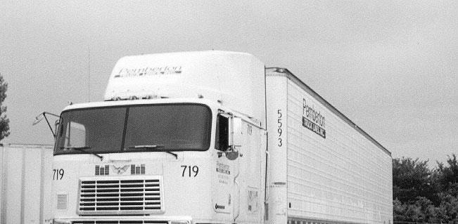
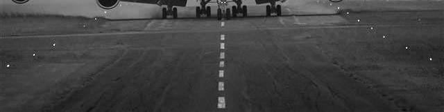
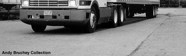
5 Introduction -3 Subsurface stresses in road pavements and airport runways are increased by wheel load on the surface
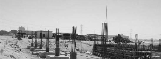

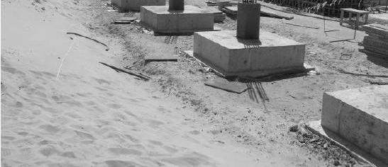
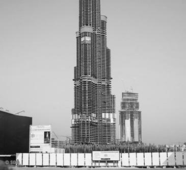

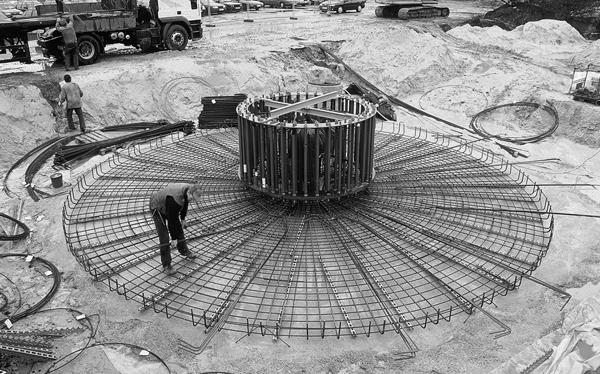
6 Introduction -4 Subsurface stresses in soils are increased by foundation loads Burj Dubai (<700m) Dubai, U. A. E
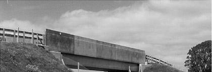
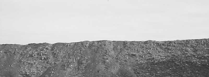
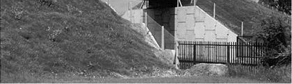
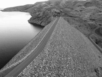
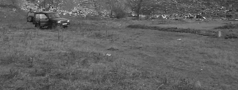
7 Introduction - 5 Embankments and landfills cause to increase subsoil stresses


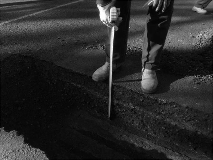
8 Subsoil stress increase -1 It is required to estimate the stress increase in the soil due to the applied loads on the surface. The estimated subsoil stress increase is used: - to estimate settlement of foundation - to check the bearing capacity of the foundation Bearing capacity failure of a raft foundation The Tower of Pisa in Italy, a widely-recognied foundation failure -settlement
9 Subsoil stress increase - The calculation of subsurface stress increase due to the following surface loading conditions will be discussed. Infinitely loaded area Point load (concentrated load) Circular loaded area Strip loading Rectangular loaded area Though the surface loading is caused to increase both vertical and horiontal stresses in soils, only the vertical stress increase is discussed as it is the major stress component for most practical design problems


10 Infinitely loaded area -1 The surface loading area is much larger than the depth of a point where vertical stress increment ( σ) is calculated (e.g. land fills, preloading by soil deposition)
11 Infinitely loaded area - The vertical subsurface stress increment at any depth below the infinitely loaded area is considered to be the same as the surface stress due to external load (filling material) Ground Surface h γ q hγ 1 σ 1 1 σ + 1 σ 1 σ σ + σ σ σ 1 σ q
12 Finitely loaded area If the surface loading area is finite (point, circular, strip, rectangular, square), the vertical stress increment in the subsoil decreases with increase in the depth and the distance form the surface loading area. Methods have been developed to estimate the vertical stress increment in sub-soil considering the shape of the surface loading area.
 developed the following equation to calculate vertical stress increment ( σ σ) in soils due to point load on the surface: Then, 3Q 1 5/ σ 5/ π r 3 1 1+ I p σ Q I p Influence factor, I")
13 Subsurface stress increment due to a point load -1 For homogeneous (properties are the same everywhere), and isotropic (properties are the same in all direction) soils Boussinesq (1885) (French mathematician) developed the following equation to calculate vertical stress increment ( σ σ) in soils due to point load on the surface: Then, 3Q 1 5/ σ 5/ π r I p σ Q I p Influence factor, I p π 1+ ( r / ) I p can be obtained numerically or using table where I p is given in terms of r/
14 Subsurface stress increment due to a point load - Influence factor, I P, for vertical stress increment due to point load
15 Example -1 (1) In road pavement design, the standard vehicle axel is defined as an axel with two single wheels as shown below. P L For a particular vehicle group, the standard axel load (P) is given as 80 kn and the distance between two wheels (L) is 1.8 m. What is the vertical stress increment in the sub-grade at 4 m depth directly under a wheel if this axel is running. (consider wheel load as a point load)
16 y 40kN A Z4m σ r 1.8 m 40kN B x 5/ Example -1 () Find: σ σ σ Α + σ B σ Q ( I p ) B π 1+ ( r / ) π 1+ (1.8/ 4) I p 5/ ( I p ) A 3 1 π 1+ ( r / ) 5/ 3 1 π 1+ (0 / 4) 5/ Therefore, σ Q QB A ( I p ) A + ( I p ) B kpa
17 Subsurface stress increment due to circular loaded area -1

18 5/ 0 1 ) 3( ) ( + r dr d r q d π θ σ Considering force on the small element (black) And applying Boussinesq equation, the stress Increase at A caused by this load Subsurface stress increment due to circular loaded area - Subsurface stress increment due to circular loaded area - By integration of Boussinesq solution over the By integration of Boussinesq solution over the whole circular area, the vertical whole circular area, the vertical stress stress increment at depth under the centre (at A) increment at depth under the centre (at A) I c q B q 0 3/ σ The influence factor I c can be calculated numerically or can be obtained from a table 5/ r Q π σ

19 Subsurface stress increment due to circular loaded area -3 Similar integration can be performed to obtain the vertical stress increase at A, located a distance r from the centre of the loaded area at a depth. This table can be used to calculate I c corresponding to A.
20 Subsurface stress increment due to strip loading -1
21 Vertical stress increment due to strip area carrying uniform pressure Soil is homogeneous, isotropic The stress increment at point X ( σ ) due to a uniform pressure q on a strip area of width B and infinite length is given by in terms of α and β α β σ q σ + + π { α sinα cos( α β )}
22 Vertical stress increment due to strip area carrying increasing pressure Soil is homogeneous, isotropic B X The stress increment at point X ( σ ) due to increasing pressure from ero to q on a strip area of width B and infinite length is given by in terms of α and β the lengths R 1 and R R 1 q R α β σ X q X 1 σ α sin π B β
23 Example - A strip footing m wide carries a uniform pressure of 50 kpa on the surface of a deposit of sand. Water table is at the surface and the saturated unit weight of sand is 0 kn/m 3. Determine the effective vertical stress at a point 3 m below the centre of the footing before and after the application of the surface pressure Before loading Total vertical stress at 3 m depth, σ v σ v γ sat kPa Pore water pressure at 3 m depth, u u γ w kpa Effective vertical stress at 3 m depth, σ v σ v ' σ v u kpa
24 Strip area carrying uniform pressure -Example After loading B m, q 50 kpa, 3 m, β α σ q σ + π { α + sinα cos( α β )} At the centre of the strip, β α/ Therefore, cos(α+β)1 α tan α tan 3 sinα ' radians The increase in stress at 3 m depth due to applied load q 50 σ 0 π π Hence, total effective vertical stress kpa ( α + sin α ) ( ) 99. kpa


25 Subsurface stress increment due to rectangularly/ squarely loaded area -1
 π 3q 0 ( dx dy) [ ] x + y + 5/ 3 By integration of Boussinesq solution over complete area, the vertical stress increment at depth under the centre (at A) L B σ L B y 0 x 0 π 3q 0")
26 Vertical stress increment due to uniformly loaded rectangular area -1 Considering force on the small element (black) and applying Boussinesq equation, the stress Increase at A caused by this load 3Q 1 σ π 1+ r 5/ d( σ ) π 3q 0 ( dx dy) [ ] x + y + 5/ 3 By integration of Boussinesq solution over complete area, the vertical stress increment at depth under the centre (at A) L B σ L B y 0 x 0 π 3q 0 ( dx dy) 3 [ x y ] + + 5/ q 0 I r
27 Vertical stress increment due to uniformly loaded rectangular area - The stresses increase under a corner of a uniformly loaded flexible rectangular area: σ q 0 I r Influence factor for rectangular footing, I r I r 1 mn(m +n +1) 1/. m +n + 4π m +n -m n +1 m +n +1 + mn(m +n +1) tan-1 m +n -m n +1 +1) 1/ Define m B/ and n L/ Solution by numerically or tables
28 Influence factor, I r, for vertical stress increment due to uniformly loaded rectangular area -1

29 Influence factor, I r, for vertical stress increment due to uniformly loaded rectangular area -
30 Rectangular area The vertical stress increment at a depth below point O, σ q ( I + I + I + I )
31 Determine the increase in stress at A and A below a rectangular area Example -3 At the centre of rectangular or square area, σ q ( ) 0 I1 + I + I3 + I 4 I B m m 1 I I3 I 4 A A σ σ n A B or A L σ 0.5, B or L 1.5 ' na' 0.3, I A' 5 A' I A 4 q 0 ( I ) Then, 0 L 1.5 m 4*100*0.084 A A' 4*100* kpa kpa 0.037
32 Example 4 (1) A rectangular foundation 6 X 3 m carries a uniform pressure of 300 kpa near the surface of a soil mass. Determine the vertical stress at a depth of 3 m below point A on the centre line 1.5 m outside the long edge of the foundation. Hint: use the principle of superposition
33 Example - 4 () Using the principle of superposition the problem is dealt as shown below For the two rectangles (1) carrying a positive pressure of 300 kpa, B 3.0 m, L 4.5 m, m B/ 3.0/ , n L/ 4.5/ Therefore, I r (from the table) For the two rectangles () carrying a negative pressure of 300 kpa, B 1.5 m, L 3.0 m, m B/ 1.5/ , n L/ 3.0/ Therefore, I r 0.10 (from the table) Hence, vertical stress increase at A ( a depth of 3 m), σ ( ) A ( q0 I r ) 1 + ( q0i r ) ( ) ( ) 44kPa
34 Influence chart for vertical stress increase - 1 Newmark (194) constructed influence chart, based on the Boussinesq solution to determine the vertical stress increase at any point below an area of any shape carrying uniform pressure. Then, vertical stress increase at σ q o N Chart consists of influence areas which has a influence value of per unit pressure The loaded area is drawn on tracing paper to a scale such that the length of the scale line on the chart is equal to the depth Position the loaded area on the chart such that the point at which the vertical stress required is at the centre of the chart. The count the number of influence areas covered by the scale drawing, N
35 Influence chart for vertical stress increase - Use of Newmark s chart to calculate stress increment at A, ( at a depth of 3.0 m) Z 3.0 m q kpa Then, vertical stress increase at 3 m below point A σ q o N X 300 X kpa The scale line represents 3 m The scale to which the rectangular loading area must be drawn The area is positioned on the chart such that A is at the centre The number of influence areas covered by the rectangle, N 30 (approximately)
36 Approximate method to determine the stress subsurface stress increment (60 0 approximation) According to this method, the increase in stress at depth is σ ( B q 0 + B )( L L + )
37 Example 5 (1) 3 m Compare the stress increase occurring m below the centre of a 3m by 3m square foundation imposing a bearing pressure of 145 kn/m when: 145 kn / m PLAN VIEW (i) The Boussinesq stress distribution is assumed (ii) The 60 0 approximation is assumed SECTIONAL VIEW
38 (i) Example 5 () The Boussinesq stress distribution is assumed q ( ) 0 I1 + I + I3 + I 4 σ 1 L 3 m L 1.5 m When the centre is considered, I 1 I I3 I σ Then, 4 q 0 ( I ) q 145 m 0 kn / 145kN/ m PLAN VIEW B' L' 1.5 m m n B' or L' , I σ m 4*145* kpa SECTIONAL VIEW
39 Example 5 () (ii) The 60 0 approximation is assumed B L 3. 0 m L + q 145 m 0 kn / L B q 145 m 0 kn / m σ At m depth, q 0 ( B + B L )( L + ) (B + ) B 145kN/ m σ (3 + )(3 + ) kn / m σ SECTIONAL VIEW
40 END
STRESSES IN SOIL MASS
 CHAPTER 4 Prepared by: Dr. Farouk Majeed Muhauwiss Civil Engineering Department College of Engineering Tikrit University STRESSES IN SOIL MASS 4.1 DEFIFINTIONS VERTTICAL STRESS Occurs due to internal or
Chapter (5) Allowable Bearing Capacity and Settlement
 Allowable Bearing Capacity and Settlement") Chapter (5) Allowable Bearing Capacity and Settlement Introduction As we discussed previously in Chapter 3, foundations should be designed for both shear failure and allowable settlement. So the allowable
Chapter (5) Allowable Bearing Capacity and Settlement Introduction As we discussed previously in Chapter 3, foundations should be designed for both shear failure and allowable settlement. So the allowable
Soil that t support foundation subjected to net stresses increases. Net stresses increases depend on
 Stresses in a Soil Mass updated pril 15, 008 Haro Dwito rmono, M.Eng, Ph.D Soil that t support foundation subjected to net stresses increases Net stresses increases depend on oad per unit area to which
VERTICAL STRESS INCREASES IN SOIL TYPES OF LOADING. Point Loads (P) Line Loads (q/unit length) Examples: -Posts
 Line Loads (q/unit length) Examples: -Posts") VERTICAL STRESS INCREASES IN SOIL Point Loads (P) TYPES OF LOADING Line Loads (q/unit length) Revised 0/014 Figure 6.11. Das FGE (005). Examples: -Posts Figure 6.1. Das FGE (005). Examples: - Railroad
VERTICAL STRESS INCREASES IN SOIL Point Loads (P) TYPES OF LOADING Line Loads (q/unit length) Revised 0/014 Figure 6.11. Das FGE (005). Examples: -Posts Figure 6.1. Das FGE (005). Examples: - Railroad
Geotechnical Properties of Soil
 Geotechnical Properties of Soil 1 Soil Texture Particle size, shape and size distribution Coarse-textured (Gravel, Sand) Fine-textured (Silt, Clay) Visibility by the naked eye (0.05 mm is the approximate
Stresses and Strains in flexible Pavements
 Stresses and Strains in flexible Pavements Multi Layered Elastic System Assumptions in Multi Layered Elastic Systems The material properties of each layer are homogeneous property at point A i is the same
The following is an exhaustive list of assumptions made by Boussinesq in the derivation of his theory:
 8 Vertical Stresses below Applied Loads 8.1 ntroduction Estimation of vertical stresses at any point in a soil-mass due to external vertical loadings are of great significance in the prediction of settlements
both an analytical approach and the pole method, determine: (a) the direction of the
 the direction of the") Quantitative Problems Problem 4-3 Figure 4-45 shows the state of stress at a point within a soil deposit. Using both an analytical approach and the pole method, determine: (a) the direction of the principal
Quantitative Problems Problem 4-3 Figure 4-45 shows the state of stress at a point within a soil deposit. Using both an analytical approach and the pole method, determine: (a) the direction of the principal
Examples to verify and illustrate ELPLA
 Determining contact pressures, settlements, moments and shear forces of slab foundations by the method of finite elements Version 2010 Program authors: M. El Gendy A. El Gendy GEOTEC: GEOTEC Software Inc.
Supplementary Problems for Chapter 7
 Supplementary Problems for Chapter 7 Problem 7.1 consolidation test has been carried out on a standard 19 mm thick clay sample. The oedometer s deflection gauge indicated 1.66 mm, just before the removal
Theory of Shear Strength
 MAJ 1013 ADVANCED SOIL MECHANICS Theory of Shear Strength Prepared by, Dr. Hetty 1 Strength of different materials Steel Concrete Soil Tensile strength Compressive strength Shear strength Complex behavior
INTI COLLEGE MALAYSIA
 EGC373 (F) / Page 1 of 5 INTI COLLEGE MALAYSIA UK DEGREE TRANSFER PROGRAMME INTI ADELAIDE TRANSFER PROGRAMME EGC 373: FOUNDATION ENGINEERING FINAL EXAMINATION : AUGUST 00 SESSION This paper consists of
Analysis of Load-Settlement Relationship for Unpaved Road Reinforced with Geogrid
 ISGSR7 First International Symposium on Geotechnical Safety & Risk Oct. 8~9, 7 Shanghai Tongji University, China Analysis of Load-Settlement Relationship for Unpaved Road Reinforced with Geogrid Y. C.
Theory of Shear Strength
 SKAA 1713 SOIL MECHANICS Theory of Shear Strength Prepared by, Dr. Hetty 1 SOIL STRENGTH DEFINITION Shear strength of a soil is the maximum internal resistance to applied shearing forces The maximum or
FUNDAMENTALS SOIL MECHANICS. Isao Ishibashi Hemanta Hazarika. >C\ CRC Press J Taylor & Francis Group. Taylor & Francis Group, an Informa business
 SOIL MECHANICS FUNDAMENTALS Isao Ishibashi Hemanta Hazarika >C\ CRC Press J Taylor & Francis Group Boca Raton London New York CRC Press is an imprint of the Taylor & Francis Group, an Informa business
water proofing will relatively long time fully completed) be provided 10 storey building (15x25m) original GWT position 1 sat = 20 kn/m 3
 be provided 10 storey building (15x25m) original GWT position 1 sat = 20 kn/m 3") P1 Question: An excavation will be made for a ten storey 15x25 m building. Temporary support of earth pressure and water pressure will be made by deep secant cantilever pile wall. The gross pressure due
P1 Question: An excavation will be made for a ten storey 15x25 m building. Temporary support of earth pressure and water pressure will be made by deep secant cantilever pile wall. The gross pressure due
This document downloaded from vulcanhammer.net vulcanhammer.info Chet Aero Marine
 This document downloaded from vulcanhammer.net vulcanhammer.info Chet Aero Marine Don t forget to visit our companion site http://www.vulcanhammer.org Use subject to the terms and conditions of the respective
Time Rate of Consolidation Settlement
 Time Rate of Consolidation Settlement We know how to evaluate total settlement of primary consolidation S c which will take place in a certain clay layer. However this settlement usually takes place over
Chapter (11) Pile Foundations
 Pile Foundations") Chapter (11) Introduction Piles are structural members that are made of steel, concrete, or timber. They are used to build pile foundations (classified as deep foundations) which cost more than shallow
Chapter (11) Introduction Piles are structural members that are made of steel, concrete, or timber. They are used to build pile foundations (classified as deep foundations) which cost more than shallow
The theories to estimate lateral earth pressure due to a strip surcharge loading will
 Chapter LITERATURE REVIEW The theories to estimate lateral earth pressure due to a strip surcharge loading will be introduced in this chapter. Commonly geotechnical engineers apply the equations suggested
Prof. B V S Viswanadham, Department of Civil Engineering, IIT Bombay
 51 Module 4: Lecture 2 on Stress-strain relationship and Shear strength of soils Contents Stress state, Mohr s circle analysis and Pole, Principal stressspace, Stress pathsin p-q space; Mohr-coulomb failure
Module 4 (Lecture 16) SHALLOW FOUNDATIONS: ALLOWABLE BEARING CAPACITY AND SETTLEMENT
 SHALLOW FOUNDATIONS: ALLOWABLE BEARING CAPACITY AND SETTLEMENT") Topics Module 4 (Lecture 16) SHALLOW FOUNDATIONS: ALLOWABLE BEARING CAPACITY AND SETTLEMENT 1.1 STRIP FOUNDATION ON GRANULAR SOIL REINFORCED BY METALLIC STRIPS Mode of Failure Location of Failure Surface
Topics Module 4 (Lecture 16) SHALLOW FOUNDATIONS: ALLOWABLE BEARING CAPACITY AND SETTLEMENT 1.1 STRIP FOUNDATION ON GRANULAR SOIL REINFORCED BY METALLIC STRIPS Mode of Failure Location of Failure Surface
TABLE OF CONTENTS CHAPTER TITLE PAGE TITLE PAGE DECLARATION DEDIDATION ACKNOWLEDGEMENTS ABSTRACT ABSTRAK
 TABLE OF CONTENTS CHAPTER TITLE PAGE TITLE PAGE DECLARATION DEDIDATION ACKNOWLEDGEMENTS ABSTRACT ABSTRAK TABLE OF CONTENTS LIST OF TABLE LIST OF FIGURES LIST OF SYMBOLS LIST OF APENDICES i ii iii iv v
Foundation Analysis LATERAL EARTH PRESSURE
 Foundation Analysis LATERAL EARTH PRESSURE INTRODUCTION Vertical or near-vertical slopes of soil are supported by retaining walls, cantilever sheet-pile walls, sheet-pile bulkheads, braced cuts, and other
Chapter (3) Ultimate Bearing Capacity of Shallow Foundations
 Ultimate Bearing Capacity of Shallow Foundations") Chapter (3) Ultimate Bearing Capacity of Shallow Foundations Introduction To perform satisfactorily, shallow foundations must have two main characteristics: 1. They have to be safe against overall shear
Chapter (3) Ultimate Bearing Capacity of Shallow Foundations Introduction To perform satisfactorily, shallow foundations must have two main characteristics: 1. They have to be safe against overall shear
 QUESTION BANK DEPARTMENT: CIVIL SUBJECT CODE / Name: CE 2251 / SOIL MECHANICS SEMESTER: IV UNIT 1- INTRODUCTION PART - A (2 marks) 1. Distinguish between Residual and Transported soil. (AUC May/June 2012)
SEM-2016(01HI CIVIL ENGINEERING. Paper Answer all questions. Question No. 1 does not have internal choice,
 Roll No. Candidate should write his/her Roll No. here. Total No. of Questions : 5 No. of Printed Pages : 8 SEM-2016(01HI CIVIL ENGINEERING Paper - 11 Time : 3 Hours ] [ Total Marks : 300 Instructions to
Chapter (4) Ultimate Bearing Capacity of Shallow Foundations (Special Cases)
 Ultimate Bearing Capacity of Shallow Foundations (Special Cases)") Chapter (4) Ultimate earing Capacity of Shallow Foundations (Special Cases) Ultimate.C. of Shallow Foundations (Special Cases) Introduction The ultimate bearing capacity theories discussed in Chapter 3
Chapter (4) Ultimate earing Capacity of Shallow Foundations (Special Cases) Ultimate.C. of Shallow Foundations (Special Cases) Introduction The ultimate bearing capacity theories discussed in Chapter 3
K Design Graphs and Charts for Raft Foundations Spanning Local Depressions
 K Design Graphs and Charts for Raft Foundations Spanning Local Depressions The reader is advised to read the text in Chapter 13 before using these charts. The charts and figures are repeated here for quick
The Bearing Capacity of Soils. Dr Omar Al Hattamleh
 The Bearing Capacity of Soils Dr Omar Al Hattamleh Example of Bearing Capacity Failure Omar Play the move of bearing Capacity failure The Philippine one Transcona Grain Silos Failure - Canada The Bearing
Page 1 of 10. PROFESSIONAL ENGINEERS ONTARIO NATIONAL EXAMINATIONS Mav CIV-A4 GEOTECHNICAL MATERIALS AND ANALYSIS 3 HOURS DURATION
 Page 1 of 10 PROFESSIONAL ENGINEERS ONTARIO NATIONAL EXAMINATIONS Mav 2015 3 HOURS DURATION NOTES: 1. This is a closed book examination. 2. Read all questions carefully before you answer 3. Should you
Liquefaction and Foundations
 Liquefaction and Foundations Amit Prashant Indian Institute of Technology Gandhinagar Short Course on Seismic Design of Reinforced Concrete Buildings 26 30 November, 2012 What is Liquefaction? Liquefaction
(Refer Slide Time 02:20)
") Soil Mechanics Prof. B.V.S. Viswanathan Department of Civil Engineering Indian Institute of Technology, Bombay Lecture 33 Stress Distribution in Soils Lecture No. 6 Students once again we meet. Today s
Soil Mechanics Prof. B.V.S. Viswanathan Department of Civil Engineering Indian Institute of Technology, Bombay Lecture 33 Stress Distribution in Soils Lecture No. 6 Students once again we meet. Today s
Objectives. In this section you will learn the following. Development of Bearing Capacity Theory. Terzaghi's Bearing Capacity Theory
 Objectives In this section you will learn the following Development of Bearing Capacity Theory Terzaghi's Bearing Capacity Theory Assumptions in Terzaghi s Bearing Capacity Theory. Meyerhof's Bearing Capacity
vulcanhammer.net This document downloaded from
 This document downloaded from vulcanhammer.net since 1997, your source for engineering information for the deep foundation and marine construction industries, and the historical site for Vulcan Iron Works
CHARACTERISTICS OF VACUUM CONSOLIDATION COMPARING WITH SURCHARGE LOAD INDUCED CONSOLIDATION
 International Symposium on Geotechnical Engineering, Ground Improvement and Geosynthetics for Human Security and Environmental preservation, Bangkok, Thailand CHARACTERISTICS OF VACUUM CONSOLIDATION COMPARING
VALLIAMMAI ENGINEERING COLLEGE
 VALLIAMMAI ENGINEERING COLLEGE DEPARTMENT OF CIVIL ENGINEERING SUBJECT CODE : CE6405 YEAR : II SUBJECT NAME : SOIL MECHANICS SEM : IV QUESTION BANK (As per Anna University 2013 regulation) UNIT 1- SOIL
Introduction to Geotechnical Engineering. ground
 Introduction to Geotechnical Engineering ground 1 Typical Geotechnical Project Geo-Laboratory ~ for testing soil properties Design Office ~ for design & analysis construction site 2 Shallow Foundations
Tikrit University. College of Engineering Civil engineering Department CONSOILDATION. Soil Mechanics. 3 rd Class Lecture notes Up Copyrights 2016
 Tikrit University CONSOILDATION College of Engineering Civil engineering Department Soil Mechanics 3 rd Class Lecture notes Up Copyrights 2016 Stresses at a point in a soil mass are divided into two main
PRINCIPLES OF GEOTECHNICAL ENGINEERING
 PRINCIPLES OF GEOTECHNICAL ENGINEERING Fourth Edition BRAJA M. DAS California State University, Sacramento I(T)P Boston Albany Bonn Cincinnati London Madrid Melbourne Mexico City New York Paris San Francisco
Chapter 7: Settlement of Shallow Foundations
 Chapter 7: Settlement of Shallow Foundations Introduction The settlement of a shallow foundation can be divided into two major categories: (a) elastic, or immediate settlement and (b) consolidation settlement.
Clayey sand (SC)
") Pile Bearing Capacity Analysis / Verification Input data Project Task : PROJECT: "NEW STEAM BOILER U-5190 Part : A-1 Descript. : The objective of this Analysis is the Pile allowable bearing Capacity Analysis
Pile Bearing Capacity Analysis / Verification Input data Project Task : PROJECT: "NEW STEAM BOILER U-5190 Part : A-1 Descript. : The objective of this Analysis is the Pile allowable bearing Capacity Analysis
Chapter 5 Shear Strength of Soil
 Page 5 Chapter 5 Shear Strength of Soil. The internal resistance per unit area that the soil mass can offer to resist failure and sliding along any plane inside it is called (a) strength (b) shear strength
7. STRESS ANALYSIS AND STRESS PATHS
 7-1 7. STRESS ANALYSIS AND STRESS PATHS 7.1 THE MOHR CIRCLE The discussions in Chapters and 5 were largely concerned with vertical stresses. A more detailed examination of soil behaviour requires a knowledge
SHEAR STRENGTH OF SOIL. Chapter 10: Sections Chapter 12: All sections except
 SHEAR STRENGTH OF SOIL Chapter 10: Sections 10. 10.3 Chapter 1: All sections ecept 1.13 1.14 1.15 1.17 1.18 TOPICS Introduction Components of Shear Strength of Soils Normal and Shear Stresses on a Plane
Dynamic Response of EPS Blocks /soil Sandwiched Wall/embankment
 Proc. of Second China-Japan Joint Symposium on Recent Development of Theory and Practice in Geotechnology, Hong Kong, China Dynamic Response of EPS Blocks /soil Sandwiched Wall/embankment J. C. Chai 1
4. The total exam value is I 00 marks
 PROFESSIONAL ENGINEERS ONTARIO NATIONAL :EXAMINATIONS -May 2016 98-CIV-A4 GEOTECHNICAL MATERIALS AND ANALYSIS 3 HOURS DURATION NOTES: 1. This is a closed book examination. 2. Read all questions carefully
Benefits of Collaboration between Centrifuge Modeling and Numerical Modeling. Xiangwu Zeng Case Western Reserve University, Cleveland, Ohio
 Benefits of Collaboration between Centrifuge Modeling and Numerical Modeling Xiangwu Zeng Case Western Reserve University, Cleveland, Ohio ABSTRACT There is little doubt that collaboration between centrifuge
EN Eurocode 7. Section 3 Geotechnical Data Section 6 Spread Foundations. Trevor L.L. Orr Trinity College Dublin Ireland.
 EN 1997 1: Sections 3 and 6 Your logo Brussels, 18-20 February 2008 Dissemination of information workshop 1 EN 1997-1 Eurocode 7 Section 3 Geotechnical Data Section 6 Spread Foundations Trevor L.L. Orr
HKIE-GD Workshop on Foundation Engineering 7 May Shallow Foundations. Dr Limin Zhang Hong Kong University of Science and Technology
 HKIE-GD Workshop on Foundation Engineering 7 May 2011 Shallow Foundations Dr Limin Zhang Hong Kong University of Science and Technology 1 Outline Summary of design requirements Load eccentricity Bearing
Consolidation of a 1D column
 1 Introduction Consolidation of a 1D column This example simulates a one-dimensional consolidation test. The sides are constrained as in an odometer test. Analytical solutions are available for a case
Prof. B V S Viswanadham, Department of Civil Engineering, IIT Bombay
 28 Module 7: Lecture -3 on Geotechnical Physical Modelling Hydraulic Gradient Similitude Method Example: Uplift behavior of pile in saturated sand profile Applications of Hydraulic Gradient Similitude
Chapter (6) Geometric Design of Shallow Foundations
 Geometric Design of Shallow Foundations") Chapter (6) Geometric Design of Shallow Foundations Introduction As we stated in Chapter 3, foundations are considered to be shallow if if [D (3 4)B]. Shallow foundations have several advantages: minimum
Chapter (6) Geometric Design of Shallow Foundations Introduction As we stated in Chapter 3, foundations are considered to be shallow if if [D (3 4)B]. Shallow foundations have several advantages: minimum
Foundations with D f equal to 3 to 4 times the width may be defined as shallow foundations. TWO MAIN CHARACTERISTICS ULTIMATE BEARING CAPACITY
 oundation Analysis oundations with D f eual to 3 to 4 times the width may be defined as shallow foundations. TWO MAI CHARACTERISTICS o Safe against overall shear failure o Cannot undergo excessive displacement,
Chapter 6 Effective Stresses and Capillary
 Effectie Stresses and Capillary - N. Siakugan (2004) 1 6.1 INTRODUCTION Chapter 6 Effectie Stresses and Capillary When soils are subjected to external loads due to buildings, embankments or excaations,
A. V T = 1 B. Ms = 1 C. Vs = 1 D. Vv = 1
 Geology and Soil Mechanics 55401 /1A (2002-2003) Mark the best answer on the multiple choice answer sheet. 1. Soil mechanics is the application of hydraulics, geology and mechanics to problems relating
Foundation Engineering
 Foundation Engineering Draft Version April 01 S. van Baars PREFACE This book is just a help for the students fort the old course Grundbau. Luxembourg, April 01 Stefan Van Baars CONTENT I SHALLOW FOUNDATIONS...
EAS 664/4 Principle Structural Design
 UNIVERSITI SAINS MALAYSIA 1 st. Semester Examination 2004/2005 Academic Session October 2004 EAS 664/4 Principle Structural Design Time : 3 hours Instruction to candidates: 1. Ensure that this paper contains
BEARING CAPACITY SHALLOW AND DEEP FOUNDATIONS
 BEARING CAPACITY SHALLOW AND DEEP FOUNDATIONS CONTENTS: 1.0 INTRODUCTION 2.0 SHALLOW FOUNDATIONS 2.1 Design criteria 2.2 Spreading load 2.3 Types of foundations 2.4 Ground failure modes 2.5 Definitions
PLAXIS 3D FOUNDATION Validation Manual. version 1.5
 PLAXIS 3D FOUNDATION Validation Manual version 1.5 TABLE OF CONTENTS TABLE OF CONTENTS 1 Introduction...1-1 2 Soil model problems with known theoretical solutions...2-1 2.1 Bi-axial test with linear elastic
3-BEARING CAPACITY OF SOILS
 3-BEARING CAPACITY OF SOILS INTRODUCTION The soil must be capable of carrying the loads from any engineered structure placed upon it without a shear failure and with the resulting settlements being tolerable
Guide to Passing the Civil PE Exam Geotechnical AM Edition 1. Michael Frolov, P.E. Mark F. DeSantis, P.E., PMP
 Guide to Passing the Civil PE Exam Geotechnical AM Edition 1 Michael Frolov, P.E. Mark F. DeSantis, P.E., PMP ii TOPICS Topic Page TOPIC III: Soil Mechanics... 1-67 TOPIC IV: Structural Mechanics... 68-88
Analysis of the horizontal bearing capacity of a single pile
 Engineering manual No. 16 Updated: 07/2018 Analysis of the horizontal bearing capacity of a single pile Program: Soubor: Pile Demo_manual_16.gpi The objective of this engineering manual is to explain how
Ch 4a Stress, Strain and Shearing
 Ch. 4a - Stress, Strain, Shearing Page 1 Ch 4a Stress, Strain and Shearing Reading Assignment Ch. 4a Lecture Notes Sections 4.1-4.3 (Salgado) Other Materials Handout 4 Homework Assignment 3 Problems 4-13,
Module 9 : Foundation on rocks
 LECTURE 32 9.3 BEARING CAPCITY contd... 9.3.2 Safe bearing pressure There are different methods are available to determine the safe bearing pressure on rocks. However, the applicability of different methods
OP-13. PROCEDURES FOR DESIGN OF EMBANKMENT
 Page 1 of 8 WORK INSTRUCTIONS FOR ENGINEERS TYC Compiled by : LSS Checked by : GSS Approved by : OP-13. PROCEDURES FOR DESIGN OF EMBANKMENT Page of 8 13.0 13.1. OVERALL PROCEDURES This section will briefly
Prof. B V S Viswanadham, Department of Civil Engineering, IIT Bombay
 50 Module 4: Lecture 1 on Stress-strain relationship and Shear strength of soils Contents Stress state, Mohr s circle analysis and Pole, Principal stressspace, Stress pathsin p-q space; Mohr-Coulomb failure
Foundation Engineering Prof. Dr N.K. Samadhiya Department of Civil Engineering Indian Institute of Technology Roorkee
 Foundation Engineering Prof. Dr N.K. Samadhiya Department of Civil Engineering Indian Institute of Technology Roorkee Module 01 Lecture - 03 Shallow Foundation So, in the last lecture, we discussed the
DESIGN AND DETAILING OF COUNTERFORT RETAINING WALL
 DESIGN AND DETAILING OF COUNTERFORT RETAINING WALL When the height of the retaining wall exceeds about 6 m, the thickness of the stem and heel slab works out to be sufficiently large and the design becomes
Third Year. Soil Mechanics Lectures. Students
 Soil Mechanics Lectures 2016-2017 Third Year Students Includes: Stresses within the soil, consolidation theory, settlement and degree of consolidation, shear strength of soil, earth pressure on retaining
Soil strength. the strength depends on the applied stress. water pressures are required
 Soil Strength Soil strength u Soils are essentially frictional materials the strength depends on the applied stress u Strength is controlled by effective stresses water pressures are required u Soil strength
Verification of a Micropile Foundation
 Engineering manual No. 36 Update 02/2018 Verification of a Micropile Foundation Program: File: Pile Group Demo_manual_en_36.gsp The objective of this engineering manual is to explain the application of
D1. A normally consolidated clay has the following void ratio e versus effective stress σ relationship obtained in an oedometer test.
 (d) COMPRESSIBILITY AND CONSOLIDATION D1. A normally consolidated clay has the following void ratio e versus effective stress σ relationship obtained in an oedometer test. (a) Plot the e - σ curve. (b)
FOUNDATION ENGINEERING UNIT V
 FOUNDATION ENGINEERING UNIT V RETAINING WALLS Plastic equilibrium in soils active and passive states Rankine s theory cohesion less and cohesive soil - Coloumb s wedge theory condition for critical failure
Geology and Soil Mechanics /1A ( ) Mark the best answer on the multiple choice answer sheet.
 Mark the best answer on the multiple choice answer sheet.") Geology and Soil Mechanics 55401 /1A (2003-2004) Mark the best answer on the multiple choice answer sheet. 1. Soil mechanics is the application of hydraulics, geology and mechanics to problems relating
Geology and Soil Mechanics 55401 /1A (2003-2004) Mark the best answer on the multiple choice answer sheet. 1. Soil mechanics is the application of hydraulics, geology and mechanics to problems relating
A Simple Algorithm for Analyzing a Piled Raft by Considering Stress Distribution
 Civil Engineering Infrastructures Journal, 47(): 15 7, December 014 ISSN: 3 093 A Simple Algorithm for Analyzing a Piled Raft by Considering Stress Distribution Saeedi Azizkandi, A.R. 1* and Fakher, A.
Chapter (7) Lateral Earth Pressure
 Lateral Earth Pressure") Chapter (7) Lateral Earth Pressure Introduction Vertical or near vertical slopes of soil are supported by retaining walls, cantilever sheet-pile walls, sheet-pile bulkheads, braced cuts, and other similar
Chapter (7) Lateral Earth Pressure Introduction Vertical or near vertical slopes of soil are supported by retaining walls, cantilever sheet-pile walls, sheet-pile bulkheads, braced cuts, and other similar
CHAPTER 8 ANALYSES OF THE LATERAL LOAD TESTS AT THE ROUTE 351 BRIDGE
 CHAPTER ANALYSES OF THE LATERAL LOAD TESTS AT THE ROUTE 351 BRIDGE.1 INTRODUCTION An important objective of this research is to determine whether accurate analyses of the lateral load-deflection behavior
Pile-clayey soil interaction analysis by boundary element method
 Journal of Rock Mechanics and Geotechnical Engineering. 12, 4 (1): 28 43 Pile-clayey soil interaction analysis by boundary element method Mohammed Y. Fattah 1, Kais T. Shlash 1, Madhat S. M. Al-Soud 2
ADVANCED SOIL MECHANICS FINAL EXAM (TAKE HOME):DUE THURSDAY, DECEMBER 19, 6PM.
:DUE THURSDAY, DECEMBER 19, 6PM.") 14.531 ADVANCED SOIL MECHANICS FINAL EXAM (TAKE HOME):DUE THURSDAY, DECEMBER 19, 2013 @ 6PM. Problem #1. Field load tests on strip footings yielded the test data provided below in Figure 1 and Table 1
14.531 ADVANCED SOIL MECHANICS FINAL EXAM (TAKE HOME):DUE THURSDAY, DECEMBER 19, 2013 @ 6PM. Problem #1. Field load tests on strip footings yielded the test data provided below in Figure 1 and Table 1
Settlement and Bearing Capacity of a Strip Footing. Nonlinear Analyses
 Settlement and Bearing Capacity of a Strip Footing Nonlinear Analyses Outline 1 Description 2 Nonlinear Drained Analysis 2.1 Overview 2.2 Properties 2.3 Loads 2.4 Analysis Commands 2.5 Results 3 Nonlinear
SOIL MECHANICS Assignment #5: Stresses in a Soil Mass.
 Geotechnical Engineering Research Laboratory One University Avenue Lowell, Massachusetts 01854 Edward L. Hajduk, D.Eng, PE Lecturer PA105D Tel: (978) 934 2621 Fax: (978) 934 3052 e mail: Edward_Hajduk@uml.edu
OUTCOME 1 - TUTORIAL 3 BENDING MOMENTS. You should judge your progress by completing the self assessment exercises. CONTENTS
 Unit 2: Unit code: QCF Level: 4 Credit value: 15 Engineering Science L/601/1404 OUTCOME 1 - TUTORIAL 3 BENDING MOMENTS 1. Be able to determine the behavioural characteristics of elements of static engineering
Chapter 4. Ultimate Bearing Capacity of Shallow Foundations. Omitted parts: Sections 4.7, 4.8, 4.13 Examples 4.8, 4.9, 4.
 Chapter 4 Ultimate Bearing Capacity of Shallow Foundations Omitted parts: Sections 4.7, 4.8, 4.13 Examples 4.8, 4.9, 4.12 Pages 191-194 Ultimate Bearing Capacity of Shallow Foundations To perform satisfactorily,
INTERPRETATION OF UNDRAINED SHEAR STRENGTH OF UNSATURATED SOILS IN TERMS OF STRESS STATE VARIABLES
 INTERPRETATION OF UNDRAINED SHEAR STRENGTH OF UNSATURATED SOILS IN TERMS OF STRESS STATE VARIABLES S. K. Vanapalli and D.G. Fredlund Department of Civil Engineering University of Saskatchewan, Saskatoon
1.5 STRESS-PATH METHOD OF SETTLEMENT CALCULATION 1.5 STRESS-PATH METHOD OF SETTLEMENT CALCULATION
 Module 6 Lecture 40 Evaluation of Soil Settlement - 6 Topics 1.5 STRESS-PATH METHOD OF SETTLEMENT CALCULATION 1.5.1 Definition of Stress Path 1.5. Stress and Strain Path for Consolidated Undrained Undrained
PILE-SUPPORTED RAFT FOUNDATION SYSTEM
 PILE-SUPPORTED RAFT FOUNDATION SYSTEM Emre Biringen, Bechtel Power Corporation, Frederick, Maryland, USA Mohab Sabry, Bechtel Power Corporation, Frederick, Maryland, USA Over the past decades, there has
(C) Global Journal of Engineering Science and Research Management
 Global Journal of Engineering Science and Research Management") GEOTECHNCIAL ASSESSMENT OF PART OF PORT HARCOURT, NIGER DELTA FOR STRUCTURAL ANALYSIS Warmate Tamunonengiyeofori Geostrat International Services Limited, www.geostratinternational.com. *Correspondence
GEOTECHNCIAL ASSESSMENT OF PART OF PORT HARCOURT, NIGER DELTA FOR STRUCTURAL ANALYSIS Warmate Tamunonengiyeofori Geostrat International Services Limited, www.geostratinternational.com. *Correspondence
Chapter 12: Lateral Earth Pressure
 Part 4: Lateral Earth Pressure and Earth-Retaining Structures Chapter 12: Lateral Earth Pressure Introduction Vertical or near-vertical slopes of soil are supported by retaining walls, cantilever sheetpile
ARC 341 Structural Analysis II. Lecture 10: MM1.3 MM1.13
 ARC241 Structural Analysis I Lecture 10: MM1.3 MM1.13 MM1.4) Analysis and Design MM1.5) Axial Loading; Normal Stress MM1.6) Shearing Stress MM1.7) Bearing Stress in Connections MM1.9) Method of Problem
INFLUENCE VALUES FOR ESTIMATING STRESSES IN ELASTIC FOUNDATIONS RALPH E. FADUM Professor of Soil Mechanics Purdue University
 77 INFLUENCE VALUES FOR ESTIMATING STRESSES IN ELASTIC FOUNDATIONS RALPH E. FADUM Professor of Soil Mechanics Purdue University SUMMARY. This paper deals with the problem of estimating the vertical normal
Calculating methodology of large base slabs: compressible strata capacity and foundation settlement
 Calculating methodology of large base slabs: compressible strata capacity and foundation settlement Veniamin Isaev 1, Andrey Maltsev 1, *, and Andrey Karpov 1 1 Samara State Technical University, Academy
Chapter 5 CENTRIC TENSION OR COMPRESSION ( AXIAL LOADING )
") Chapter 5 CENTRIC TENSION OR COMPRESSION ( AXIAL LOADING ) 5.1 DEFINITION A construction member is subjected to centric (axial) tension or compression if in any cross section the single distinct stress
Chapter 5 CENTRIC TENSION OR COMPRESSION ( AXIAL LOADING ) 5.1 DEFINITION A construction member is subjected to centric (axial) tension or compression if in any cross section the single distinct stress
Slope Stability. loader
 Slope Stability Slope Stability loader Lower San Fernando Dam Failure, 1971 Outlines Introduction Definition of key terms Some types of slope failure Some causes of slope failure Shear Strength of Soils
EXPONENTIAL FOURIER INTEGRAL TRANSFORM METHOD FOR STRESS ANALYSIS OF BOUNDARY LOAD ON SOIL
 Tome XVI [18] Fascicule 3 [August] 1. Charles Chinwuba IKE EXPONENTIAL FOURIER INTEGRAL TRANSFORM METHOD FOR STRESS ANALYSIS OF BOUNDARY LOAD ON SOIL 1. Department of Civil Engineering, Enugu State University
Foundations of High Rise Buildings
 Foundations of High Rise Buildings Prof. Dr.-Ing. Yasser El-Mossallamy Professor of Geotechnical Engineering Ain Shams Univ. Cairo, Egypt c/o Arcadis Consult, Germany y.el-mossallamy@arcadis.de Slide:
Q. 1 Q. 5 carry one mark each.
 GATE 2018 General Aptitude (GA) Set-7 Q. 1 Q. 5 carry one mark each. Q.1 The driver applied the as soon as she approached the hotel where she wanted to take a. The words that best fill the blanks in the
UNIT V. The active earth pressure occurs when the wall moves away from the earth and reduces pressure.
 UNIT V 1. Define Active Earth pressure. The active earth pressure occurs when the wall moves away from the earth and reduces pressure. 2. Define Passive Earth pressure. The passive earth pressure occurs
EARTH PRESSURES ON RETAINING STRUCTURES
 12-1 12. EARTH PRESSURES ON RETAINING STRUCTURES 12.1 Active Pressure and Passive Pressure When a sudden change in level of the ground surface is to be provided for some purpose a retaining structure is
2017 Soil Mechanics II and Exercises Final Exam. 2017/7/26 (Wed) 10:00-12:00 Kyotsu 4 Lecture room
 10:00-12:00 Kyotsu 4 Lecture room") 2017 Soil Mechanics II and Exercises Final Exam 2017/7/26 (Wed) 10:00-12:00 Kyotsu 4 Lecture room Attention: The exam consists of five questions for which you are provided with five answer sheets. Write
2017 Soil Mechanics II and Exercises Final Exam 2017/7/26 (Wed) 10:00-12:00 Kyotsu 4 Lecture room Attention: The exam consists of five questions for which you are provided with five answer sheets. Write