KEYLESS FRICTIONAL SHAFT/HUB LOCKING DEVICES
|
|
|
- Silas Harmon
- 6 years ago
- Views:
Transcription

1 KEYESS FRICTIONA SHAFT/HUB OCKING EVICES THE KEY TO BETTER MACHINE ESIGN IS NO KEY AT A. CATAOG C02


2 INTROUCTION: THE PROBEM: In a typical keye shaft/hub connection, the clearance between key an keyway require for fitting is a serious isavantage when shock or reversing loas are to be transmitte. Any component hel by a key is slipping on the shaft at start-up or loa reversal by an amount equal to the amount of fit clearance. This results in impact loas when contact with the key stops the slippage. These impact loas, which are rarely accounte for in the esign process, generate a continuous pouning between key an keyway. This pouning, combine with fretting corrosion cause by micromovements at the fit interface, frequently leas to shaft failures like the ones illustrate above. [Shaft failure illustrations are reprouce with permission of Sachs, Salvetera & Associates, Solvay, NY.] TRAITIONA INTERFERENCE FITS: The solution to these problems is elimination of the key by using a frictional bon between components an shafts. This type of connection, commonly known as an interference (shrink or press) fit, results in zero clearance hence, no backlash an utilizes the full contact area for uniform transmittal of torques an/or bening moments. Such a connection will never poun out even for an infinite number of loa cycles as long as the frictional holing capacity of the connection is equal to or higher than the loas applie. In aition, the elimination of keyways eliminates keye shaft notch factors, permitting smaller shaft an bearing sizes an reucing the overall cost an complexity of a esign. espite these avantages, mounting an removal problems associate with shrink or press fits have frequently isqualifie this type of connection for many applications. 2
3 THE B-OC SOUTION B-OC Keyless Frictional Shaft/Hub ocking evices provie the ultimate solution by incorporating all the avantages of interference fits, while eliminating mounting an removal problems. B-OC ocking Assemblies an Shrink iscs rely on the proven wege principle to create a keyless, mechanical interference fit by converting locking screw tension into raial contact pressures on shaft an hub. This connection, while in many ways similar to conventional shrink or press fits, has several istinct avantages: 1. In the relaxe position, B-OC keyless connectors provie a generous clearance for easy mounting an ismounting. 2. B-OC keyless connectors generate higher contact pressures than those obtaine by a shrink or press fit, thereby allowing for shorter hub lengths an eliminating the problem of fretting corrosion associate with wier connections.. B-OC keyless connectors facilitate simple axial an angular timing of hub. B-OC CORPORATION: COMMITTE TO QUAITY PROUCTS AN SUPERIOR CUSTOMER SERVICE Since 12, B-OC has been committe to proviing the highest quality keyless locking evices to customers worlwie. All B-OC keyless shaft/hub connectors are manufacture in strict accorance with ISO 002 requirements, an are available in a variety of styles an sizes 1/" up to 0" an larger, both inch an metric to suit any application. B-OC also has the capability to esign an prouce special units, even for small quantity prouction runs. Our application engineers have over years of experience an woul be please to provie free esign assistance for any kin of equipment. Finally, our eicate customer service staff is reay to provie you with prices, stock quantities an elivery information, an can process most orers to ship the same ay. COMPARISON CHART B-OC Keye Connection Spline Connection Q or Taper ock Shrink or Press Fit B-OC Frictional Shaft/Hub ocking evices have Provies a keyless frictional connection Easily mounte & ismounte!!!!!! several istinct Permits simple axial & angular timing! avantages over all other commonly use methos. Transmits reversing bening moments Provies a backlash free connection!!!!
4 OUR PROUCTS B-OC keyless frictional locking evices rely on the proven wege principle to create a mechanical interference fit by converting locking screw tension into raial contact pressures on shaft an hub. We offer many ifferent esigns to suit any application. SERIES B Series 1 outsie the US an Canaa SERIES B Series 1 outsie the US an Canaa esigne for shafts as small as 1/ ( mm) Shallow, single taper esign with integrate push-off threas Exceptional concentricity & ability to transmit bening loas Fixe axial hub position uring assembly Shallow, single taper esign with integrate push-off threas Exceptional concentricity & ability to transmit bening loas Optional spacer sleeve optimizes connections involving narrow hub cross-sections Fixe axial hub position uring assembly SERIES B Series 2 outsie the US an Canaa Shallow, single taper esign with integrate push-off threas Exceptional concentricity & ability to transmit bening loas Axial hub position not fixe uring installation INTERNA EVICES SERIES B00 Series 05 outsie the US an Canaa SERIES B00 Series 1 outsie the US an Canaa SERIES B1 Series 01 outsie the US an Canaa Self-releasing, ouble taper esign permits simple ajustment an removal Not self-centering Available pilot bushings provie pre-centering when require Fixe axial hub position uring assembly Shallow, single taper esign Exceptional concentricity Thin, extra wie sleeves provie low contact pressures allowing for smaller iameter hubs Integrate spacer sleeve eliminates axial hub movement uring installation Heavy uty Wie, ouble taper esign for enhance bening moment capacity Exceptional concentricity Fixe axial hub position uring assembly SERIES B5 Series 0 outsie the US an Canaa Meium uty Wie, ouble taper esign for enhance bening moment capacity Exceptional concentricity Fixe axial hub position uring assembly SERIES B Series 1 outsie the US an Canaa Extra heavy uty Wie, ouble taper esign for enhance bening moment capacity Exceptional concentricity Fixe axial hub position uring assembly EXTERNA EVICES SERIES,, SHRINK ISCS Series 0, 2 an 0 outsie the US an Canaa WK SHAFT COUPINGS Series 0 outsie the US an Canaa External locking evice Provies extremely concentric an wellbalance mechanical interference fit Offere in Stanar, ight, an Heavy uty series Also available in Split an Half Shrink isc esigns ow cost rigi shaft coupling Transmits high torque an bening moments using the same principles as the Shrink isc
5 PROUCT INEX PAGE R = S tan(α + γ) + µ M t = R µ 2 p = R π p H = R π 1 R = S tan(α + γ) + µ M t = R µ 2 p = R π p H = R π R = S tan(α + γ) M t = R µ 2 p = R π p H = R π R = S tan(α + γ) M t = R µ 2 p = R π p H = R π R = S tan(α + γ) + µ M t = R µ 2 p = R π p H = R π 1 R = 2 S tan(α + γ) + µ M t = R µ 2 p = R π p H = R π R = 2 S tan(α + γ) + µ M t = R µ 2 p = R π p H = R π R = 2 S tan(α + γ) + µ M t = R µ 2 p = R π p H = R π 2 R = 2 S tan(α + γ) M t = (R-R cl ) µ 2 p = (R-R cl ) π 2 R = 2 S tan(α + γ) M t = R µ 2 p = R π R = raial loa generate by tightening locking screws R cl = raial loa require to brige fit clearance S = locking screw clamp loa M t = rate torque capacity p = shaft contact pressure p H = hub bore contact pressure α = taper angle γ = friction angle µ = coefficient of friction (= tan γ) = shaft iameter = locking assembly O = locking evice contact length 5
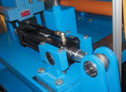
6 APPICATION EXAMPES AE1 B-OC ocking Assemblies an Shrink iscs are operating worlwie in thousans of applications, incluing: AGITATOR SHAFTS BRAKE ISCS BUCKET WHEES BU GEARS CRUSHER ROTORS CUTCHES COUPINGS CRANE WHEES CAMS CONVEYOR PUEYS FYWHEES FANGES SPUR GEARS HYRAUIC MOTORS BEVE GEARS WORM GEARS EVERS PUMP IMPEERS PINION GEARS PINS ROS SHEAVES SHIP PROPEERS SPEE REUCERS SPROCKETS TIMING PUEYS UNIVERSA JOINTS WINCH RUMS AN MORE... AE2 AE AE Miter gear connecte with Series B1 installe over aaptor sleeve that also serves as shaft coupling. Engineere class belt conveyor pulley with avance T-shape en isc connecte to shaft with Series B5. Typical Split Shrink isc arrangement. Narrow, hightorque press gear moifie for repair using both Shrink isc an Series B1 ocking Assembly (aaptor sleeve allows use of larger ocking Assembly, increasing torque capacity of connection).
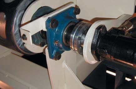
7 AE5 AE Pinion gear connection using Series B1 in application where retainer plate an aaptor sleeve permit axial ajustment of inner race of tapere roller bearing. Thin walle gear hub is reinforce with steel ring installe with light interference. Series B1 esign is similar to Series B1 but with fewer holes in front collar, higher torque capacity an/or wier contact length. AE AE Series B00 an Series B1 use in series for gear with wie hub. Relatively thin hub cross section can be reinforce with steel collar. Series B0 esign with asymmetric tapers offers heavy uty capacity at a reuce cost, but requires shaft shouler for push-off uring isassembly (can also be supplie with collars inverte). AE AE B00 use to mount B-type roller chain sprocket with relatively small hub O. Series B with outer reinforcing collar use as mounting flange for hollow-shaft hyraulic rive with quill bore that is substantially smaller than riven shaft iameter. Shrink isc use to mount mating aaptor flange to motor.
8 AE AE Selective screw tightening on opposing Series B00 units permits precise ajustment of flange pilot an axial an raial runout. Mounting of rive irectly onto riven shaft results in maintenancefree connection. See Page 1 for more information on B-OC sleeve an flange-type rigi couplings. AE AE Series applies thrust against bearing inner race uring assembly in lieu of typical arrangement using lock nut an threae shaft. Socket hea screws an web clearance holes permit tightening of inboar Shrink isc. AE1 AE ow profile flange for isctype flexible couplings (locking screws can be inserte from either en). Slit aaptor sleeve between vertical shaft an Series B acts as shouler to transmit substantial vertical loa into spherical roller thrust bearing.
9 AE1 AE Shrink isc with asymmetric tapers permits mounting of A- plate roller chain sprocket over moifie outer ring where highest torque is generate. Inverte Shrink isc connects coupling flange to counterbore shaft; shaft strength reuction surprisingly low. AE1 AE Moifie Shrink isc for mounting isctype flexible coupling flange in application where low WR 2 value is critical. Series B use to connect lever arm. ocking Assembly connection permits quick an easy timing of several such lever arms mounte on same shaft. AE1 AE Inverte B00 allows for extremely small hub bores. Series B1 supplie with tapere-bore aaptor sleeve use to connect large fan wheel hub irectly to tapere motor shaft.
10 B-OC INTERNA EVICES: OCKING ASSEMBIES ESIGN FEATURES TORQUE B-OC ocking Assemblies are well suite to transmit torque, bening, thrust, an raial loas. Proper selection results in a zero backlash connection free of wear even uner severe reversing loas. Use the following criteria to ai in selecting the right unit for your application: T = peak rive torque = nominal torque multiplie by a variable safety factor to account for stall or start-up conitions, mass accelerations, impact loas, etc. Nominal rive torque can be calculate as follows: M tnom = 52 x HP / rpm Consult with us in cases where T is uncertain. M t = rate torque capacity of (1) B-OC ocking Assembly with all screws tightene to specifie torque M A as liste in specifications. Tabular values are calculate without using a safety factor an shoul be consiere as the point where a connection coul slip if a higher torque is applie. Therefore, you shoul always select a unit where M t T. Torque capacity an contact pressures are a linear function of locking screw tightening torque an may be varie if this is avantageous for certain applications by changing M A within the following limits: Series B00: Series B/B/B: Series B00: Series B1/B: Series B5: up to % higher or up to % lower up to % lower up to % lower up to 0% lower up to % lower In installations where two or more B-OC ocking Assemblies are arrange in series with access to locking screws from one sie only, total torque capacity is not a linear function of the number of units applie. In these situations, the factor f mu shoul be use to compute total torque capacity, as follows: M t total = n x M t x f mu THRUST F ax = transmissable thrust, etermine by using the following equation: x M F ax = t, where = shaft iameter (in) TORQUE AN THRUST COMBINE Simultaneous transmission of torque an thrust requires calculating a resultant torque: M tres = T 2 + (F x / 2) 2, where: T = peak rive torque (ft-lbs) F = peak thrust loa = shaft iameter (ft) Select a unit where M t M tres. BENING MOMENTS Bening moments are a crucial sizing factor in applications where a raial loa from chain pull, the weight of components, etc., acts significantly outsie the locking assembly centerline. Typical applications inclue rolls or conveyor pulleys where shaft eflection ue to raial loas results in a bening moment between shaft an en isc. Generally, bening moments change from a positive to a negative value uring each rotation an are esignate as rotating or reversing bening moments. B-OC ocking Assemblies are well suite to transmit rotating/reversing bening moments. As a result of numerous successful heavy-uty applications in conveyor pulleys an pertinent investigations by inepenent institutions, the following bening moment capacities apply: Series Bening Moment Capacity B00 = 0. x M t B, B, B, B00 = 0.2 x M t B5 = 0.2 x M t B1 an B = 0.5 x M t Consult with us for applications where the bening moment capacity excees these recommene limits. Factors f mu for etermining total torque capacity in multiple unit ocking Assembly installations ocking Assembly n = number of units in series Type 2 B00 & B B5.0.5 N/A B1.5 N/A N/A B.0 N/A N/A TORQUE AN BENING COMBINE Simultaneous transmission of torque an bening requires calculating a resultant torque: M tb = T 2 + (2M b ) 2, where: T = peak rive torque (ft-lbs) M b = bening moment (ft-lbs) Select a unit where M t M tb an M b is within the limits shown above.
11 CONCENTRICITY B-OC ocking Assemblies provie goo to perfect concentricity in a variety of applications. The level of concentricity epens on taper angle an length, hub pre-centering, an moe of screw tightening. The following escription of features shoul be helpful in selecting the most suitable evice to meet specific concentricity requirements. TEMPERATURE INFUENCE Similar to conventional shrink or press fits, B-OC ocking Assembly connections are not affecte by temperature changes as long as they apply equally to hub an shaft. Since temperatures above 00 eg. F lower the strength of most commonly use materials, special consierations are necessary for connections working in temperatures higher than 00 eg. F. SERIES B00: The relatively narrow with of these ouble collar evices usually necessitates the nee for a pre-centering hub section. Type of fit as well as the length of this pre-centering section greatly influences concentricity. The use of pilot bushings permits the reuction of hub length or even the elimination of pre-centering hub sections in the case of a roll configuration. These units provie concentricity sufficient for low to meium spee components. SERIES B, B, B, B00: These ocking Assemblies o not require a pre-centering hub section. The I.., O.. an taper of these units are machine in a single set-up ensuring perfect concentricity for the locking assembly itself. Total system concentricity will epen on installe components, but is typically excellent, even for high spee applications. SERIES B5, B1, B: The goo precentering characteristics of these evices, combine with their wie ouble taper esign, provies excellent concentricity for any type of application. RAIA OAS Raial loas are generate by forces applie perpenicular to the centerline of the shaft, an are frequently associate with pin or axle connections. B-OC ocking Assemblies are well suite to provie a tight, backlash-free fit for such connections (see illustration below). F ra = raial loa capacity = x x P, where: = shaft iameter (in) = contact length (in), see spec. tables P = shaft contact pressure (psi) Typical pressure istribution in backlash-free pin connections =pin iameter HOOW SHAFTS SECURING OF OCKING SCREWS REEASABIITY MATERIA Hollow shafts with bores exceeing 5% of outsie iameter usually require a reuction of contact pressures in orer to avoi permanent shaft contraction. Consult with us for the amount of reuction require or for corrective measures available for a trouble-free hollow shaft application. Specifie locking screw tightening torque M A assures sufficient pre-loa so that screws are self-locking, even in cases where B-OC ocking Assemblies are subjecte to extreme vibratory conitions. B-OC ocking Assemblies an Shrink iscs are esigne for fast an easy removal. Our B00 ocking Assemblies, as well as all B-OC Shrink iscs, feature self-releasing tapers. All other types use self-locking tapers for a more efficient clamp loa conversion an higher bening moment capacities. For these units, a sufficient number of integrate push-off holes assure positive ismounting even after many years of service. B-OC ocking Assemblies are manufacture from heat treate high-carbon an alloy steels. Please contact us for applications requiring stainless steel. Corrosion resistance can be improve through the application of inustry stanar plating materials an/or the use of protective cover plates. oa p min. = p - p 0 Explanations: p = contact pressure provie by ocking Ass y. p = contact pressure on projecte contact area loa = x contact length Y. P. = yiel point of pin material UBRICANTS B-OC ocking Assemblies are supplie lightly coate with orinary machine oil. p max. = p + p Y. P.


12
13 B SERIES Screw hea height = screw ia. (mm) Orering Information: Specify series & shaft size (e.g., ocking Assembly Series B ¼ ) arger sizes an sizes not shown are available on request. B METRIC SPECIFICATIONS Push-off screw threas. Notes: 1. Tolerance for shaft an bore is ±.001 for all sizes. 2. Surface finish for shaft an bore is -5 µin RMS. SIZE (Relaxe) M t (in-lbs) ,02 1,0 2,0 2,,5,,05 5, 5,5, p H (psi),2,5, 1, 1,,,, 1,,, 1, 1,,01 1,1 1,, N* Qty. ocking Screws M x M x M x M x M x M x M x M x M x M5 x 1 M5 x 1 M5 x 1 M5 x 1 M5 x 1 M5 x 1 M5 x 1 M5 x 1 M A (in-lbs) B INCH SPECIFICATIONS SIZE 1/ 5/ / 1/2 5/ / / 1 1 1/ 1 / 1 1/ 1 / (Relaxe) M t (in-lbs) ,01 1, 2,1,552, 5,2 5,5,5 p H (psi),2,5, 1,, 1,, 1,,01 1,1 1,, N* Qty. *Require hub O for 5 h.r. steel hub assuming 5 ksi Yiel Point an Stress Reuction Factor C=1 (see Page for etails) ocking Screws M x M x M x M x M x M x M5 x M5 x M5 x M5 x M5 x M5 x M A (in-lbs) Possible esign configurations 1

14 B & B SERIES B Require hub O epens on strength of hub material (see Specifications an Hub Sizing on Page ) Screw hea height = screw ia. (mm) N Bore ia. machine to -0/+T T=.002 for bores up to..00 for bores up to for bores over.00 = Shaft ia. machine to +0/-T Surface finish for shaft an hub bore to be -5 µin RMS ocking screws transfer to integrate push-off holes for isassembly. Orering Information: Specify series & shaft size (e.g., ocking Assembly Series B 0mm) arger sizes an sizes not shown are available on request. Metric socket hea locking screws IN grae. (See M A for tightening torque). Note: Series B also available with optional integrate spacer sleeve (ieal for very narrow rive elements) by specifying B SP when orering. Spacers are 0. wie for sizes to an incluing 1½ (0 mm) an 0. wie for all other sizes. B/ METRIC SPECIFICATIONS ocking Screws x x x x 2 x 55 x 55 5 x 0 x 5 5 x 5 x 0 55 x 5 x 0 5 x 5 0 x 1 5 x 5 0 x 0 5 x 5 0 x 1 5 x 15 0 x 5 1 x 5 0 x 5 1 x 0 x 10 0 x 0 0 x 2 10 x 5 x x 0 0 x 2 0 x 0 x 5 2 x x 55 0 x 5 x 05 0 x x 55 x 5 00 x (B only) (Relaxe) M t (ft-lbs) ,1 1,2 1,1 1,2 2,2,,1,5,1,5 5,2,0,2,2,05,1 1,00,2,5 2,0,,0,1,2,55 0,2, 0,5, 2,, 2, p H (psi) 1, 1,,1,1 1,2 1,2,,52 1,0 1,5 1, 1, 1, 1,0 1,25 1,5 1, 1, 1,1 1, 1,1 1,2 1,2 1, 1,2 1,2,2,55 1,1,,0 1, 1,,,1,5 1,5, 1,,2 N* Qty M x M x M x M x M x M x M x M x M x M x M x M x M x M x M x M x M x M x M x M x 5 M x 5 M x 5 M x 0 M x 0 M x 0 M x 0 M x 0 M x 0 M x 0 M x 0 M x 5 M x 5 M x 5 M1 x M1 x M x M x M x M x M x *Require hub O for 5 h.r. steel hub assuming 5 ksi Yiel Point an Stress Reuction Factor C=1 (see Page for etails) M A [ft-lb] B B
 M t p H M A [ft-lb] / / 0. 0.5 1. 1. (B only) 2. 2. 0. 0. 1 0. 0. 2 1.")
15 B & B SERIES B Orering Information: Specify series & shaft size (e.g., ocking Assembly Series B 2 / ) arger sizes an sizes not shown are available on request. B/ INCH SPECIFICATIONS Note: Flange of Series B locking assemblies shoul be locate insie of hub bore. ocking Screws 1 (Relaxe) M t p H M A [ft-lb] / / (B only) (ft-lbs) 1 (psi) 1, 1, N* Qty. 5 5 M x M x B B 1 1 1/ 1 / 1 1/ 1 / 1 / 1 1/2 1 5/ 1 / 1 / 1 / 1 / 2 2 1/ 2 / 2 1/ 2 / 2 / 2 1/2 2 / 2 / 2 / 2 / 2 / 1/ / / 1/2 / / / / / 5 5 / 5 / / / / / ,0 1,0 1,12 1,2 1, 1, 1,0 1, 1, 1, 2,1 2,11 2,5,2,0,52,0,,2,5,, 5,,0,1,1,5 1,5 1,0, 1, 2,,,0,1,2,1,1 1,2 1,2,,,52,52 1,0 1,0 1,0 1,5 1,5 1,5 1, 1, 1, 1, 1, 1, 1, 1,0 1,0 1,25 1,25 1,5, 1, 1, 1, 1,1 1, 1, 1,1 1,2 1,2 1,2 1, 1,2,2,55,55 1,1,, M x M x M x M x M x M x M x M x M x M x M x M x M x M x M x M x M x M x M x M x M x M x M x M x M x M x M x M x M x M x M x 5 M x 5 M x 5 M x 5 M x 0 M x 0 M x 0 M x 0 M x 0 M x 0 M x 0 M x 0 M x 0 M x *Require hub O for 5 h.r. steel hub assuming 5 ksi Yiel Point an Stress Reuction Factor C=1 (see Page for etails)


16 B00 SERIES 2 1 ** Require hub O epens on strength of hub material (see Specifications an Hub Sizing on Page ) 1 N Bore ia. machine to -0/+T T=.002 for bores up to for bores up to..00 for bores up to for bores up to..00 for bores over. =Shaft ia. machine to +0/-T Surface finish for shaft an hub bore to be -5 µin RMS. Orering Information: Specify series & shaft size (e.g., ocking Assembly Series B / 2 ) arger sizes an sizes not shown are available on request. B00 METRIC SPECIFICATIONS x x x x 2 x 55 x 55 2 x 5 x x 5 0 x 5 2 x 5 5 x 5 x 0 x 0 55 x 5 x 0 5 x 5 0 x 1 5 x 5 0 x 0 5 x 5 0 x 1 5 x 15 0 x 5 1 x 5 0 x 5 1 x 0 x 10 0 x 0 0 x 2 10 x 5 x x 0 0 x 2 0 x 0 x 5 2 x x 55 0 x 5 x 05 0 x x 55 x 5 00 x 5 x 5 0 x 55 x 55 0 x 55 0 x (Relaxe) M t (ft-lbs) ,5 1,55 1,552 1,1 2,0 2,2 2,02,1,0,00 5,2,10,2,,5,0,2 1,1,55 2,0 2,1,2 5,,555, 5,2,,01 5,1 2,0,0 2,1,1 2,, 0,0 1, 5,1 5, Metric socket hea locking screws IN grae. (See M A for tightening torque). (2) or () equally space zinc plate screws provie solely to inicate position of partial pull out threas size B. p H (psi),,,1,1,, 1,5 1,5 1, 1,,,,0,0 2,,5 2, 2,05,5, 2,1,,,,,,,2 2,0 2, 2,05,01,,5,5,,52,5,0 2,2,02,0,,1,2,1,5,, N * Qty ** Recommene pre-centering length in installations without pilot bushings. Provie a minimum.001 clearance (hub concentricity epens on fit clearance). ocking Screws M A (ft-lbs) M x 1 M x 1 M x 1 M x 1 M x 1 M x 1 M x 1 M x 1 M x 1 M x 1 M x M x M x M x M x M x M x M x M x M x M x M x M x M x M x M x M x 5 M x 5 M x 5 M x 5 M x 0 M x 0 M x 5 M x 5 M x M x M x M1 x M1 x M x 0 M x 0 M x 0 M x 0 M x 0 M x 0 M x 0 M x 0 M x 0 M x B M M M M M M M M M M M M M M M M M M M M M M M M M M M M M M M M M M M M M M M M M M2 M2 M2 M2 M M M M *Require hub O for 5 h.r. steel hub assuming 5 ksi Yiel Point an Stress Reuction Factor C=1 (see Page for etails)
17 B00 INCH SPECIFICATIONS / / 1 1 1/ 1 / 1 1/ 1 / 1 / 1 1/2 1 5/ 1 / 1 / 1 / 1 / 2 2 1/ 2 / 2 1/ 2 / 2 / 2 1/2 2 / 2 5/ 2 / 2 / 2 / 2 / 1/ 1/ / / 1/2 / / / / / 1/2 / 5 5 / 5 1/2 / 1/2 / 1/2 / (Relaxe) M t (ft-lbs) , 1, 1, 1, 1, 1, 2,0 2,05 2,5 2, 2, 2, 2,05,000,05,10,1,,,2 5, 5, 5,,05,,0,,1,,,,2,2 1,052 1,,5, 1,2,, 5,,52 52, p H (psi),,,1,,2 1,5 1,5 1, 1,,,,,0,0 2, 2,,5,5, 2, 2, 2, 2,05 2,05 2,1,5,5,, 2,1 2,1,,,0,, 2,,,,,,,2,2 2, 2,05 2,05,01,01,,5, N* Qty ocking Screws M A (ft-lbs) M x 1 M x 1 M x 1 M x 1 M x 1 M x 1 M x 1 M x 1 M x 1 M x M x M x M x M x M x M x M x M x M x M x M x M x M x M x M x M x M x M x M x M x M x M x M x M x M x M x M x M x M x M x M x 5 M x 5 M x 5 M x 5 M x 5 M x 0 M x 0 M x 0 M x 0 M x 5 M x 5 M x B M M M M M M M M M M M M M M M M M M M M M M M M M M M M M M M M M M M M M M M M M M M M M M M M M M M M *Require hub O for 5 h.r. steel hub assuming 5 ksi Yiel Point an Stress Reuction Factor C=1 (see Page for etails) PIOT BUSHINGS FOR METRIC OCKING ASSEMBIES SET SUITABE FOR B00 INCHES MM NUMBER OCKING ASSEMBY SIZES W X PB 55 5 x 5 to 5 x M x PB 05 0 x 1 to 5 x M x 5 PB 0 x 5 to 0 x M x 0 PB 1 1 x to 0 x M x PB x 5 to x M x 55 PB 1 10 x 0 to 0 x M x PB 0 x to 0 x M x 0 PB 2 x M x 0 PB 2 x 55 to 0 x M1 x 0 PB 2 x 05 to 0 x M x 0 PB 2 x 55 to x M x 0 PB 0 x 55 to 0 x M x 1 PB 5 x to 00 x M x 0 () Metric SHCS IN grae. (replacing camium plate locking screws). See table for screw size x. W B-OC PIOT BUSHINGS: for series B00 ocking Assemblies to provie pre-centering in applications with either straight through hub bores or narrow hubs. Pilot Bushings are supplie in sets consisting of three () bushings an three () longer screws. Pilot Bushings for inch size ocking Assemblies are ientical to bushings use for relate metric units except for outsie iameter. 1

18 B00 SERIES Screw hea height = screw ia. (mm) N Require hub O epens on strength of hub material (see Specifications an Hub Sizing on Page ) Bore ia. machine to -0/+T T=.002 for bores up to.00 for bores over ocking screws transfer to integrate push-off holes for isassembly. 2 = Shaft ia. machine to +0/-T Surface finish for shaft an hub bore to be -5 µin RMS Orering Information: Specify series & shaft size (e.g., ocking Assembly Series B00 1 / ) B00 METRIC SPECIFICATIONS Integrate spacer sleeve inclue Metric socket hea locking screws IN grae. (see M A for tightening torque) SIZE x x x x x 1 x 1 x 2 x x 1 x 2 1 x 2 x 2 x 2 x x 2 x x 1 2 x 5 x x 0 x 5 2 x 55 5 x 5 x 2 x 5 55 x 1 x 5 x 0 x 0 5 x 5 0 x 0 5 x 0 x 1 5 x 0 0 x 5 1 x 0 0 x 5 1 x (Relaxe) 1 2 M t p H (ft-lbs) (psi) N* Qty. ocking Screws M A (ft-lbs) M x.55 M x.55 M x.55 M x.55 M x.55 M x.55 M x.55 M x M x M x M x M x M x M x M x M x M x M x M x 1 M x 1 M x 1 M x 1 M x M x M x M x M x M x M x M x M x M x M x M x M x 5 M x 5 M x 5 M x , 1,5 1, 1,0 2,0 2,2,,01 5,,1,,0,5,,5 1, 1,5,5,,,,,55,5,5 1, 1, 1,0,2,1,1 1,1,55,,0,2,1,,,1,,12,,1,,,,5,0,,52,2,, *Require hub O for 5 h.r. steel hub assuming 5 ksi Yiel Point an Stress Reuction Factor C=1 (see Page for etails) 1
19 B00 INCH SPECIFICATIONS SIZE 1/ 5/ / / 1/2 5/ / / / 1 1 1/ 1 / 1 1/ 1 / 1 / 1 1/2 1 5/ 1 / 1 / 1 / 1 / 2 2 1/ 2 / 2 / 2 / 2 1/2 2 5/ 2 / 2 / 2 / 1/ 1/ / / 1/2 5/ / / / 1/ / / 1/2 / / (Relaxe) 1 2 M t (ft-lbs) p H (psi) N* Qty. ocking Screws M A (ft-lbs) M x.55 M x.55 M x.55 M x.55 M x.55 M x M x M x M x M x M x M x M x M x 1 M x 1 M x 1 M x 1 M x M x M x M x M x M x M x M x M x M x M x M x M x M x M x M x M x M x M x M x M x M x M x 5 M x 5 M x 5 M x 5 M x 5 M x 5 M x 5 M x 5 M x ,2 1, 1, 1,5 1, 1,5 1, 2,02 2,1 2,11,1,1,,0,1 5, 5,,,1,,,01,0,5,05,,0,,05, 1,1 1,5,5,,,55,5 1,,2,1,1 1,1,55,,0,2,2,,,,1,,12,12,,,1,1,,,,,,,5,5,0,0,0,,52,52,52,2,2,,,, *Require hub O for 5 h.r. steel hub assuming 5 ksi Yiel Point an Stress Reuction Factor C=1 (see Page for etails) Possible esign configurations Note: In applications where spacer sleeve is remove, the rive element will move axially uring installation an torque ratings an contact pressures increase 5%. 1

20 B1 HEAVY UTY SERIES Screw hea height = screw ia. (mm) 1 N Require hub O epens on strength of hub material (see Specifications an Hub Sizing on Page ) Bore ia. machine to -0/+T T=.002 for bores up to..00 for bores up to for bores up to for bores over.000 ocking screws transfer to integrate push-off holes for isassembly. = Shaft ia. machine to +0/-T Surface finish for shaft an hub bore to be -5 µin RMS Orering Information: Specify series & shaft size (e.g., ocking Assembly Series B1 10mm) arger sizes an sizes not shown are available on request. B1 METRIC SPECIFICATIONS Metric socket hea locking screws IN grae. (see M A for tightening torque) Note: Unique staggere slit on series B1, B, an B5 sizes 0mm an larger prevents permanent eformation of thrust collars that can result from improper isassembly. (Relaxe) M t p H ocking Screws x 55 x 55 2 x 5 x 0 x 5 5 x 5 x 0 55 x 5 x 0 5 x 5 0 x 1 0 x 0 0 x 1 0 x 5 1 x 5 0 x 5 1 x 0 x 10 0 x 0 0 x 2 10 x 5 x x 0 0 x 2 0 x 0 x 5 2 x x 55 0 x 5 x 05 0 x x 55 x 5 00 x 5 x 5 0 x 55 x x 55 0 x 55 5 x x 5 5 x 55 x 5 0 x (ft-lbs) 1 0 1,00 2, 2,,0,,55,,,1 1,02 1, 2,1 2,1,5, 5,2 1,,5 0, 1,5, 12,2 0,2 12,2 2, 1,1,2 0, 1,0 5,2, 55,5,0 1,,1,0 1,0,0 1,05,0 1,5,2 1,, 1,2,2 (psi) 1, 1,,1,1,5,5 1,0 1,0,0 1,5,2,5,0 1,5,,5 1,,0,2, 1,,, 1,5,05,,5,,02,,,,,52,,0 1,,,0,,0,1,10, N* Qty M x 5 M x 5 M x 5 M x 5 M x M x M x 55 M x 55 M x 55 M x 55 M x M x M x M x 0 M x 0 M x 0 M x 0 M x 0 M x 0 M x 0 M x 1 M x 1 M x 1 M x 1 M x 1 M x 1 M x 1 M x 1 M x 1 M x 1 M x 1 M x 0 M x 0 M x 0 M x 0 M x 0 M x 0 M x 0 M x 0 M x 0 M x 0 M x 0 M x 0 M x 0 *Require hub O for 5 h.r. steel hub assuming 5 ksi Yiel Point an Stress Reuction Factor C=1 (see Page for etails) M A (ft-lbs)
21 B1 INCH SPECIFICATIONS 1 1 1/ 1 / 1 1/ 1 / 1 / 1 1/2 1 5/ 1 / 1 / 1 / 2 2 1/ 2 / 2 1/ 2 / 2 / 2 1/2 2 / 2 5/ 2 / 2 / 2 / 2 / 1/ 1/ / / 1/2 5/ / / / 1/ / / 1/2 / / 5 5 1/ 5 / 5 1/2 5 / 5 / / 1/2 / 1/ / 1/2 / / (Relaxe) M t (ft-lbs) ,005 1,0 2,02 2, 2, 2, 2,1,0,,,1,52,0,2,,01,2,,0,,,,52,0,, 1,2 1, 1,0 1,1 1,, 2, 2,0 2,0 2,,2,1,0,5,2 52, 5, 5,,5,,,5,1 1,2 2,0 5,5,01, p H (psi) 1, 1, 1,,1,1,1,5,5,5 1,0 1,0 1,0 1,0 1,0,0,0 1,5 1,5 1,5,2,2,2,2,5,5,5,5,0,0,0,0 1,5 1,5 1,5 1,5,,,5,5,5 1, 1,,0,0,0,2,2, 1, 1,,,,,, 1,5 1,5 1,5 N* Qty. ocking Screws M x 5 M x 5 M x 5 M x 5 M x 5 M x 5 M x M x M x M x 55 M x 55 M x 55 M x 55 M x 55 M x 55 M x 55 M x 55 M x 55 M x 55 M x M x M x M x M x M x M x M x M x M x M x M x M x 0 M x 0 M x 0 M x 0 M x 0 M x 0 M x 0 M x 0 M x 0 M x 0 M x 0 M x 0 M x 0 M x 0 M x 0 M x 0 M x 0 M x 1 M x 1 M x 1 M x 1 M x 1 M x 1 M x 1 M x 1 M x 1 M x 1 M A (ft-lbs) *Require hub O for 5 h.r. steel hub assuming 5 ksi Yiel Point an Stress Reuction Factor C=1 (see Page for etails) Possible esign configurations
 1 N Require hub O epens on strength of hub material (see Specifications an Hub Sizing on Page ) Bore ia. machine to -0/+T T=.002 for bores up to..00 for bores up to.00.00 for bores up to.000.")
22 B5 MEIUM UTY SERIES ocking screws transfer to integrate push-off holes for isassembly. Screw hea height = screw ia. (mm) 1 N Require hub O epens on strength of hub material (see Specifications an Hub Sizing on Page ) Bore ia. machine to -0/+T T=.002 for bores up to..00 for bores up to for bores up to for bores over.000 = Shaft ia. machine to +0/-T Surface finish for shaft an hub bore to be -5 µin RMS Orering Information: Specify series & shaft size (e.g., ocking Assembly Series B5 0mm) B5 METRIC SPECIFICATIONS Metric socket hea locking screws IN grae. (see M A for tightening torque) 0 x 1 0 x 0 0 x 1 0 x 5 1 x 5 0 x 5 1 x 0 x 10 0 x 0 0 x 2 10 x 5 x x 0 0 x 2 0 x 0 x 5 2 x x 55 0 x 5 x 05 0 x x 55 x 5 00 x 5 x 5 0 x 55 x x 55 0 x 55 5 x x 5 5 x 55 x 5 0 x (Relaxe) M t (ft-lbs) 5,1,2, 1,5, 1,2,0 2,,,2,,0 5,, 5,055,1 0,2,,0,2 2,5,,2 0,,2 52,5 552,0 0, 2,0 2,1 5,2 1, 1, 01,5 p H (psi) 1,,1,,2 1,52 1,5,, 1,5 1,5, 1,2, 1, 1,,2,1 2,5,01,,55 1,1 1,2 1,, 1,52 1,2 1, 1, 1,2 1,1 1,2 1, 1, N* Qty ocking Screws M x M x M x M x M x M x M x 0 M x 0 M x 0 M x 0 M x 0 M x 0 M x 0 M x 0 M x 0 M x 0 M x 0 M x 0 M x 0 M x 1 M x 1 M x 1 M x 1 M x 1 M x 1 M x 1 M x 1 M x 1 M x 1 M x 1 M x 1 M x 1 M x 1 M x 1 M A (ft-lbs) B5 INCH SPECIFICATIONS (Relaxe) 1 M t (ft-lbs) p H (psi) N* Qty. 2 / 2 / / 1/2 / / 1/2 / 5 5 / 5 / / / / ,1 5,,,0 1,,5, 2,2,02 2,002,5 2,5 5,,01,2,2 1,,1,,,2 1,5 1,5,,, 1,5 1,5, 1,2 1, 1, M x M x M x M x M x M x M x M x 0 M x 0 M x 0 M x 0 M x 0 M x 0 M x 0 M x 0 M x 0 *Require hub O for 5 h.r. steel hub assuming 5 ksi Yiel Point an Stress Reuction Factor C=1 (see Page for etails) M A (ft-lbs)

 B METRIC SPECIFICATIONS x 0 x 5 0 x 0 x 55 2 x 5 x 05 0 x x 55 0 x 5 x 5 x 5 00 x 55 x 555 0 x 55 x 55 0 x 0 x 5 5 x 55 x 5 5 x 5.0..1..2.0..5 1..1.1..55 1.2 1.1 1. 1.5.2 2.")
23 B EXTRA HEAVY UTY SERIES Screw hea height = screw ia. (mm) Require hub O epens on strength of hub material (see Specifications an Hub Sizing on Page ) 1 N Bore ia. machine to -0/+T T=.00 for bores up to.0.00 for bores up to for bores up to..00 for bores up to for bores over 2.55 = Shaft ia. machine to +0/-T Surface finish for shaft an hub bore to be -5 µin RMS ocking screws transfer to integrate push-off holes for isassembly. Orering Information: Specify series & shaft size (e.g., ocking Assembly Series B mm) Metric socket hea locking screws IN grae. (see M A for tightening torque) B METRIC SPECIFICATIONS x 0 x 5 0 x 0 x 55 2 x 5 x 05 0 x x 55 0 x 5 x 5 x 5 00 x 55 x x 55 x 55 0 x 0 x 5 5 x 55 x 5 5 x (Relaxe) M t (ft-lbs),2,,01 2,5,,5, 5,1 2,000 2, 2,15,, 1,0,5 1,00, 1,2,1 1,, 1,, 1,0, 1,,1 p H (psi),02,55,15,5,15,,02,,0,,0,1,,5,2 2,,,0,,1 N* Qty M x M x M x M x M x M x M x M2 x 0 M2 x 0 M2 x 0 M2 x 0 M2 x 0 M2 x 0 M2 x 0 M2 x 0 M2 x 0 M2 x 0 M2 x 0 M2 x 0 M2 x 0 *Require hub O for 5 h.r. steel hub assuming 5 ksi Yiel Point an Stress Reuction Factor C=1 (see Page for etails) M A (ft-lbs) ,0 1,0 1,0 1,0 1,0 1,0 1,0 1,0 1,0 1,0 1,0 1,0 1, OCKING ASSEMBY CONNECTIONS WITH SHAFT-AAPTOR SEEVES: In applications where an existing shaft iameter oes not fit the bore of a stanar B-OC ocking Assembly, we recommen using an aaptor sleeve size to facilitate the use of a stanar size ocking Assembly an the existing shaft. The maximum wall thickness of an aaptor sleeve shoul be approximately % of the shaft iameter. The minimum thickness will epen upon the machining process. It is important to note that in orer to maximize the torque capacity of a sleeve ocking Assembly connection, the shaft/sleeve bore interface shoul be free of any lubricant, resulting in a coefficient of friction µ = 0. an making the sleeve O/ocking Assembly bore the point of lowest torque capacity (provie the sleeve O is less than 1. times the shaft iameter). This facilitates full use of the larger ocking Assembly s higher torque capacity. Notes: 1. Sleeve I = s -0/+.001 where s = shaft ia. 2. Sleeve O = +0/-T for ocking Assembly to be use.. Install RY at shaft/sleeve bore interface for coefficient of friction µ =0... Torque capacity at sleeve O = M t for ocking Assembly to be use. s 5. Torque capacity on shaft = M t x x 1... Sleeve to be manufacture with one lengthwise slit (after machining) an from material equal to or better than shaft material.. Sleeve can be installe over existing keyway; position slit approximately opposite keyway. 2
24 HUB SIZING B-OC ocking Assemblies transmit torque an other loas by means of mechanical interference generate by pressure exerte on both the shaft an hub, meaning that consieration must be given to the amount of hub material require to prevent permanent expansion (i.e., yieling). The following information is provie to assist you in etermining the require hub O for any ocking Assembly application. Using the stress equations presente at right, the require hub O " N " is etermine as follows: THICK WAE CYINER SUBJECTE TO INTERNA PRESSURE σ t σ r ο ο P i i x THICK WAE CYINER SUBJECTE TO EXTERNA PRESSURE P σ t σ r i ο ο i where = hub bore (inches) from specification tables, an... p = contact pressure (psi) applie to hub bore from H specification tables Y.P. = N = Y.P. + (p x C) H Y.P. - (p x C) yiel point (psi) of hub material (see below) C = Stress Reuction Factor, consiering the relationship of actual hub with "B" (as etermine by customer) to ocking Assembly contact length "" (per specification tables), etermine as follows (assumes locking assembly collar in contact with hub bore is centere in hub): For Series B, B, B, B00 an B00 C = 1.0 for B = C = 0. for B = 1.5 x C = 0. for B = 2.0 x For Series B1, B an B5 C = 1.0 for B = C = 0. for B = 1. x C = 0. for B = 1. x This equation can also be expresse as N =K, where Y.P. + (p x C) H K represents the expression. Y.P. - (p x C) H The table at right provies these K factors for various combinations of Y.P., p, an C. To use the table, H etermine the Yiel Point (in psi) of your hub material, fin the p value for the ocking Assembly you ve H selecte from the appropriate specification table (roun up to the nearest 1,000 psi), an etermine the value of C base on your component s length-thru-bore (TB). Then, fin the K factor from the table an multiply by the ocking Assembly O to calculate the minimum require hub O for your application. H 2 Q + o σ tx = P 1 1 Q 2 x 1+ Q σ ti = P 1 Q Q σ to = 2P 1 Q Q Q σ rx = P 1 i =P i σ ri = P σ ro = 0 o =2P 2 o 1 2 x (v+1)+(v-1)*q ve(1-q) o Q E(1-Q) TANGENTIA STRESSES σ t RAIA STRESSES σ r σ 2 P + i tx = 1 1 Q 2 x σ 2P σ ti = 1 Q 2 P i rx = 1 1 Q 2 x σ ri = 0 σ ro = P COMBINE HUB STRESSES IN SHRINK ISC APPICATIONS σ v i = insie of hub o = outsie of hub v = poisson's ratio (.0 for steel) E = moulus of elasticity (x for steel) PRESSURE EXERTE ON HUB (psi) C =,000,000,000,000,000,000 1,000,000,000,000 1,000 1,000 1,000,000,000,000 2,000,000, EXPANSION/CONTRACTION KEY i =2P i E(1-Q) o =P (v-1)+(v+1)*q o ve(1-q) P = pressure (psi) τ = torsional hub stress 2 Q = K FACTORS FOR HUB MATERIA WITH Y.P. EQUA TO 2,000 psi 5,000 psi 0,000 psi ( σ σ ) τ 2 2 σ v = σ t + σ r t r Q σ to = P 1 Q


25
26 B-OC EXTERNA EVICES: SHRINK ISCS & WK SERIES RIGI SHAFT COUPINGS ESIGN FEATURES TORQUE External locking evices for keyless frictional shaft/hub connections on shafts from 5/ to 0 iameter, B-OC Shrink iscs... Provie a high capacity interference fit with all the positive features of conventional interference fits, but without their assembly an ismounting problems. Offer extremely concentric an well-balance connections, ieal for high-spee applications. Permit simple axial an angular timing. Are available in stanar, light, an heavy-uty series to suit any application. WORKING PRINCIPE The ouble tapere inner ring of a B-OC Shrink isc provies a high-ratio conversion of screw clamp loas into raial contact pressures when the outer collars are pulle together by tightening of the integrate highstrength locking screws. These raial contact pressures in turn accomplish the following: 1. Contract the inner ring an hub to brige the clearance between shaft an hub bore. 2. Generate a efine shaft/hub contact pressure for a high capacity mechanical interference fit. This frictional bon transmits torque, bening an/or thrust loas irectly from the hub to the shaft; the Shrink isc itself oes not carry any torque or thrust loa. M t = rate torque capacity of (1) B-OC Shrink isc with all screws tightene to specifie torque M A as liste in specifications, base on a coefficient of friction µ = 0. an specifie tolerances an clearances. Torque capacities for Half Shrink iscs = M t / 2. Torque capacities for connections using shaft iameters between the minimum an maximum sizes liste can be approximate through interpolation. Transmissible torque ecreases if tolerances an/or clearances are larger than specifie; or if hollow shafts with bores exceeing 5% of shaft iameter are use. THRUST F ax = transmissable thrust, etermine by using the following equation: x M F ax = t, where = shaft iameter (in) TORQUE AN THRUST COMBINE REEASEABIITY Simultaneous transmission of torque an thrust requires calculating a resultant torque: M tres = T 2 + (F x / 2) 2, where: T = peak rive torque (ft-lbs) F = peak thrust loa = shaft iameter (ft) Select a unit where M t M tres. BENING MOMENTS MATERIA UBRICANTS Shrink iscs will generally transmit a continuous bening moment equal to % of rate torque capacity M t. Since the tapers of a B-OC Shrink isc are selfreleasing an stresses from raial contractions of the hub are well within elastic limits, relaxing of the locking screws results in hub expansion back to its original imensions, thereby restoring fit clearance for simple isassembly. Shrink isc inner rings are manufacture from high-carbon steel. Outer rings are mae from forge an heat treate alloy steel. Shrink iscs are supplie with Molybenum isulphie base lubricant applie to the tapers an to the locking screw threas an hea contact areas. SHAFT AN HUB MATERIA iste specifications assume shaft an hub material with a yiel point of at least 5,000 psi. Cast iron hubs are well suite for compressive stresses exerte by B-OC Shrink iscs. However, a lower torsional hub strength generally requires the selection of a Shrink isc at least one size larger than liste if full torque (i.e., that applicable to a steel hub) is to be transmitte. 2
27 ENGTH OF FIT The most recent research on length of fit for a Shrink isc connection* inicates that the hub bore-to-shaft interface shoul be relieve using a non-tolerance clearance except for that portion irectly uner the Shrink isc inner ring, for a fit length equal to for a stanar Shrink isc (see illustration at right). This approach eliminates fretting corrosion between shaft an hub which can make the separation of components ifficult. *(see Casper, Thomas: Reibkorrosionsverhalten von Spanelementverbinungen - Aachen: Mainz, 1) Recommen ength of Fit Equals OCATING AGAINST HUB FACE In applications subjecte to reversing bening moments, we recommen the configuration at right which requires a hub unercut where R e for smooth transition. e R e REGARING SINGE TAPER SHRINK ISCS We generally o not avocate this esign ue to the following limitations: Reuce effective contact length results in significantly higher ynamic fit pressures in applications with bening moments Shallow taper angle means units are not selfreleasing; removal can be ifficult We offer Single Taper Shrink iscs only upon request. 2
 Stanar Shrink isc *See table at left for maximum iametrical clearance between shaft an hub bore.")
28 SHRINK ISCS STANAR, IGHT, AN HEAVY UTY EXTERNA OCKING EVICES H 1 e shaft iameter* Shaft s To an Over Incluing Maximum iametrical Clearance Between Shaft an Hub Bore 1 1/ 1 / / 1 1/ 1 / / Metric hex hea locking screws IN 1 grae. (see M A for tightening torque) Stanar Shrink isc *See table at left for maximum iametrical clearance between shaft an hub bore. Surface finish for shaft an bore, as well as for hub O, to be -5 µin RMS. S SERIES SPECIFICATIONS (Shrink isc bore/hub O) Hub O tolerance + 0 / / / / / Shaft iameter Range min max min. shaft ,00 1, 1,00 2,,0,0,0,0 1,5 1,5 2,,5 1,0 5,0 1,5 0,0 1,0 1,00 1,0,0,0,10 0,,0, 5, 2, 5,00,2,0 1,0,00 1,,10 STANAR UTY M t (ft-lbs) for max. shaft 2 0 1,0 1,0 1,0 2, 2,,00,,,0, 1,2 2,,0,0,0 5,,, 5,0 1,0,0 2, 5, 5,0, 2,0 5,,, 2,0 52,0 1,05,0 1,15, 1,,0 ocking Screws M A Qty. (ft-lbs) M5 x M5 x 1 M x M x M x M x M x M x M x M x M x M x 5 M x 0 M x 0 M x 5 M x M x 55 M x 55 M x 5 M x 5 M x 5 M x 5 M x 0 M x 0 M x 0 M x 0 M x 0 M x 1 M x 1 M x 1 M x 0 M x 0 M x 1 M x 1 M x 1 M x 0 M2 x Bolt Circle ia (Relaxe) H e a R 1/ 1/ 1/ 1/ 1/ /2 /2 /2 1/ 1/ 1/ 1/ 1/ 1/ / / / / / / / 1/ 1/ 1/ 5/ 5/ 5/ 5/ 5/ 5/ 5/ / / / / 1/2 1/ ,1 1, Notes: 1. Inner Rings of all Shrink iscs are supplie with (1) lengthwise slit 2. Shrink iscs are available for shafts up to 0 ia. an in a variety of special esigns.. Max. shaft sizes liste for Series an Series Shrink iscs reflect equal section mouli of shaft an hub (max. shaft ia.= ) Screw Split Shrink isc Half Shrink isc HT Specifications for Web Clearance Holes (iameter in inches) M5 M M M M M M M M
 S SERIES SPECIFICATIONS 5-0- 5-5- 15- - - 0-0- 2- - 0- - 0- - - 0- - - 0- (Shrink isc bore/hub O). 5.5.2..0.2..1..2.0..5 1..1.1.5.55 1.")
29 Orering Information: Specify series & size when orering (e.g., Shrink isc 5-). A the suffix Split or Half, along with the web thickness X if a Split Shrink isc or Half Shrink isc Type HT is require. (See table at bottom of facing page for web clearance hole ata.) S SERIES SPECIFICATIONS (Shrink isc bore/hub O) Hub O tolerance + 0 / / / Shaft iameter Range min max Mt (ft-lbs) for min. shaft,0,0 2,0,0 1,0 1,0 5,,0, 1,,0, 2, 2,0 0, 01,,,0,5 5, 1/2 +a X IGHT UTY max. shaft 1,0, 2,,0,0,0 0,0 0,00,2 5, 1, 1,,5 1,,00 2, 5, 52,0,0 1,0, Split Shrink isc ocking Screws M A Qty. (ft-lbs) R M x 0 M x 0 M x 0 M x M x M x M x M x 0 M x 0 M x 0 M x 5 M x 5 M x 5 M x 5 M x 0 M x 0 M x 0 M x 0 M x 1 M x /2 +a Bolt Circle ia /2 + a Half Shrink isc Type HT X (Relaxe) H e Half Shrink isc Type HC a R 1/ 1/ 1/ / / / / / 1/ 1/ 1/ 1/ 1/ 1/ 5/ 5/ 5/ 5/ / / See Aitional Notes uner S SERIES Table S SERIES SPECIFICATIONS (Shrink isc bore/hub O) Hub O tolerance Shaft iameter Range min max min. shaft M t (ft-lbs) for max. shaft HEAVY UTY ocking Screws M A Qty. (ft-lbs) Bolt Circle ia. (Relaxe) H e 1 a R / / / ,0 1, 2,0 2,0,0 5, 5,,2,0 1,0 2,0,0,00,5,0,0,0 2,00 1,, 2,,0, 2, 5,0 2, 52,0 1,2,10 1,0,0 1,0 2,0,00,,10,,0,0,5 1, 2,0 1, 2,0 5,0 1,0, 5,2,,0 0,5,1, 5,00,0 5,0 5,0 1, 1,02, 1,01,0 1,5, M x M x 5 M x 5 M x 5 M x 5 M x 0 M x 0 M x 0 M x 5 M x 5 M x M x M x M x 0 M x 0 M x 0 M x 0 M x 0 M x 0 M x 0 M x 1 M x 0 M x 0 M x 0 M x 1 M x 0 M x 0 M x 0 M2 x 10 M2 x / 1/ /2 /2 /2 1/ 1/ 1/ 1/ 1/ / / / / / / 1/ 1/ 1/ 1/ 1/ 5/ 5/ 5/ 5/ / / / 1/2 1/ ,1 1, See Aitional Notes uner S SERIES Table 2

30 WK SERIES RIGI SHAFT COUPINGS H 1 e = Shaft ia. machine to +0/-T T =.00 for shafts up to 1.00 for shafts over 1 WK Coupling can be manufacture to accommoate ifferent shaft iameters; this can also be accomplishe using an aaptor sleeve. Metric hex hea locking screws IN 1 grae. (see M A for tightening torque) Note: Shaft engagement equal for both ens with gap not exceeing 5% of shaft iameter. Orering Information: Specify series & size when orering (e.g. WK Series Coupling - / 2 ). WK SERIES COUPING SPECIFICATIONS Type H (Relaxe) e 1 Bolt Circle ia. M t (ft-lbs) ocking Screws M A Qty. (ft-lbs) WK - WK - WK - WK - WK 0- WK - WK - WK 0- WK 0- WK 0- WK 0-5/ / / 1/ / / 1 1 1/ 1 1/ 1 / 1 1/ 1 / 1 / 1 1/2 1 5/ 1 / 1 / 1 / 1 / 2 2 1/ 2 / 2 1/ 2 / 2 / 2 1/2 2 / 2 5/ 2 / 2 / 2 / 2 / 1/ 1/ / / 1/2 5/ / / / 1/ , 1,2 1, 1,55 1, 2, 2,5 2,1 2,,5,552,,,,,5,,01,2,5,,5,1,0,5,1 1, 1,, 1,02 1, 1,5 5 M x M x 5 M x 5 M x 0 M x 5 M x M x 55 M x 5 M x 0 M x 5 M x
31 B-OC RIGI SHRINK ISC COUPINGS B-OC Shrink iscs are perfect for creating custom rigi shaft couplings that transmit high torque an/or bening loas. ue to their high loa capacities, B-OC Shrink isc couplings are frequently use to shaft-mount hyraulic rives an spee reucers. This esign solution: Can easily accommoate ifferent size shafts. Results in a zero backlash interference fit that will never wear out or poun out, even when subjecte to repeate shock or reversing loas. Eliminates the nee for support structures or founations, since the rive/reucer is mounte irectly to the shaft. Eliminates the nee for costly flexible couplings, since shaft misalignment issues isappear. Facilitates quick an easy coupling mounting an isassembly, even in fiel installations. F Series Flange-type Shrink isc Coupling Permits infinite raial an axial ajustment. B-OC can supply a complete coupling or the Shrink iscs only. We re also happy to provie coupling esign an Shrink isc selection assistance. Note that flangetype couplings can also be esigne to be mounte with ocking Assemblies instea of Shrink iscs. In applications using ifferent size shafts where space is limite, it may be possible to employ a owel type coupling, as illustrate below: Sleeve-type Shrink isc Coupling Please contact us for more information on B-OC Rigi Couplings. owel-type Shrink isc Coupling 1


32 AUTHORIZE ISTRIBUTOR Printe in U.S.A. 02 B-OC Corporation. All rights reserve. Information subject to change without prior notification. B-O C KEYESS FRICTIONA OCKING EVICES 2 Gilbert St. Monroe, NY O R P. Phone: (5) 2-5 Fax: (5) -0 Web: info@b-loc.com
Shaft Locking Devices
 External Shaft ocking evice Available sizes: Page # S 900 Self-centering Exceptional concentricity Suitable for hollow shafts Axial hub position fixe uring clamping etric 14mm to 240mm arger sizes on request
Automobile manual transmission
 Design of Shaft A shaft is a rotating member usually of circular crosssection (soli or hollow), which is use to transmit power an rotational motion. Axles are non rotating member. Elements such as gears,
Module 5 Couplings. Version 2 ME, IIT Kharagpur
 Moule 5 Couplings Version ME, IIT Kharagpur Lesson Design proceures for rigi an flexible rubber-bushe couplings Version ME, IIT Kharagpur Instructional Objectives At the en of this lesson, the stuents
Classical Series Timing Belts
 Classical Series Timing s Classical Series Timing s are manufacture in 5 pitch sizes, X (/5), ( 3 / ), H ( / ), XH ( / ) an XXH ( / 4 ). Stanar stock lengths an withs are shown below, the XH an XXH Series
Crossed Roller Bearings
 Special Selection & http://www.ikont.eu Official Distributer in Unite Kingom rosse Bearings Unit rackley Way Peartree Lane Duley, West Milans DY UW Tel : 9 / E-mail : uley@goiva-bearings.co.uk for AT-EG
General Data. Types of bearings 6. Standardization and interchangeability 12. Dimensions and part numbers 14. Bearing manufacturing precision 18
 General ata Types of bearings 6 efinitions 6 Vocabulary 8 Capabilities 9 Stanarization an interchangeability 12 The Stanars 12 Interchangeability 12 imensions an part numbers 14 General esignations 14
ANGULAR CONTACT BEARINGS
 ANGULAR CONTACT S ANGULAR CONTACT S Angular Contact Bearing Design Angular contact bearings have one ring shouler remove, this may be from the inner or outer ring. This allows a larger ball complement
Linear Recirculating Ball Bearings
 inear Recirculating Ball Bearings NIKOR 1. 2. 3.... 7. Technical Information Recirculating ball bearing, rawn shell esign, compact type, series kh inear Recirculating Ball Bearing precision series type
Structures of lubrication type PILLOBALLs. Structures of maintenance-free type PILLOBALLs. Outer ring. Bushing (Special copper alloy)
") PILLOBALL Spherical Bushins - Insert PILLOBALL Ro Ens - Insert PILLOBALL Ro Ens - Die-cast PILLOBALL Ro Ens - Maintenance-free Structure an Features PILLOBALLs are compact self-alinin spherical bushins
PILLOBALL Spherical Bushins - Insert PILLOBALL Ro Ens - Insert PILLOBALL Ro Ens - Die-cast PILLOBALL Ro Ens - Maintenance-free Structure an Features PILLOBALLs are compact self-alinin spherical bushins
SOLUTION (17.3) Known: A simply supported steel shaft is connected to an electric motor with a flexible coupling.
 Known: A simply supported steel shaft is connected to an electric motor with a flexible coupling.") SOLUTION (17.3) Known: A simply supported steel shaft is connected to an electric motor with a flexible coupling. Find: Determine the value of the critical speed of rotation for the shaft. Schematic and
SOLUTION (17.3) Known: A simply supported steel shaft is connected to an electric motor with a flexible coupling. Find: Determine the value of the critical speed of rotation for the shaft. Schematic and
Precision Ball Screw/Spline
 58-2E Models BNS-A, BNS, NS-A and NS Seal Outer ring Shim plate Seal Spline nut Seal Collar Shim plate Seal End cap Ball Outer ring Ball screw nut Outer ring Ball Retainer Retainer Outer ring Point of
Dimensions of propulsion shafts and their permissible torsional vibration stresses
 (Feb 2005) (orr.1 Mar 2012) (orr.2 Nov 2012) Dimensions of propulsion shafts and their permissible torsional vibration stresses.1 Scope This UR applies to propulsion shafts such as intermediate and propeller
Sph4c Chapter 2 Simple Machines LoRusso
 Sph4c Chapter Simple Machines orusso Machine: A machine is any evice that helps us perform a task. hey are esigne to achieve at least one of five main functions Change energy from one form to another.
Schöck Isokorb type KST
 Schöck Isokorb type Schöck Isokorb type Contents Page Element arrangements/connection layouts 288-289 Views/Dimensions 290-293 Design an capacity table 294 Torsion spring strength/notes on calculations
Verification of cylindrical interference fits under impact loads with LS-Dyna
 Verification of cylinrical interference fits uner impact loas with LS-Dyna Prof. Dr.-Ing. elmut Behler, Jan Göbel, M.Eng. ochschule Mannheim, Paul-Wittsack-Straße 10, D-68163 Mannheim, Germany Steffen
Shafts. Fig.(4.1) Dr. Salah Gasim Ahmed YIC 1
 Dr. Salah Gasim Ahmed YIC 1") Shafts. Power transmission shafting Continuous mechanical power is usually transmitted along and etween rotating shafts. The transfer etween shafts is accomplished y gears, elts, chains or other similar
Shafts. Power transmission shafting Continuous mechanical power is usually transmitted along and etween rotating shafts. The transfer etween shafts is accomplished y gears, elts, chains or other similar
ZF Maschinenantriebe GmbH Industrial Drives. Planetary gearboxes Economy Series for Servomotors
 ZF Maschinenantriebe GmbH Industrial rives Planetary gearboxes Economy Series for Servomotors 2 ZF-uoplan 2K Two-speed Gearboxes ZF-Ecolift Elevator Gearboxes ZF-Servoplan G ompact Gearbox ZF-Tiratron
6. Friction and viscosity in gasses
 IR2 6. Friction an viscosity in gasses 6.1 Introuction Similar to fluis, also for laminar flowing gases Newtons s friction law hols true (see experiment IR1). Using Newton s law the viscosity of air uner
MEMS Project 2 Assignment. Design of a Shaft to Transmit Torque Between Two Pulleys
 MEMS 029 Project 2 Assignment Design of a Shaft to Transmit Torque Between Two Pulleys Date: February 5, 206 Instructor: Dr. Stephen Ludwick Product Definition Shafts are incredibly important in order
Product description. Compact Modules. Characteristic features. Further highlights
 4 Compact Modules Product description Characteristic features Five fine-tuned sizes based on a compact precision aluminum profile with two integrated pre-tensioned ball rail systems Identical external
Marine gears load capacity of involute parallel axis spur and helical gears
 (1990) (Rev.1 1994/ Corr. 1996) (Rev. Oct 013) (Rev.3 Oct 015) Marine gears loa capacity of involute parallel axis spur an helical gears.1 Basic principles - introuction an general influence factors.1.1
ENGINEERING INFORMATION TABLE OF CONTENTS SHAFT AND HOUSING FITS LUBRICATION LIFE AND LOAD RATINGS RADIAL CLEARANCE CHART
 ENGINEERING INFORMATION TABLE OF CONTENTS ENGINEERING INFORMATION SHAFT AND HOUSING FITS LUBRICATION LIFE AND LOAD RATINGS RADIAL CLEARANCE CHART SHAFT AND HOUSING FITS FOR METRIC RADIAL BALL AND ROLLER
CE2253- APPLIED HYDRAULIC ENGINEERING (FOR IV SEMESTER)
") CE5-APPLIED HYDRAULIC ENGINEERING/UNIT-II/UNIFORM FLOW CE5- APPLIED HYDRAULIC ENGINEERING (FOR IV SEMESTER) UNIT II- UNIFORM FLOW CE5-APPLIED HYDRAULIC ENGINEERING/UNIT-II/UNIFORM FLOW CE5- APPLIED HYDRAULIC
CE5-APPLIED HYDRAULIC ENGINEERING/UNIT-II/UNIFORM FLOW CE5- APPLIED HYDRAULIC ENGINEERING (FOR IV SEMESTER) UNIT II- UNIFORM FLOW CE5-APPLIED HYDRAULIC ENGINEERING/UNIT-II/UNIFORM FLOW CE5- APPLIED HYDRAULIC
Surface-mounting double thermostat
 sales@jumo.co.uk info@jumo.us Page /0 urface-mounting ouble thermostat ATH type series Particularities! Flui expansion! Micro switch! elf-monitoring (TB/TW)! afety cut-out (TB/TW)! separate measuring an
1. The electron volt is a measure of (A) charge (B) energy (C) impulse (D) momentum (E) velocity
 charge (B) energy (C) impulse (D) momentum (E) velocity") AP Physics Multiple Choice Practice Electrostatics 1. The electron volt is a measure of (A) charge (B) energy (C) impulse (D) momentum (E) velocity. A soli conucting sphere is given a positive charge Q.
AP Physics Multiple Choice Practice Electrostatics 1. The electron volt is a measure of (A) charge (B) energy (C) impulse (D) momentum (E) velocity. A soli conucting sphere is given a positive charge Q.
Tutorial Test 5 2D welding robot
 Tutorial Test 5 D weling robot Phys 70: Planar rigi boy ynamics The problem statement is appene at the en of the reference solution. June 19, 015 Begin: 10:00 am En: 11:30 am Duration: 90 min Solution.
INDIAN REGISTER OF SHIPPING CLASSIFICATION NOTES
 INDIAN REGISTER OF SHIPPING CLASSIFICATION NOTES Marine Gears Calculation of Loa Capacity of Involute Parallel Axis Spur an Helical Gears January 05 January 05 Page of 9 CLASSIFICATION NOTES Marine Gears
Table of Common Derivatives By David Abraham
 Prouct an Quotient Rules: Table of Common Derivatives By Davi Abraham [ f ( g( ] = [ f ( ] g( + f ( [ g( ] f ( = g( [ f ( ] g( g( f ( [ g( ] Trigonometric Functions: sin( = cos( cos( = sin( tan( = sec
AE / AER Series. AER Series
 AE / AER Series Characteristic Highlights True helical gear design Precision helical gearing increases tooth to tooth contact ratio by over % vs spur gearing. The helix angle produces smooth and quiet
CONTENTS INDEX P. 2 P. 3-4 PRODUCT FEATURES P. 5-6 PRODUCT STRUCTURE P. 7-8 PRODUCT APPLICATIONS PRODUCT SELECTION P P. 11 MODEL LIST P.
 EMER-FLEX COUPLING CONTENTS INDEX PRODUCT FEATURES PRODUCT STRUCTURE PRODUCT APPLICATIONS PRODUCT SELECTION MODEL LIST NEF-HUB NES Series P. 2 P. 3-4 P. 5-6 P. 7-8 P. 9- P. P. 2 P. 3-4 NEF Series Spacer
Linear guide drives. Synchronous shafts The use of synchronous shafts enables several linear axes to be operated with one drive.
 Linear guide drives Drive concept The linear guides are driven via the hollow shaft in the drive head. The drive head is used to directly install a motor or alternatively (in connection with a center shaft)
API 11E - Specification for Pumping Units
 API 11E - Specification for Pumping Units 5 Beam Pump Structure Requirements 5.1 General Requirements for beam pump structures are specified in the following sections. Only loads imposed on the structure
JIASHAN SHENDA C.M.B FACTORY
 JIASHAN SHENA C.M.B FACTORY : A: Chengnan Inustry Zone, Renmin Roa, Jiashan, Zhejiang, China /Tel: ()0-9 /Fax: () 0-9 /P.C.: 0 Tel:()0-9 Fax:()0-9 OIESS (PTFE) Introuction Brief Introuction oa capacity
All the Performance Without Additional Lube
 All the Performance Without Lube I Renol Syno Renol Syno All the Performance Without Lube If lube is a problem on your application, then life an maintenance just got a hole lot easier. Renol Syno sets
Cam Roller Guides. The Drive and Control Company. Service Automation. Electric Drives and Controls. Linear Motion and Assembly Technologies
 Industrial Hydraulics Electric Drives and Controls Linear Motion and Assembly Technologies Pneumatics Service Automation Mobile Hydraulics Cam Roller Guides The Drive and Control Company Linear Motion
Levers. 558 A Textbook of Machine Design
 558 A Textbook of Machine Design C H A P T E R 15 Levers 1. Introduction.. Application of Levers in Engineering Practice.. Design of a Lever. 4. Hand Lever. 5. Foot Lever. 6. Cranked Lever. 7. Lever for
Thermal runaway during blocking
 Thermal runaway uring blocking CES_stable CES ICES_stable ICES k 6.5 ma 13 6. 12 5.5 11 5. 1 4.5 9 4. 8 3.5 7 3. 6 2.5 5 2. 4 1.5 3 1. 2.5 1. 6 12 18 24 3 36 s Thermal runaway uring blocking Application
Physics 2212 GJ Quiz #4 Solutions Fall 2015
 Physics 2212 GJ Quiz #4 Solutions Fall 215 I. (17 points) The magnetic fiel at point P ue to a current through the wire is 5. µt into the page. The curve portion of the wire is a semicircle of raius 2.
FOR CAN-AM ATV s P/N ASSEMBLY / OWNERS MANUAL
 MID-MOUNT KIT FOR CAN-AM ATV s P/N 15-7580 ASSEMBLY / OWNERS MANUAL Application PLOW PUSH FRAME NO. 15-0070, 33-0000 or 33-0070 Before you begin, please read these instructions and check to be sure all
Bearing Internal Clearance and Preload
 . Bearing Internal Clearance and Preload. Bearing internal clearance Bearing internal clearance is the amount of internal free movement before mounting. As shown in Fig.., when either the inner ring or
OF CHS. associated. indicate. the need. Rio de Janeiro, Brazil. a) Footbridge Rio. d) Maria Lenk. CHS K joints
 Footbridge Rio. d) Maria Lenk. CHS K joints") EUROSTEEL 2, August 3 September 2, 2, Buapest, Hungary A NUMERICAL EVALUATION OF CHS T JOINTS UNDER AXIAL LOADS Raphael S. a Silva a, Luciano R. O. e Lima b, Pero C. G. a S. Vellasco b, José G. S. a Silva
EUROSTEEL 2, August 3 September 2, 2, Buapest, Hungary A NUMERICAL EVALUATION OF CHS T JOINTS UNDER AXIAL LOADS Raphael S. a Silva a, Luciano R. O. e Lima b, Pero C. G. a S. Vellasco b, José G. S. a Silva
A.R.M. 52 PLOW With QUICK ATTACH MOUNTING SYSTEM MODEL NUMBER BLACK MODEL NUMBER GRAY. Owner s Manual
 70 8TH AVE W PO BOX 7 SPENCER, IA 0 PHONE: 7-6-9 FAX: 7-6-08 SERVICE: 800-8- E-MAIL: ccac@cyclecountry.com www.cyclecountry.com A.R.M. PLOW With QUICK ATTACH MOUNTING SYSTEM MODEL NUMBER 0-00 BLACK MODEL
PLOW MOUNT KIT FOR POLARIS RANGER P/N ASSEMBLY / OWNERS MANUAL
 PLOW MOUNT KIT FOR POLARIS RANGER P/N 34-3010 ASSEMBLY / OWNERS MANUAL Application PLOW PUSH FRAME NO. 34-0000 or 34-0070 Before you begin, please read these instructions and check to be sure all parts
A new identification method of the supply hole discharge coefficient of gas bearings
 Tribology an Design 95 A new ientification metho of the supply hole ischarge coefficient of gas bearings G. Belforte, F. Colombo, T. Raparelli, A. Trivella & V. Viktorov Department of Mechanics, Politecnico
INSTALLATION INSTRUCTIONS ATV Plow Blade Part Number: (50 ), (54 ), or (60 ) Application: All Terrain Vehicles
, (54 ), or (60 ) Application: All Terrain Vehicles") INSTALLATION INSTRUCTIONS ATV Plow Blade Part Number: 78950 (50 ), 78954 (54 ), or 78960 (60 ) Application: All Terrain Vehicles Your safety, and the safety of others, is very important. To help you make
INSTALLATION INSTRUCTIONS ATV Plow Blade Part Number: 78950 (50 ), 78954 (54 ), or 78960 (60 ) Application: All Terrain Vehicles Your safety, and the safety of others, is very important. To help you make
For Customer Service, Rev A - 6/ OF 6
 Item SP-6219 50 Universal Snow Plow Package RED Plow Item SP-6257 64 Universal Snow Plow Package RED Plow For Customer Service, Email CustomerService@yourfingertips-online.com Please read and understand
GEAR COUPLINGS 270 D ORGANI DI TRASMISSIONE
 GEAR OUPLINGS D MAINA GEAR OUPLINGS - INTRODUTION The full-flex gear couplings are employe to mechanically connect two rotating shafts which have to transmit a torque in a torsionally rigi way. The torque
Recommendations: Part 7: Transient Creep for service and accident conditions
 Materials an Structures/Matériaux et Constructions, Vol. 31, June 1998, pp 290-295 RILEM TECHNICAL COMMITTEES RILEM TC 129-MHT: TEST METHODS FOR MECHANICAL PROPERTIES OF CONCRETE AT HIGH TEMPERATURES Recommenations:
'HVLJQ &RQVLGHUDWLRQ LQ 0DWHULDO 6HOHFWLRQ 'HVLJQ 6HQVLWLYLW\,1752'8&7,21
 Large amping in a structural material may be either esirable or unesirable, epening on the engineering application at han. For example, amping is a esirable property to the esigner concerne with limiting
PHY 114 Summer 2009 Final Exam Solutions
 PHY 4 Summer 009 Final Exam Solutions Conceptual Question : A spherical rubber balloon has a charge uniformly istribute over its surface As the balloon is inflate, how oes the electric fiel E vary (a)
URETHANE SPRINGS. Page
 URETHAE SPRIGS URETHAE SPRIGS Prouct name URETHAES OR HEAVY OAS SQUARE URETHAES OR HEAVY OAS URETHAE STOCK BOCKS URETHAES OR HEAVY OAS EX QX EST ESBT ESU ESUB S SU A Page 29 31 URETHAE STOCK BOCKS URETHAES
ROTARY MOTION CONTROL
 ROTARY MOTION CONTROL Technical Data Sheet Nexen Mechanical Torque Limiter Family PMT / PMK / PMC 2TC 2CC ECC PCC Mechanical Torque Limiter The trend in industry is to design and incorporate more automation
Experimental Robustness Study of a Second-Order Sliding Mode Controller
 Experimental Robustness Stuy of a Secon-Orer Sliing Moe Controller Anré Blom, Bram e Jager Einhoven University of Technology Department of Mechanical Engineering P.O. Box 513, 5600 MB Einhoven, The Netherlans
Lecture 6: Control of Three-Phase Inverters
 Yoash Levron The Anrew an Erna Viterbi Faculty of Electrical Engineering, Technion Israel Institute of Technology, Haifa 323, Israel yoashl@ee.technion.ac.il Juri Belikov Department of Computer Systems,
Mechanical Design. Design of Shaft
 Mechanical Design Design of Shaft Outline Practical information Shaft design Definition of shaft? It is a rotating member, in general, has a circular cross-section and is used to transmit power. The shaft
EMA 3702 Mechanics & Materials Science (Mechanics of Materials) Chapter 3 Torsion
 Chapter 3 Torsion") EMA 3702 Mechanics & Materials Science (Mechanics of Materials) Chapter 3 Torsion Introduction Stress and strain in components subjected to torque T Circular Cross-section shape Material Shaft design Non-circular
EMA 3702 Mechanics & Materials Science (Mechanics of Materials) Chapter 3 Torsion Introduction Stress and strain in components subjected to torque T Circular Cross-section shape Material Shaft design Non-circular
ATV WP2 FRONT MOUNT PUSH TUBE
 ATV WP2 FRONT MOUNT PUSH TUBE ASSEMBLY / OWNER S MANUAL Part No: 16-0000 MAN0352 Rev. 00 OPERATING INSTRUCTIONS Congratulations! You ve just purchased the most durable plow component in the industry. Cycle
SNL plummer block housings, 2, 3, 5 and 6 series Other bearing housings Large SNL plummer block housings
 Bearing housings SNL plummer block housings, 2, 3, 5 and 6 series... 1033 Other bearing housings... 1058 Large SNL plummer block housings... 1058 SONL plummer block housings... 1059 SDG plummer block housings...
Variable Speed 20" Single and Multi-spindle, Belt Drive Industrial Drill Presses
 www.clausing-industrial.com Variable Speed 20" Single and Multi-spindle, Belt Drive Industrial Drill Presses Two Speed Variable Speeds 150-2000rpm Variable Speeds 200-1300rpm Variable Speeds 300-2000rpm
BEARINGS Pillow Blocks
 The bearing size is usually selected according to the required bearing life and reliability under a specified type of load charged on the bearing. The load applied to the bearing operating under a static
ORTHOBLOC 3000 Drive systems Maintenance
 15 en 284 261 282 113 130 120 061 002 264 193 099 001 25 063 65 119 112 133 252 254 1 115 118 04 ORTHOBLOC 3000 Maintenance NOTE LEROY-SOMER reserves the right to modify the characteristics of its products
Product Description. Further highlights. Outstanding features. 4 Bosch Rexroth Corporation Miniature Linear Modules R310A 2418 (2009.
 4 Bosch Rexroth orporation Miniature Linear Modules R310A 2418 (2009.05) Product Description Outstanding features Rexroth Miniature Linear Modules are precise, ready-to-install linear motion systems that
A simple model for the small-strain behaviour of soils
 A simple moel for the small-strain behaviour of soils José Jorge Naer Department of Structural an Geotechnical ngineering, Polytechnic School, University of São Paulo 05508-900, São Paulo, Brazil, e-mail:
D e s i g n o f R i v e t e d J o i n t s, C o t t e r & K n u c k l e J o i n t s
 D e s i g n o f R i v e t e d J o i n t s, C o t t e r & K n u c k l e J o i n t s 1. Design of various types of riveted joints under different static loading conditions, eccentrically loaded riveted joints.
DESIGN, CONSTRUCTION AND TEST OF A TWO-STAGE PLANETARY TRACTION SPEED REDUCER
 DEIGN, CONTRUCTION AND TET OF A TWO-TAGE LANETARY TRACTION EED REDUCER Euaro Lobo Lustosa Cabral Escola olitécnica a Universiae e ão aulo Departamento e Engenharia Mecatrônica e istemas Mecânicos Av. Mello
PLOW MOUNT KIT FOR YAMAHA VIKING P/N ASSEMBLY / OWNERS MANUAL. Application PLOW PUSH FRAME NO or
 PLOW MOUNT KIT FOR YAMAHA VIKING P/N 34-5020 ASSEMBLY / OWNERS MANUAL Application PLOW PUSH FRAME NO. 34-0000 or 34-0070 Before you begin, please read these instructions and check to be sure all parts
Conversion Kit for: 7620 and 7820 Swing-Out Valves ft-lbs ft-lbs 8835/ ft-lbs
 ISO 900 REGISTERED COMPANY HEAVY DUTY SWING-OUT VALVE 52 53 23 5 2 2 3 28 39 NOT USED WITH SZ HANDLE 2 NOT USED WITH SZ HANDLE 5 2 3 7 9 9 Premier Farnell Corporation. 20 All rights reserved. No portion
HEAVY DUTY SWING-OUT VALVE
 ISO 900 REGISTERED COMPANY HEAVY DUTY SWING-OUT VALVE 52 53 23 5 2 2 3 28 39 NOT USED WITH SZ HANDLE 2 NOT USED WITH SZ HANDLE 5 2 3 7 9 9 Premier Farnell Corporation. 20 All rights reserved. No portion
A.R.M. 52 POLY PLOW BLACK With QUICK ATTACH MOUNTING SYSTEM MODEL NUMBER Owner s Manual
 70 38TH AVE W PO BOX 57 SPENCER, IA 530 PHONE: 7-6-49 FAX: 7-6-048 SERVICE: 800-84- E-MAIL: ccac@cyclecountry.com www.cyclecountry.com A.R.M. 5 POLY PLOW BLACK With QUICK ATTACH MOUNTING SYSTEM MODEL NUMBER
ARCH 614 Note Set 5 S2012abn. Moments & Supports
 RCH 614 Note Set 5 S2012abn Moments & Supports Notation: = perpenicular istance to a force from a point = name for force vectors or magnitue of a force, as is P, Q, R x = force component in the x irection
S E C T I O N 1 2 P R O D U C T S E L E C T I O N G U I D E - H E L I C A L S C R E W P I L E F O U N D A T I O N S
 1. P R O D U C T S E L E C T I O N G U I D E - H E L I C A L S C R E W P I L E F O U N D A T I O N S Helical foundation pile includes a lead and extension(s). The lead section is made of a central steel
FOR POLARIS ATV s P/N ASSEMBLY / OWNERS MANUAL
 MID-MOUNT KIT FOR POLARIS ATV s P/N 15-3591 ASSEMBLY / OWNERS MANUAL Application PLOW PUSH FRAME NO. 15-0070, 33-0000 or 33-0070 Before you begin, please read these instructions and check to be sure all
Distribution Restriction Statement Approved for public release; distribution is unlimited.
 CECW-ED Engineer Manual 1110-2-2104 Department of the Army U.S. Army Corps of Engineers Washington, DC 20314-1000 Engineering an Design STRENGTH DESIGN FOR REINFORCED CONCRETE HYDRAULIC STRUCTURES Distribution
2.25 m. (a) Using Newton s laws of motion, explain why the student can gain an initial speed to leave the ground vertically.
 Using Newton s laws of motion, explain why the student can gain an initial speed to leave the ground vertically.") NAME : F.5 ( ) MARS: /70 FORM FIVE PHYSICS TEST on MECHANICS Time Allowe: 70 minutes This test consists of two sections: Section A (structure type questions, 50 marks); Section B (multiple choice, 20 marks)
NAME : F.5 ( ) MARS: /70 FORM FIVE PHYSICS TEST on MECHANICS Time Allowe: 70 minutes This test consists of two sections: Section A (structure type questions, 50 marks); Section B (multiple choice, 20 marks)
/2" Heavy Duty Swing-Out
 Premier Farnell Corporation. 0 All rights reserved. No portion of this can be reproduced without the express written consent of Premier Farnell Corporation. ISO 900 REGISTERED COMPANY We will not be responsible
Clausing Industrial, Inc. Variable Speed 20" Single and Multi-spindle, Belt Drive Industrial Drill Presses
 www.clausing-industrial.com Variable Speed 20" Single and Multi-spindle, Belt Drive Industrial Drill Presses Clausing Industrial, Inc. Two Speed Variable Speeds 150-2000rpm Variable Speeds 200-1300rpm
Inquiry data Ask our specialists!
 nquiry ata sk our specialists! ate: ompany: ontact: Street: epartment: ity/state: Zip coe: Telephone: ax: Your requirements Path orces an moments Linear isplacement [mm]: Kinematics ycle time [s]: Position
HEAVY DUTY SWING-OUT VALVE
 ISO 900 REGISTERED COMPANY Akron Brass Company. 20 All rights reserved. No portion of this can be reproduced without the express written consent of Akron Brass Company. We will not be responsible for:
CLUTCHES AND BRAKES. Square-jaw clutch
 Clutches: CLUTCHES AND BRAKES A Clutch is a mechanical device which is used to connect or disconnect the source of power from the remaining parts so the power transmission system at the will of the operator.
THE LOSMANDY G-11 MOUNT
 Checking the parts THE LOSMANDY G-11 MOUNT Depending on which accessories you ordered, your G-11 mount was shipped in four or more boxes. The contents of each box are as follows: Equatorial Mount Adjustable
PUSH TUBE STANDARD DUTY
 PUSH TUBE STANDARD DUTY ASSEMBLY / OWNER S MANUAL Part No: 15-0070 PUR223 Rev. 00 OPERATING INSTRUCTIONS Congratulations! You ve just purchased the most durable plow component in the industry. Cycle Country
S.C. Rulmenti S.A. Barlad Romania Republicii Street No
 SELECTION OF BEARING SIZE Basic load ratings The size of a bearing is selected considering the load in the used rolling bearing and also depends on the operational rating life and prescribed operating
ER2 Short-head Electric Chain Hoist
 O/M NO.SHER2-0903-CE-00 ER2 Short-head Electric Chain Hoist (250kg to 5t) Operation Manual (SHER2M/SHER2SG/SHER2SP) Introduction The KITO Short-head Electric Chain Hoist is intended for effective use in
FOUR-POINT CONTACT SLEWING RINGS - without gear [ O ]
![FOUR-POINT CONTACT SLEWING RINGS - without gear [ O ]](/thumbs/96/126795264.jpg "FOUR-POINT CONTACT SLEWING RINGS - without gear [ O ]") FOUR-POINT CONTACT SLEWING RINGS - without gear [ O ] Number of the Loading Boundary Dimensions Static Ax.Basic Load Rating Designation Weight Abutment Dimensions Curve d D T C oa G J 1 J 2 N 1 N 2 n 1
FOUR-POINT CONTACT SLEWING RINGS - without gear [ O ] Number of the Loading Boundary Dimensions Static Ax.Basic Load Rating Designation Weight Abutment Dimensions Curve d D T C oa G J 1 J 2 N 1 N 2 n 1
Design and Characterization of a Fatigue Testing Machine
 Proceeings of the Worl Congress on Engineering an Computer Science 01 Vol I WCECS 01, -5 October, 01, San Francisco, USA Design an Characterization of a Fatigue Testing Machine Gbasouzor Austine Ikechukwu,
Backlash-free Torque Limiting Clutches
 ES -Compact Backlash-free Torque Limiting Clutches www..de Instant separation on overload Permanent backlash-free torque transmission Readable torque adjustment Synchronous, ratchetting and overload designs
Vehicle Stability Improvement Based on Electronic Differential Using Sliding Mode Control
 7th WSEAS International Conference on Electric Power Systems, High Voltages, Electric Machines, Venice, Italy, November 1-3, 007 331 Vehicle Stability Improvement Base on Electronic Differential Using
3.2 Shot peening - modeling 3 PROCEEDINGS
 3.2 Shot peening - moeling 3 PROCEEDINGS Computer assiste coverage simulation François-Xavier Abaie a, b a FROHN, Germany, fx.abaie@frohn.com. b PEENING ACCESSORIES, Switzerlan, info@peening.ch Keywors:
Separation of Variables
 Physics 342 Lecture 1 Separation of Variables Lecture 1 Physics 342 Quantum Mechanics I Monay, January 25th, 2010 There are three basic mathematical tools we nee, an then we can begin working on the physical
Solutions to the Exercises of Chapter 9
 9A. Vectors an Forces Solutions to the Exercises of Chapter 9. F = 5 sin 5.9 an F = 5 cos 5 4.8.. a. By the Pythagorean theorem, the length of the vector from to (, ) is + = 5. So the magnitue of the force
STATICS. Friction VECTOR MECHANICS FOR ENGINEERS: Eighth Edition CHAPTER. Ferdinand P. Beer E. Russell Johnston, Jr.
 Eighth E 8 Friction CHAPTER VECTOR MECHANICS FOR ENGINEERS: STATICS Ferdinand P. Beer E. Russell Johnston, Jr. Lecture Notes: J. Walt Oler Texas Tech University Contents Introduction Laws of Dry Friction.
+ + = integer (13-15) πm. z 2 z 2 θ 1. Fig Constrained Gear System Fig Constrained Gear System Containing a Rack
 πm. z 2 z 2 θ 1. Fig Constrained Gear System Fig Constrained Gear System Containing a Rack") Figure 13-8 shows a constrained gear system in which a rack is meshed. The heavy line in Figure 13-8 corresponds to the belt in Figure 13-7. If the length of the belt cannot be evenly divided by circular
Figure 13-8 shows a constrained gear system in which a rack is meshed. The heavy line in Figure 13-8 corresponds to the belt in Figure 13-7. If the length of the belt cannot be evenly divided by circular
DRIFTER PLOW-IN-A-BOX ASSEMBLY / OWNER S MANUAL
 DRIFTER PLOW-IN-A-BOX ASSEMBLY / OWNER S MANUAL Part No: 10-0550 OPERATING INSTRUCTIONS Congratulations! You ve just purchased one of the industry s top plow systems. The DRIFTER Plow System works great
CONNECTION DESIGN. Connections must be designed at the strength limit state
 CONNECTION DESIGN Connections must be designed at the strength limit state Average of the factored force effect at the connection and the force effect in the member at the same point At least 75% of the
This section outlines the methodology used to calculate the wave load and wave wind load values.
 COMPUTERS AND STRUCTURES, INC., JUNE 2014 AUTOMATIC WAVE LOADS TECHNICAL NOTE CALCULATION O WAVE LOAD VALUES This section outlines the methoology use to calculate the wave loa an wave win loa values. Overview
Ball screw. Linear. Coupling cover. 1Positioning table of a structure with enhanced sealing property. 3 High corrosion resistance
 Cleanroom Precision Positioning Table TC Ball screw TC EB Slide table inear Way Side cover Stainless sheet Motor bracket inear Coupling cover Pipe threads for suction connector Points ight weight, low
APEX DYNAMICS, INC. Staianless
 APEX DYNAMICS, INC. HIGH PRECISION PLANETARY GEARBOXES AE / AER Series Staianless High precision high speed planetary gearboxes AE / AER series Apex Dynamics, Inc. is the world s most productive manufacturer
Example 1. Examples for walls are available on our Web page: Columns
 Portlan Cement Association Page 1 o 9 Te ollowing examples illustrate te esign metos presente in te article Timesaving Design Ais or Reinorce Concrete, Part 3: an Walls, by Davi A. Fanella, wic appeare
MODELLING A ROTA-DYNAMIC LUBRICANT TEST SYSTEM FOR DETERMINING ENGINE SERVICE-LIFE PERFORMANCE. Nordin Othman, Yeo Kiam Beng & Lim Nam Piew
 MODELLING A ROTA-DYNAMIC LUBRICANT TEST SYSTEM FOR DETERMINING ENGINE SERVICE-LIFE PERFORMANCE Nordin Othman, Yeo Kiam Beng & Lim Nam Piew Centre of Materials & Minerals, Universiti Malaysia Sabah, 88999,
Stress Analysis Lecture 3 ME 276 Spring Dr./ Ahmed Mohamed Nagib Elmekawy
 Stress Analysis Lecture 3 ME 276 Spring 2017-2018 Dr./ Ahmed Mohamed Nagib Elmekawy Axial Stress 2 Beam under the action of two tensile forces 3 Beam under the action of two tensile forces 4 Shear Stress