Automobile manual transmission
|
|
|
- Andrea Ellis
- 5 years ago
- Views:
Transcription
1 Design of Shaft A shaft is a rotating member usually of circular crosssection (soli or hollow), which is use to transmit power an rotational motion. Axles are non rotating member. Elements such as gears, pulleys (sheaves), flywheels, clutches, an sprockets are mounte on the shaft an are use to transmit power from the riving evice (motor or engine) through a machine. The rotational force (torque) is transmitte to these elements on the shaft by press fit, keys, owel, pins an splines. The shaft rotates on rolling contact or bush bearings. Various types of retaining rings, thrust bearings, grooves an steps in the shaft are use to take up axial loas an locate the rotating elements.

2 Automobile manual transmission
 For rotational power Power P Torque x angular velocity P T.")
3 Worm gear box Reuces spee, increases torque output. Power F.v (force x velocity) For rotational power Power P Torque x angular velocity P T.ω (ω in ra/sec) ω π n/60 (n is rpm) T 63,05HP/n (in-lb) T 9,550,000kW/n (N-mm)


4 Other shaft examples Bevel gear box: changes rotational axis Lawn mower rive: Belt pulley

5 Bearing mounting consierations an stress concentration
6 Conventional retaining (or snap) rings fit in grooves an take axial loa, but groves cause stress concentration in shaft Retaining rings are stanarize items, available in various stanar sizes with various axial loa capacities.
7 Push type retaining rings no grooves require, less stress concentration, but less axial support
8 Various types of keys for transmitting torque
9 Other common types of keys
10 Various types of collar pins
11 Splines in hubs an shafts allow axial motion an transmits torque All keys, pins an splines give rise to stress concentration in the hub an shaft
12 Loas on shaft: Shaft loae in only torsion: torsion may have a steay (T av ) an a cyclic (T r ) component.

13 Loas on shaft ue to gears From power an rpm fin the torque (T), which gives rise to shear stress. From Torque (T) an iameter (), fin F t T/. From F t an pressure angles of gears you can fin F r an F a. F r an F t are orthogonal to each other an are both transverse forces to the shaft axis, which will give rise to normal bening stress in the shaft. When shaft rotates, bening stress changes from tensile to compressive an then compressive to tensile, ie, completely reversing state of stress. F a will give rise to normal axial stress in the shaft.
14 Loas on shaft ue to pulleys an fly-wheels Pulley torque (T) Difference in belt tensions in the tight (t 1 ) an slack (t ) sies of a pulley times the raius (r), ie T (t 1 -t )xr Left pulley torque T 1 ( )x3801,710,000 N-mm Right pulley has exactly equal an opposite torque: T ( )x3801,710,000 N-mm F V Bening forces: Left pulley: F V1 900N; F H N Right pulley: F V N; F H 0
15 Bening moment an torque iagrams for the pulley flywheel system 9900N T 1 T F H From Horizontal forces (F H ) an vertical forces (F v ), Bening moments M H & M V are rawn seperately. Then the resultant moments at various points on the shaft can be foun from M M + R H M V 1,710,000 N-mm Torque iag.,7,500 M H 911,50 900N F V M V,7, N The section containing the left pulley has obviously the highest combination of Torque (1,710,000 N-mm) an Bening moment (,06,685 N-mm) M M + M R H V,7,500,06,685 Resultant bening moment
16 Design of shaft Axial imensions are often fixe from the layout of the mechanism. Design recommenation is to keep the axial lengths as short as possible to limit bening stress. Simply supporte shaft is better than cantilever or overhang shaft. Shaft esign is to etermine the iameter of the shaft such that it withstan the applie loas, after stress concentrations, with a known factor of safety.
17 Design of shaft (continue)
18 Shear (τ) an bening (σ) stresses on the outer surface of a shaft, for a torque (T) an bening moment (M) ) / ( T T r J T π π τ For soli circular section: For hollow circular section: 3 3 6) / ( M M r I M π π σ o i o i o i where T T T r J T λ λ π π π τ, ) (1 16 ) ( 16 3) ) / ( ( o i o i o i where M M M r I M λ λ π π π σ, ) (1 3 ) ( 3 6) ) / ( (
19 Principal Normal Stresses an Max Distortion Energy Failure criterion for non-rotating shafts 1 τ σ σ τ σ σ S an S The stress at a point on the shaft is normal stress (σ) in X irection an shear stress (τ) in XY plane. From Mohr Circle: Max Distortion Energy theory: fs yp N S S S S S Putting values of S 1 & S an simplifying: 3 + fs yp N S τ σ This is the esign equation for non rotating shaft
20 Design of rotating shafts an fatigue consieration The most frequently encountere stress situation for a rotating shaft is to have completely reverse bening an steay torsional stress. In other situations, a shaft may have a reverse torsional stress along with reverse bening stress. The most generalize situation the rotating shaft may have both steay an cyclic components of bening stress (σ av,σ r ) an torsional stress (τ av,τ r ). From Soerberg s fatigue criterion, the equivalent static bening an torsional stresses are: Using these equivalent static stresses in our static esign equation, the equation for rotating shaft is:
Shaft Locking Devices
 External Shaft ocking evice Available sizes: Page # S 900 Self-centering Exceptional concentricity Suitable for hollow shafts Axial hub position fixe uring clamping etric 14mm to 240mm arger sizes on request
4. SHAFTS. A shaft is an element used to transmit power and torque, and it can support
 4. SHAFTS A shaft is an element used to transmit power and torque, and it can support reverse bending (fatigue). Most shafts have circular cross sections, either solid or tubular. The difference between
Mechanical Design. Design of Shaft
 Mechanical Design Design of Shaft Outline Practical information Shaft design Definition of shaft? It is a rotating member, in general, has a circular cross-section and is used to transmit power. The shaft
MEMS Project 2 Assignment. Design of a Shaft to Transmit Torque Between Two Pulleys
 MEMS 029 Project 2 Assignment Design of a Shaft to Transmit Torque Between Two Pulleys Date: February 5, 206 Instructor: Dr. Stephen Ludwick Product Definition Shafts are incredibly important in order
SOLUTION (17.3) Known: A simply supported steel shaft is connected to an electric motor with a flexible coupling.
 Known: A simply supported steel shaft is connected to an electric motor with a flexible coupling.") SOLUTION (17.3) Known: A simply supported steel shaft is connected to an electric motor with a flexible coupling. Find: Determine the value of the critical speed of rotation for the shaft. Schematic and
SOLUTION (17.3) Known: A simply supported steel shaft is connected to an electric motor with a flexible coupling. Find: Determine the value of the critical speed of rotation for the shaft. Schematic and
ENT345 Mechanical Components Design
 1) LOAD AND STRESS ANALYSIS i. Principle stress ii. The maximum shear stress iii. The endurance strength of shaft. 1) Problem 3-71 A countershaft carrying two-v belt pulleys is shown in the figure. Pulley
Module 5 Couplings. Version 2 ME, IIT Kharagpur
 Moule 5 Couplings Version ME, IIT Kharagpur Lesson Design proceures for rigi an flexible rubber-bushe couplings Version ME, IIT Kharagpur Instructional Objectives At the en of this lesson, the stuents
Stress Analysis Lecture 3 ME 276 Spring Dr./ Ahmed Mohamed Nagib Elmekawy
 Stress Analysis Lecture 3 ME 276 Spring 2017-2018 Dr./ Ahmed Mohamed Nagib Elmekawy Axial Stress 2 Beam under the action of two tensile forces 3 Beam under the action of two tensile forces 4 Shear Stress
Shafts Introduction. Shafts 509
 Shafts 509 C H A P T E R 14 Shafts 1. Introduction.. Material Used for Shafts.. Manufacturing of Shafts. 4. Types of Shafts. 5. Standard Sizes of Transmission Shafts. 6. Stresses in Shafts. 7. Maximum
CHAPTER 17 FLEXIBLE MECHANICAL ELEMENTS LECTURE NOTES DR. HAFTIRMAN
 CHAPTER 17 LEXIBLE MECHANICAL ELEMENTS LECTURE NOTES DR. HATIRMAN lexible Mechanical Elements Belts Roller chains Wire rope lexible shafts lexible Mechanical Elements Belts, ropes, chains, and other similar
Static Failure (pg 206)
") Static Failure (pg 06) All material followed Hookeʹs law which states that strain is proportional to stress applied, until it exceed the proportional limits. It will reach and exceed the elastic limit
Static Failure (pg 06) All material followed Hookeʹs law which states that strain is proportional to stress applied, until it exceed the proportional limits. It will reach and exceed the elastic limit
Note: Read section (12-1) objective of this chapter (Page 532)
 objective of this chapter (Page 532)") References: Machine Elements in Mechanical Design by Robert L. Mott, P.E. (Chapter 12 Note: Read section (12-1 objective of this chapter (Page 532 Page 1 of 29 Shaft Design Procedure (Sec. 12-2, Page 532
References: Machine Elements in Mechanical Design by Robert L. Mott, P.E. (Chapter 12 Note: Read section (12-1 objective of this chapter (Page 532 Page 1 of 29 Shaft Design Procedure (Sec. 12-2, Page 532
CHAPTER 2 Failure/Fracture Criterion
 (11) CHAPTER 2 Failure/Fracture Criterion (12) Failure (Yield) Criteria for Ductile Materials under Plane Stress Designer engineer: 1- Analysis of loading (for simple geometry using what you learn here
MECHANICS OF MATERIALS
 2009 The McGraw-Hill Companies, Inc. All rights reserved. Fifth SI Edition CHAPTER 3 MECHANICS OF MATERIALS Ferdinand P. Beer E. Russell Johnston, Jr. John T. DeWolf David F. Mazurek Torsion Lecture Notes:
Sph4c Chapter 2 Simple Machines LoRusso
 Sph4c Chapter Simple Machines orusso Machine: A machine is any evice that helps us perform a task. hey are esigne to achieve at least one of five main functions Change energy from one form to another.
Tuesday, February 11, Chapter 3. Load and Stress Analysis. Dr. Mohammad Suliman Abuhaiba, PE
 1 Chapter 3 Load and Stress Analysis 2 Chapter Outline Equilibrium & Free-Body Diagrams Shear Force and Bending Moments in Beams Singularity Functions Stress Cartesian Stress Components Mohr s Circle for
CHAPTER 8 SCREWS, FASTENERS, NONPERMANENT JOINTS
 CHAPTER 8 SCREWS, FASTENERS, NONPERMANENT JOINTS This chapter deals with the design and analysis of nonpermanent fasteners such as bolts, power screws, cap screws, setscrews, eys and pins. 8- Standards
Members Subjected to Combined Loads
 Members Subjected to Combined Loads Combined Bending & Twisting : In some applications the shaft are simultaneously subjected to bending moment M and Torque T.The Bending moment comes on the shaft due
2. Polar moment of inertia As stated above, the polar second moment of area, J is defined as. Sample copy
 GATE PATHSHALA - 91. Polar moment of inertia As stated above, the polar second moment of area, is defined as z π r dr 0 R r π R π D For a solid shaft π (6) QP 0 π d Solid shaft π d Hollow shaft, " ( do
Module 5: Theories of Failure
 Module 5: Theories of Failure Objectives: The objectives/outcomes of this lecture on Theories of Failure is to enable students for 1. Recognize loading on Structural Members/Machine elements and allowable
Failure from static loading
 Failure from static loading Topics Quiz /1/07 Failures from static loading Reading Chapter 5 Homework HW 3 due /1 HW 4 due /8 What is Failure? Failure any change in a machine part which makes it unable
Chapter 5: Torsion. 1. Torsional Deformation of a Circular Shaft 2. The Torsion Formula 3. Power Transmission 4. Angle of Twist CHAPTER OBJECTIVES
 CHAPTER OBJECTIVES Chapter 5: Torsion Discuss effects of applying torsional loading to a long straight member (shaft or tube) Determine stress distribution within the member under torsional load Determine
Members Subjected to Torsional Loads
 Members Subjected to Torsional Loads Torsion of circular shafts Definition of Torsion: Consider a shaft rigidly clamped at one end and twisted at the other end by a torque T = F.d applied in a plane perpendicular
ME 202 STRENGTH OF MATERIALS SPRING 2014 HOMEWORK 4 SOLUTIONS
 ÇANKAYA UNIVERSITY MECHANICAL ENGINEERING DEPARTMENT ME 202 STRENGTH OF MATERIALS SPRING 2014 Due Date: 1 ST Lecture Hour of Week 12 (02 May 2014) Quiz Date: 3 rd Lecture Hour of Week 12 (08 May 2014)
Chapter 3. Load and Stress Analysis. Lecture Slides
 Lecture Slides Chapter 3 Load and Stress Analysis 2015 by McGraw Hill Education. This is proprietary material solely for authorized instructor use. Not authorized for sale or distribution in any manner.
ANGULAR CONTACT BEARINGS
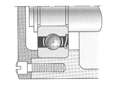
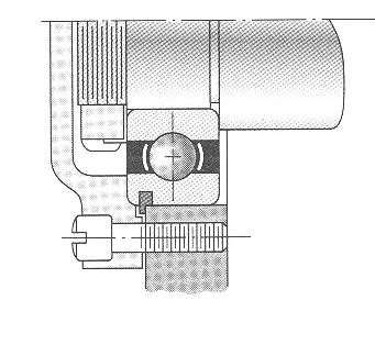
 ANGULAR CONTACT S ANGULAR CONTACT S Angular Contact Bearing Design Angular contact bearings have one ring shouler remove, this may be from the inner or outer ring. This allows a larger ball complement
Torsion of shafts with circular symmetry
 orsion of shafts with circular symmetry Introduction Consider a uniform bar which is subject to a torque, eg through the action of two forces F separated by distance d, hence Fd orsion is the resultant
[5] Stress and Strain
![[5] Stress and Strain](/thumbs/95/123344550.jpg "[5] Stress and Strain") [5] Stress and Strain Page 1 of 34 [5] Stress and Strain [5.1] Internal Stress of Solids [5.2] Design of Simple Connections (will not be covered in class) [5.3] Deformation and Strain [5.4] Hooke s Law
[5] Stress and Strain Page 1 of 34 [5] Stress and Strain [5.1] Internal Stress of Solids [5.2] Design of Simple Connections (will not be covered in class) [5.3] Deformation and Strain [5.4] Hooke s Law
Determine the resultant internal loadings acting on the cross section at C of the beam shown in Fig. 1 4a.
 E X M P L E 1.1 Determine the resultant internal loadings acting on the cross section at of the beam shown in Fig. 1 a. 70 N/m m 6 m Fig. 1 Support Reactions. This problem can be solved in the most direct
Shafts. Fig.(4.1) Dr. Salah Gasim Ahmed YIC 1
 Dr. Salah Gasim Ahmed YIC 1") Shafts. Power transmission shafting Continuous mechanical power is usually transmitted along and etween rotating shafts. The transfer etween shafts is accomplished y gears, elts, chains or other similar
Shafts. Power transmission shafting Continuous mechanical power is usually transmitted along and etween rotating shafts. The transfer etween shafts is accomplished y gears, elts, chains or other similar
University of Pretoria Department of Mechanical & Aeronautical Engineering MOW 227, 2 nd Semester 2014
 Universit of Pretoria Department of Mechanical & Aeronautical Engineering MOW 7, nd Semester 04 Semester Test Date: August, 04 Total: 00 Internal eaminer: Duration: hours Mr. Riaan Meeser Instructions:
General Data. Types of bearings 6. Standardization and interchangeability 12. Dimensions and part numbers 14. Bearing manufacturing precision 18
 General ata Types of bearings 6 efinitions 6 Vocabulary 8 Capabilities 9 Stanarization an interchangeability 12 The Stanars 12 Interchangeability 12 imensions an part numbers 14 General esignations 14
Drive Shaft Failure of Z-Drive Propulsion System. Suzanne Higgins
 Drive Shaft Failure of Z-Drive Propulsion System Suzanne Higgins Background Bunkering vessel MV Southern Valour Commissioned in 2008 in Singapore Operating in Cape Town harbour since August 2008 Z-Drive
Chapter 8 Structural Design and Analysis. Strength and stiffness 5 types of load: Tension Compression Shear Bending Torsion
 Chapter 8 Structural Design and Analysis 1 Strength and stiffness 5 types of load: Tension Compression Shear Bending Torsion Normal Stress Stress is a state when a material is loaded. For normal forces
SECOND ENGINEER REG. III/2 APPLIED MECHANICS
 SECOND ENGINEER REG. III/2 APPLIED MECHANICS LIST OF TOPICS Static s Friction Kinematics Dynamics Machines Strength of Materials Hydrostatics Hydrodynamics A STATICS 1 Solves problems involving forces
MECHANICS OF MATERIALS
 GE SI CHAPTER 3 MECHANICS OF MATERIALS Ferdinand P. Beer E. Russell Johnston, Jr. John T. DeWolf David F. Mazurek Torsion Lecture Notes: J. Walt Oler Texas Tech University Torsional Loads on Circular Shafts
MECHANICS OF MATERIALS Design of a Transmission Shaft
 Design of a Transmission Shaft If power is transferred to and from the shaft by gears or sprocket wheels, the shaft is subjected to transverse loading as well as shear loading. Normal stresses due to transverse
MECE 3321 MECHANICS OF SOLIDS CHAPTER 1
 MECE 3321 MECHANICS O SOLIDS CHAPTER 1 Samantha Ramirez, MSE WHAT IS MECHANICS O MATERIALS? Rigid Bodies Statics Dynamics Mechanics Deformable Bodies Solids/Mech. Of Materials luids 1 WHAT IS MECHANICS
6. Friction and viscosity in gasses
 IR2 6. Friction an viscosity in gasses 6.1 Introuction Similar to fluis, also for laminar flowing gases Newtons s friction law hols true (see experiment IR1). Using Newton s law the viscosity of air uner
MECH 401 Mechanical Design Applications
 MECH 401 Mechanical Design Applications Dr. M. O Malley Master Notes Spring 008 Dr. D. M. McStravick Rice University Updates HW 1 due Thursday (1-17-08) Last time Introduction Units Reliability engineering
7.6 Journal Bearings
 7.6 Journal Bearings 7.6 Journal Bearings Procedures and Strategies, page 1 of 2 Procedures and Strategies for Solving Problems Involving Frictional Forces on Journal Bearings For problems involving a
Aluminum shell. Brass core. 40 in
 PROBLEM #1 (22 points) A solid brass core is connected to a hollow rod made of aluminum. Both are attached at each end to a rigid plate as shown in Fig. 1. The moduli of aluminum and brass are EA=11,000
Mechanical Engineering Ph.D. Preliminary Qualifying Examination Solid Mechanics February 25, 2002
 student personal identification (ID) number on each sheet. Do not write your name on any sheet. #1. A homogeneous, isotropic, linear elastic bar has rectangular cross sectional area A, modulus of elasticity
ME Final Exam. PROBLEM NO. 4 Part A (2 points max.) M (x) y. z (neutral axis) beam cross-sec+on. 20 kip ft. 0.2 ft. 10 ft. 0.1 ft.
 M (x) y. z (neutral axis) beam cross-sec+on. 20 kip ft. 0.2 ft. 10 ft. 0.1 ft.") ME 323 - Final Exam Name December 15, 2015 Instructor (circle) PROEM NO. 4 Part A (2 points max.) Krousgrill 11:30AM-12:20PM Ghosh 2:30-3:20PM Gonzalez 12:30-1:20PM Zhao 4:30-5:20PM M (x) y 20 kip ft 0.2
ME 323 - Final Exam Name December 15, 2015 Instructor (circle) PROEM NO. 4 Part A (2 points max.) Krousgrill 11:30AM-12:20PM Ghosh 2:30-3:20PM Gonzalez 12:30-1:20PM Zhao 4:30-5:20PM M (x) y 20 kip ft 0.2
UNIT 3 Friction and Belt Drives 06ME54. Structure
 UNIT 3 Friction and Belt Drives 06ME54 Structure Definitions Types of Friction Laws of friction Friction in Pivot and Collar Bearings Belt Drives Flat Belt Drives Ratio of Belt Tensions Centrifugal Tension
MAE 322 Machine Design. Dr. Hodge Jenkins Mercer University
 MAE 322 Machine Design Dr. Hodge Jenkins Mercer University What is this Machine Design course really about? What you will learn: How to design machine elements 1) Design so they won t break under varying
D : SOLID MECHANICS. Q. 1 Q. 9 carry one mark each.
 GTE 2016 Q. 1 Q. 9 carry one mark each. D : SOLID MECHNICS Q.1 single degree of freedom vibrating system has mass of 5 kg, stiffness of 500 N/m and damping coefficient of 100 N-s/m. To make the system
[7] Torsion. [7.1] Torsion. [7.2] Statically Indeterminate Torsion. [7] Torsion Page 1 of 21
![[7] Torsion. [7.1] Torsion. [7.2] Statically Indeterminate Torsion. [7] Torsion Page 1 of 21](/thumbs/88/115835122.jpg "[7] Torsion. [7.1] Torsion. [7.2] Statically Indeterminate Torsion. [7] Torsion Page 1 of 21") [7] Torsion Page 1 of 21 [7] Torsion [7.1] Torsion [7.2] Statically Indeterminate Torsion [7] Torsion Page 2 of 21 [7.1] Torsion SHEAR STRAIN DUE TO TORSION 1) A shaft with a circular cross section is
[7] Torsion Page 1 of 21 [7] Torsion [7.1] Torsion [7.2] Statically Indeterminate Torsion [7] Torsion Page 2 of 21 [7.1] Torsion SHEAR STRAIN DUE TO TORSION 1) A shaft with a circular cross section is
3.5 STRESS AND STRAIN IN PURE SHEAR. The next element is in a state of pure shear.
 3.5 STRESS AND STRAIN IN PURE SHEAR The next element is in a state of pure shear. Fig. 3-20 Stresses acting on a stress element cut from a bar in torsion (pure shear) Stresses on inclined planes Fig. 3-21
Design of Combined Footings
 7 Design of Combine Footings Summary of combine footing esign is shown in the following steps. 1- Select a trial footing epth. - Establish the require base area of the footing: Uniform soil pressure is
2. Rigid bar ABC supports a weight of W = 50 kn. Bar ABC is pinned at A and supported at B by rod (1). What is the axial force in rod (1)?
. What is the axial force in rod (1)?") IDE 110 S08 Test 1 Name: 1. Determine the internal axial forces in segments (1), (2) and (3). (a) N 1 = kn (b) N 2 = kn (c) N 3 = kn 2. Rigid bar ABC supports a weight of W = 50 kn. Bar ABC is pinned at
IDE 110 S08 Test 1 Name: 1. Determine the internal axial forces in segments (1), (2) and (3). (a) N 1 = kn (b) N 2 = kn (c) N 3 = kn 2. Rigid bar ABC supports a weight of W = 50 kn. Bar ABC is pinned at
Stress Transformation Equations: u = +135 (Fig. a) s x = 80 MPa s y = 0 t xy = 45 MPa. we obtain, cos u + t xy sin 2u. s x = s x + s y.
 s x = 80 MPa s y = 0 t xy = 45 MPa. we obtain, cos u + t xy sin 2u. s x = s x + s y.") 014 Pearson Education, Inc., Upper Saddle River, NJ. All rights reserved. This material is protected under all copyright laws as they currently 9 7. Determine the normal stress and shear stress acting
014 Pearson Education, Inc., Upper Saddle River, NJ. All rights reserved. This material is protected under all copyright laws as they currently 9 7. Determine the normal stress and shear stress acting
GATE SOLVED PAPER - ME
 YEAR 01 ONE MARK Q. 1 A metric threas of itch mm an threa angle 60c is insecte for its itch iameter using -wire metho. The iameter of the best size wire in mm is (A) 0.866 (B) 1.000 (C) 1.15 (D).000 Q.
STATICS. Friction VECTOR MECHANICS FOR ENGINEERS: Eighth Edition CHAPTER. Ferdinand P. Beer E. Russell Johnston, Jr.
 Eighth E 8 Friction CHAPTER VECTOR MECHANICS FOR ENGINEERS: STATICS Ferdinand P. Beer E. Russell Johnston, Jr. Lecture Notes: J. Walt Oler Texas Tech University Contents Introduction Laws of Dry Friction.
MECHANICAL ENGINEERING» COURSE:
 PROGRAMME: «BSc in MECHANICAL ENGINEERING» COURSE: Machine Elements I - AMEM 316 ACADEMIC YEAR: 20013-14 INSTRUCTOR: Dr. Antonios Lontos DATE: 06/12/2013 Assignment 1: «SHAFT DESIGN» Prepared by: Aaaa
(48) CHAPTER 3: TORSION
 CHAPTER 3: TORSION") (48) CHAPTER 3: TORSION Introduction: In this chapter structural members and machine parts that are in torsion will be considered. More specifically, you will analyze the stresses and strains in members
(48) CHAPTER 3: TORSION Introduction: In this chapter structural members and machine parts that are in torsion will be considered. More specifically, you will analyze the stresses and strains in members
Improvement in the Design & Manufacturing of Twin Worm Self Locking Technique and applications
 Improvement in the Design & Manufacturing of Twin Worm Self Locking Technique and applications Prof. P.B. Kadam 1, Prof. M.R. Todkar 2 1 Assistant Professor, Mechanical Engineering Department, T.K.I.E.T.Warananagar,
CLUTCHES AND BRAKES. Square-jaw clutch
 Clutches: CLUTCHES AND BRAKES A Clutch is a mechanical device which is used to connect or disconnect the source of power from the remaining parts so the power transmission system at the will of the operator.
MAE 322 Machine Design Lecture 2. Dr. Hodge Jenkins Mercer University
 MAE 322 Machine Design Lecture 2 Dr. Hodge Jenkins Mercer University Statics Load Failure Theories to Understand Maximum Normal Stress (MNS) Maximum Shear Stress (MSS) Distortion Energy (DE) Coulomb-Mohr
EMA 3702 Mechanics & Materials Science (Mechanics of Materials) Chapter 3 Torsion
 Chapter 3 Torsion") EMA 3702 Mechanics & Materials Science (Mechanics of Materials) Chapter 3 Torsion Introduction Stress and strain in components subjected to torque T Circular Cross-section shape Material Shaft design Non-circular
EMA 3702 Mechanics & Materials Science (Mechanics of Materials) Chapter 3 Torsion Introduction Stress and strain in components subjected to torque T Circular Cross-section shape Material Shaft design Non-circular
WORCESTER POLYTECHNIC INSTITUTE
 WORCESTER POLYTECHNIC INSTITUTE MECHANICAL ENGINEERING DEPARTMENT STRESS ANALYSIS ES-2502, C 2012 Lecture 03: Stress 17 January 2012 General information Instructor: Cosme Furlong HL-151 (508) 831-5126
R13. II B. Tech I Semester Regular Examinations, Jan MECHANICS OF SOLIDS (Com. to ME, AME, AE, MTE) PART-A
 PART-A") SET - 1 II B. Tech I Semester Regular Examinations, Jan - 2015 MECHANICS OF SOLIDS (Com. to ME, AME, AE, MTE) Time: 3 hours Max. Marks: 70 Note: 1. Question Paper consists of two parts (Part-A and Part-B)
SET - 1 II B. Tech I Semester Regular Examinations, Jan - 2015 MECHANICS OF SOLIDS (Com. to ME, AME, AE, MTE) Time: 3 hours Max. Marks: 70 Note: 1. Question Paper consists of two parts (Part-A and Part-B)
Module 2 Stresses in machine elements. Version 2 ME, IIT Kharagpur
 Module Stresses in machine elements Lesson Compound stresses in machine parts Instructional Objectives t the end of this lesson, the student should be able to understand Elements of force system at a beam
Crossed Roller Bearings
 Special Selection & http://www.ikont.eu Official Distributer in Unite Kingom rosse Bearings Unit rackley Way Peartree Lane Duley, West Milans DY UW Tel : 9 / E-mail : uley@goiva-bearings.co.uk for AT-EG
Torsional and Bending Stresses in Machine Parts
 10 n A Textbook of Machine Design C 5 H A P T E R Torsional and Bending Stresses in Machine Parts 1. Introduction.. Torsional Shear Stress.. Shafts in Series and Parallel.. Bending Stress in Straight Beams.
Mechanical Principles
 Unit 8: Unit code Mechanical Principles F/615/1482 Unit level 4 Credit value 15 Introduction Mechanical principles have been crucial for engineers to convert the energy produced by burning oil and gas
Matlab Sheet 2. Arrays
 Matlab Sheet 2 Arrays 1. a. Create the vector x having 50 logarithmically spaced values starting at 10 and ending at 1000. b. Create the vector x having 20 logarithmically spaced values starting at 10
CE2253- APPLIED HYDRAULIC ENGINEERING (FOR IV SEMESTER)
") CE5-APPLIED HYDRAULIC ENGINEERING/UNIT-II/UNIFORM FLOW CE5- APPLIED HYDRAULIC ENGINEERING (FOR IV SEMESTER) UNIT II- UNIFORM FLOW CE5-APPLIED HYDRAULIC ENGINEERING/UNIT-II/UNIFORM FLOW CE5- APPLIED HYDRAULIC
CE5-APPLIED HYDRAULIC ENGINEERING/UNIT-II/UNIFORM FLOW CE5- APPLIED HYDRAULIC ENGINEERING (FOR IV SEMESTER) UNIT II- UNIFORM FLOW CE5-APPLIED HYDRAULIC ENGINEERING/UNIT-II/UNIFORM FLOW CE5- APPLIED HYDRAULIC
STRESS STRAIN AND DEFORMATION OF SOLIDS, STATES OF STRESS
 1 UNIT I STRESS STRAIN AND DEFORMATION OF SOLIDS, STATES OF STRESS 1. Define: Stress When an external force acts on a body, it undergoes deformation. At the same time the body resists deformation. The
Mechanical Principles
 Unit 4: Mechanical Principles Unit code: F/601/1450 QCF level: 5 Credit value: 15 Aim This unit aims to develop learners understanding of an extended range of mechanical principles that underpin the design
FME461 Engineering Design II
 FME461 Engineering Design II Dr.Hussein Jama Hussein.jama@uobi.ac.ke Office 414 Lecture: Mon 8am -10am Tutorial Tue 3pm - 5pm 10/1/2013 1 Semester outline Date Week Topics Reference Reading 9 th Sept 1
PROBLEM #1.1 (4 + 4 points, no partial credit)
") PROBLEM #1.1 ( + points, no partial credit A thermal switch consists of a copper bar which under elevation of temperature closes a gap and closes an electrical circuit. The copper bar possesses a length
PROBLEM #1.1 ( + points, no partial credit A thermal switch consists of a copper bar which under elevation of temperature closes a gap and closes an electrical circuit. The copper bar possesses a length
Rotating Bending with Constant Torsion and Rotated Bending with Constant or Variable Torsion
 Rotating Bending with Constant Torsion and Rotated Bending with Constant or Variable Torsion B. I. Stoychev 1, S. H. Stefanov 2 1 Department of Engineering Mechanics, Technical University of Gabrovo, 4
UNIT 1 STRESS STRAIN AND DEFORMATION OF SOLIDS, STATES OF STRESS 1. Define stress. When an external force acts on a body, it undergoes deformation.
 UNIT 1 STRESS STRAIN AND DEFORMATION OF SOLIDS, STATES OF STRESS 1. Define stress. When an external force acts on a body, it undergoes deformation. At the same time the body resists deformation. The magnitude
MAAE 2202 A. Come to the PASS workshop with your mock exam complete. During the workshop you can work with other students to review your work.
 It is most beneficial to you to write this mock final exam UNDER EXAM CONDITIONS. This means: Complete the exam in 3 hours. Work on your own. Keep your textbook closed. Attempt every question. After the
WINTER -14 EXAMINATION Subject Code: Model Answer Page No: 1/27
 Subject Code: 755 Model Answer Page No: /7 Important Instructions to examiners: ) The answers should be examined by key words and not as word-to-word as given in the model answer scheme. ) The model answer
Engineering Mechanics: Statics
 Engineering Mechanics: Statics Chapter 6B: Applications of Friction in Machines Wedges Used to produce small position adjustments of a body or to apply large forces When sliding is impending, the resultant
Verification of cylindrical interference fits under impact loads with LS-Dyna
 Verification of cylinrical interference fits uner impact loas with LS-Dyna Prof. Dr.-Ing. elmut Behler, Jan Göbel, M.Eng. ochschule Mannheim, Paul-Wittsack-Straße 10, D-68163 Mannheim, Germany Steffen
1 of 12. Given: Law of Cosines: C. Law of Sines: Stress = E = G
 ES230 STRENGTH OF MATERIALS FINAL EXAM: WEDNESDAY, MAY 15 TH, 4PM TO 7PM, AEC200 Closed book. Calculator and writing supplies allowed. Protractor and compass required. 180 Minute Time Limit You must have
MECE 3321: MECHANICS OF SOLIDS CHAPTER 5
 MECE 3321: MECHANICS OF SOLIDS CHAPTER 5 SAMANTHA RAMIREZ TORSION Torque A moment that tends to twist a member about its longitudinal axis 1 TORSIONAL DEFORMATION OF A CIRCULAR SHAFT Assumption If the
m (ft-lb/ft). Using the point-slope
. Using the point-slope") ENGR 1990 Engineering athematics pplications of Derivatives E 560, E 570 Eample #1 Consier a long slener beam of length with a concentrate loa acting at istance a from the left en. Due to this loa, the
ENGR 1990 Engineering athematics pplications of Derivatives E 560, E 570 Eample #1 Consier a long slener beam of length with a concentrate loa acting at istance a from the left en. Due to this loa, the
Combined Stresses and Mohr s Circle. General Case of Combined Stresses. General Case of Combined Stresses con t. Two-dimensional stress condition
 Combined Stresses and Mohr s Circle Material in this lecture was taken from chapter 4 of General Case of Combined Stresses Two-dimensional stress condition General Case of Combined Stresses con t The normal
QUESTION BANK SEMESTER: III SUBJECT NAME: MECHANICS OF SOLIDS
 QUESTION BANK SEMESTER: III SUBJECT NAME: MECHANICS OF SOLIDS UNIT 1- STRESS AND STRAIN PART A (2 Marks) 1. Define longitudinal strain and lateral strain. 2. State Hooke s law. 3. Define modular ratio,
MECHANICS OF SOLIDS Credit Hours: 6
 MECHANICS OF SOLIDS Credit Hours: 6 Teaching Scheme Theory Tutorials Practical Total Credit Hours/week 4 0 6 6 Marks 00 0 50 50 6 A. Objective of the Course: Objectives of introducing this subject at second
ME325 EXAM I (Sample)
") ME35 EXAM I (Sample) NAME: NOTE: COSED BOOK, COSED NOTES. ONY A SINGE 8.5x" ORMUA SHEET IS AOWED. ADDITIONA INORMATION IS AVAIABE ON THE AST PAGE O THIS EXAM. DO YOUR WORK ON THE EXAM ONY (NO SCRATCH PAPER
ME35 EXAM I (Sample) NAME: NOTE: COSED BOOK, COSED NOTES. ONY A SINGE 8.5x" ORMUA SHEET IS AOWED. ADDITIONA INORMATION IS AVAIABE ON THE AST PAGE O THIS EXAM. DO YOUR WORK ON THE EXAM ONY (NO SCRATCH PAPER
MECHANICS OF MATERIALS. Prepared by Engr. John Paul Timola
 MECHANICS OF MATERIALS Prepared by Engr. John Paul Timola Mechanics of materials branch of mechanics that studies the internal effects of stress and strain in a solid body. stress is associated with the
CE6306 STRENGTH OF MATERIALS TWO MARK QUESTIONS WITH ANSWERS ACADEMIC YEAR
 CE6306 STRENGTH OF MATERIALS TWO MARK QUESTIONS WITH ANSWERS ACADEMIC YEAR 2014-2015 UNIT - 1 STRESS, STRAIN AND DEFORMATION OF SOLIDS PART- A 1. Define tensile stress and tensile strain. The stress induced
Engineering Mechanics: Statics
 Engineering Mechanics: Statics Chapter 6B: Applications of Friction in Machines Wedges Used to produce small position adjustments of a body or to apply large forces When sliding is impending, the resultant
PES Institute of Technology
 PES Institute of Technology Bangalore south campus, Bangalore-5460100 Department of Mechanical Engineering Faculty name : Madhu M Date: 29/06/2012 SEM : 3 rd A SEC Subject : MECHANICS OF MATERIALS Subject
MECHANICS OF MATERIALS
 STATICS AND MECHANICS OF MATERIALS Ferdinand P. Beer E. Russell Johnston, Jr, John T. DeWolf David E Mazurek \Cawect Mc / iur/» Craw SugomcT Hilt Introduction 1 1.1 What is Mechanics? 2 1.2 Fundamental
Springs Lecture 3. Extension Springs
 Springs Lecture 3 Extension Springs Carry tensile loading Extension springs Max. Normal stress at A due to Bending and Axial loading σ A K A 6D 4 F K A + 3 πd πd 4C 4C C ( C ) r d C Max. torsional stress
b) 2/3 MR 2 c) 3/4MR 2 d) 2/5MR 2
 2/3 MR 2 c) 3/4MR 2 d) 2/5MR 2") Rotational Motion 1) The diameter of a flywheel increases by 1%. What will be percentage increase in moment of inertia about axis of symmetry a) 2% b) 4% c) 1% d) 0.5% 2) Two rings of the same radius and
Rotational Motion 1) The diameter of a flywheel increases by 1%. What will be percentage increase in moment of inertia about axis of symmetry a) 2% b) 4% c) 1% d) 0.5% 2) Two rings of the same radius and
Public Service Commission, West Bengal
 Public Service Commission, West Bengal Syllabus for the Written Test for recruitment to the posts of ASSISTANT ENGINEER (Agri - Mechanical) in West Bengal Service of Agricultural Engineers Mechanical Engineering
CE 221: MECHANICS OF SOLIDS I CHAPTER 1: STRESS. Dr. Krisada Chaiyasarn Department of Civil Engineering, Faculty of Engineering Thammasat university
 CE 221: MECHANICS OF SOLIDS I CHAPTER 1: STRESS By Dr. Krisada Chaiyasarn Department of Civil Engineering, Faculty of Engineering Thammasat university Agenda Introduction to your lecturer Introduction
Pressure Vessels Stresses Under Combined Loads Yield Criteria for Ductile Materials and Fracture Criteria for Brittle Materials
 Pressure Vessels Stresses Under Combined Loads Yield Criteria for Ductile Materials and Fracture Criteria for Brittle Materials Pressure Vessels: In the previous lectures we have discussed elements subjected
CIVL222 STRENGTH OF MATERIALS. Chapter 6. Torsion
 CIVL222 STRENGTH OF MATERIALS Chapter 6 Torsion Definition Torque is a moment that tends to twist a member about its longitudinal axis. Slender members subjected to a twisting load are said to be in torsion.
Classical Series Timing Belts
 Classical Series Timing s Classical Series Timing s are manufacture in 5 pitch sizes, X (/5), ( 3 / ), H ( / ), XH ( / ) an XXH ( / 4 ). Stanar stock lengths an withs are shown below, the XH an XXH Series
: APPLIED MECHANICS & STRENGTH OF MATERIALS COURSE CODE : 4021 COURSE CATEGORY : A PERIODS/ WEEK : 5 PERIODS/ SEMESTER : 75 CREDIT : 5 TIME SCHEDULE
 COURSE TITLE : APPLIED MECHANICS & STRENGTH OF MATERIALS COURSE CODE : 4021 COURSE CATEGORY : A PERIODS/ WEEK : 5 PERIODS/ SEMESTER : 75 CREDIT : 5 TIME SCHEDULE MODULE TOPIC PERIODS 1 Simple stresses
NAME: Given Formulae: Law of Cosines: Law of Sines:
 NME: Given Formulae: Law of Cosines: EXM 3 PST PROBLEMS (LESSONS 21 TO 28) 100 points Thursday, November 16, 2017, 7pm to 9:30, Room 200 You are allowed to use a calculator and drawing equipment, only.
1 of 7. Law of Sines: Stress = E = G. Deformation due to Temperature: Δ
 NME: ES30 STRENGTH OF MTERILS FINL EXM: FRIDY, MY 1 TH 4PM TO 7PM Closed book. Calculator and writing supplies allowed. Protractor and compass allowed. 180 Minute Time Limit GIVEN FORMULE: Law of Cosines: